

INDESIT I6T52(X)/AUS User Manual

Operating Instructions
COOKER AND OVEN
AU
English, 1
I6T52/AUS
Contents
Installation, 3-9
Positioning and levelling
Gas connection
Electrical connection
Adapting to different types of gas
Table of characteristics
Technical specifications
Description of the appliance, 11
Overall view
Control panel
Start-up and use, 10
Using the hob
Using the cooking timer
Cooking modes
Cooking advice table for the oven
Precautions and tips, 15
General Appliance Warning
Installation Warnings
Safety With the Cooktop
Maintenance Warnings
Gas And Electrical Safety
Respecting And Conserving
The Environment
AU
Care and maintenance, 17
Switching the appliance off
Cleaning the appliance
Inspecting The Oven Seals
Gas Tap Maintenance
Replacing the oven light bulb
Cleaning The Cooktop
Assistance

WARNING
AU
WARNING: The appliance and its accessible parts become hot during use.
Care should be taken to avoid touching
heating elements.
Children less than 8 years of age shall
be kept away unless continuously supervised.
This appliance can be used by children
aged from 8 years and above and persons with reduced physical, sensory or
mental capabilities or lack of experience and knowledge if they have been
given supervision or instruction concerning use of the appliance in a safe way
and understand the hazards involved.
Children shall not play with the appliance. Cleaning and user maintenance
shall not be made by children without
supervision.
The internal surfaces of the compartment (where present) may become hot.
Never use steam cleaners or pressure cleaners on the appliance.
Remove any liquid from
the lid before opening it.
Do not close the glass cover (if present) when the gas burners or electric hotplates are still hot.
WARNING: Ensure that the appliance is switched off before replacing
the lamp to avoid the possibility of
electric shock.
WARNING: Unattended cooking on a
hob with fat or oil can be dangerous
and may result in fire.
NEVER try to extinguish a fire with water, but switch off the appliance and
then cover flame e.g. with a lid or a fire
blanket.
Do not use harsh abrasive cleaners or
sharp metal scrapers to clean the oven
door glass since they can scratch the
surface, which may result in shattering
of the glass.
2
Installation
! Before operating your new appliance please read
this instruction booklet carefully. It contains important
information concerning the safe installation and
operation of the appliance.
! Please keep these operating instructions for future
reference. Make sure that the instructions are kept with
the appliance if it is sold, given away or moved.
! The appliance must be installed by a qualified
professional according to the instructions provided.
! Any necessary adjustment or maintenance must be
performed after the cooker has been disconnected
from the electricity supply.
Compliance with standards
This cooktop must be installed in accordance with the
requirements of local gas and electrical authorities, as
well as the latest published versions of the following
standards:
• AS/NZS 5601 Gas Installation code
• SAA Wiring Rules.
Positioning
! It is possible to install the appliance alongside
cupboards whose height does not exceed that of the
hob surface.
! This cooker should be installed directly on the floor.
Do not install this cooker on an artificial base of any
kind.
! Make sure that the wall in contact with the back of
the appliance is made from a non-flammable, heatresistant material (T 90°C).
! Important: Do not install this appliance adjacent to
the door or other means of access to minimise the
likelihood of persons using the door making contact
with pans on the hob surface.
Room Ventilation
Where the total input of all appliances exceeds 3
MJ/h for each cubic metre of the room or enclosure
volume, the space shall be ventilated by one of the
methods detailed below. For the purpose of assessing
the adequacy of ventilation, the space that cannot be
isolated by doors is the ‘volume of a room’.
Natural ventilation direct from outside
Two permanent openings shall be provided directly to
outside. The openings shall be located to ensure the
distance between the top of the upper opening and
the ceiling of the room or enclosure, and the distance
between the bottom of the lower opening and the floor
of the room or enclosure does not exceed 5% of the
height of the room or enclosure. The minimum free
ventilation area provided by each opening shall be
calculated using the following formula:
A = 3 × T
where
A = the minimum free ventilation area (cm
T = the total gas consumption of all appliances
(MJ/h)
The minimum vertical dimension of any free ventilation
opening shall be 6 mm.
NOTE 1 When used in this Clause, the term ‘directly
to outside’ means any one of the following options,
provided that the ventilation path is unobstructed by
building material or insulation:
(a) Directly through an outside wall (preferred
option).
(b) Through to an outside wall but offset.
(c) Into a cavity ventilated to outside.
(d) Into an underfloor space ventilated to outside.
(e) Into a roof space ventilated to outside.
NOTE 2 The two openings may be combined provided
that the top and bottom of the opening reach the limits
set by this Clause.
Natural ventilation via adjacent room
Two permanent openings shall be provided in the room
or enclosure. The openings shall be located to ensure
the distance between the top of the upper opening and
the ceiling of the room or enclosure, and the distance
between the bottom of the lower opening and the floor
of the room or enclosure does not exceed 5% of the
height of the room or enclosure.
The minimum free ventilation area provided by each
opening shall be calculated using the following
formula:
A = 6 × T
where
A = the minimum free ventilation area (cm
T = the total gas consumption of all appliances
(MJ/h)
These requirements shall apply to all subsequent
rooms until a room is ventilated to outside, in
accordance with the previous section, or the total input
of the appliances does not exceed 3 MJ/h for each
cubic metre of the total volume of the enclosure and
rooms.
The minimum vertical dimension of any free ventilation
opening shall be 6 mm.
2
)
2
)
AU
3

AU
NOTE: The two openings may be combined provided
that the top and bottom of the opening reach the limits
set by this Clause.
To install the appliance correctly:
• Place it in the kitchen, dining room or the bed-sit (not
in the bathroom).
• If the top of the hob is higher than the cupboards,
the appliance must be installed at least 200 mm away
from them.
• If the cooker is installed underneath a wall cabinet,
there must be a minimum distance of 420 mm
between this cabinet and the top of the hob.
This distance should be increased to 700 mm if the
wall cabinets are flammable (see figure).
The following minimum clearances to combustible
materials must be observed:
• Minimum clearance from edge of burner to side wall
must be 200 mm.
Minimum clearance from edge of burner to rear wall
must be 200 mm.
• Do not position blinds behind the cooker or less than
200 mm away from its sides.
Range hoods
Range hoods and overhead exhaust fans must be
installed according to manufacturers’ instructions
but in no case shall clearance from hob burners be
less than 600 mm for range hoods and 750 mm for
overhead exhaust fans.
If the hood is installed below a wall cabinet, the latter
must be at least 700 mm (millimetres) above the
surface of the hob.
Levelling
If it is necessary to level the appliance, screw the
adjustable feet into the places provided on each
corner of the base of the cooker (see figure).
The legs* fit into the slots on the underside of the base
of the cooker.
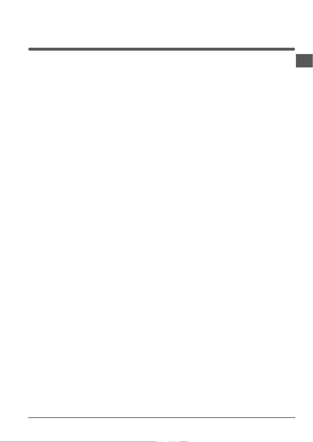
Installation of the cooker
The appliance can be installed next to furniture units
which are no taller than the top of the cooker hob.
The wall in direct contact with the back panel of the
cooker must be made of non-flammable material.
During operation the back panel of the cooker could
reach a temperature of 50°C above room temperature.
For proper installation of the cooker, the following
precautions must be taken:
a) The appliance can be placed in a kitchen, dining
room or bedsit, but not in a bathroom.
b) All furniture around the appliance must be placed at
least 200 mm from the top of the cooker, should the
surface of the appliance be higher than the worktop
of this furniture. Curtains should not be placed
behind the cooker or less than 200 mm away from
the sides of the appliance.
c) Any hoods must be installed according to the
requirements in the installation manual for the hoods
themselves.
d) If the cooker is installed beneath a wall cabinet, the
latter must be situated at a minimum of 420 mm
above the hob. The minimum distance between
the worktop and kitchen units made of combustible
material is 700 mm (Fig. A).
e) The wall in direct contact with the back panel of the
cooker must be made of non-flammable materials.
f) The cooker is fitted with a safety chain that must be
attached to a screw, secured to the wall behind the
appliance.
! Some models can have their gas connection
inverted. It is important to make sure the safety
chain is always situated on the side which
corresponds to the hose holder (Fig. B).
4
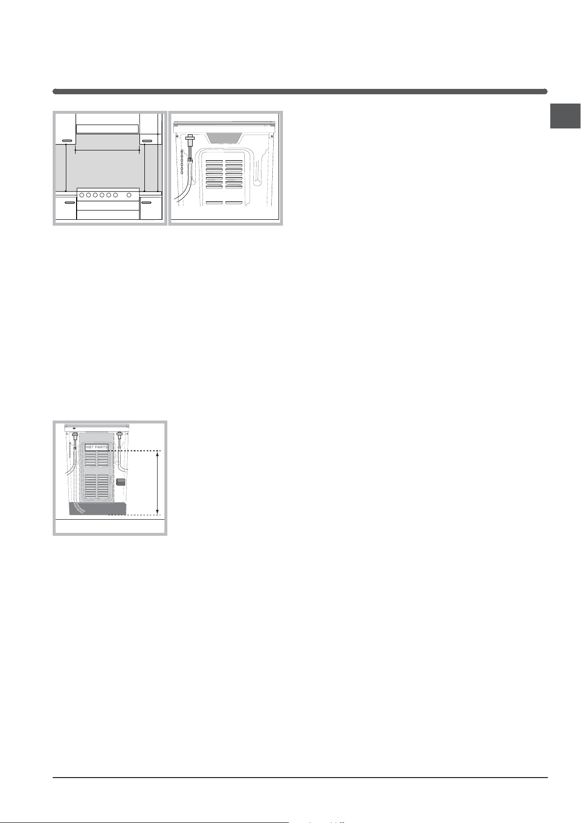
Fig. A Fig. B
700 mm
HOT PARTS
HOOD
420
Min.
min.
650
mm. with hood
min.
700
mm. without hood
mm.
600
Min. mm.
420
Min. mm.
Gas connection
This appliance is suitable for use with either a
fl exible connection or rigid copper connection.
Check The Gas Type
possible with a maximum length of 1.5 metres;
• The flexible connection must be approved to class B
or D of AS/NZS1869 as a minimum.
• it should not be bent, kinked or compressed;
• it should not be in contact with the rear wall of the
appliance or in any case with parts which may reach
a temperature of 50°C;
• it should not come into contact with pointed parts or
sharp corners;
• it should not be subject to any pulling or twisting
forces;
• it should be easy to inspect along its entire length in
order to be able to check its condition.
• The supply connection point must be accessible
with the appliance installed.
• The inner diameters of the pipe are as follows:
8 mm for LPG;
13 mm for Natural Gas.
AU
WARNING: Before installation, check that the gas
type (natural gas or LPG/Propane) of the cooker is
suitable for the gas type available to the installation. It
is extremely dangerous to use the wrong gas type with
any appliance, as fire or serious injury can result.
This cooker is supplied from the factory already set for
Natural Gas. To convert
the cooker to LPG (or
back to Natural Gas
from LPG), follow the
directions later in this
section.
Fit regulator supplied
for Natural Gas (if
applicable) at rear of
appliance, and as close
as practicable to the
appliance.
It is recommended that an isolating valve and union
be fitted, to enable simple disconnection for servicing.
These are to be in an accessible location.
.
! Make sure the supply pressure conforms with the
values shown in the table entitled “Caracteristics of the
burners and nozzles”.
When the cooker is installed between cabinets
(recessed), the gas connection must be effected by
an approved flexible hose with bayonet fitting (BS
669 Current Edition). The gas inlet for the cookers is a
threaded G 1/2 gas female fitting.
Connecting the gas supply
If a flexible hose is used, it should be as short as
Upon completion of installation, check the gas circuit,
the internal connections and the taps for leaks using
a soapy solution (never a flame). Also check that the
connecting pipe cannot come into contact with moving
parts which could damage or crush it. Make sure that
the natural gas pipe is adequate for a sufficient supply
to the appliance when all the burners are lit.
Duplicate Data Plate
Where the data plate is obscured by cabinetry when
the cooker is in the installed position, place a duplicate
data plate on a surface of the cabinetry adjacent to the
cooker.
Electrial connection
Power supply voltage and frequency: 220-240V a.c.
50/60 Hz.
! The supply cable must be positioned so that it never
reaches at any point a temperature 50°C higher than
the room temperature. The cable must be routed away
from the rear vents. Should you require it, you may
use a longer cable, however, you must ensure that the
cable supplied with the appliance is replaced by one
of the same specifications in accordance with current
standards and legislation.
Your appliance is supplied with a 13 amp fused
plug that can be plugged into a 13 amp socket for
immediate use. Before using the appliance please read
the instructions below.
WARNING - THIS APPLIANCE MUST BE EARTHED.
THE FOLLOWING OPERATIONS SHOULD BE
CARRIED OUT BY A QUALIFIED ELECTRICIAN.
5

GREEN &
YELLOW
BROWN
BLUE
13 amp fuse
CROSS-BAR
CORD GRIP
AU
Replacing the fuse:
When replacing a faulty fuse, a 13 amp ASTA
approved fuse to BS 1362 should always be used, and
the fuse cover re-fitted. If the fuse cover is lost, the
plug must not be used until a replacement is obtained.
Replacement fuse covers:
If a replacement fuse cover is fitted, it must be of the
correct colour as indicated by the coloured marking
or the colour that is embossed in words on the base of
the plug. Replacements can be obtained directly from
your nearest Service Depot.
Removing the plug:
If your appliance has a non-rewireable moulded plug
and you should wish to remove it to add a cable
extension or to re-route the mains cable through
partitions, units etc., please ensure that either:
• the plug is replaced by a fused 13 amp re-wireable
plug bearing the BSI mark of approval.
or:
• the mains cable is wired directly into a 13 amp cable
outlet, controlled by a switch, (in compliance with
BS 5733) which is accessible without moving the
appliance.
! For appliances with a rating greater than 13 amp (eg:
electric hob, double ovens and freestanding electric
cookers etc.) the mains cable must be wired into a
cooker output point with a rating of 45 amp. In this
case the cable is not supplied.
Disconnecting the cable
Ensure that the means for disconnection of the
power cable is incorporated into the fixed wiring in
accordance with local wiring rules.
(New Zealand statutory warning): The cooker must be
connected to the electricity supply by a cable fitted
with an appropriately rated plug that is compatible with
the socket-outlet fitted to the final subcircuit in the fixed
wiring that is intended to supply this cooker.
Disposing of the plug:
accordance with the following code:
Green & Yellow - Earth
Blue - Neutral
Brown - Live
If the colours of the wires in the mains lead do not
correspond with the coloured markings identifying the
terminals in your plug, proceed as follows:
Connect Green & Yellow wire to terminal marked “E” or or
coloured Green or Green & Yellow.
Connect Brown wire to terminal marked “L” or coloured
Red.
Connect Blue wire to terminal marked “N” or coloured
Black.
If a 13 amp plug (BS 1363) is used it must be fitted with a
13 amp fuse. A 15 amp plug must be protected by a 15
amp fuse, either in the plug or adaptor or at the distribution
board. If you are in any doubt about the electrical supply
to your machine, consult a qualified electrician before use.
How to connect an alternative plug:
The wires in this mains lead are coloured in accordance
with the following code:
BLUE
“NEUTRAL” (“N”)
BROWN
“LIVE” (“L”)
GREEN AND YELLOW
“EARTH” (“E”)
Disposing of the appliance
When disposing of the appliance please remove the plug
by cutting the mains cable as close as possible to the plug
body and dispose of it as described above.
Checking the connection for leaks
Upon completion of installation, check the gas circuit, the
internal connections and the taps for leaks using a soapy
solution (never a flame). Also check that the connecting
pipe cannot come into contact with moving parts which
could damage or crush it. Make sure that the natural gas
pipe is adequate for a sufficient supply to the appliance
when all the burners are lit.
Ensure that before disposing of the plug itself,
you make the pins unusable so that it cannot be
accidentally inserted into a socket. Instructions for
connecting cable to an alternative plug:
! The wires in the mains lead are coloured in
6
Adapting to different types of gas
It is possible to adapt the appliance to a type of gas other
than the default type (this is indicated on the rating label
on the cover).
 Loading...