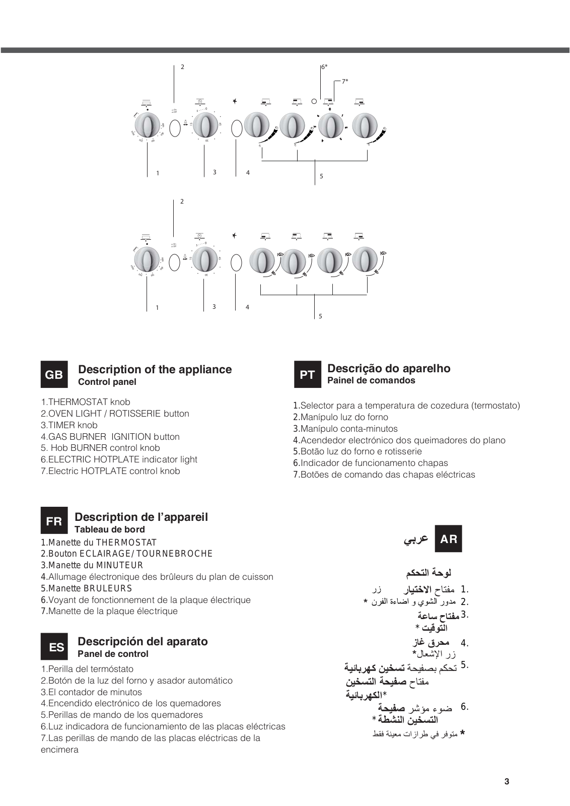
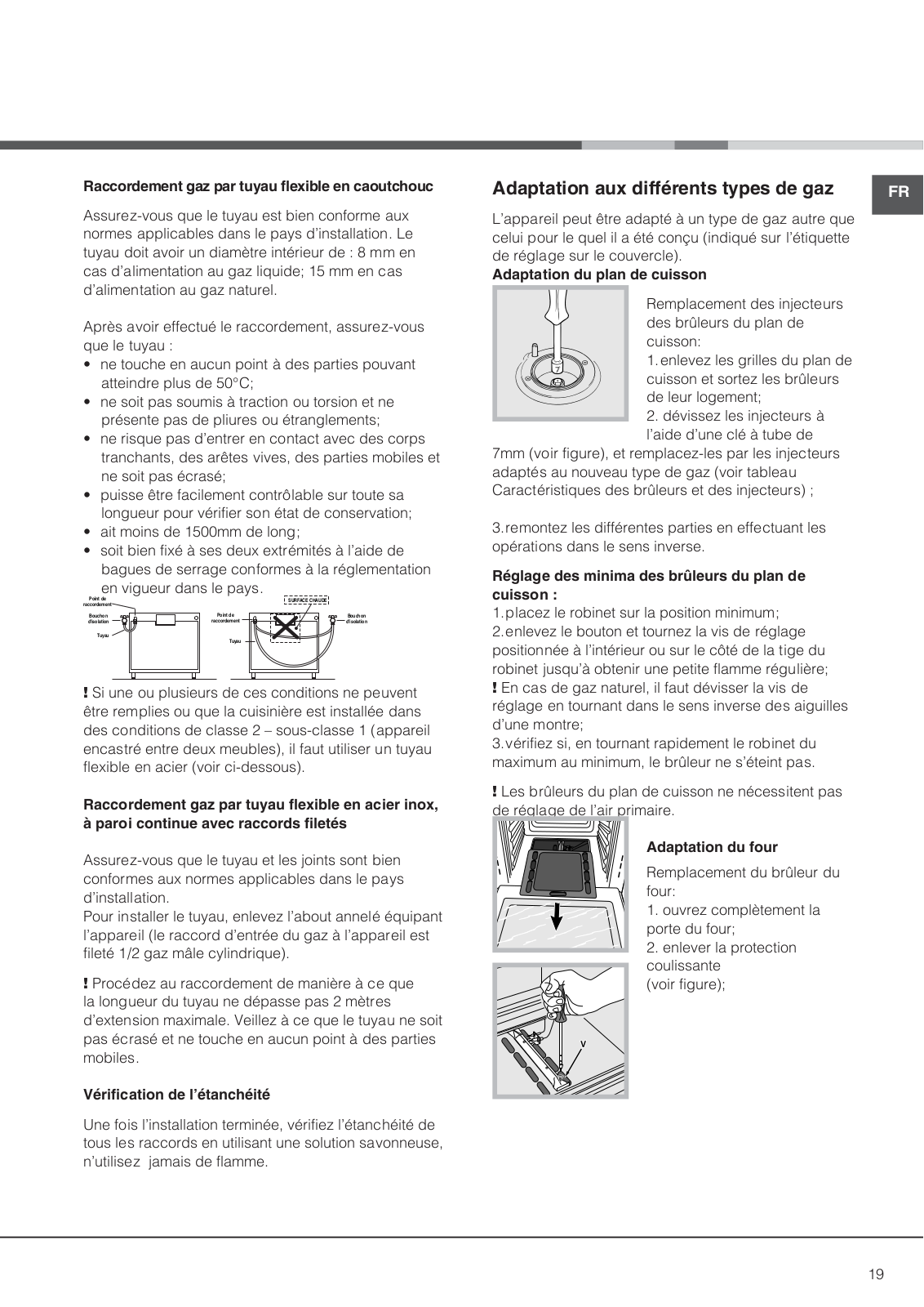
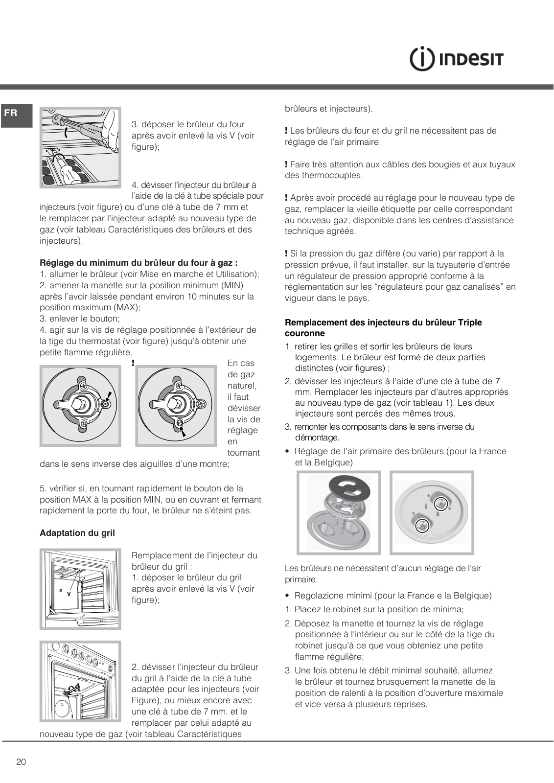
INDESIT I6MG1G(X)/EX User Manual

I6MG1G / EX

I6GG10G /EX

I6TG1G /EX

I6TG1G.K / EX

I6TG1G GH / EX


GB English

Operating Instructions

COOKER AND OVEN

Contents

Operating Instructions,1

Description of the appliance-Overall view,2 Description of the appliance-Control Panel,3 Installation,4

Start-up and use,10 Precautions and tips,13 Care and maintenance,14 Assistance,14

FR Français

Mode d’emploi

CUISINIERE ET FOUR

Sommaire

Mode d’emploi,1

Description de l’appareil-Vue d’ensemble, 2 Description de l’appareil-Tableau de bord, 3 Installation,16

Mise en marche et utilisation,22 Précautions et conseils, 25 Nettoyage et entretien,26 Assistance,27

ES Español

Manual de instrucciones

COCINA Y HORNO

Sumario

Manual de instrucciones,1

Descripción del aparato-Vista de conjunto,2 Descripción del aparato-Panel de control,3 Instalación,28

Puesta en funcionamiento y uso,34 Precauciones y consejos,37 Mantenimiento y cuidados,38 Asistencia,38

PT Português

Instruções para a utilização

FOGÃO E FORNO

Índice

Instruções para a utilização,1

Descrição do aparelho-Vista de conjunto,2 Descrição do aparelho-Painel de comandos,3 Instalaçao,40

Início e utilizaçao, 46 Precauçoes e conselhos,49 Manutençao e cuidados,50 Assistencia técnica,50


AR


ﻞﻴﻐﺸﺘﻟا تﺎﻤﻴﻠﻌﺗ


خﺎّﺒﻃ


تﺎﻳﻮﺘﺤﻤﻟا

1

ﻞﻴﻐﺸﺘﻟا تﺎﻤﻴﻠﻌﺗ

2

زﺎﻬﺠﻟا ﻒﺻو

ﺔﻣﺎﻋ ةﺮﻈﻧ

3

ﻢﻜﺤﺘﻟا ﺔﺣﻮﻟ


ﺐﻴﻛﺮﺘﻟا

ماﺪﺨﺘﺳﻻاو ﻞﻴﻐﺸﺘﻟا ﺢﺋﺎﺼﻧورﺬﺣ ﻞﺋﺎﺳو ﺔﻧﺎﻴﺼﻟاو ﺔﻳﺎﻨﻌﻟا

15

1

7

2

8

3

9

4

10

11

5

12


13

6

14

6

ES

Descripción del aparato


Vista de conjunto

1.Quemador de gas

2. Plano de contención eventuales derrames 3.Panel de mandos

4.Rejilla estante del horno 5.Asadera o plano de cocción 6.Patitas regulables

7.ENCIMERA ELÉCTRICA

8.Rejilla del plano de cocción

9. GUÍAS de deslizamiento de las bandejas

10.POSICIÓN 5

11.POSICIÓN 4

12. POSICIÓN 3

13.POSICIÓN 2

14.POSICIÓN 1

15.Tapa de vidrio (Presente sólo en algunos modelos)

GB

Description of the appliance

Overall view


1.Hob burner 2.Hob Grid 3.Control panel 4.Sliding grill rack 5.DRIPPING pan 6.Adjustable foot

7.ELECTRIC HOTPLATE 8.Containment surface for spills 9.GUIDE RAILS for the sliding racks 10.position 5

11.position 4 12.position 3 13.position 2 14.position 1

15.Glass Cover *(Available only on certain models)

PT

Descrição do aparelho


Vista de conjunto


1.Queimador a gás

2.Grade do piano de trabalho 3.Painel de comandos 4.Prateleira GRADE

5.Prateleira BANDEJA PINGADEIRA 6. Pé de regulação

7.Plano eléctrico

8.Plano de retenção dos eventuais vazamentos 9.GUIAS de deslizamento das prateleiras 10.Posição 5

11.Posição 4 12.Posição 3

13.Posição 2

14.Posição 1

15.O sobretampo de vidro

(Presente apenas em alguns modelos)


Description de l’appareil


زﺎﻬﺠﻟا ﻒﺻو


AR

FR

Vue d’ensemble


ﺔﻣﺎﻋ ةﺮﻈﻧ


1.Brûleur à gaz

2.Grille du plan de cuisson

3.Tableau de bord 4.Support GRILLE 5.Support LECHEFRITE 6.Pied de réglage

7.Table de cuisson electrique

8.Plateau du plan de cuisson

9.GLISSIERES de coulissement

10.niveau 5

11.niveau 4

12.niveau 3

13.niveau 2

14.niveau 1

15.Couvercle en verre (N’existe que sur certains modèles)

1.

2.

3.

4.

5.

6.

7.

8. 9.

10.

11.

12

13.

14. 15.

2


2

6*

7*

6

1


3

4


5


2


6

1


3

4


5

GB

Description of the appliance

Control panel


1.THERMOSTAT knob

2.OVEN LIGHT / ROTISSERIE button 3.TIMER knob

4.GAS BURNER IGNITION button 5. Hob BURNER control knob

6.ELECTRIC HOTPLATE indicator light 7.Electric HOTPLATE control knob

PT

Descrição do aparelho


Painel de comandos


1.Selector para a temperatura de cozedura (termostato)

2.Manípulo luz do forno

3.Manípulo conta-minutos

4.Acendedor electrónico dos queimadores do plano

5.Botão luz do forno e rotisserie

6.Indicador de funcionamento chapas

7.Botões de comando das chapas eléctricas

FR

Description de l’appareil


Tableau de bord

1.Manette du THERMOSTAT

2.Bouton ECLAIRAGE/ TOURNEBROCHE 3.Manette du MINUTEUR

4.Allumage électronique des brûleurs du plan de cuisson

5.Manette BRULEURS

6.Voyant de fonctionnement de la plaque électrique

7.Manette de la plaque électrique

ES

Descripción del aparato


Panel de control

1.Perilla del termóstato

2.Botón de la luz del forno y asador automático 3.El contador de minutos

4.Encendido electrónico de los quemadores 5.Perillas de mando de los quemadores

6.Luz indicadora de funcionamiento de las placas eléctricas 7.Las perillas de mando de las placas eléctricas de la encimera


AR


ﻢﻜﺤﺘﻟا ﺔﺣﻮﻟ


رز

ﺭﺎﻴﺘﺧﻻﺍ ﺡﺎﺘﻔﻣ

1.

* نﺮﻔﻟا ةءﺎﺿا و يﻮﺸﻟا روﺪﻣ

2.


ﺔﻋﺎﺳ حﺎﺘﻔﻣ3.


* ﺖﻴﻗﻮﺘﻟا


زﺎﻏ قﺮﺤﻣ

4.


*لﺎﻌﺷﻹا رز


ﺔﻴﺋﺎﺑﺮﻬﻛ ﻦﻴﺨﺴﺗ ﺔﺤﻴﻔﺼﺑ ﻢﻜﺤﺗ 5. ﻦﻴﺨﺴﺘﻟﺍ ﺔﺤﻴﻔﺻ ﺡﺎﺘﻔﻣ

ﺔﻴﺋﺎﺑﺮﻬﻜﻟﺍ*

ﺔﺤﻴﻔﺻ ﺮﺷﺆﻣ ءﻮﺿ 6. * ﺔﻄﺸﻨﻟﺍ ﻦﻴﺨﺴﺘﻟﺍ

ﻂﻘﻓ ﺔﻨﻴﻌﻣ تازاﺮﻃ ﻲﻓ ﺮﻓﻮﺘﻣ *

3

Installation

! Before operating your new appliance please read GB this instruction booklet carefully. It contains important

information concerning the safe installation and operation of the appliance.

!Please keep these operating instructions for future reference. Make sure that the instructions are kept with the appliance if it is sold, given away or moved.

!The appliance must be installed by a qualified professional according to the instructions provided.

!Any necessary adjustment or maintenance must be performed after the cooker has been disconnected from the electricity supply.

Room ventilation

The appliance may only be installed in permanentlyventilated rooms, according to current national legislation. The room in which the appliance is installed must be ventilated adequately so as to provide as much air as is needed by the normal gas combustion process (the flow of air must not be lower than 2 m3/h per kW of installed power).

The air inlets, protected by grilles, should have a duct with an inner cross section of at least 100 cm2 and should be positioned so that they are not liable to even partial obstruction (see figure A).

These inlets should be enlarged by 100% - with a minimum of 200 cm2 - whenever the surface of the hob is not equipped with a flame failure safety device. When the flow of air is provided in an indirect manner from adjacent rooms (see figure B), provided that these are not communal parts of a building, areas with increased fire hazards or bedrooms, the inlets should be fitted with a ventilation duct leading outside as described above.

Adjacent room

Room

requiring

ventilation

A


Ventilation opening

Increase in the gap

between the door and

for comburent air

A

Bthe flooring

! After prolonged use of the appliance, it is advisable to open a window or increase the speed of any fans used.

Disposing of combustion fumes

The disposal of combustion fumes should be guaranteed using a hood connected to a safe and efficient natural suction chimney, or using an electric fan that begins to operate automatically every time the appliance is switched on (see figure).


Fumes channelled

Fumes channelled through

straight outside

a chimney or a branched


flue system (reserved for


cooking appliances)

! The liquefied petroleum gases are heavier than air and collect by the floor, therefore all rooms containing LPG cylinders must have openings leading outside so that any leaked gas can escape easily.

LPG cylinders, therefore, whether partially or completely full, must not be installed or stored in rooms or storage areas that are below ground level (cellars, etc.). Only the cylinder being used should be stored

in the room; this should also be kept well away from sources of heat (ovens, chimneys, stoves) that may cause the temperature of the cylinder to rise above 50°C.

Positioning and levelling

!It is possible to install the appliance alongside cupboards whose height does not exceed that of the hob surface.

!Make sure that the wall in contact with the back of the appliance is made from a non-flammable, heatresistant material (T 90°C).

To install the appliance correctly:

Place it in the kitchen, dining room or the bed-sit (not in the bathroom).

If the top of the hob is higher than the cupboards, the appliance must be installed at least 600 mm away from them.

If the cooker is installed underneath a wall cabinet,

there must be a minimum distance of 420 mm between this cabinet and the top of the hob.

This distance should be increased to 700 mm if the wall cabinets are flammable (see figure).

4


HOOD


420mm.Min.


Min. 600mm.


650hoodwithmm.min. 700withoutmm.min.hood


420mm.Min.

• Do not position


blinds behind the cooker or less than 200 mm away from its sides.

Any hoods must be installed according to the instructions listed in the relevant operating manual.

Levelling

If it is necessary to level the appliance, screw the adjustable feet into the places provided on each corner of the base of the cooker (see figure).

The legs* fit into the slots on the underside of the base of the cooker.

Electrical connection

Install a standardised plug corresponding to the load indicated on the appliance data plate (see Technical data table).

The appliance must be directly connected to the mains using an omnipolar circuit-breaker with a minimum contact opening of 3 mm installed between the appliance and the mains. The circuit-breaker must be suitable for the charge indicated and must comply with current national legislation (the earthing wire must not be interrupted by the circuitbreaker). The supply cable must be positioned so that it does not come into contact with temperatures higher than 50°C at any point.

Before connecting the appliance to the power supply, make sure that:

The appliance is earthed and the plug is compliant with the law.

The socket can withstand the maximum power of the appliance, which is indicated by the data plate.

* Only available in certain models

• The voltage is in the range between the values

GB

indicated on the data plate.


The socket is compatible with the plug of the appliance. If the socket is incompatible with the plug, ask an authorised technician to replace it. Do not use extension cords or multiple sockets.

!Once the appliance has been installed, the power supply cable and the electrical socket must be easily accessible.

!The cable must not be bent or compressed.

!The cable must be checked regularly and replaced by authorised technicians only.

!The manufacturer declines any liability should these safety measures not be observed.

IF THE FITTED PLUG IS REMOVED*

The flexible mains lead must be correctly connected as below to a three pin plug of not less than 13 amp capacity.

If a B.S. 1363 fused plug is used, it must be fitted with a fuse which is approved to B.S. 1362.

Important: the wires in the mains lead are coloured in accordance with the following code:

Green & Yellow

- Earth

Blue

- Neutral

Brown

- Live

The power supply cable must be type H05VV-F


Green &


Yellow to


Earth


Brown


to Live

Blue to

3 Amp

Neutral

Fuse

Cord

Clamp

As the colours of the wires in the mains lead may not correspond with the coloured markings identifying the terminals in your plug, proceed as follows:

Connect the Green & Yellow wire to terminal marked “E

or or coloured Green or Green & Yellow. Connect the Brown wire to the terminal marked “L” or coloured Red.

Connect the Blue wire to the terminal marked “N” or coloured Black.

FAILURE TO OBSERVE THE ACCIDENT-PREVENTION REGULATIONS RELIEVES THE MANUFACTURER OF ALL LIABILITY.

5

GB IF A MOULDED PLUG IS FITTED

In the event of replacing a fuse in the plug supplied an ASTA approved fuse to BS1362 must be fitted.

NOTE: Thefusecovermustberefittedwhenchangingthefuse.

In the event of losing the fuse cover the plug must not be used until a replacement fuse cover has been obtained and fitted.A new fuse cover can be obtained from your local Electricity Board.

The colour of the correct replacement fuse cover is that of the coloured marks or inserts in the base of the plug.

Make sure that the cable does not become trapped when pushing the cooker into position.

Replacing the cable

Use a rubber cable of the type H05VV-F with a cross section of 3 x 1.5 mm². The yellow-green earth wire must be 2 ÷ 3 cm longer than the other wires.

Gas connection

Connection to the gas network or to the gas cylinder may be carried out using a flexible rubber or steel hose, in accordance with current national legislation and after

making sure that the appliance is suited to the type of gas with which it will be supplied (see the rating sticker on the cover: if this is not the case see below). When using liquid gas from a cylinder, install a pressure regulator which complies with current national regulations. To make connection easier, the gas supply may be turned sideways*: reverse the position of the hose holder with that of the cap and replace the gasket that is supplied with the appliance.

! Check that the pressure of the gas supply is consistent with the values indicated in the Table of burner and nozzle specifications (see below). This will ensure the safe operation and durability of your appliance while maintaining efficient energy consumption.

Gas connection using a flexible rubber hose

Make sure that the hose complies with current national legislation. The internal diameter of the hose must measure: 8 mm for liquid gas supply; 13 mm for methane gas supply.

Once the connection has been performed, make sure that the hose:

Does not come into contact with any parts that reach temperatures of over 50°C.

Is not subject to any pulling or twisting forces and that it is not kinked or bent.

Does not come into contact with blades, sharp corners or moving parts and that it is not compressed.

Is easy to inspect along its whole length so that its condition may be checked.

Is shorter than 1500 mm.

Fits firmly into place at both ends, where it will be fixed using clamps that comply with current regulations.

! If one or more of these conditions is not fulfilled or if the cooker must be installed according to the

conditions listed for class 2 - subclass 1 appliances (installed between two cupboards), the flexible steel hose must be used instead (see below).

Connecting a flexible jointless stainless steel pipe to a threaded attachment

Make sure that the hose and gaskets comply with current national legislation.

To begin using the hose, remove the hose holder on the appliance (the gas supply inlet on the appliance is a cylindrical threaded 1/2 gas male attachment).

! Perform the connection in such a way that the hose length does not exceed a maximum of 2 metres, making sure that the hose is not compressed and does not come into contact with moving parts.

Checking the tightness of the connection

When the installation process is complete, check the hose fittings for leaks using a soapy solution. Never use a flame.

6

Adapting to different types of gas

It is possible to adapt the appliance to a type of gas other than the default type (this is indicated on the rating label on the cover).

Adapting the hob

Replacing the nozzles for the

hob burners:

1. Remove the hob grids and slide the burners off their seats.

2. Unscrew the nozzles using a 7 mm socket spanner (see

figure), and replace them with nozzles suited to the

new type of gas (see Burner and nozzle specifications table).

3. Replace all the components by following the above instructions in reverse.

Adjusting the hob burners’ minimum setting:

1.Turn the tap to the minimum position.

2.Remove the knob and adjust the regulatory screw, which is positioned inside or next to the tap pin, until the flame is small but steady.

! If the appliance is connected to a liquid gas supply, the regulatory screw must be fastened as tightly as possible.

3.While the burner is alight, quickly change the position of the knob from minimum to maximum and vice versa several

times, checking that the flame is not extinguished. The hob burners do not require primary air

!adjustment.

Adapting the oven

Replacing the oven burner nozzle:

1. Open the oven door fully

2. Pull out the sliding oven bottom (see diagram).

V

3. Remove the oven burner after unscrewing the screws V (see figure).

GB

4. Unscrew the nozzle using a special nozzle socket spanner

(see figure) or with a 7 mm socket spanner, and replace it with a new nozzle that is suited to the new type of gas (see Burner and nozzle specifications table).

Adjusting the gas oven burner’s minimum setting:

1.Light the burner (see Start-up and Use).

2.Turn the knob to the minimum position (MIN) after it has been in the maximum position (MAX) for approximately 10 minutes.

3.Remove the knob.

4.Tighten or loosen the adjustment screws on the

outside of the thermostat pin (see figure) until the flame is small but steady.

! In the case of natural gas, the adjustment screw must

be unscrewed by turning it anti-clockwise.

5. Turn the knob from the MAX position to the MIN position quickly or open and shut

the oven door, making sure that the burner is not extinguished.

7

GB Adapting the grill

V

Replacing the grill burner nozzle:


1. Remove the oven burner


after loosening screw V (see


figure).


2. Unscrew the grill burner


nozzle using a special nozzle


socket spanner (see figure) or

I

preferably with a 7 mm socket

spanner, and replace it with a


new nozzle that is suited to the new type of gas (see Burner and nozzle specifications table).

!Be careful of the spark plug wires and the thermocouple tubes.

!The oven and grill burners do not require primary air adjustment.

!After adjusting the appliance so it may be used with a different type of gas, replace the old rating label with a new one that corresponds to the new type of gas (these labels are available from Authorised Technical Assistance Centres).

!Should the gas pressure used be different (or vary slightly) from the recommended pressure, a suitable pressure regulator must be fitted to the inlet hose in accordance with current national regulations relating to “regulators for channelled gas”.

Replacing the Triple ring burner nozzles

1.Remove the pan supports and lift the burners out of their housing. The burner consists of two separate parts (see pictures).

2.Unscrew the nozzles using a 7 mm socket spanner. Replace the nozzles with models that are configured for use with the new type of gas (see Table 1). The two nozzles have the same hole diameter.

3.Replace all the components by completing the

above operations in reverse order.

Adjusting the burners’ primary air : Does not require adjusting.

Setting the burners to minimum:

1.Turn the tap to the low flame position.

2.Remove the knob and adjust the adjustment screw, which is positioned in or next to the tap pin, until the flame is small but steady.

3.Having adjusted the flame to the required low setting, while the burner is alight, quickly change the position of the knob from minimum to maximum and vice versa several times, checking that the flame does not go out.

4.Some appliances have a safety device (thermocouple) fitted. If the device fails to work when the burners are set to the low flame setting, increase this low flame setting using the adjusting screw.

5.Once the adjustment has been made, replace the seals on the by-passes using sealing wax

!If the appliance is connected to liquid gas, the regulation screw must be fastened as tightly as possible.

!Once this procedure is finished, replace the old rating sticker with one indicating the new type of gas used. Stickers are available from any of our Service Centres.

!Should the gas pressure used be different (or vary slightly) from the recommended pressure, a suitable pressure regulator must be fitted to the inlet pipe (in order to comply with current national regulations).

8

INDESIT I6MG1G(X)/EX User Manual


Table of burner and nozzle specifications


GB

GB


87

128


0

69

104


51


8

9

Ultrarapid


0

35


(Large)(UR)


*

At 15°C and 1013 mbardry gas


**

Propane P.C.S. = 50,37 MJ/Kg


***

Butane

P.C.S. = 49,47 MJ/Kg


Natural

P.C.S. = 37,78 MJ/m3


S

Ø180


S

R


S

S

UR

A

UR

A

TC

A

I6MG1G / EX

I6GG10G /EX

I6TG1G /EX


I6TG1G.K / EX


I6TG1G GH / EX


9

Start-up and use

GB

Using the hob


Lighting the burners

For each BURNER knob there is a complete ring showing the strength of the flame for the relevant burner.

To light one of the burners on the hob:

1.Bring a flame or gas lighter close to the burner.

2.Press the BURNER knob and turn it in an anticlockwise direction so that it is pointing to the maximum flame setting .

3.Adjust the intensity of the flame to the desired level by turning the BURNER knob in an anticlockwise direction. This may be the minimum setting , the maximum setting or any position in between the two.


If the appliance is fitted


with an electronic lighting

X

device* (D ), press the

ignition button, marked


with the symbol , then


hold the BURNER knob

Ddown and turn it in an anticlockwise direction, towards the maximum

flame setting, until the burner is lit.The burner may be extinguished when the knob is released. If this occurs, repeat the operation, holding the knob down for a longer period of time.

! If the flame is accidentally extinguished, switch off the burner and wait for at least 1 minute before attempting to relight it.

If the appliance is equipped with a flame failure safety device*(X), press and hold the BURNER knob for approximately 2-3 seconds to keep the flame alight and to activate the device.

To switch the burner off, turn the knob until it reaches the stop position •.

Practical advice on using the burners

For the burners to work in the most efficient way possible and to save on the amount of gas consumed, it is recommended that only pans that have a lid and a flat base are used. They should also be suited to the size of the burner.

To identify the type of burner, please refer to the diagrams contained in the “Burner and nozzle specifications”.

! On the models supplied with a reducer shelf, remember that this should be used only for the auxiliary burner when you use casserole dishes with a diameter under 12 cm.0

Flame adjustment according to levels

the burner flame intensity can be adjusted with the knob according to 6 power levels, from maximum to minimum with 4 intermediate positions:

a click will indicate the change from one level to another when turning the knob. The system guarantees a more precise adjustment, allows to replicate the flame intensity and to identify easily the preferred level for different cooking

operations

WARNING! The glass lid can break in if it is heated up. Turn off all the burners and the electric plates before closing the lid.

Electric hotplates*

The corresponding knob may be turned clockwise or anti-clockwise and set to six different positions:

When the selector knob is in any position other than the off position, the ‘on’ light comes on.

Using the oven

! The first time you use your appliance, heat the empty oven with its door closed at its maximum temperature for at least half an hour. Ensure that the room is well

10

ventilated before switching the oven off and opening the oven door. The appliance may emit a slightly unpleasant odour caused by

protective substances used

during the manufacturing

process burning away.

! We recommend cleaning the

oven before using it for the first

time, following the instructions

provided in the „Care and maintenance” section.

! Never put objects directly on the bottom of the oven; this will avoid the enamel coating being damaged. Only use position 1 in the oven when cooking with the rotisserie spit.

Lighting the oven

To light the oven burner, bring a flame or gas lighter close to opening F (see figure) and press the OVEN control knob while turning it in an anticlockwise direction until it reaches the MAX position.

If the appliance is fitted with an electronic lighting device* (see figure), press the ignition button, marked

with the symbol , then hold the OVEN control knob and turn it in an anticlockwise direction, towards the MAX position, until the burner is lit. If, after 15 seconds, the burner is still not alight, release the knob, open the oven door and wait for at least 1 minute before trying to light it again. If there is no electricity the burner may be lit using a flame or a lighter, as described above.

!The oven is fitted with a safety device and it is therefore necessary to hold the OVEN control knob down for approximately 6 seconds.

!If the flame is accidentally extinguished, switch off the burner and wait for at least 1 minute before attempting to relight the oven.

Adjusting the temperature

To set the desired cooking temperature, turn the OVEN control knob in an anticlockwise direction. Temperatures are displayed on the control panel and may vary between MIN (150°C) and MAX (250°C). Once the set temperature has been reached, the oven will keep it constant by using its thermostat.

Grill

To light the grill, bring a flame or gas lighter close to the burner and press the OVEN control knob while


turning it in a clockwise direction until it reaches the


GB

position. The grill enables the surface of food to be


browned evenly and is particularly suitable for roast


dishes, schnitzel and sausages.


Place the rack in position 4 or 5


and the dripping pan in position


1 to collect fat and prevent the


formation of smoke.


! The grill is fitted with a safety


device and it is therefore


necessary to hold the OVEN control knob down for


approximately 6 seconds.


! If the flame is accidentally extinguished, switch off the


burner and wait for at least 1 minute before attempting


to relight the grill.


D


! When using the grill,


leave the oven door ajar,


positioning the deflector D


between the door and the


control panel (see figure) in


order to prevent the knobs from overheating.


Turnspit*


To operate the rotisserie (see diagram) proceed as


follows:


1.Place the dripping pan in position 1.

2.Place the rotisserie support in position 4 and insert

the spit in the hole provided on the back panel of the oven.

3. Acitvate the function by pressing the TURNSPIT button.

Oven light

The light may be switched on at any moment by pressing the OVEN LIGHT button.

Timer*

To activate the Timer proceed as follows:

1.Turn the TIMER knob in a clockwise direction for almost one complete revolution to set the buzzer.

2.Turn the TIMER knob in an anticlockwise direction to set the desired length of time.

11


Practical advice on using the electric


GB


hotplates*


To avoid heat loss and damage to the hotplates use


pans with a flat base, whose diameter is no less than


that of the hotplate itself.


! Before using the hotplates for the first time, you


should heat them at maximum temperature for


approximately 4 minutes, without placing any pans on


them. During this initial stage, their protective coating


hardens and reaches its maximum resistance.


12

Precautions and tips

! This appliance has been designed and manufactured in compliance with international safety standards.

The following warnings are provided for safety reasons and must be read carefully.

General safety

The appliance was designed for domestic use inside the home and is not intended for commercial or industrial use.

The appliance must not be installed outdoors, even in covered areas. It is extremely dangerous to leave the appliance exposed to rain and storms.

Do not touch the appliance with bare feet or with wet or damp hands and feet.

The appliance must be used by adults only for the preparation of food, in accordance with the instructions outlined in this booklet. Any other use of the appliance (e.g. for heating the room) constitutes improper use and is dangerous.

The manufacturer may not be held liable for any damage resulting from improper, incorrect and unreasonable use of the appliance.

The instruction booklet accompanies a class 1 (insulated) or class 2 - subclass 1 (recessed between 2 cupboards) appliance.

When the appliance is in use, the heating elements and some parts of the oven door become extremely hot. Make sure you don’t touch them and keep children well away.

Make sure that the power supply cables of other electrical appliances do not come into contact with the hot parts of the oven.

The openings used for the ventilation and dispersion of heat must never be covered.

Do not close the glass hob cover (selected models only) when the burners are alight or when they are still hot.

Always use oven gloves when placing cookware in the oven or when removing it.

Do not use flammable liquids (alcohol, petrol, etc...) near the appliance while it is in use.

Do not place flammable material in the lower storage compartment or in the oven itself. If the appliance is switched on accidentally, it could catch fire.

The internal surfaces of the compartment (where present) may become hot.

Always make sure the knobs are in the position and that the gas tap is closed when the appliance is not in use.

When unplugging the appliance, always pull the plug from the mains socket; do not pull on the cable.

Never perform any cleaning or maintenance work


without having disconnected the appliance from the


GB

electricity mains.


If the appliance breaks down, under no circumstances should you attempt to repair the appliance yourself. Repairs carried out by

inexperienced persons may cause injury or further malfunctioning of the appliance. Contact Assistance.

Do not rest heavy objects on the open oven door.

The appliance should not be operated by people (including children) with reduced physical, sensory or mental capacities, by inexperienced individuals or by anyone who is not familiar with the product. These individuals should, at the very least, be supervised by someone who assumes responsibility for their safety or receive preliminary instructions relating to the operation of the appliance.

Do not let children play with the appliance.

If the cooker is placed on a pedestal, take the necessary precautions to prevent the cooker from sliding off the pedestal itself.

Disposal

When disposing of packaging material: observe local legislation so that the packaging may be reused.

The European Directive 2002/96/EC on Waste Electrical and Electronic Equipment (WEEE), requires that old household electrical appliances must not be disposed of in the normal unsorted municipal waste stream. Old appliances must be collected separately in order to optimise the

recovery and recycling of the materials they contain and reduce the impact on human health and the environment. The crossed out “wheeled bin” symbol on the product reminds you of your obligation,

that when you dispose of the appliance it must be separately collected.

Consumers should contact their local authority or retailer for information concerning the correct disposal of their old appliance.

Respecting and conserving the environment

You can help to reduce the peak load of the electricity supply network companies by using the oven in the hours between late afternoon and the early hours of the morning.

Check the door seals regularly and wipe them clean to ensure they are free of debris so that they adhere properly to the door, thus avoiding heat dispersion.

13

Care and maintenance


Switching the appliance off

GB


Disconnect your appliance from the electricity supply


before carrying out any work on it.


Cleaning the appliance


! Never use steam cleaners or pressure cleaners on


the appliance.


The stainless steel or enamel-coated external parts


and the rubber seals may be cleaned using a


sponge that has been soaked in lukewarm water


and neutral soap. Use specialised products for the


removal of stubborn stains. After cleaning, rinse well


and dry thoroughly. Do not use abrasive powders or


corrosive substances.


The hob grids, burner caps, flame spreader rings


and burners may be removed to make cleaning


easier; wash them in hot water and non-abrasive


detergent, making sure all burnt-on residue is


removed before drying them thoroughly.


Clean the terminal part of the flame failure safety


devices* frequently.


The inside of the oven should ideally be cleaned


after each use, while it is still lukewarm. Use hot


water and detergent, then rinse well and dry with a


soft cloth. Do not use abrasive products.


Clean the glass part of the oven door using a


sponge and a non-abrasive cleaning product, then


dry thoroughly with a soft cloth. Do not use rough


abrasive material or sharp metal scrapers as these


could scratch the surface and cause the glass to


crack.


The accessories can be washed like everyday


crockery, and are even dishwasher safe.


Do not close the cover when the burners are alight


or when they are still hot.

Inspecting the oven seals

Check the door seals around the oven regularly. If the seals are damaged, please contact your nearest

Authorised After-sales Service Centre. We recommend that the oven is not used until the seals have been replaced.

Replacing the oven light bulb

1. After disconnecting the oven from the electricity mains, remove the glass lid covering

the lamp socket (see figure).

2. Remove the light bulb and

replace it with a similar one:

voltage 230 V, wattage 25 W,

cap E 14.

3. Replace the lid and reconnect the oven to the electricity supply.

Gas tap maintenance

Over time, the taps may become jammed or difficult to turn. If this happens, the tap must be replaced.

! This procedure must be performed by a qualified technician authorised by the manufacturer.

Assistance

! Never use the services of an unauthorised technician.

Please have the following information to hand:

The type of problem encountered.

The appliance model (Mod.).

The serial number (S/N).

The latter two pieces of information can be found on the data plate located on the appliance.

* Only available in certain models.

14

Removing and fitting the oven door:

1.Open the door

2.Make the hinge clamps of the oven door

rotate

backwards completely (see photo)

Removing and fitting the oven door:

3.Close the door until the clamps stop (the door will

remain open for 40° approx.) (see photo)

40°

4. Press the two buttons on the upper profile and

extract the profile (see photo)

5.

Remove the glass sheet and do the cleaning as

GB


indicated in chapter: "Care and maintenance".

6.Replace the glass.

indicated in chapter: „Care and maintenance”. WARNING! Oven must not be operated with inner door glass removed!

WARNING! When reassembling the inner door glass insert the glass panel correctly so that the text written on the panel is not reversed and can be easily legible.

7.Replace the profile, a click will indicate that the part is positioned correctly.

8.Open the door completely.

9.Close the supports (see photo).

10.Now the door can be completely closed and the

oven can be started for normal use.

15

Installation

FR

! Conservez ce mode d’emploi pour pouvoir le


consulter à tout moment. En cas de vente, de


cession ou de déménagement, veillez à ce qu’il suive


l’appareil.

!Lisez attentivement les instructions : elles contiennent des conseils importants sur l’installation, l’utilisation et la sécurité de votre appareil.

!L’installation de l’appareil doit être effectuée par

un professionnel du secteur conformément aux instructions du fabricant.

! N’importe quelle opération de réglage, d’entretien, etc., doit être effectuée après avoir débranché la prise de la cuisinière.

Conditions réglementaires d’installation

Le raccordement gaz devra être fait par un professionnel qualifié qui assurera la bonne alimentation en gaz et le meilleur réglage de la combustion des brûleurs. Ces opérations d’installation, quoique simples, sont délicates et

primordiales pour que votre cuisinière vous rende le meilleur service. L’installation doit être effectuée

conformément aux textes réglementaires et règles de l’art en vigueur, notamment:

Arrêté du 2 août 1977. Règles techniques et de sécurité applicables aux installations de gaz combustibles et d’hydro-carbures liquéfiés situées

àl’intérieur des bâtiments d’habitation et de leur dépendances.

Norme DTU P45-204. Installations de gaz (anciennement DTU n° 61-1-installations de gaz - Avril 1982 + additif n°1 Juillet 1984).

Règlement sanitaire départemental.

Aération des locaux

L’appareil doit être installé dans des locaux qui sont aérés en permanence, selon les prescriptions des Normes en vigueur dans le pays d’installation. Il est indispensable que la pièce où l’appareil est installé dispose d’une quantité d’air égale à la quantité d’air comburant nécessaire à une bonne combustion du gaz (le flux d’air doit être d’au moins 3 m3/h par kW de puissance installée).

Les prises d’air, protégées par des grilles, doivent disposer d’un conduit d’au moins 2 cm2 de section utile et dans une position qui leur évite tout risque d’être bouchées accidentellement, même partiellement (voir figure A).

Ces ouvertures doivent être agrandies de 100% (surface minimale 2 cm2) en cas d’appareils dépourvus du dispositif de sécurité de flamme et quand l’afflux de l’air provient de manière indirecte de

pièces voisines (voir figure B) – à condition qu’il ne s’agisse pas de parties communes du bâtiment, de chambres à coucher ou de locaux à risque d’incendie

– équipées d’un conduit d’aération avec l’extérieur comme décrit plus haut.

Local adjacent


Local à ventiler

A


B


A


Ouverture de ventilation

Agrandissement de la

pour l’air comburant

fissure entre la porte et


le sol

! Après une utilisation prolongée de l’appareil, il est conseillé d’ouvrir une fenêtre ou d’augmenter la vitesse de ventilateurs éventuels.

Evacuation des fumées de combustion

La pièce doit prévoir un système d’évacuation vers l’extérieur des fumées de combustion réalisé au moyen d’une hotte reliée à une cheminée à tirage naturel ou par ventilateur électrique qui entre automatiquement en fonction dès qu’on allume l’appareil (voir figures).


Evacuation


Evacuation par cheminée ou

directement à

conduit de fumée ramifié (réservé


l’extérieur

aux appareils de cuisson)

! Les gaz de pétrole liquéfiés, plus lourds que l’air, se déposent et stagnent dans le bas. Les locaux

qui contiennent des bouteilles de G.P.L doivent donc prévoir des ouvertures vers l’extérieur afin de permettre l’évacuation du gaz par le bas en cas de

fuites accidentelles. Ne pas installer ou entreposer de bouteilles de GPL, vides ou partiellement pleines, dans des locaux qui se trouvent en sous-sol (caves etc.). Ne gardez dans la pièce que la bouteille que vous êtes en train d’utiliser, loin de sources de chaleur (fours, feux de bois, poêles etc.) qui pourraient amener sa température à plus de 50°C.

16

Positionnement et nivellement

!L’appareil peut être installé à côté de meubles dont la hauteur ne dépasse pas celle du plan de cuisson.

!Assurez-vous que le mur en contact avec la paroi arrière de l’appareil est réalisée en matériel ignifuge résistant à la chaleur (T 90°C).

Pour une installation correcte :

installez cet appareil dans une cuisine, une salle

àmanger ou un studio (jamais dans une salle de bains);

si le plan de cuisson de la cuisinière dépasse le

plan de travail des meubles, ces derniers doivent être placés à au moins 200 mm de l’appareil;


• si la cuisinière est


installée sous un


HOOD


Min. 600mm.


élément suspendu,


min. 650 mm. with hood

min. 700 mm. without hood

il faut que ce dernier


Min. 420mm.


Min. 420mm.

soit placé à au moins


420mm de distance du


plan. Il faut prévoir une


distance de 700mm si


les éléments suspendus


sont inflammables (voir


figure);

ne placez pas de rideaux derrière la cuisinière ou sur ses côtés à moins de 200 mm de distance;

pour l’installation de hottes, conformez-vous aux

instructions de leur notice d’emploi.

Nivellement

Pour mettre l’appareil bien à plat, vissez les pieds de réglage fournis aux emplacements prévus aux

coins à la base de la cuisinière (voir figure).

Montage des pieds* par encastrement sous la base.

intercaler entre l’appareil et le réseau un interrupteur

FR

à coupure omnipolaire ayant au moins 3 mm


d’écartement entre les contacts, dimensionné à la


charge et conforme aux normes en vigueur (le fil de


terre ne doit pas être interrompu par l’interrupteur). Le


câble d’alimentation ne doit atteindre, en aucun point,


des températures dépassant de 50°C la température


ambiante.


Avant de procéder au branchement, assurez-vous que :

la prise est bien munie d’une terre conforme à la loi;

la prise est bien apte à supporter la puissance maximale de l’appareil, indiquée sur la plaquette signalétique;

la tension d’alimentation est bien comprise entre les valeurs indiquées sur la plaquette signalétique;

la prise est bien compatible avec la fiche de l’appareil. Si ce n’est pas le cas, remplacez la prise ou la fiche, n’utilisez ni rallonges ni prises multiples.

!Après installation de l’appareil, le câble électrique et la prise de courant doivent être facilement accessibles

!Le câble ne doit être ni plié ni excessivement écrasé.

!Le câble doit être contrôlé périodiquement et ne peut être remplacé que par un technicien agréé.

!Nous déclinons toute responsabilité en cas de non respect des normes énumérées ci-dessus.

Raccordement électrique

Montez sur le câble une prise normalisée pour la charge indiquée sur l’étiquette des caractéristiques

(voir tableau des caractéristiques techniques). *N’existe que sur certains modèles En cas de raccordement direct au réseau, il faut

17


SI LA FICHE ÉQUIPÉE EST ENLEVÉE

FR


Le cordon d'alimentation flexible doit être


correctement connecté comme suit à une


fiche à trois broches de pas moins de 13


ampères.


Si vous utilisez une fiche à fusible


B.S. 1363, elle doit être équipée d'un fusible


conforme à B.S. 1362.


Important : les fils du cordon d'alimentation


sont colorés selon le code suivant :


Vert & jaune - Terre


Bleu - Neutre


Marron - Phase


Le câble d'alimentation doit être


de type H05VV-F

SI UNE FICHE MOULÉE EST ÉQUIPÉE

En cas de remplacement d'un fusible dans la fiche fournie, un fusible ASTA conforme à la norme BS1362 doit être installé. REMARQUE : Le couvercle du fusible doit

être repositionné lors du changement du fusible. En cas de perte du couvercle du fusible,

la prise ne doit pas être utilisée jusqu'à ce qu'un couvercle de remplacement soit obtenu et fixé. Un nouveau couvercle de fusible peut

être obtenu auprès de votre agence locale d'électricité. La couleur du bon couvercle du fusible de

rechange correspond aux marques colorées ou aux douilles dans le fond du bouchon. Assurez-vous que le câble ne soit pas coincé lors du positionnement de la cuisinière.


Vert &

Remplacement du câble


jaune pour

Utilisez un câble en caoutchouc de type


la terre

H05VV-F avec une section transversale


de 3 x 1,5 mm ². La fiche de terre jaune-verte


doit être de 2 ÷ 3 cm plus longue que les autres


Marron pour la

fiches.


ligne sous tension

Bleu pour

Fusible de

Raccordement gaz

Pour raccorder l’appareil au réseau de distribution

Neutre

3 Ampères

du gaz ou à la bouteille de gaz utilisez un tuyau

Collier de


flexible en caoutchouc ou en acier, conformément


à la réglementation en vigueur. Assurez-vous

cordon


auparavant que l’appareil est bien réglé pour le type


de gaz d’alimentation utilisé (voir étiquette sur le


couvercle : autrement voir ci-dessous). Si l’alimentation

Dans le cas où les couleurs des fils du

s’effectue avec du gaz liquide en bouteille, utilisez

des régulateurs de pression conformes à la

cordon d'alimentation ne correspondent

réglementation en vigueur dans le pays. Pour simplifier

pas aux marques colorées identifiant les

le raccordement, l’alimentation du gaz est orientable

bornes de votre fiche, procédez comme suit :

latéralement* : inversez l’about annelé avec le bouchon

Connectez le fil vert et jaune à la borne

de fermeture et remplacez le joint d’étanchéité (fourni

marquée « E », ou de couleur

avec l’appareil).

verte ou vert et jaune.


! Pour un fonctionnement en toute sécurité, pour

Connectez le fil marron à la borne

marquée « L » ou de couleur rouge.

un meilleur emploi de l’énergie et une plus longue

Connectez le fil bleu à la borne

durée de vie de l’appareil, vérifiez que la pression

marquée « N » ou de couleur noire.

d’alimentation respecte bien les valeurs indiquées

dans le tableau Caractéristiques des brûleurs et des


LE NON RESPECT DES INSTRUCTIONS

injecteurs (voir ci-dessous).


DE PRÉVENTION D'ACCIDENTS LIBÈRE LE


FABRICANT DE TOUTE RESPONSABILITÉ.


18

Raccordement gaz par tuyau flexible en caoutchouc

Assurez-vous que le tuyau est bien conforme aux normes applicables dans le pays d’installation. Le tuyau doit avoir un diamètre intérieur de : 8 mm en cas d’alimentation au gaz liquide; 15 mm en cas d’alimentation au gaz naturel.

Après avoir effectué le raccordement, assurez-vous que le tuyau :

ne touche en aucun point à des parties pouvant atteindre plus de 50°C;

ne soit pas soumis à traction ou torsion et ne présente pas de pliures ou étranglements;

ne risque pas d’entrer en contact avec des corps tranchants, des arêtes vives, des parties mobiles et ne soit pas écrasé;

puisse être facilement contrôlable sur toute sa longueur pour vérifier son état de conservation;

ait moins de 1500mm de long;

soit bien fixé à ses deux extrémités à l’aide de bagues de serrage conformes à la réglementation

en vigueur dans le pays.

Point de

SURFACE CHAUDE

raccordement

Bouchon

Point de

Bouchon

d'isolation

raccordement

d'isolation

Tuyau

Tuyau


! Si une ou plusieurs de ces conditions ne peuvent être remplies ou que la cuisinière est installée dans des conditions de classe 2 – sous-classe 1 (appareil encastré entre deux meubles), il faut utiliser un tuyau flexible en acier (voir ci-dessous).

Raccordement gaz par tuyau flexible en acier inox, à paroi continue avec raccords filetés

Assurez-vous que le tuyau et les joints sont bien conformes aux normes applicables dans le pays d’installation.

Pour installer le tuyau, enlevez l’about annelé équipant l’appareil (le raccord d’entrée du gaz à l’appareil est fileté 1/2 gaz mâle cylindrique).

! Procédez au raccordement de manière à ce que la longueur du tuyau ne dépasse pas 2 mètres

d’extension maximale. Veillez à ce que le tuyau ne soit pas écrasé et ne touche en aucun point à des parties mobiles.

Vérification de l’étanchéité

Une fois l’installation terminée, vérifiez l’étanchéité de tous les raccords en utilisant une solution savonneuse, n’utilisez jamais de flamme.


Adaptation aux différents types de gaz

FR

L’appareil peut être adapté à un type de gaz autre que celui pour le quel il a été conçu (indiqué sur l’étiquette de réglage sur le couvercle).

Adaptation du plan de cuisson

Remplacement des injecteurs

des brûleurs du plan de

cuisson:

1.enlevez les grilles du plan de

cuisson et sortez les brûleurs de leur logement;

2. dévissez les injecteurs à l’aide d’une clé à tube de

7mm (voir figure), et remplacez-les par les injecteurs adaptés au nouveau type de gaz (voir tableau Caractéristiques des brûleurs et des injecteurs) ;

3.remontez les différentes parties en effectuant les opérations dans le sens inverse.

Réglage des minima des brûleurs du plan de cuisson :

1.placez le robinet sur la position minimum;

2.enlevez le bouton et tournez la vis de réglage positionnée à l’intérieur ou sur le côté de la tige du robinet jusqu’à obtenir une petite flamme régulière; ! En cas de gaz naturel, il faut dévisser la vis de

réglage en tournant dans le sens inverse des aiguilles d’une montre;

3.vérifiez si, en tournant rapidement le robinet du maximum au minimum, le brûleur ne s’éteint pas.

! Les brûleurs du plan de cuisson ne nécessitent pas de réglage de l’air primaire.

V

Adaptation du four

Remplacement du brûleur du four:

1.ouvrez complètement la porte du four;

2.enlever la protection coulissante

(voir figure);

19

FR

3. déposer le brûleur du four

après avoir enlevé la vis V (voir figure);

4. dévisser l’injecteur du brûleur à l’aide de la clé à tube spéciale pour

injecteurs (voir figure) ou d’une clé à tube de 7 mm et le remplacer par l’injecteur adapté au nouveau type de gaz (voir tableau Caractéristiques des brûleurs et des injecteurs).

Réglage du minimum du brûleur du four à gaz :

1.allumer le brûleur (voir Mise en marche et Utilisation);

2.amener la manette sur la position minimum (MIN) après l’avoir laissée pendant environ 10 minutes sur la position maximum (MAX);

3.enlever le bouton;

4.agir sur la vis de réglage positionnée à l’extérieur de la tige du thermostat (voir figure) jusqu’à obtenir une petite flamme régulière.

!

En cas


de gaz


naturel,


il faut


dévisser


la vis de


réglage


en


tournant

dans le sens inverse des aiguilles d’une montre;

5. vérifier si, en tournant rapidement le bouton de la position MAX à la position MIN, ou en ouvrant et fermant rapidement la porte du four, le brûleur ne s’éteint pas.

Adaptation du gril

V

Remplacement de l’injecteur du brûleur du gril :

1. déposer le brûleur du gril après avoir enlevé la vis V (voir figure);


2. dévisser l’injecteur du brûleur


du gril à l’aide de la clé à tube


adaptée pour les injecteurs (voir


Figure), ou mieux encore avec

I

une clé à tube de 7 mm. et le

remplacer par celui adapté au


nouveau type de gaz (voir tableau Caractéristiques

brûleurs et injecteurs).

!Les brûleurs du four et du gril ne nécessitent pas de réglage de l’air primaire.

!Faire très attention aux câbles des bougies et aux tuyaux des thermocouples.

!Après avoir procédé au réglage pour le nouveau type de gaz, remplacer la vieille étiquette par celle correspondant au nouveau gaz, disponible dans les centres d’assistance technique agréés.

!Si la pression du gaz diffère (ou varie) par rapport à la pression prévue, il faut installer, sur la tuyauterie d’entrée un régulateur de pression approprié conforme à la réglementation sur les “régulateurs pour gaz canalisés” en vigueur dans le pays.

Remplacement des injecteurs du brûleur Triple couronne

1.retirer les grilles et sortir les brûleurs de leurs logements. Le brûleur est formé de deux parties distinctes (voir figures) ;

2.dévisser les injecteurs à l’aide d’une clé à tube de 7 mm. Remplacer les injecteurs par d’autres appropriés au nouveau type de gaz (voir tableau 1). Les deux injecteurs sont percés des mêmes trous.

3.remonter les composants dans le sens inverse du démontage.

Réglage de l’air primaire des brûleurs (pour la France et la Belgique)

Les brûleurs ne nécessitent d’aucun réglage de l’air primaire.

• Regolazione minimi (pour la France e la Belgique)

1.Placez le robinet sur la position de minima;

2.Déposez la manette et tournez la vis de réglage positionnée à l’intérieur ou sur le côté de la tige du robinet jusqu’à ce que vous obteniez une petite flamme régulière;

3.Une fois obtenu le débit minimal souhaité, allumez le brûleur et tournez brusquement la manette de la position de ralenti à la position d’ouverture maximale et vice versa à plusieurs reprises.

20

Loading...
+ 44 hidden pages