

INDESIT I6G52(X)/UK User Manual
Operating Instructions
COOKER AND OVEN
GB
English, 1
I6G52/UK
Contents
GB
WARNING,2
Installation, 2-6
Positioning and levelling
Electrical connection
Gas connection
Adapting to different types of gas
Table of characteristics
Table of burner and nozzle specifications
Description of the appliance, 7
Overall view
Control panel
Start-up and use,8-11
Using the hob
Using the cooking timer
Cooking modes
Cooking advice table for the oven
Precautions and tips, 12
General safety
Disposal
Respecting and conserving the environment
Care and maintenance, 13
Switching the appliance off
Cleaning the appliance
Replacing the oven light bulb
Gas tap maintenance
Assistance
Removing and fitting the oven door
GB
WARNING
•
WARNING: The appliance and its
accessible parts become hot
during use.
• Care should be taken to avoid
touching heating elements.
•
Children less than 8 years of age
shall be kept away unless
continuously supervised.
This appliance can be used by
•
children aged from 8 years and
above and persons with reduced
physical, sensory or mental
capabilities or lack of experience
and knowledge if they have been
given supervision or instruction
concerning use of the appliance
in a safe way and understand the
hazards involved. Children shall
not play with the appliance.
Cleaning and user maintenance
shall not be made by children
without supervision.
WARNING: Unattended cooking
•
on a hob with fat or oil can be
dangerous and may result in fire.
•
NEVER try to extinguish a fire with
water, but switch off the appliance
and then cover flame e.g. with a
lid or a fire blanket.
•
Do not use harsh abrasive
cleaners or sharp metal scrapers
to clean the oven door glass since
they can scratch the surface,
which may result in shattering of
the glass.
The internal surfaces of the
•
compartment (where present) may
become hot.
•
Never use steam cleaners or
pressure cleaners on the
appliance.
Remove any liquid from the lid
•
before opening it.
Do not close the glass cover (if
•
present) when the gas burners or
electric hotplates are still hot.
•
WARNING: Ensure that the
appliance is switched off before
replacing the lamp to avoid the
possibility of electric shock.
•
CAUTION: the use of
inappropriate hob guards can
cause accidents.
Installation
! Before operating your new appliance please read
this instruction booklet carefully. It contains
important information concerning the safe installation
and operation of the appliance.
! Please keep these operating instructions for future
reference. Make sure that the instructions are kept
with the appliance if it is sold, given away or moved.
! The appliance must be installed by a qualified
professional according to the instructions provided.
! Any necessary adjustment or maintenance must be
performed after the cooker has been disconnected
from the electricity supply.
Positioning
! !
! This unit may be installed and used only in
! !
permanently ventilated rooms according to the
British Standards Codes Of Practice: B.S. 6172/B.S.
5440, Par. 2 and B.S. 6891 Current Editions. The
following requirements must be observed:
a)a)
a )The cooker should not be installed in a bed sitting
a)a)
room with a volume of less than 20m
installed in a room of volume less than 5m3 an air
vent of effective area of 110cm2 is required, if it is
installed in a room of volume between 5m3 and
10m3 a supplementary airvent area of 50cm2 is
required, if the volume exceeds 11m3 no airvent is
required. However, if the room has a door or a
window which opens directly to the outside no air
vent is required even when the volume is between
3
5m
and 11m3.
b)b)
b )During prolonged use of the appliance you may
b)b)
consider it necessary to open a window to the
outside to improve ventilation.
c)c)
c )If there are other fuel burning appliances in the
c)c)
same room, B.S.5440 Part 2 Current Edition,
should, be consulted to determine the requisite air
vent requirements.
Levelling
If it is necessary to level the
appliance, screw the
adjustable feet into the places
provided on each corner of the
base of the cooker (
figure
).
3
. If it is
see
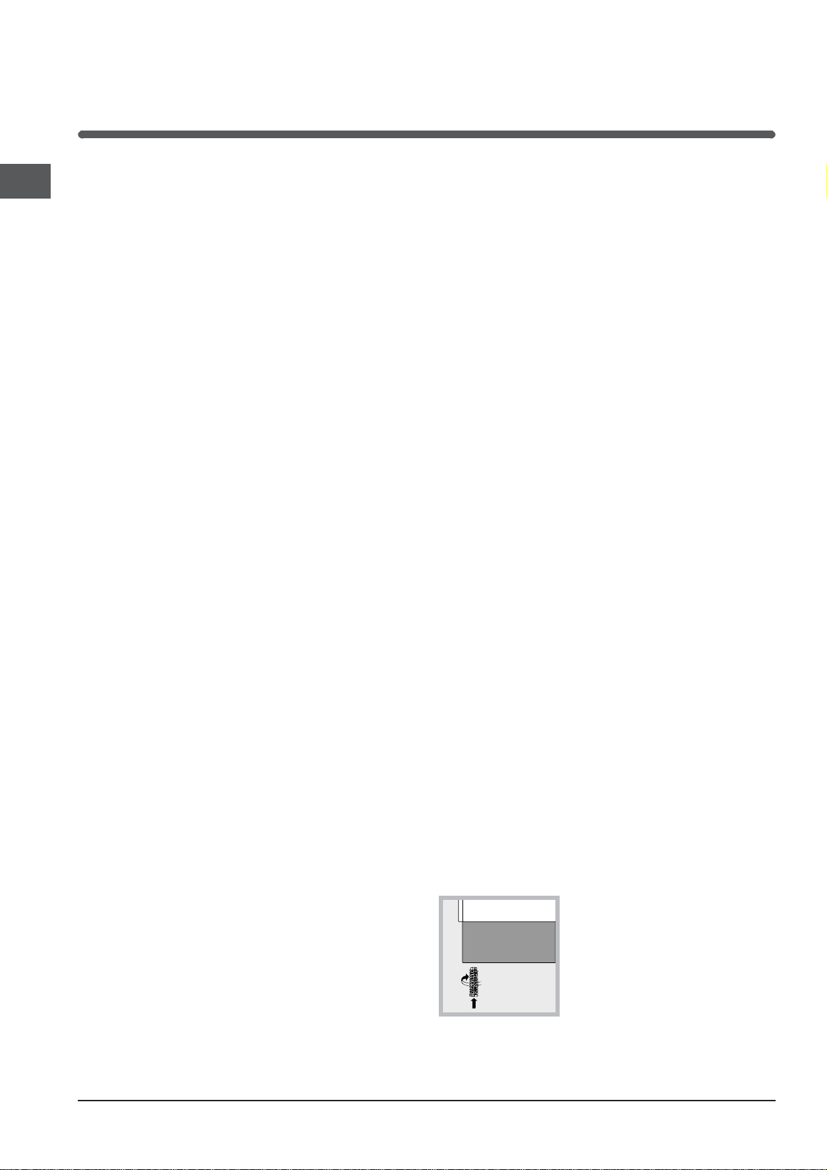
! When you place the rack inside,
make sure that the stop is directed
upwards and in the back of the cavity.
2
The legs* fit into the slots on
HOOD
420
Min.
min.
650
mm. with hood
min.
700
mm. without hood
mm.
600
Min. mm.
420
Min. mm.
700 mm
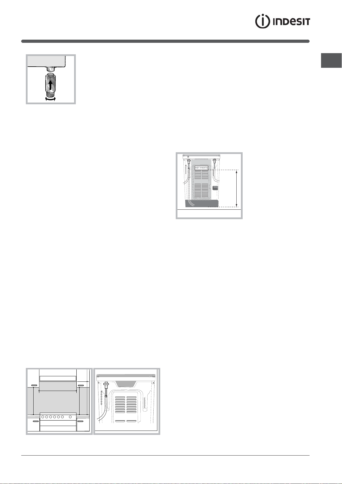
HOT PARTS
The appliance must not be installed behind
a decorative door in order to avoid overheating
the underside of the base of
the cooker.
Installation of the cooker
The appliance can be installed next to furniture units
which are no taller than the top of the cooker hob.
The wall in direct contact with the back panel of the
cooker must be made of non-flammable material.
During operation the back panel of the cooker could
reach a temperature of 50°C above room
temperature. For proper installation of the cooker,
the following precautions must be taken:
a)a)
a )The appliance can be placed in a kitchen, dining
a)a)
room or bedsit, but not in a bathroom.
b)b)
b )All furniture around the appliance must be placed
b)b)
at least 200 mm from the top of the cooker,
should the surface of the appliance be higher than
the worktop of this furniture. Curtains should not
be placed behind the cooker or less than 200 mm
away from the sides of the appliance.
c)c)
c )Any hoods must be installed according to the
c)c)
requirements in the installation manual for the
hoods themselves.
d)d)
d )If the cooker is installed beneath a wall cabinet,
d)d)
the latter must be situated at a minimum of 420
mm above the hob. The minimum distance
between the worktop and kitchen units made of
combustible material is 700 mm (Fig. A).
e)e)
e )The wall in direct contact with the back panel of
e)e)
the cooker must be made of non-flammable
materials.
f)f)
f ) The cooker is fitted with a safety chain that must
f)f)
be attached to a hook, secured to the wall behind
the appliance.
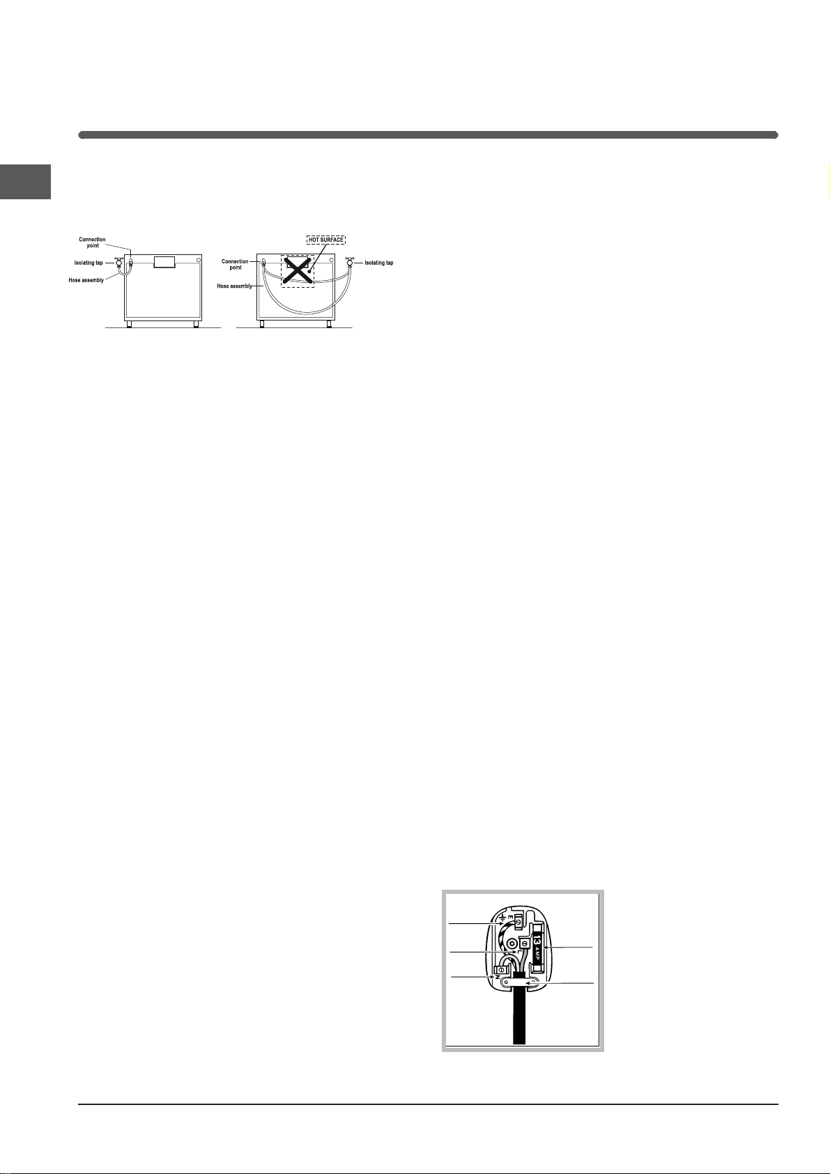
! Some models can have their gas connection
inverted. It is important to make sure the safety
chain is always situated on the side which
corresponds to the hose holder (Fig. B).
Gas connection
T he cooker should be connected to the gas-supply
by a corgi registered installer. During installation of
this product it is essential to fit an approved gas tap
to isolate the supply from the appliance for the
convenience of any subsequent removal or
servicing. Connection of the appliance to the gas
mains or liquid gas must be carried out according to
the prescribed regulation in force, and only after it is
ascertained that it is adaptable to the type of gas to
be used. If not, follow the instructions indicated in
the paragraph headed “Adaptation to different gas
types”. On some models the gas supply can be
connected on the left or
on the right, as
necessary; to change
the connection, reverse
the position of the hose
holder with that of the
cap and replace the
gasket (supplied with
the appliance). In the
case of connection to
liquid gas, by tank, use
pressure regulators that conform to the regulation in
force. The gas supply must be connected to the left
of the appliance. Be sure that the hose does not
pass through the rear of the cooker touching hot
parts.
! Make sure the supply pressure conforms with the
values shown in the table entitled “Caracteristics of
the burners and nozzles”.
installed between cabinets (recessed), theinstalled between cabinets (recessed), the
installed between cabinets (recessed), the
installed between cabinets (recessed), theinstalled between cabinets (recessed), the
gas connection must be effected by angas connection must be effected by an
gas connection must be effected by an
gas connection must be effected by angas connection must be effected by an
approved flexible hose with bayonet fittingapproved flexible hose with bayonet fitting
approved flexible hose with bayonet fitting
approved flexible hose with bayonet fittingapproved flexible hose with bayonet fitting
(BS 669 Current Edition). The gas inlet for(BS 669 Current Edition). The gas inlet for
(BS 669 Current Edition). The gas inlet for
(BS 669 Current Edition). The gas inlet for(BS 669 Current Edition). The gas inlet for
the cookers is a threaded G 1/2 gas femalethe cookers is a threaded G 1/2 gas female
the cookers is a threaded G 1/2 gas female
the cookers is a threaded G 1/2 gas femalethe cookers is a threaded G 1/2 gas female
fitting.fitting.
fitting.
fitting.fitting.
Connecting the gas supply
To make the connection, a flexible hose should be
used corresponding to the current gas regulations
which are:
• the hose must never be at any point in its lenght
in contact with the “hot” parts of the cooker;
• the hose must never be longer than 1,5 metre;
• the hose must not be subject to any tension or
torsional stress and it must not have any
excessively narrow curves or bottlenecks;
• the hose must be easy to inspect along its entire
length to check its condition;
• the hose must always be in good condition, never
attempt to repair.
When the cooker isWhen the cooker is
When the cooker is
When the cooker isWhen the cooker is
GB
Fig. A Fig. B
3
GB
GREEN &
YELLOW
BROWN
BLUE
13 amp fuse
CROSS-BAR
CORD GRIP
! The installation must comply with gas safety
(installation and use) regulations 1984. In all cases
for the above, by low, a qualified, corgi approved
engineer must be called for installation.
Electrial connection
Power supply voltage and frequency: 230-240V a.c.
50/60 Hz.
!!
! The supply cable must be positioned so that it
!!
never reaches at any point a temperature 50°C
higher than the room temperature. The cable must
be routed away from the rear vents. Should you
require it, you may use a longer cable, however, you
must ensure that the cable supplied with the
appliance is replaced by one of the same
specifications in accordance with current standards
and legislation.
Your appliance is supplied with a 13 amp fused plug
that can be plugged into a 13 amp socket for
immediate use. Before using the appliance please
read the instructions below.
WARNING - THIS APPLIANCE MUST BE
EARTHED.
THE FOLLOWING OPERATIONS SHOULD BE
CARRIED OUT BY A QUALIFIED ELECTRICIAN.
Replacing the fuse:
When replacing a faulty fuse, a 13 amp ASTA
approved fuse to BS 1362 should always be used,
and the fuse cover re-fitted. If the fuse cover is lost,
the plug must not be used until a replacement is
obtained.
Replacement fuse covers:
If a replacement fuse cover is fitted, it must be of
the correct colour as indicated by the coloured
marking or the colour that is embossed in words on
the base of the plug. Replacements can be obtained
directly from your nearest Service Depot.
• the mains cable is wired directly into a 13 amp
cable outlet, controlled by a switch, (in
compliance with BS 5733) which is accessible
without moving the appliance.
!!
! For appliances with a rating greater than 13 amp
!!
(eg: electric hob, double ovens and freestanding
electric cookers etc.) the mains cable must be wired
into a cooker output point with a rating of 45 amp. In
this case the cable is not supplied.
Disposing of the plug:
Ensure that before disposing of the plug itself, you
make the pins unusable so that it cannot be
accidentally inserted into a socket. Instructions for
connecting cable to an alternative plug:
!!
! The wires in the mains lead are coloured in
!!
accordance with the following code:
Green & Yellow - Earth
Blue - Neutral
Brown - Live
If the colours of the wires in the mains lead do not
correspond with the coloured markings identifying
the terminals in your plug, proceed as follows:
EE
Connect Green & Yellow wire to terminal marked “
E”
EE
or or coloured Green or Green & Yellow.
LL
Connect Brown wire to terminal marked “
L” or
LL
coloured Red.
NN
Connect Blue wire to terminal marked “
N” or
NN
coloured Black.
If a 13 amp plug (BS 1363) is used it must be fitted
with a 13 amp fuse. A 15 amp plug must be
protected by a 15 amp fuse, either in the plug or
adaptor or at the distribution board. If you are in any
doubt about the electrical supply to your machine,
consult a qualified electrician before use.
How to connect an alternative plug:
The wires in this mains lead are coloured in
accordance with the following code:
BLUE
BLUE
BLUE “
BLUEBLUE
BROWNBROWN
BROWN “
BROWNBROWN
GREEN AND YELLOWGREEN AND YELLOW
GREEN AND YELLOW “
GREEN AND YELLOWGREEN AND YELLOW
NEUTRALNEUTRAL
NEUTRAL” (“
NEUTRALNEUTRAL
LIVELIVE
LIVE” (“
LIVELIVE
EARTHEARTH
EARTH” (“
EARTHEARTH
LL
L”)
LL
EE
E”)
EE
NN
N”)
NN
Removing the plug:
If your appliance has a non-rewireable moulded plug
and you should wish to remove it to add a cable
extension or to re-route the mains cable through
partitions, units etc., please ensure that either:
• the plug is replaced by a fused 13 amp rewireable plug bearing the BSI mark of approval.
or:
4
Disposing of the appliance
When disposing of the appliance please remove the
plug by cutting the mains cable as close as
possible to the plug body and dispose of it as
described above.
Checking the connection for leaks
When the installation process is complete, check
the hose fittings for leaks using a soapy solution.
Never use a flame.
Adapting to different types of gas
It is possible to adapt the appliance to a type of gas
other than the default type (this is indicated on the
rating label on the cover).
Adapting the hob
Replacing the nozzles for the hob burners:
1. Remove the hob grids and
slide the burners off their
seats.
2. Unscrew the nozzles using
a 7 mm socket spanner (
figure
), and replace them with
nozzles suited to the new type
of gas (
specifications table
3. Replace all the components by following the
above instructions in reverse.
Adjusting the hob burners’ minimum setting:
1. Turn the tap to the minimum position.
2. Remove the knob and adjust the regulatory
screw, which is positioned inside or next to the tap
pin, until the flame is small but steady.
! If the appliance is connected to a liquid gas
supply, the regulatory screw must be fastened as
tightly as possible.
).
see Burner and nozzle
see
! The hob burners do not require primary air adjustment.
! After adjusting the appliance so it may be used
with a different type of gas, replace the old rating
label with a new one that corresponds to the new
type of gas (these labels are available from
Authorised Technical Assistance Centres).
! Should the gas pressure used be different (or vary
slightly) from the recommended pressure, a suitable
pressure regulator must be fitted to the inlet hose in
accordance with current national regulations relating
to “regulators for channelled gas”.
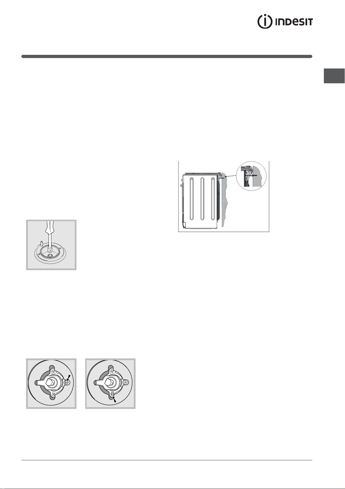
Safety Chain
! In order
to prevent
accidental
tipping of the
appliance, for
example by
a child climbing onto the
oven door, the
supplied safety
chain MUST be
installed!
The cooker is fitted with a safety chain to be fixed by
means of a screw (not supplied with the cooker) to
the wall behind the appliance, at the same height as
the chain is attached to the appliance.
Choose the screw and the screw anchor according
to the type of material of the wall behind the appliance. If the head of the screw has a diameter smaller
than 9mm, a washer should be used. Concrete wall
requires the screw of at least 8mm of diameter, and
60mm of length.
Ensure that the chain is fixed to the rear wall of the
cooker and to the wall, as shown in figure, so that
after installation it is tensioned and parallel to the
ground level.
GB
3. While the burner is alight, quickly change the position
of the knob from minimum to maximum and vice versa
several times, checking that the flame is not
extinguished.
5
 Loading...