


DIMNS 53 KC.A IX GB
English
Operating Instructions
OVEN
Operating Instructions,1
Warnings,2
Description of the appliance,3
Installation,4
Start-up and use,6
Cooking modes,6
The electronic programmer,8
Precautions and tips,9
Maintenance and care,10
Afetr Sales Service,11
Guarantee,12
Contents
08448 24 24 24
Please phone us on
guarantee
to activate your
PLEASE PHONE US TO REGISTER YOUR APPLIANCE AND ACTIVATE YOUR PARTS GUARANTEE ON 08448 24 24 24
Warnings
WARNING: The appliance and its accessible parts
become hot during use. Care should be taken to
avoid touching heating elements. Children less than 8
years of age shall be kept away unless continuously
supervised. This appliance can be used by children
aged from 8 years and above and persons with
reduced physical, sensory or mental capabilities or
lack of experience and knowledge if they have been
given supervision or instruction concerning use of the
appliance in a safe way and understand the hazards
involved. Children shall not play with the appliance.
Cleaning and user maintenance shall not be made
by children without supervision.
Do not use harsh abrasive cleaners or sharp metal
scrapers to clean the oven door glass since they can
scratch the surface, which may result in shattering
of the glass.
Never use steam cleaners or pressure cleaners on
the appliance.
WARNING: Ensure that the appliance is switched
off before replacing the lamp to avoid the possibility
of electric shock.
! When you place the rack inside, make sure that the
stop is directed upwards and in the back of the cavity.
2
PLEASE PHONE US TO REGISTER YOUR APPLIANCE AND ACTIVATE YOUR PARTS GUARANTEE ON 08448 24 24 24
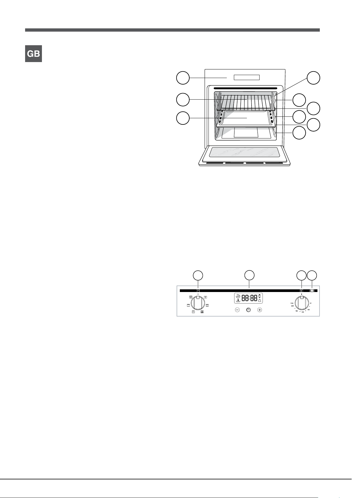
Description of the appliance
7
1
3
4
5
Overall view
1 POSITION 1
2 POSITION 2
3 POSITION 3
4 POSITION 4
5 POSITION 5
6 GUIDES for the sliding racks
7 DRIPPING PAN
8 GRILL
9 Control panel
9 6
8
2
Control panel
1 SELECTOR knob
2 ELECTRONIC programmer
3 THERMOSTAT knob
4 THERMOSTAT indicator light
2
3 41
3
PLEASE PHONE US TO REGISTER YOUR APPLIANCE AND ACTIVATE YOUR PARTS GUARANTEE ON 08448 24 24 24
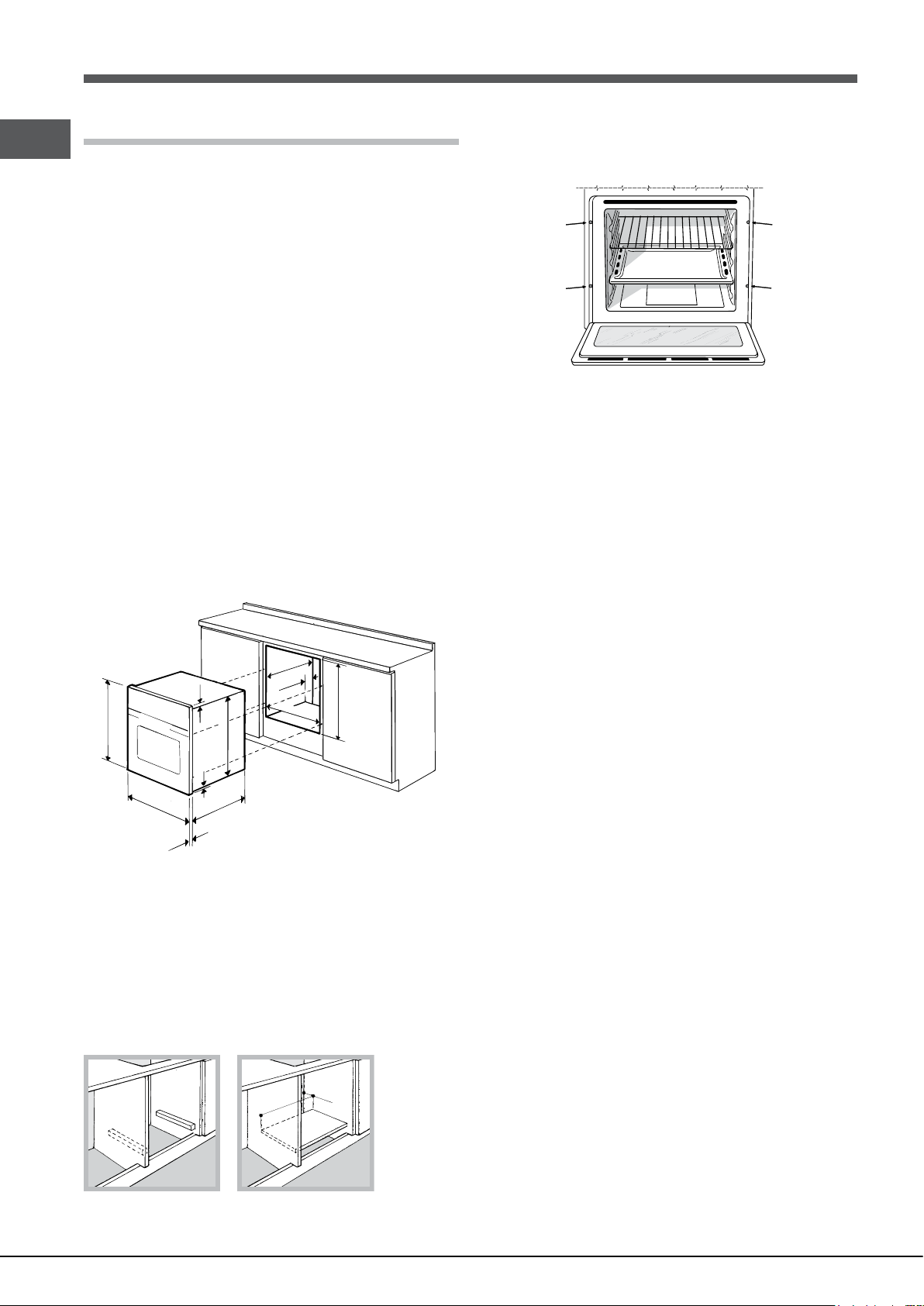
Installation
595 mm.
25 mm.
GB
! Please keep this instruction booklet in a safe place for future reference. If
the appliance is sold, given away or moved, please make sure the booklet is
also passed on to the new owners so that they may benet from the advice
contained within it.
! Please read this instruction manual carefully: it contains important information
concerning the safe operation, installation and maintenance of the appliance.
Positioning
! Do not let children play with the packaging material; it should be disposed
of in accordance with local separated waste collection standards (see
Precautions and tips).
Centring and xing
Secure the appliance to the cabinet by opening the oven door and inserting
4 screws into the 4 holes on the outer frame.
! The appliance must be installed by a qualied professional in accordance
with the instructions provided. Incorrect installation may damage property or
! All parts which ensure the safe operation of the appliance must not be
removable without the aid of a tool.
cause harm to people or animals.
Electrical connection
Built-in appliances
Use an appropriate cabinet to ensure that the appliance operates properly:
• The panels adjacent to the oven must be made of heat-resistant material.
• Cabinets with a veneer exterior must be assembled with glues which can
withstand temperatures of up to 100°C.
• To install the oven under the counter (see diagram) or in a kitchen unit,
the cabinet must have the following dimensions:
547 mm. min.
23 mm.
5 mm.
595 mm.
545 mm.
45 mm.
560 mm.
575-585 mm.
567 mm.
Ovens equipped with a three-pole power supply cable are designed to operate
with alternating current at the voltage and frequency indicated on the data
plate located on the appliance (see below).
Two types of connection are provided:
Connection n° 1
Connecting the supply cable to the mains
Install a standardised plug corresponding to the load indicated on the data
plate (see table).
The appliance must be directly connected to the mains using an omnipolar
switch with a minimum contact opening of 3 mm installed between the
appliance and the mains. The switch must be suitable for the charge indicated
and must comply with current electrical regulations (the earthing wire must not
be interrupted by the switch). The supply cable must be positioned so that it
does not come into contact with temperatures higher than 50°C at any point
(the back panel of the oven, for example).
! The installer must ensure that the correct electrical connection has been
performed and that it is fully compliant with safety regulations.
Before connecting the appliance to the power supply, make sure that
! The appliance must not come into contact with electrical parts once it has
been installed. The indications for consumption given on the data plate have
been calculated for this type of installation.
• The appliance is earthed and the plug is compliant with the law.
• The socket can withstand the maximum power of the appliance, which is
indicated on the data plate.
• The voltage is in the range between the values indicated on the data plate.
Ventilation
To ensure adequate ventilation, the back panel of the cabinet must be
removed. It is advisable to install the oven so that it rests on two strips of
• The socket is compatible with the plug of the appliance. If the socket is
incompatible with the plug, ask an authorised technician to replace it. Do
not use extension cords or multiple sockets.
wood, or on a completely at surface with an opening of at least 45 x 560
mm (see diagrams).
! Once the appliance has been installed, the power supply cable and the
electrical socket must be easily accessible.
45 mm.
560 mm.
! The cable must not be bent or compressed.
! The cable must be checked regularly and replaced by authorised technicians
only (see Assistance).
4
! The manufacturer declines any liability should these safety measures
not be observed.
PLEASE PHONE US TO REGISTER YOUR APPLIANCE AND ACTIVATE YOUR PARTS GUARANTEE ON 08448 24 24 24
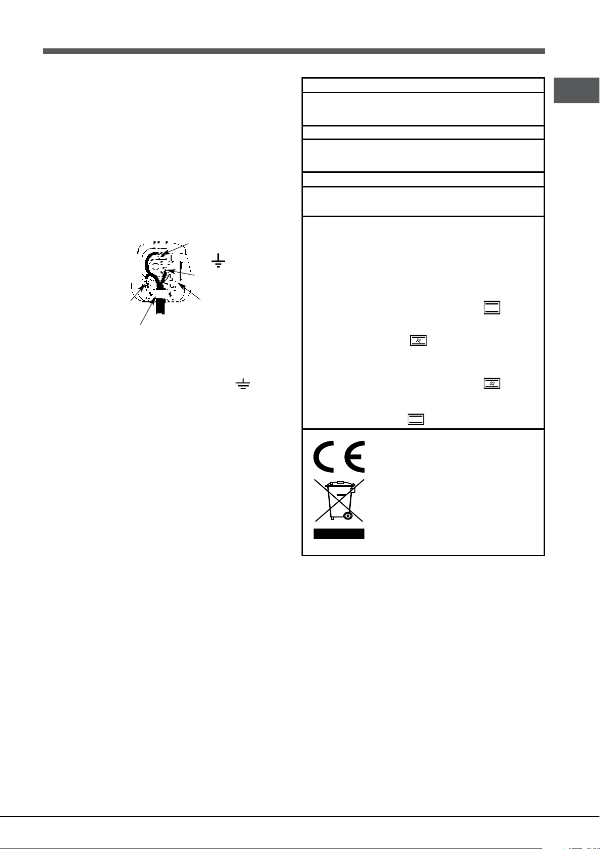
Connection n° 2
Green &
Blue
Neutral
Clamp
APPLIANCE SPECIFICATIONS
Dimensions*
width 43.5 cm
height 32,4 cm
depth 40.6 cm
Volume*
58 l
Dimensions**
width 45.5 cm
height 32,4 cm
depth 40.6 cm
Volume**
60 l
Electrical
connections
Voltage: 230 - 240 V~ 50/60 Hz
(see data plate) maximum power
absorbed 2250-2400 W
* Only for models with drawn rails.
** Only for models with wire rails.
This appliance conforms to the
following European Economic
Community directives:
- 2006/95/EC dated 12/12/06 (Low
Voltage) and subsequent amendments.
- 2004/108/EC dated 03/05/89
(Electromagnetic Compatibility) and
subsequent amendments.
- 93/68/EEC dated 22/07/93 and
subsequent amendments.
- 2012/19/EU and subsequent
amendments.
- 1275/2008 standby/off mode.
Models with cooling ventilation:
Energy consum ption for Natural
convection heating mode:
Convection
Declared energy consumption for
Forced convection Class heating
mode: Multi-cooking
Models without cooling
ventilation
Energy consum ption for Forced
convection heating mode:
Multi-cooking
Declared energy consumption for
Natural convection Class heating
mode: Convection
EU Directive no 65/2014
supplementing Directive 2010/30/EU.
EU Regulation no 66/2014
implementing Directive 2009/125/EC.
Standard EN 60350-1
Standard EN 50564
ENERGY
LABEL e
ECODESIGN
IF THE FITTED PLUG IS REMOVED
The exible mains lead must be correctly connected as below to a three pin
plug of not less than 13 amp capacity. If a B.S. 1363 fused plug is used, it
must be tted with a fuse which is approved to B.S. 1362.
Important: the wires in the mains lead are coloured in accordance with the
following code:
Green & Yellow - Earth
Blue - Neutral
Brown - Live
The power supply cable must be type H05VV-F
Yellow to
Earth
Brown
to Live
GB
As the colours of the wires in the mains lead may not correspond with the
coloured markings identifying the terminals in your plug, proceed as follows:
Connect the Green & Yellow wire to terminal marked “E” or
Green or Green & Yellow.
Connect the Brown wire to the terminal marked “L” or coloured Red.
Connect the Blue wire to the terminal marked “N” or coloured Black.
FAILURE TO OBSERVE THE ACCIDENT-PREVENTION REGULATIONS
RELIEVES THE MANUFACTURER OF ALL LIABILITY.
IF A MOULDED PLUG IS FITTED
In the event of replacing a fuse in the plug supplied an ASTA approved fuse
to BS1362 must be tted.
NOTE: The fuse cover must be retted when changing the fuse. In the event
of losing the fuse cover the plug must not be used until a replacement fuse
cover has been obtained and tted. A new fuse cover can be obtained from
your local Electricity Board. The colour of the correct replacement fuse cover
is that of the coloured marks or inserts in the base of the plug.Make sure that
the cable does not become trapped when pushing the cooker into position.
Replacing the cable
Use a rubber cable of the type H05VV-F with a cross section of 3 x 1.5 mm².
The yellow-green earth wire must be 2 ÷ 3 cm longer than the other wires.
to
Cord
3 Amp
Fuse
or coloured
5
 Loading...