


 Loading...
the art of ventilation
User Manual bellavista Ventilator
User Manual bellavista Ventilator
Thank you very much for choosing bellavista. You have purchased a top-quality ventilator that meets the highest standards.

imtmedical ag Gewerbestrasse 8 9470 Buchs (SG) Switzerland
sales@imtmedical.com
Table of Contents
1 Introduction |
7 |
|
1.1 |
Intended use |
7 |
1.2 |
Supported ventilation modes |
7 |
1.3 |
Validity of this User Manual |
8 |
1.4 |
Technical support |
8 |
2 Important safety instructions |
9 |
|
2.1 |
Legend |
9 |
2.2 |
Liability |
9 |
2.3 |
Introduction |
9 |
2.4 |
Storing the documentation |
9 |
2.5 |
Training documentation |
9 |
2.6 |
Staff qualification |
9 |
2.7 |
Correct User Manual |
9 |
2.8 |
Use of a functional bellavista |
9 |
2.9 |
Working safely with bellavista |
10 |
2.10 |
Contraindications |
10 |
2.11 |
Note about potential errors |
10 |
2.12 |
Start-up |
11 |
2.13 |
Setting up ventilation |
15 |
2.14 |
Stopping ventilation, shutdown |
16 |
2.15 |
Servicing and maintenance |
16 |
2.16 |
Transport |
16 |
3 Description of the device |
17 |
|
3.1 |
Overview of bellavista 1000 |
17 |
3.2 |
Overview of bellavista neo |
18 |
3.3 |
Overview of bellavista 1000 e |
19 |
3.4 |
System overview |
20 |
3.5 |
Air and oxygen supply |
20 |
4 Preparing for ventilation |
21 |
|
4.1 |
Checking delivery |
21 |
4.2 |
First steps |
21 |
4.3 |
Connecting supply lines |
22 |
4.4 |
Battery operation |
23 |
4.5 |
Oxygen connector |
24 |
4.6 |
Inlet filter |
25 |
4.7 |
Switching on bellavista |
26 |
4.8 |
Start screen |
26 |
4.9 |
Selecting the breathing circuit |
28 |
4.10 |
Selecting the patient type |
28 |
4.11 |
Safety instructions about breathing circuits |
28 |
4.12 |
Connecting the breathing circuit |
29 |
4.13 |
Connecting the humidifier |
30 |
4.14 |
Connecting the patient |
31 |
4.15 |
Flow sensor |
31 |
4.16 |
Connecting the nebuliser |
32 |
4.17 |
Dual limb adapter |
34 |
4.18 |
Integrated expiratory valve |
34 |
4.19 |
Capnography CO2 respiratory gas sensors |
35 |
4.20 |
SpO2 pulse oximeter |
36 |
5 |
NIV, non-invasive ventilation |
39 |
|
6 |
Ventilation of neonates |
41 |
|
7 |
Operation |
43 |
|
|
7.1 |
Index of applications |
44 |
|
7.2 |
Changing the monitoring settings |
46 |
|
7.3 |
Changing the curve display |
47 |
|
7.4 |
Zooming gestures |
48 |
|
7.5 |
Safety-protected settings |
48 |
|
7.6 |
Login, user level |
49 |
|
7.7 |
Configuration Assist |
50 |
|
7.8 |
Data Assist |
51 |
|
7.9 |
iVista |
52 |
8 |
Setting up ventilation |
53 |
|
|
8.1 |
Making ventilation settings |
53 |
|
8.2 |
beMode Assist |
54 |
|
8.3 |
Starting ventilation (ventilation menu) |
59 |
|
8.4 |
Introduction to the ventilation modes |
60 |
|
8.5 |
ATC Automatic Tube Compensation |
64 |
|
8.6 |
PLV Pressure Limited Ventilation |
64 |
|
8.7 |
Sigh |
65 |
|
8.8 |
Ramp |
66 |
|
8.9 |
CPAP |
67 |
|
8.10 |
nCPAP |
68 |
|
8.11 |
nIPPV |
69 |
|
8.12 |
PCV |
70 |
|
8.13 |
P-A/C |
70 |
|
8.14 |
T |
70 |
|
8.15 |
PC-SIMV |
71 |
|
8.16 |
PSV |
72 |
|
8.17 |
S |
72 |
|
8.18 |
S/T |
72 |
|
8.19 |
beLevel |
73 |
|
8.20 |
APRV |
74 |
|
8.21 |
VCV |
75 |
|
8.22 |
V-A/C |
75 |
|
8.23 |
VC-SIMV |
76 |
|
8.24 |
AVM |
77 |
|
8.25 |
HFOT |
78 |
9 |
During ventilation |
81 |
|
|
9.1 |
Monitoring |
81 |
|
9.2 |
Cockpit |
81 |
|
9.3 |
Lung Recruitment Tool |
82 |
|
9.4 |
Hold manoeuvre |
87 |
|
9.5 |
Esophageal pressure monitoring |
87 |
|
9.6 |
Chameleon |
88 |
|
9.7 |
Trending |
89 |
|
9.8 |
Alarms |
89 |
10 |
Stopping ventilation, shutdown |
91 |
|
|
10.1 |
bellavista shutdown |
92 |
11 |
Servicing and maintenance |
93 |
|
|
11.1 |
Factory repair |
93 |
|
11.2 |
Changing fuses |
93 |
|
11.3 |
Batteries |
93 |
|
11.4 |
Disposal |
93 |
|
11.5 |
Reprocessing,cleaning,disinfection |
94 |
|
11.6 |
Calibration Assist |
95 |
12 |
Specifications |
97 |
|
|
12.1 |
Standards |
97 |
|
12.2 |
Classification |
97 |
|
12.3 |
Device data |
98 |
|
12.4 |
Ambient conditions |
99 |
|
12.5 |
Units and languages |
99 |
|
12.6 |
Pressure, flow |
99 |
|
12.7 |
Connection data |
100 |
|
12.8 |
Trending |
101 |
|
12.9 |
SpO2 pulse oximeter (optional) |
101 |
|
12.10 |
CO2 respiratory gas sensor (optional) |
101 |
|
12.11 |
Breathing circuit and flow sensor |
102 |
|
12.12 |
Drug nebuliser (optional) |
104 |
|
12.13 |
Noise generation |
105 |
|
12.14 |
Supported ventilation modes |
106 |
|
12.15 |
Ventilation settings |
107 |
|
12.16 |
Curves and loops |
111 |
|
12.17 |
Monitoring parameters |
113 |
|
12.18 |
Alarm limits |
119 |
|
12.19 |
Pneumatic block diagram |
120 |
|
12.20 |
Models accessories, consumables, spare parts |
121 |
|
12.21 |
Symbols on device and packaging |
124 |
13 |
Appendix |
127 |
|
|
13.1 |
Network / data sharing |
127 |
|
13.2 |
Start screen settings |
131 |
|
13.3 |
List of alarms |
135 |
|
13.4 |
Manufacturer's EMC declaration in accordance with EN60601-1-2:2007 |
143 |
|
13.5 |
ESD safety measures |
147 |
|
13.6 |
bellavista training certificate |
148 |
|
13.7 |
Servicing and maintenance checklist for bellavista |
151 |
|
13.8 |
bellavista quick check |
153 |
14 |
Index |
|
155 |
Passwords for bellavista ventilator |
159 |


1 Introduction
1.1Intended use
1.2Supported ventilation modes
Introduction
1
Welcome to bellavista. This User Manual will show you how to put your bellavista ventilator into operation and use all its functions.
The bellavista ventilator was developed for ventilating adult and paediatric patients and, optionally, neonatal patients as of a tidal volume of ≥ 2 mL 1. The device is intended for use in clinics and institutional facilities where medically trained professionals are available for attending to the patient. The device can be used at the bedside, as well as for transferral within a facility, when a patient is in need of oxygen.
bellavista is only intended for use by trained personnel under the supervision of a licensed doctor.
Carefully read the instruction for use before using bellavista. Use bellavista only if you are a trained professional.
This instruction for use only applies to the ventilator type and software version specified.
Abbreviation |
Description |
|
|
CPAP |
Continuous Positive Airway Pressure |
|
|
nCPAP |
Nasal Continuous Positive Airway Pressure |
|
|
nIPPV |
Nasal Intermittent Positive Pressure Ventilation |
|
|
PCV |
Pressure Controlled Ventilation |
|
|
P-A/C |
Pressure Assist / Control Ventilation |
|
|
PC-SIMV |
Pressure Controlled Synchronised Intermittent Mandatory Ventilation |
|
|
PSV |
Pressure Support Ventilation, Spontaneous |
|
|
S |
Spontaneous without backup rate |
|
|
S/T |
Spontaneous/timed with backup rate |
|
|
T |
Timed |
|
|
beLevel |
Biphasic ventilation at two pressure levels and additional pressure |
|
support |
|
|
APRV |
Airway Pressure Release Ventilation |
|
|
VCV |
Volume Controlled Ventilation |
|
|
V-A/C |
Volume Assist / Control Ventilation |
|
|
VC-SIMV |
Volume Controlled Synchronised Intermittent Mandatory Ventilation |
|
|
AVM |
Adaptive Ventilation Mode |
|
|
HFOT |
High Flow Oxygen Therapy |
|
|
beModes |
Special modes for Day / Night, DualVent, MaskFit, TargetVent, Apnea |
|
Backup ventilation |
|
|
TargetVent |
Pressure-regulated, volume-controlled ventilation mode |
|
|
1 Neonatal option not available in all countries.
imtmedical ag |
7 |

Introduction
1 |
1.3 |
Validity of this User Manual |
This User Manual applies to |
|
|
|
|
|
|
|
|
|
• |
bellavista 1000 (G6) |
|
|
|
|
SN: MB200000 and higher |
|
|
|
|
Software version 6.0 |
|
|
|
• bellavista 1000 neo (G6) |
|
|
|
|
|
SN: MB160000 and higher |
|
|
|
|
Software version 6.0 |
|
|
|
In the following document the device “bellavista 1000 neo” will be described with the |
|
|
|
|
following name: “bellavista neo”. |
|
|
|
|
• |
bellavista 1000 e (G6) |
|
|
|
|
SN: MB170000 and higher |
|
|
|
|
Software version 6.0 |
|
|
|
Where necessary, distinctions are made accordingly in this User Manual. |
|
|
1.4 |
Technical support |
Should you encounter any unexpected problems with bellavista, please notify your |
|
|
|
|
local distributor or contact imtmedical ag directly: |
|
|
|
|
Technical support |
|
|
|
|
• |
techsupport@imtmedical.com |
|
|
|
• |
https://www.imtmedical.com/Support/OpenTicket |
8 |
imtmedical ag |

Important safety instructions
2 |
Important safety instructions |
|
||
2.1 |
Legend |
|
|
|
Indicates a potential danger to life and limb. Or indicates a hazard |
|
|
||
|
|
that can cause damage to bellavista. |
|
2 |
|
|
|
|
|
|
|
|
|
|
|
|
|
|
|
|
|
Notes and measures with which operation of bellavista can be made easier |
|
|
|
|
and more efficient. |
|
|
|
|
|
|
|
|
|
Definition: |
|
|
|
|
The operator is the facility which, after purchase of the medical device, holds respon- |
|
|
|
|
sibility for operation of that device. |
|
|
2.2 |
Liability |
The manufacturer does not assume liability for any damage that occurs owing to |
|
|
|
|
non-compliance with this User Manual. The terms of warranty and liability contained |
|
|
|
|
in the manufacturer's terms and conditions of sale and delivery are not extended by |
|
|
|
|
the following provisions. |
|
|
|
|
If the device is not used as intended, liability for the performance of bellavista shall |
|
|
|
|
always pass to the owner or operator. |
|
|
|
|
Modifications to the device are prohibited. |
|
|
2.3 |
Introduction |
Read through the User Manual carefully before you put bellavista into operation. This |
|
|
|
|
User Manual only applies to the device types and software version referred to on the |
|
|
|
|
first pages. |
|
|
2.4Storing the documentation Always keep the documentation in a readily accessible place near bellavista.
2.5 |
Training documentation |
This User Manual serves as training documentation for teaching the main user control |
|
|
functions. |
2.6 |
Staff qualification |
bellavista is designed to be operated by qualified medical and technical personnel. |
|
|
After suitable instruction, the patient cockpit can be operated by persons without a |
|
|
medical qualification, e.g. patients and nursing staff. |
|
|
Liability for the performance of bellavista shall pass to the owner or operator if bel- |
|
|
lavista is improperly serviced or repaired by persons who are not authorised to do so |
|
|
by the manufacturer. |
2.7 |
Correct User Manual |
Make sure you have the appropriate User Manual that belongs with the device and |
|
|
the software to avoid any risk to the user, patient or device. |
2.8 |
Use of a functional |
If a defective bellavista is used, malfunctions may directly or indirectly endanger the |
|
bellavista |
patient's health. |
Before putting bellavista into operation, always check to make sure it is functioning properly. Never use bellavista if it has been found to be faulty. Have any defects repaired without delay.
imtmedical ag |
9 |
Important safety instructions
2.9 |
Working safely with |
Before each use of bellavista, perform a quick check. bellavista has to be repro- |
|
|
|
bellavista |
cessed after each use on a patient. Check the ventilation settings before connecting |
|
|
|
the patient up to bellavista. Check apnea backup settings carefully before activating |
2 |
|
|
backups. Adjust the alarm volume so that the alarm can be heard. Nurse call is only |
|
|
designed as an additional alarm. Check that it is working after installation. |
|
|
|
|
The patient monitoring system is also active when on standby so pneumatograms |
|
|
|
and measurements displayed are no indication of active ventilation by the device. |
|
|
|
Check the oxygen saturation and CO2 concentration in the blood regularly using |
|
|
|
pulse oximetry and capnography or blood gas analysis. |
|
|
|
Before using a defibrillator, remove the SpO2 pulse oximeter and CO2 capnography |
|
|
|
sensor from the patient or disconnect from the device. |
|
|
|
In non-invasive ventilation (NIV) the ventilator is intended to support a patient breath- |
|
|
|
ing spontaneously. It is not intended to ensure complete ventilation of a patient. |
|
|
|
A change in the patient's position may make it necessary to adjust the ventilator |
|
|
|
settings. Make sure the patient is properly supplied at all times and that lung damage |
|
|
|
and mistriggering are avoided. |
|
• Check tidal volume and minute volume. |
|
• Check the ventilation pressures. |
|
• Adjust the ventilation pressure if necessary. |
|
• Check the trigger reaction. |
|
• Adjust the trigger settings. |
|
• Always adapt the alarm limits to any new ventilation settings. |
|
Only use your fingers to operate the touch screen. Pointed objects can damage the |
|
touch screen. |
2.10 Contraindications |
• Complications with airway intubation |
•Complications from positive pressure ventilation
•Barotrauma
•Oxygen toxicity
•Cardiovascular complications
•Breathing effort and patient-respirator asynchrony
•Adverse effects of sedation and paralysis
•Other disease-related complications
2.11Note about potential errors If you have any concerns about the performance or the behaviour of bellavista, you
should take it out of service without delay. Please report your observations with respect to potential errors or ambiguities in bellavista or the accompanying documentation. The safety of the patient being ventilated is the responsibility of the attending physician or nursing staff. Their judgement takes priority over the content of this User Manual. Always ensure that appropriate measures are taken to adequately monitor the patient.
10 |
imtmedical ag |

Important safety instructions
2.12 Start-up |
Only use earthed cables in order to avoid the risk of an electric shock. |
|
|
|
Do not use: |
|
|
|
2 |
||
|
• a power cord set longer than 3 m |
||
|
|
||
|
|
||
|
• a defective power cord set |
|
|
|
• a power cord set that is not earthed |
|
|
|
• extension cables |
|
|
|
• double plugs or adapters |
|
|
|
Keep the power cord set away from the patient to avoid strangulation. Keep the power |
|
|
|
supply accessible to make it possible to disconnect the device from the mains if neces- |
|
|
|
sary. |
|
|
|
The absence of a ventilation alternative such as a self-priming, user-operated resus- |
|
|
|
citator with a breathing mask (ventilation bag as specified in ISO 10651-4) can lead |
|
|
|
to the patient's death if the ventilator fails. |
|
|
|
If there are concerns about the condition or set-up of the earth wire, bellavista may |
|
|
|
only be operated in battery mode. |
|
|
|
Earthing is only reliable if the device is plugged into a socket marked as being suitable |
|
|
|
for medical equipment. |
|
|
|
|
|
|
|
Breathing circuit C must not be used for life-supporting ventilati- |
|
|
|
on owing to the absence of expiratory volume monitoring. |
|
|
|
|
|
|
|
Avoid occlusion of the expiratory valve. |
|
|
|
Omitting a bacterial filter or using an incorrect bacterial filter can bring about trans- |
|
|
|
mission of pathogens to the patient and contamination of bellavista. |
|
|
|
Change the bacterial filter according to the manufacturer’s instructions and before |
|
|
|
each new patient. Used filters must be disposed of as medical waste. |
|
|
|
To avoid electric shocks to the patient and/or user, refrain from using antistatic or |
|
|
|
electrically conductive tubes or lines. |
|
|
|
Additional accessories in the breathing circuit can significantly increase the flow resist- |
|
|
|
ance or dead space volume and, as a result, negatively impact ventilation performance. |
|
|
|
Comply with the instructions provided by the manufacturer of the humidifier in order |
|
|
|
to prevent exposure of the patient to a hazard and damage to bellavista. Place the |
|
|
|
humidifier at a lower level than bellavista and the patient in order to prevent aspiration |
|
|
|
of water and flooding of bellavista. |
|
|
Calibrate flow sensor in the event of
•a new patient
•a new flow sensor
•“Calibrate flow sensor” alarm
In the case of non-invasive ventilation, the expiratory measurements of volumes and capnography values can differ considerably from the actual expiration on account of leakage.
imtmedical ag |
11 |

Important safety instructions
2
2.12.1Installation and ambient conditions
The installations for supplying power to bellavista must be earthed and must comply with the applicable standards.
Any external DC power supply must comply with IEC 60601-1 or IEC 60950-1 providing 2 MOOP between primary and secondary circuit and be of class II without functional earth.
Use oxygen only in well ventilated rooms. Not in hazardous areas or near/with combustible materials or gases. bellavista batteries and accessories must not be operated in an explosive environment or in the vicinity of combustible materials or gases.
bellavista must not be used for combustible mixtures of anaesthetic gases or anaesthetic agents with air or oxygen and/or nitrous oxide.
bellavista must never be operated in areas subject to splashing (e.g. near bath tubs, showers) or in the vicinity of an open flame (e.g. candle).
Do not cover bellavista and do not position it such that the openings for suctioning patient air or the device fan are covered or blocked (risk of overheating, inadequate supply to the patient).
Do not place vessels filled with liquid or any other objects on top of bellavista.
In order to avoid accidental excessive supply of oxygen to the patient, do not use bellavista in the vicinity of free-flowing oxygen.
Place bellavista in an upright position so that it cannot tip over.
bellavista has been tested for electromagnetic interference in accordance with the EN 60601-1-2 standard. Operation of bellavista can be influenced by electromagnetic interference. bellavista must therefore not be operated in the vicinity of magnetic resonance imaging scanners, mobile phones or any other potentially disruptive devices or systems, for example.
To avoid interference with bellavista, please refer to the tables in the appendix: Manufacturer's EMC declaration in accordance with EN 60601-1-2.
Do not position bellavista too close to other equipment or place it on top of other equipment.
Do not expose bellavista to ionising radiation. It must therefore not be used in the vicinity of devices that generate diagnostic or therapeutic radiation (X-ray equipment, radiotherapy devices).
bellavista must not be used in the vicinity of devices that generate diagnostic or therapeutic sound pressure.
bellavista is not a portable device and must not be used while being carried.
Do not use bellavista in a hyperbaric chamber (pressurised chamber).
12 |
imtmedical ag |

Important safety instructions
2.12.2Connecting up to oxygen
Use medical oxygen only. Do not connect nitrogen oxide, helium, heliox or other gases. To avoid inadequate or excessive supply of oxygen, use the bellavista oxygen monitoring system and alarm options. The use of oxygen can lead to serious compli- 2 cations. The impact on the processes of peripheral and cerebral respiratory control
can cause respiratory pauses.
Use clean, intact oxygen tubing. Open the flow valve of the oxygen cylinder slowly and only when you have connected up the oxygen cylinder. An oxygen leak in the O2 supply or in bellavista can lead to a fire risk or an inadequate supply of oxygen to the patient.
Check the system regularly for leaks. In the event of a leak, turn off the oxygen source immediately. Use oxygen only in well ventilated rooms.
Do not use bellavista in the MR environment.
2.12.3Accessories, combination with other devices
The operator is responsible for ensuring that bellavista is only operated with accessories approved for it. The use of non-approved accessories or cables can:
•jeopardise the safety of the patient and/or user
•have a negative impact on the proper functioning of bellavista
•reduce performance
•have a negative impact on EMC protection
•lead to non-compliance with legal regulations.
Combination with devices that are not mentioned in this User Manual is only permissible in agreement with the manufacturers.
Ventilation modes nCPAP and nIPPV may only be used with a compatible nasal interface, in order to ensure correct alarms.
Do not reuse single-use accessories because this can lead to a detrimental effect on sterility, functionality and general performance. Do not use antistatic breathing circuits!
imtmedical ag |
13 |

Important safety instructions
2
2.12.4Nebulisation
Do not use a nebuliser together with the capnography sensor (risk of incorrect measurements). During nebulisation do not use any expiratory or HME filters.
Installation of a nebuliser between the Y-piece (or expiratory valve) and the patient increases dead space ventilation. Only nebulise medicinal products approved for nebulisation.
Check and clean, or replace the expiratory valve on a regular basis. Nebulisation can affect expiratory valve performance. Also bear in mind that nebulisation has an impact on the concentration of oxygen administered.
2.12.5External sensors (SpO2 and CO2)
According to EN/ISO 80601-2-12 bellavista must be provided, before start-up, with a monitoring device for measuring the expiratory carbon dioxide concentration in compliance with ISO 80601-2-55, e.g. in the expiratory section of the breathing circuit or at the patient port.
Only use the sensor in combination with other methods when monitoring the vital functions of a patient. Only use the sensor on a patient if you have the necessary expertise. Always bear in mind the dead space volume of the capnography airway adapter.
Do not use the sensor in conjunction with flammable anaesthetic gases.
•Do not autoclave the sensor or immerse it in a liquid.
•Do not pull on the sensor cable.
•Comply with the operating temperature range.
2.12.6Communication interface
The data supplied via a network / data sharing system is provided for reference purposes only. Decisions on patient treatment should be made by the clinician on the basis of patient observation.
In the event of an alarm, check the patient and bellavista on the spot immediately because not all alarms are displayed in detail in the network / data sharing system. Only use recommended connecting cables. The devices connected must be approved medical devices conforming to EN 60601-1.
Connecting bellavista to a network / data sharing system that contains other devices can lead to previously unknown risks for the patient, user or third parties.
The following changes to the network / data sharing system can lead to risks and thus require additional analyses. Changes to the network / data sharing system particularly include the following:
•Changes in configuration
•Connection of additional elements
•Update or upgrade of connected devices
14 |
imtmedical ag |

|
Important safety instructions |
2.13 Setting up ventilation |
Ventilation does not start automatically but has to be started by the user pressing |
|
the button. |
Before connecting a patient: |
2 |
|
|
• Perform a quick check. |
|
|
|
• Using the start screen select the breathing circuit and the correct patient |
|
category. |
|
• Adjust the ventilation settings. |
|
• Adjust the alarm settings to meet the specific requirements |
|
Minimise rebreathing of CO2 by carefully selecting the settings for PEEP and expira- |
|
tion time. |
|
Monitor the patient carefully if his/her condition changes. Monitor the patient carefully |
|
at the start of ventilation and when changing the settings or the breathing circuit. |
|
Check the oxygen saturation and CO2 concentration regularly using pulse oximetry |
|
and capnography or blood gas analysis. |
|
Only use the Alarm Autoset function if the current ventilation situation is safe and stable. |
|
Do not use any unadjusted alarm settings since this could prevent activation of the |
|
alarm in an emergency. |
|
Connectors and pins that bear the ESD warning symbol must not |
|
be touched with the hand or a hand tool before the necessary safety measures have |
|
been taken. Otherwise the device may be damaged. |
|
2.13.1 HFOT High Flow Oxygen Therapy |
|
Only use for patients breathing spontaneously. Only use with a special interface for |
|
oxygen therapy (e.g. nasal cannula). Do not use nasal CPAP masks or prongs! |
|
Only use with actively humidified breathing tubes. Always use an SpO2 monitoring. |
|
2.13.2 Lung Recruitment Tool |
|
Do not perform the lung recruitment and assessment manoeuvre with patients |
|
breathing spontaneously. Always take into account the duration of manoeuvres for |
|
lung recruitment and assessment in the context of the patient's condition. |
|
In the event of a leak during manoeuvres the accuracy of measurements (parameters |
|
and loops) is reduced. Bear in mind that ventilation after the recruitment manoeuvre |
|
will continue with PEEPEnd. |
|
imtmedical ag |
15 |

Important safety instructions
2.14 |
Stopping ventilation, |
Disconnect the patient from the bellavista before switching off the ventilator. |
|
|
|
shutdown |
|
|
2.15 |
|
|
2 |
Servicing and maintenance |
Only trained professionals authorised by the manufacturer may perform maintenance |
|
|
|||
|
|
|
and repair work. Appropriate measuring equipment and testing devices must be |
|
|
|
available. |
|
|
|
Before subjecting bellavista to any maintenance work |
|
|
|
• Switch off and unplug at the mains. |
|
|
|
• Clean and disinfect it. |
|
|
|
• Please return bellavista in a disinfected and cleaned condition. |
|
|
|
If an error message appears during the self-test or the quick check, do not put bel- |
|
|
|
lavista into operation. |
|
|
|
For servicing, maintenance, cleaning and disposal refer to the instruction leaflet and/ |
|
|
|
or the operating instructions of the relevant accessory. |
|
|
|
Calibrate the O2 sensor regularly. An uncalibrated O2 sensor can lead to incorrect |
|
|
|
measurement and inadequate alarm signals. Subject the external CO2 sensor (op- |
|
|
|
tional) to zero-point calibration if necessary. An incorrectly calibrated CO2 sensor may |
|
|
|
lead to incorrect CO2 respiratory gas measurement. |
|
|
|
A patient air filter that is soiled or inappropriate can cause inadequate supply to the |
|
|
|
patient. Missing, incorrect or soiled air filters can cause bellavista to become contam- |
|
|
|
inated or overheated. |
|
|
|
Only use original spare parts. |
|
|
|
2.15.1 bellavista quick check prior to start-up |
|
|
|
Always perform the quick check in full. After the quick check, return the settings to |
|
|
|
the correct values. |
2.16 |
Transport |
bellavista is a medical device and should be transported carefully. bellavista and ac- |
|
|
|
|
cessories must be shipped in their original packaging. Keep the original packaging in |
|
|
|
a dry place. |
16 |
imtmedical ag |
Description of the device
3 Description of the device
3.1Overview of bellavista 1000
1
2
6
11
19 21
20 22 8
23
28 29
26
24
imtmedical ag
4 3
30
5
3
7
9
12 8 10
14
 15 13 17
18 16
27 25
No. |
Description |
|
||
|
|
|
|
|
1 |
Alarm lights |
|
||
|
|
|
|
|
2 |
Screen with touch-screen function |
|
||
|
|
|
|
|
3 |
Speaker |
|
||
|
|
|
|
|
4 |
Attachment of expiratory valve or dual limb adapter |
3 |
||
|
|
|
||
5 |
Handle |
|||
|
||||
|
||||
|
|
|
|
|
6 |
Cover for cooling air filter |
|
||
|
|
|
|
|
7 |
Cover for patient air filter |
|
||
|
|
|
|
|
8 |
Connection Assist button |
|
||
9External device interface (blue)
•Connector for SpO2 sensor
•Data Communication Interface
10External device interface (yellow)
•Connector for CO2 sensor
11 |
Expiratory valve or, alternatively, dual limb adapter |
|
|
12 |
Inspiration patient connector |
|
|
13 |
Cover for O2 sensor |
|
|
14 |
Connector for bedside pressure measurement |
|
|
15 |
Connector for flow sensor |
|
|
16 |
Connector for expiratory valve |
|
|
17 |
Nebuliser pressure connector (optional) |
|
|
18 |
PAux additional pressure measurement connector (optional) |
|
|
19 |
bellavista bus |
|
|
20 |
Nurse call |
|
|
21 |
2 × USB 2.0 * |
|
|
22 |
100 Mbit Ethernet |
|
|
23 |
On/Off |
|
|
24 |
Power cord set strain relief |
|
|
25 |
Oxygen connector |
|
|
26 |
External 24 VDC power supply |
|
|
27 |
Power indicator (green LED = battery charging) |
|
|
28 |
Power plug |
|
|
29 |
Device fuse 2 × T 6.3 AH, 250 V |
30Display Port (for servicing purposes)
*It is recommended not to plug in or unplug any USB devices when ventilation is taking place.
17
Description of the device
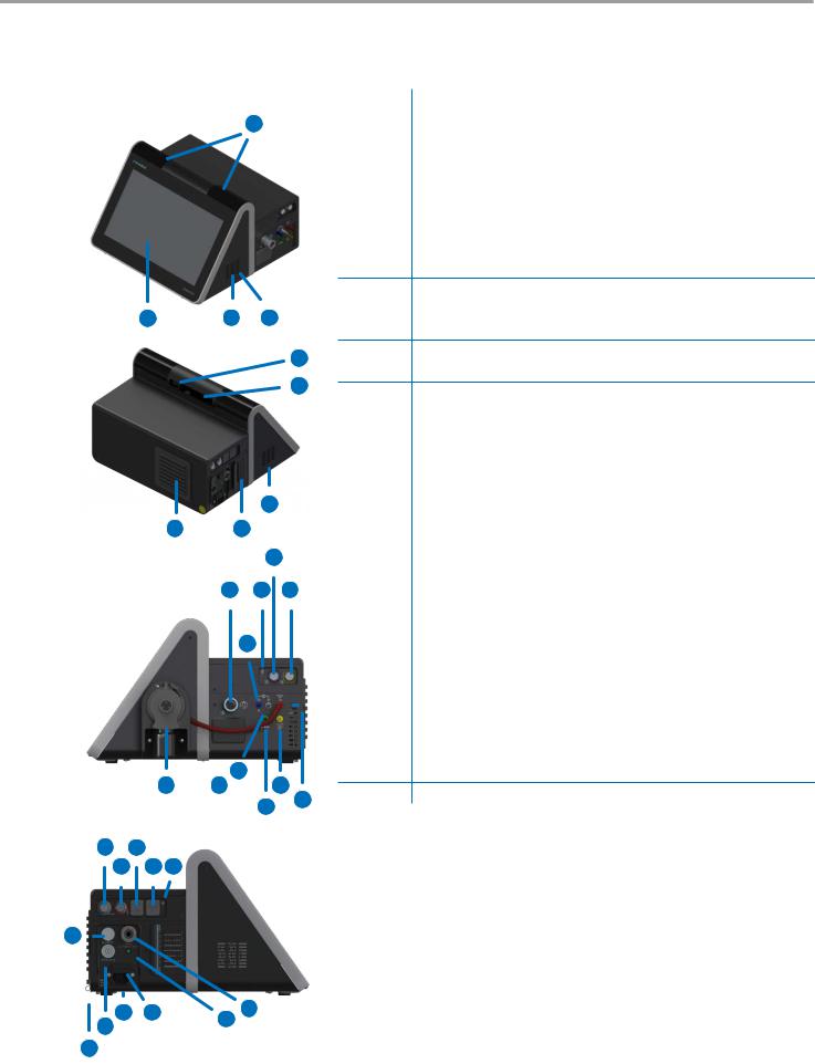
3.2Overview of bellavista neo
1
3
2 |
4 |
3 |
30
5
3
6 7
9
12 8 10
14
15
11 |
13 |
17 |
18 16
19 21
20 22 8
23
28 |
29 |
25 |
|
27 |
|||
26 |
|
||
|
|
24
No. |
Description |
|
|
1 |
Alarm lights |
|
|
2 |
Screen with touch-screen function |
|
|
3 |
Speaker |
|
|
4 |
Attachment of expiratory valve or dual limb adapter |
|
|
5 |
Handle |
|
|
6 |
Cover for cooling air filter |
|
|
7 |
Cover for patient air filter |
|
|
8 |
Connection Assist button |
9External device interface (blue)
•Connector for SpO2 sensor
•Data Communication Interface
10External device interface (yellow)
•Connector for CO2 sensor
11 |
Expiratory valve or, alternatively, dual limb adapter |
|
|
12 |
Inspiration patient connector |
|
|
13 |
Cover for O2 sensor |
|
|
14 |
Connector for bedside pressure measurement |
|
|
15 |
Connector for flow sensor |
|
|
16 |
Connector for expiratory valve |
|
|
17 |
Nebuliser pressure connector |
|
|
18 |
PAux additional pressure measurement connector |
|
|
19 |
bellavista bus |
|
|
20 |
Nurse call |
|
|
21 |
2 × USB 2.0 * |
|
|
22 |
100 Mbit Ethernet |
|
|
23 |
On/Off |
|
|
24 |
Power cord set strain relief |
|
|
25 |
Oxygen connector |
|
|
26 |
External 24 VDC power supply |
|
|
27 |
Power indicator (green LED = battery charging) |
|
|
28 |
Power plug |
|
|
29 |
Device fuse 2 × T 6.3 AH, 250 V |
30Display Port (for servicing purposes)
*It is recommended not to plug in or unplug any USB devices when ventilation is taking place.
18 |
imtmedical ag |

Description of the device
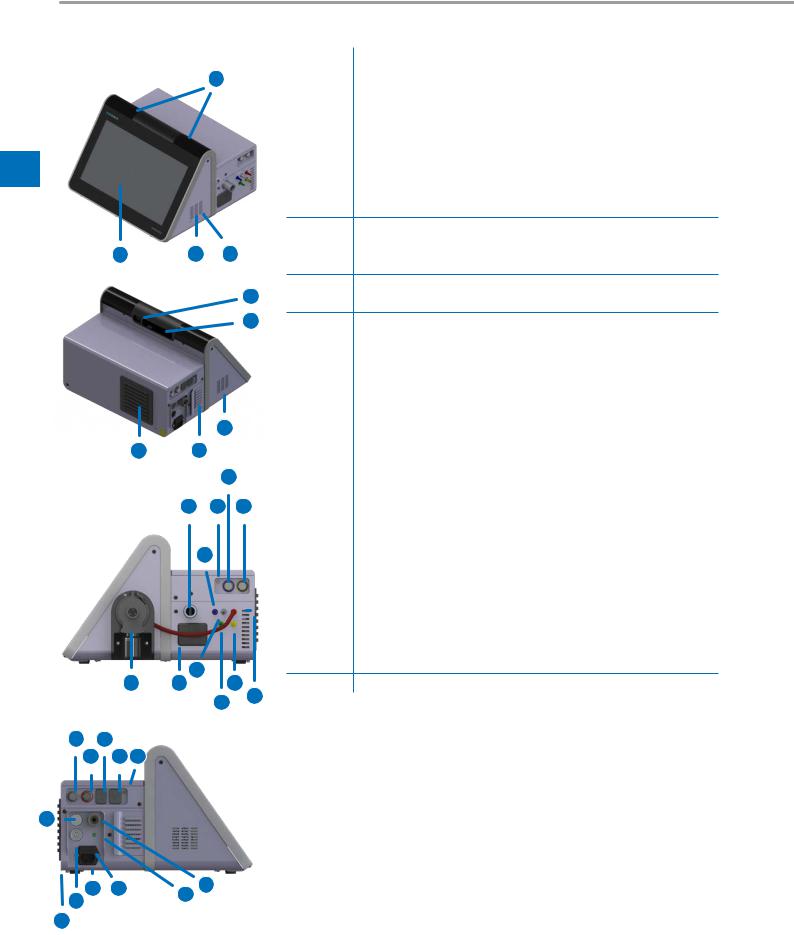
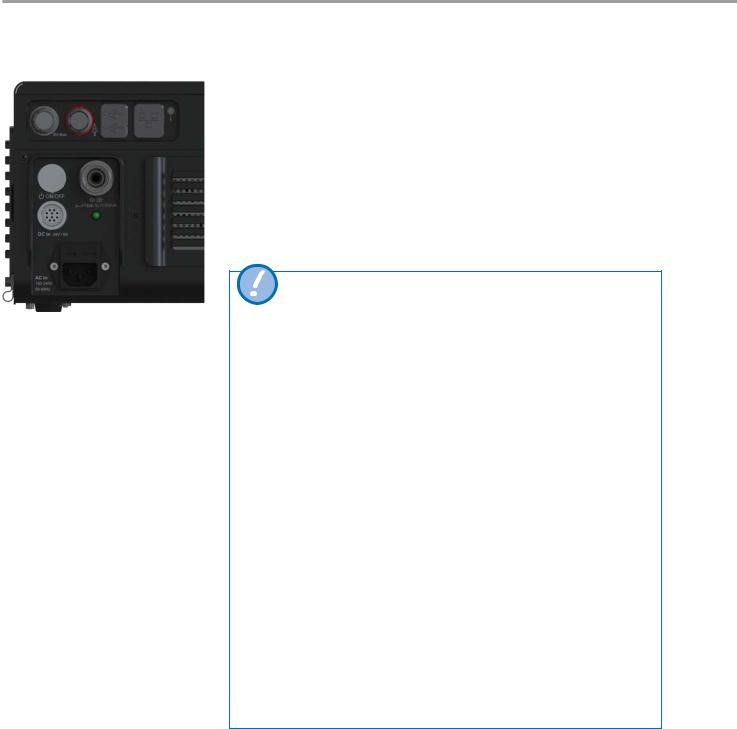
3.3Overview of bellavista 1000 e
1
3
2
4
30
29
3
6
5
8
11 7 9
13
10 |
12 |
14 |
|
16 |
|
|
17 |
15 |
|
|
|
|
||
|
|
|
|
18 20
19 21 7
22
27 |
28 |
24 |
|
25 |
26 |
||
|
23
imtmedical ag
No. Description
1Alarm lights
2Screen with touch-screen function
3Speaker
4Display Port (for servicing purposes)
5Cover for cooling air filter
6 |
Cover for patient air filter |
3 |
7Connection Assist button
8External device interface (blue)
•Connector for SpO2 sensor
9External device interface (yellow)
•Connector for CO2 sensor (optional)
10 |
Expiratory valve |
|
|
11 |
Inspiration patient connector |
|
|
12 |
Cover for O2 sensor |
|
|
13 |
Connector for bedside pressure measurement |
|
|
14 |
Connector for flow sensor |
|
|
15 |
Connector for expiratory valve |
|
|
16 |
Nebuliser pressure connector |
|
|
17 |
PAux additional pressure measurement connector |
|
|
18 |
bellavista bus |
|
|
19 |
Nurse call |
|
|
20 |
2 × USB 2.0 * |
|
|
21 |
100 Mbit Ethernet network |
|
|
22 |
On/Off |
|
|
23 |
Power cord set strain relief |
|
|
24 |
Oxygen connector |
|
|
25 |
External 24 VDC power supply |
|
|
26 |
Power indicator (green LED = battery charging) |
|
|
27 |
Power plug |
|
|
28 |
Device fuse 2 × T 6.3 AH, 250 V |
|
|
29 |
Data communication interface |
30Handle
*It is recommended not to plug in or unplug any USB devices when ventilation is taking place.
19
Description of the device
3.4System overview
3
3.5Air and oxygen supply
You will find the block diagram in the section “Specifications” under “Pneumatic block diagram”.
bellavista is an electronically controlled pneumatic ventilation system. It is powered by AC or DC and also provided with an internal battery set. The bellavista pneumatic system guarantees the supply of respiratory gas whilst the electrical systems control the pneumatics, monitor the alarms and provide the power supply.
The user can enter values or parameters in the bellavista microprocessor system via the touch screen. These inputs entail instructions for bellavista’s pneumatic system to ventilate the patient with a precisely controlled gas mixture. bellavista gathers readings from the proximal flow sensor and other sensors within the ventilator. Patient monitoring data can be displayed on the graphical user interface.
bellavista has two microprocessor systems, one to control the ventilation and one to control the user interface. The two processor systems cross-check each other and are able to trigger alarms independently of one another. This multiple check helps to prevent simultaneous failure of the main functions.
A comprehensive system of visual and audible alarms helps ensure the patient’s safety. Clinical alarms indicate abnormal physiological conditions. Technical alarms triggered by the ventilator’s self-tests, including ongoing background checks, can indicate hardware or software failures.
bellavista has several ways of ensuring a safe ventilation pressure. Maximum working pressures are ensured by appropriate alarm limits. If the set upper pressure alarm limit is reached, the expiratory valve opens.
bellavista uses ambient air and high-pressure oxygen. Ambient air is drawn in through the fresh air inlet and compressed by a turbine. Oxygen is supplied through a pressure port. An electronic blender mixes the oxygen and air to achieve the concentration entered by the user.
The gas is delivered to the patient through a microprocessor-controlled inspiratory valve. bellavista ventilates the patient through the inspiratory limb of the breathing circuit, which may include an inspiratory filter, flexible tubes, the humidifier system, a water trap, the Y-piece, the flow sensor and other components.
Gas exhaled by the patient is discharged through the flow sensor and the optional expiratory limb of the breathing circuit. Measurements taken by the flow sensor are used to determine the pressure, flow and volume.
An oxygen sensor monitors the oxygen concentration of the gas delivered to the patient.
20 |
imtmedical ag |

Preparing for ventilation
4 Preparing for ventilation
4.1Checking delivery
4.2First steps
bellavista ventilator, completely packaged, with accessories, comprising:
•Ventilator
•Power plug set
•Document box
•Accessory bag
•Bacterial filter
• |
Breathing circuit |
4 |
|
• |
EasyLung test lung |
||
|
• Set of filter mats (patient air filter and device filter)
Step Description
1Connecting the breathing circuit
2Switching on bellavista
3On the start screen
•Configure breathing circuit
•Enter patient type
•Specify start parameters for ventilation
•Start ventilation
You will find more options in the |
|
During ventilation: |
|
|
|
|
|
section “Operation”. |
|
|
|
|
|
|
Cockpit for ventilation and settings |
|
|
|
|
|
|
|
|
|
|
|
Select and set ventilation mode |
|
|
|
|
|
|
|
Monitoring |
|
|
|
|
|
|
|
Alarms |
|
|
|
|
|
|
|
Shutdown |
|
|
|
|
imtmedical ag |
21 |
Preparing for ventilation
4.3 |
Connecting supply lines |
Connect the power plug set to bellavista and an appropriate mains socket. bellavis- |
|
|
ta can be operated at 100 to 240 VAC and from 50 to 60 Hz and automatically adjusts |
|
|
to the respective voltage and frequency without the need for a manual switchover. |
• Connect the oxygen supply, if available.
• Connect the nurse call, if available, to the connector.
• Always perform the quick check.
|
|
Secure the power plug set with a strain relief to prevent it from being acciden- |
|
||
4 |
|
tally unplugged. Only pull on the plug, not the cable. |
|
|
|
|
|
|
Keep the power plug set away from the patient to avoid strangula-
tion.
Power cable connection
The absence of a ventilation alternative such as a self-priming, user-operated resuscitator with a breathing mask (ventilation bag as specified in ISO 10651-4) can lead to the patient's death if the ventilator fails.
Only use earthed cables in order to avoid the risk of an electric shock.
Do not use:
•a power plug set longer than 3 m
•a defective power plug set
•a power plug set that is not earthed
•extension cables
•double plugs or adapters
If there are concerns about the condition or set-up of the earth wire, bellavista may only be operated in battery mode.
Earthing is only reliable if the device is plugged into a socket marked as being suitable for medical equipment.
22 |
imtmedical ag |

Preparing for ventilation
4.4Battery operation
Display the battery indicator by clicking on the top of the screen. The white dot on the right prevents the display from disappearing after a short period.
bellavista 1000 can be operated in battery mode for at least 4 hours. The ventilation settings will have a significant impact on battery life. Battery operation is monitored by several alarms.
Battery indicator
…% |
Battery is charging or fully charged |
calc |
Calculation of new battery time |
…h…min |
Battery time remaining |
4
Optimise battery time:
•Always charge the batteries fully before running bellavista from the battery or if bellavista has not been used for any lengthy period.
•Battery monitoring is fully automated. Keeping bellavista connected to the mains all the time has no negative effect on battery time.
•Minimum charge: the optimum state of charge during lengthy periods of non-use is 40%. Charge for 4 hours every 6 months. The battery will also charge when bellavista is not switched on.
Lengthen the life of the battery:
•Avoid battery depletion
•Avoid high temperatures (whether in operation or in storage).
Never leave the patient unattended during battery operation! Keep an alternative ventilation option always on hand.
Continuously monitor the remaining battery life, especially when settings have been changed! Do not continue operating bellavista until the battery is completely dead. Connect to the mains power supply in good time!
After a storage period of ≥ 6 months connect bellavista to the power supply for at least 4 hours in order to charge the batteries.
4.4.1 |
Alarms |
|
Event |
|
Alarm |
|
||
|
|
|
Interruption of the |
Message, after two minutes an alarm that disappears as soon as: |
|
power supply |
• the user confirms the message. |
|
|
|
• the power supply has been restored. |
|
|
|
Remaining battery |
Message, after two minutes an alarm that disappears as soon as: |
|
life <1 h |
|
• the user confirms the message. |
|
|
• the power supply has been restored |
|
|
|
Remaining battery |
Continuous high priority alarm. Maximum 10 min battery life |
|
life <15 min |
guaranteed at the time of occurrence of the event. |
|
|
|
|
Remaining battery |
Ventilation is stopped. Continuous high priority alarming with |
|
life 0 min |
|
additional buzzer alarm sound until the battery is completely |
|
|
drained. |
|
|
|
imtmedical ag |
23 |
Preparing for ventilation
4.5Oxygen connector
4
1 2
Oxygen connection adapter
Oxygen can be fed through the oxygen supply connector, irrespective of the ventilation mode.
|
Adapter type |
Pressure |
Flow |
|
|
|
|
1 |
DISS 301.259.000 |
0 –7 bar |
0 –110 L/min |
|
|
|
|
2 |
NIST 301.258.000 |
0 –7 bar |
0 –110 L/min |
|
|
|
|
If there is any uncertainty regarding the quality of the oxygen supply, use the optional O2 filter and water trap.
Do not connect nitrogen oxide, helium, heliox or other gases.
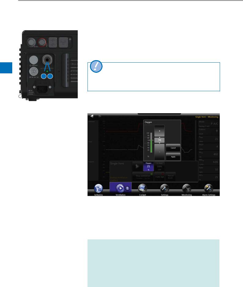
4.5.1O2 functions
The O2 blender allows accurate oxygen dosage
•FiO2 concentration 21 – 100%
•Oxygen suction
•An alarm sounds if the desired concentration is not reached (e.g. in case of low pressure supply)
•FiO2 monitoring and alarms
The battery status bar at the top of the screen displays the symbol “O2” as soon as oxygen is connected.
For configuration of O2 supply <1.5 bar or O2 supply <100 % O2 see Configuration Assist.
If there is an oxygen sensor failure, the oxygen options can be temporarily disabled in Configuration Assist
24 |
imtmedical ag |
Preparing for ventilation
4.5.2Oxygen consumption
Patient/Mode |
Formula for estimating O2 consumption |
|
|||
|
|
|
|
||
Adult, paediatric |
(FiO2 - 21%) / 79% × (MVInsp + (base flow × 2/3)) and nebuliser |
|
|||
|
Assumptions: I:E = 1:2, PEEP > 2 |
|
|||
|
Applicable to all modes apart from 1 |
|
|
||
Neonatal, CPAP, |
(FiO2 - 21%) / 79% × (MVInsp + (base flow × 2/3)) and nebuliser |
|
|||
beLevel, APRV 1 |
Assumption: PEEP > 2 |
|
|||
Base flow |
Adult |
6 L/min |
|
|
|
|
Paediatric |
15 L/min |
4 |
||
|
If PEEP < 2 mbar, base flow is reduced to a minimum of 5 L/min |
||||
|
|
|
|
||
Nebuliser |
8 L/min with active nebuliser (insp, exp, cont) |
|
|||
|
|
|
|
|
|
If the oxygen option is switched off, always use external O2 measurement.
Only use medical oxygen. To avoid inadequate or excessive supply of oxygen, use the bellavista oxygen monitoring system and its alarm options.
Possible complications:
The use of oxygen can lead to serious complications. The impact on the processes of peripheral and cerebral respiratory control can cause respiratory pauses.
Lung tissue can be damaged by the toxic effect of high concentrations.
Use clean, intact oxygen tubing.
Only after the oxygen cylinder has been connected should the flow valve of the oxygen supply be slowly opened.
An oxygen leak in the O2 supply or in bellavista can lead to a fire risk or an inadequate supply of oxygen to the patient. Check the system regularly for leaks. In the event of a leak, turn off the oxygen source immediately.
Use oxygen only in well ventilated rooms.
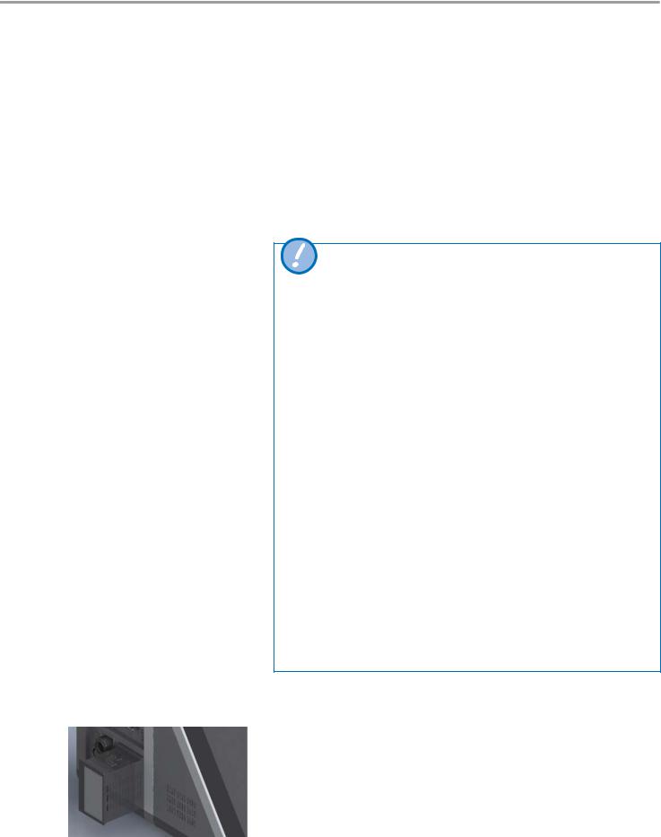
4.6 |
Inlet filter |
An optional filter protects the patient air inlet of bellavista against external contamina- |
|
|
tion. It is fitted instead of the standard inlet filter. Two different filter types are available. |
|
|
See also the relevant set of instructions 302.505.000 |
• 302.303.000 Inlet filter HEPA H14
imtmedical ag |
25 |
Preparing for ventilation
4.7 |
Switching on bellavista |
Switch on bellavista with the “ON/OFF” button on the left-hand side of the device. |
|
|
Start-up takes ≈1 min. |
During the start-up procedure bellavista undergoes an automatic self-test. If there are any deviations an alarm will sound and if necessary the device will be deactivated.
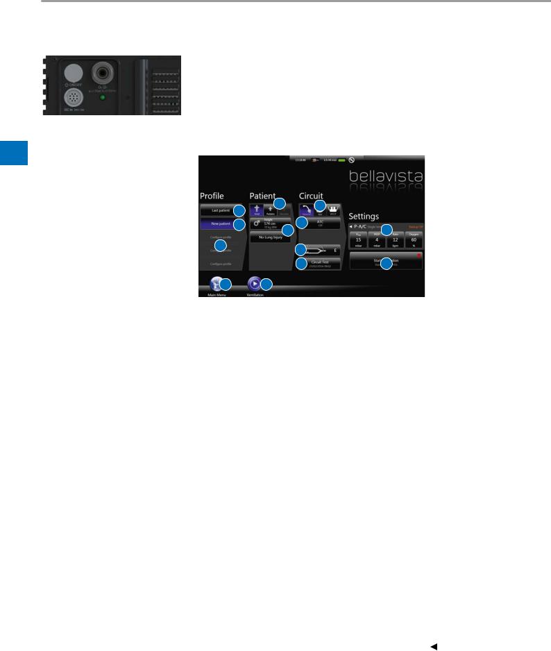
4.8 |
Start screen |
On the start screen the following settings can be made: |
4
1a |
2 |
4a |
|
||
|
|
|
1b |
4b |
5 |
|
3 |
|
1c |
4c |
|
|
|
|
|
4d |
6 |
7 |
6 |
|
Objective |
|
Steps |
|
|
|
To continue ventilation |
|
• Change ventilation setting if necessary (5) |
with the same settings |
|
• Start ventilation (6) |
|
|
|
In an emergency |
|
• Load predefined profile (1c) |
|
|
• Start ventilation (6) |
|
|
|
To set a new patient |
|
• Select new patient (1b) or profile (1c) |
|
|
• Set patient type (2), with additional information (3) if nec- |
|
|
essary |
|
|
• Set and check breathing circuit (4) |
|
|
• Adjust ventilation settings (5) |
|
|
• Start ventilation (6) |
Selection |
|
Description |
|
||
|
|
|
1 |
|
Select basic settings/profile |
|
|
|
1a |
|
Continue ventilation with the same settings as previously. |
|
|
|
1b |
|
Configure ventilation for a new patient, based on the current |
|
|
settings. |
|
|
|
1c |
|
Load predefined profile (see also Data Assist). |
|
|
|
2 |
|
Select patient type, Adult / Paediatric / Neonatal. |
|
|
|
3 |
|
Set gender, height and lung condition as optional to obtain |
|
|
start settings for ventilation and alarms. |
|
|
|
4 |
|
Select breathing circuit. |
|
|
|
4a |
|
Set invasive, non-invasive ventilation or HFOT (High Flow |
|
|
Oxygen Therapy). |
|
|
|
4b |
|
ATC Automatic Tube Compensation |
|
|
(disabled in Configuration Assist) |
|
|
|
4c |
|
Breathing circuit (1- / 2-tube, expiratory valve, flow sensor) |
|
|
|
4 d |
|
Perform breathing circuit test. |
|
|
|
5 |
|
Ventilation adjustment parameters (See all: ) |
|
|
|
6 |
|
Start ventilation. |
|
|
|
7 |
|
Access to the main menu without starting ventilation. |
|
|
|
26 |
imtmedical ag |
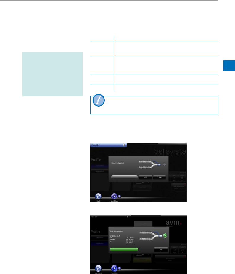
When a circuit test is successfully executed the circuit test button indicates dates and time in the start screen and ventilation menu. Not executed or aborted circuit tests will also be shown as “not performed” with a yellow background.
Preparing for ventilation
4.8.1Breathing circuit test
The system test performs the following measurements and checks (for limits see section “Specifications” under “Breathing circuits and flow sensor”):
Step |
Action, measurement, check |
1Interrupt patient / test lung
•Insp. flow resistance of breathing circuit
•Flow sensor calibration
2Close the breathing circuit
•Breathing circuit leakage
• |
Exp. flow resistance of breathing circuit |
4 |
• |
Compliance of breathing circuit |
|
3Calibration of proximal flow sensor in expiration direction (only with Adult/ Paediatric flow sensor)
4Calibration of proximal flow sensor in inspiration direction
This step is of major importance because the proper functioning of sensors, valves and alarms depends on it.
4.8.2Quick check on start-up
Perform the quick check each time the device is started.
Breathing circuit test
Circuit test successful/ventilation overlay
imtmedical ag |
27 |

Preparing for ventilation
4.9Selecting the breathing circuit
4 |
4.10 Selecting the patient type |
|
bellavista supports a very wide range of different breathing systems for various applications and preferences.
•Passive 1-tube circuit for non-invasive ventilation
•Active 1-tube circuit for invasive and non-invasive ventilation
•Dual limb circuit for invasive and non-invasive ventilation
•Neonatal breathing circuits and patient interfaces for nCPAP and nIPPV
•Breathing circuits and patient interfaces for HFOT (High Flow Oxygen Therapy)
Patient type |
Adult |
Paediatric |
Neonatal (optional) 1 |
Height |
> 145 – 250 cm |
50 – 171 cm |
n. a. |
|
|
|
|
IBW (Ideal Body Weight) |
> 39 – 138 kg |
6 – 63 kg |
<10 kg |
|
|
|
|
Tidal volume Vt |
250 – 2500 mL |
40 – 500 mL |
2 – 250 mL |
|
|
|
|
Tube (for invasive ven- |
> 5 mm |
3 – 7 mm |
< 5 mm |
tilation) |
|
|
|
|
|
|
|
Tube diameter |
22 mm |
15 – 22 mm |
10 – 12 mm |
|
|
|
|
Flow sensor |
301.328.010 |
301.328.010 |
301.470.010 |
|
|
|
|
1 Not available in the USA
4.11Safety instructions about breathing circuits
Avoid occlusion of the expiratory valve.
Omitting a bacterial filter or using an incorrect bacterial filter can bring about transmission of pathogens to the patient and contamination
of bellavista. Change the bacterial filter according to the manufacturer’s instructions and before each new patient. Used filters must be disposed of as medical waste.
To avoid electric shocks to the patient and/or user, refrain from using antistatic or electrically conductive breathing circuits or lines. Additional accessories in the breathing circuit can significantly increase the flow resistance and, as a result, negatively impact ventilation performance.
Comply with the instructions provided by the manufacturer of the humidifier in order to prevent exposure of the patient to a hazard and damage to bellavista. Place the humidifier at a lower level than bellavista and the patient in order to prevent aspiration of water and flooding of bellavista.
Calibrate flow sensor in the event of
•a new patient
•a new flow sensor
•“Calibrate flow sensor” alarm
In the case of non-invasive ventilation, the expiratory measurements of volumes and capnography values can differ considerably from the actual expiration on account of leakage.
28 |
imtmedical ag |
Preparing for ventilation
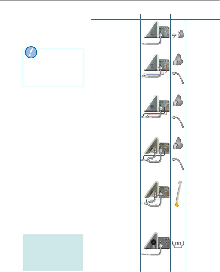
4.12Connecting thebreathing circuit
Breathing circuit C
Not to be used for life-sustaining ventilation owing to the absence of expiratory volume monitoring.
Various breathing circuits: see separate list of validated accessories. Configure breathing circuit using the start screen. When inserting or removing the tubes, grip by the sleeve.
Breathing circuit |
Connection |
Patient interface |
4.12.1 |
Breathing circuit A |
Non-invasive NIV |
|
|
|
|
Ventilated mask with |
|
|
1-tube circuit, passive, Adult/ |
leak and safety valve |
|
||
Paediatric |
|
|
|
|
Prox. pressure measurement |
|
|
|
|
Expiratory flow calculated |
|
|
|
|
|
|
|
|
|
4.12.2 |
Breathing circuit C |
Non-invasive NIV |
|
|
Non-ventilated mask |
|
|||
1-tube circuit, Adult/Paediatric |
without leak (ventilat- |
|
||
ed mask can be used |
4 |
|||
Proximal pressure measure- |
as an alternative) |
|
||
ment |
|
Invasive |
|
|
Expiratory flow calculated |
|
|||
Tube without leak, |
|
|||
|
|
|
||
|
|
tracheotomy cannula |
|
|
|
|
|
|
|
4.12.3 |
Breathing circuit D |
Non-invasive NIV |
|
|
Non-ventilated mask |
|
|||
|
|
|
||
1-tube circuit, Adult/Paediatric |
without leak (ventilat- |
|
||
ed mask can be used |
|
|||
Proximal pressure measure- |
|
|||
as an alternative) |
|
|||
ment |
|
|
||
|
|
|
|
|
Expiratory flow calculated |
|
|
|
|
|
|
|
|
|
|
|
Invasive |
|
|
|
|
Tube without leak, |
|
|
|
|
tracheotomy cannula |
|
|
|
|
|
|
|
|
|
Non-invasive NIV |
|
|
4.12.4 |
Breathing circuit E |
Non-ventilated mask |
|
|
|
|
without leak (ventilat- |
|
|
Dual limb circuit, Adult/Paediat- |
ed mask can be used |
|
||
ric/Neonatal |
as an alternative) |
|
||
Proximal pressure measure- |
|
|
|
|
ment |
|
|
|
|
|
Invasive |
|
||
Expiratory flow calculated |
|
|||
Tube without leak, |
|
|||
|
|
|
||
|
|
tracheotomy cannula |
|
|
|
|
|
|
|
4.12.5 |
Breathing circuit E |
Non-invasive NIV |
|
|
(Neonatal) |
|
|||
|
neo NIV |
List of compatible |
|
|
|
|
nasal interfaces |
|
|
Dual limb circuit, Neonatal, for |
(masks and prongs) |
|
||
ventilation modes nCPAP and |
|
|
|
|
nIPPV |
|
|
|
|
Proximal pressure measure- |
|
|
|
|
ment |
|
|
|
|
Expiratory flow calculated |
|
|
|
|
|
|
|
|
|
|
|
List of compatible |
|
|
4.12.6 |
Breathing circuit |
interfaces (nasal |
|
|
|
for HFOT |
cannulas) |
|
|
|
|
|
|
|
1-tube circuit, for HFOT (High Flow Oxygen Therapy)
Proximal pressure measurement
Expiratory flow calculated
No breathing circuit test required!
imtmedical ag |
29 |
Loading...