


NMTC module
Table of contents
 Loading...
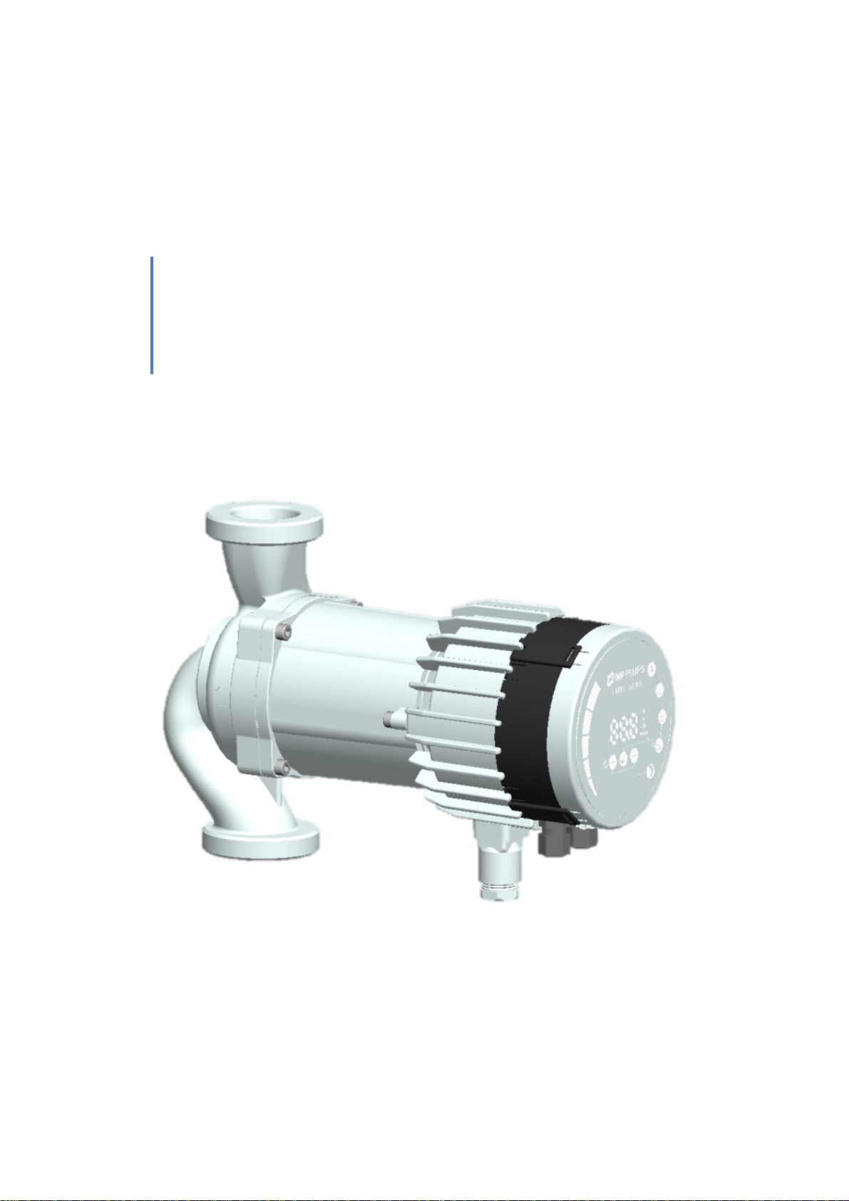
NMTC module
Functional profile and user manual
preliminary, 7340055, v4

2

3
Contents
1 Symbols and conventions used in this
document ........................................................4
1.1 Abbreviations and conventions .........4
2 Introduction.............................................5
2.1 System diagram ................................5
2.2 Specifications ...................................5
3 Module layout .........................................7
3.1 Connection considerations ...............8
3.2 Connecting the module wiring ..........9
3.3 Connection examples ..................... 11
4 Control modes and priorities ................. 12
4.1 Priority of settings .......................... 12
4.2 Control variables............................. 13
4.3 Module mode selection .................. 13
4.4 Mode 1 ........................................... 14
4.4.1 Digital (switch) control ............ 15
4.4.2 Analog control ........................ 17
4.5 Mode 2 ........................................... 18
5 Relay output .......................................... 20
6 Ethernet................................................. 21
6.1 Bus topology ...................................21
6.2 Connecting to pump ad-hoc with a
cross over cable .........................................22
6.3 Connecting to pump via router .......26
6.4 Pump configuration over Ethernet ..27
7 Modbus .................................................31
7.1 Modbus related interface ...............31
7.2 Bus topology ...................................31
7.3 Connection to Modbus ...................32
7.4 Speed, parity and address ...............32
7.5 Termination ....................................32
7.6 Register block overview ..................33
7.7 NMTC Configuration register block .33
7.8 NMTC Status register block .............34
7.9 Pump control register block ............34
7.10 Pump status register block ..............36
7.11 Pump data register block ................38
7.12 Modbus telegrams and function
codes 39
8 Fault finding ...........................................39
8.1 Error codes .....................................39
8.2 Communication faults .....................41
WARNING!
Prior to installation and commissioning, read these instructions first. Installation and operation must
comply with local regulations.
WARNING!
Installation and use of this product requires experience and knowledge of this or similar products.
Persons with reduced physical, mental or sensory capabilities must not use this product, unless
properly instructed and supervised. Children must not be allowed to play with this product.

4
1 Symbols and conventions used in this document
WARNING!
Denotes that a failure to observe those instructions might cause damage to equipment or pose danger
to the user.
NOTE: - Gives additional tips or instructions that might ease the job and ensure proper operation.
1.1 Abbreviations and conventions
Abbreviation
Description
Baud, Baud rate
Serial communication speed, in bits per second including start, parity and stop bits.
CRC
Cyclic Redundancy Check, additional bytes used to confirm valid data transmission.
Ethernet
IEEE 802.3, mostly referring to 10BASE-T RJ-45 connector present on board.
H
Differential pressure, often called Head.
LED
Light Emitting Diode.
Modbus
A serial communication protocol used for device automation and remote access.
NMTC
NMT pump Communication module.
Q
Pump flow or flow rate.
RTU
Remote Terminal Unit.
RS-485
Multi drop serial network wiring, used to transfer Modbus data.
For Modbus use, this manual assumes that the reader is familiar with commissioning and configuring of
Modbus devices. It is also assumed that an existing Modbus RTU network on RS-485 wiring with
Modbus master is present.
For Ethernet and web interface use, this manual assumes that the reader knows how to configure or
already has preconfigured Ethernet network.
For use of analog signals and relay output signals, external controller needs to be configured and used.
Proper operating mode must also be selected for the module.
NOTE:
• Data in this document are subject to change.
• Actual implementation might differ by pump model and software revision.
• Make sure you are using the right manual for your product.
• Verify proper operation in the final system.
• Manufacturer cannot be held responsible for problems caused either directly or indirectly by
the use of information in this manual.
5
2 Introduction
This manual describes the NMTC module for NMT range of pumps that is either integrated or separately
available. This module is used for various remote control applications, including:
• Remote on/off
• Analog 0..10V voltage control
• Modbus remote control
• Status relay feedback
• Web access over Ethernet
It is suitable for medium size NMT pumps, 90-440W of rated power.
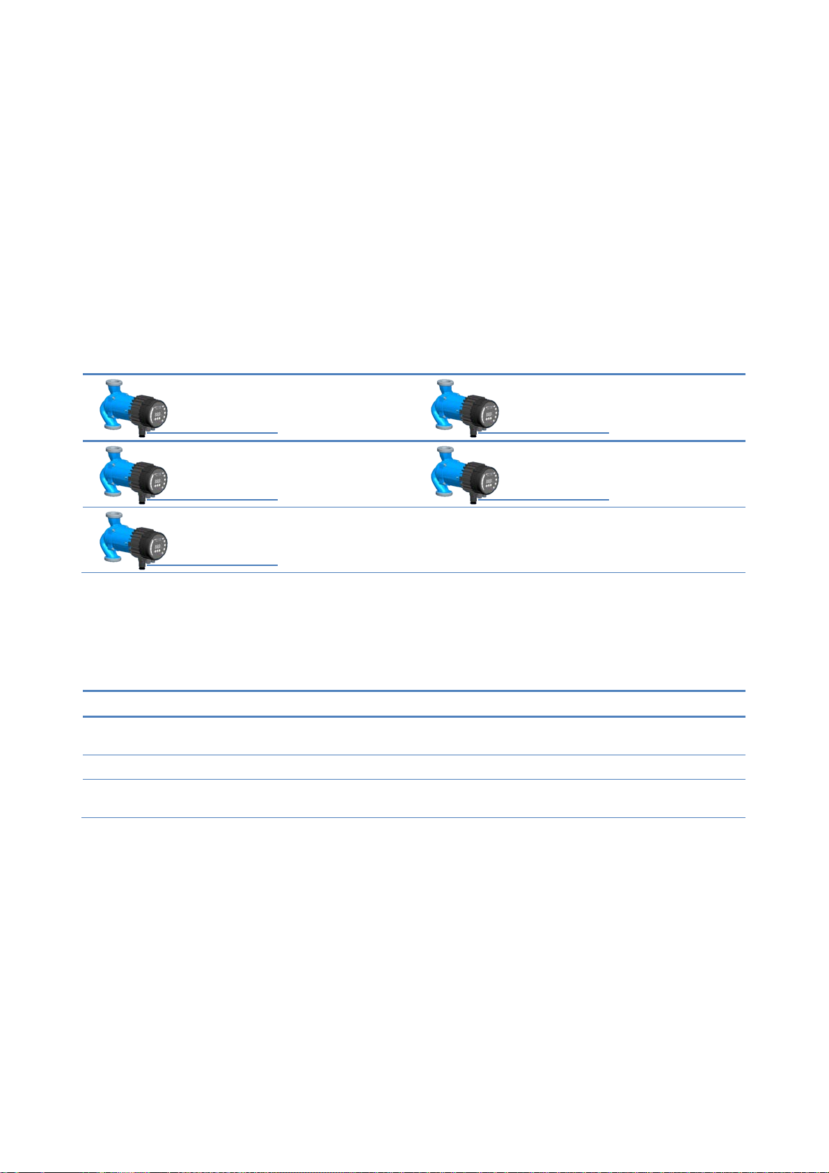
2.1 System diagram
There are several possible connection configurations. Not all functions can be used simultaneously.
…
2.2 Specifications
The table below is an overview of NMTC specifications. For details, please refer to appropriate
sections of this manual.
General data
Ambient humidity
<95 % relative, non-
condensing
Also see appropriate pump data for other
ambient specifications.
Dimensions
[∅
x H]
112 mm x 32 (45) mm Dimensions without glands.
Power supply and
connection
5V@500mA supplied
by the pump
6-pin connector further extended for display.
on/off + 0..10V + relay output
Modbus RTU + Relay output
Ethernet + on/off + 0..10V
Modbus RTU + Ethernet
Ethernet + on/off + relay output

6
Modbus specifications
Data protocol Modbus RTU
Modbus connector Screwless terminals
2+1 pins. See section 7.3 “
Connection to
Modbus
”.
Modbus connection
type
RS-485
Modbus wire
configuration
Two-wire + common
Conductors: A, B and COM (Common).
See section 7.3 “
Connection to Modbus
”.
Communication
transceiver
Integrated, 1/8 of
standard load
Connect either via passive taps or daisy chain.
Maximum cable
length
1200 m See section 7.5 “
Termination
”.
Slave address 1-247
Default is 245, settable over Modbus. See
section 7.4 “
Speed, parity and address
”.
Line termination Not present
Line termination is not integrated. For low
speed/short distance, termination can be
omitted. Otherwise, terminate the line
externally on both ends.
Supported
transmission speeds
1200, 2400, 4800,
9600, 19200, 38400
baud
Settable over Modbus register [default=19200].
Start bit 1 Fixed.
Data bits 8 Fixed.
Stop bits 1 or 2
1 stop bit minimum, up to 2 when parity not
enabled [default=1]
Parity bit Even/odd/none [default=Even]
Modbus visual
diagnostics
LED2
Flashing yellow when data reception detected.
Combined (OR) with Ethernet ACT function.
Maximum number of
Modbus devices
247
Limited by possible Modbus addresses to 247.
1/8 nominal load enables 256 devices.
Maximum Modbus
packet size
256 bytes Including address (1) and CRC (2) bytes.
Isolation
Common ground
(COM) with SET1,
SET2 and SET3.
Modbus shares common ground with other
signals.
Ethernet specifications
Ethernet connector RJ-45 10BASE-T, 10Mbit/s connection.
Connection type and
services
-
Web server (port 80)
-
Firmware update over web interface
-
Optional Modbus RTU over TCP/IP
Default IP address 192.168.0.245 192.168.0.246 for right twin pump.
Ethernet visual
diagnostics
LED1 / LINK
Slowly blinking when module is powered,
permanently lid when link established.
LED2 / ACT
Flashing yellow when data reception detected.
Combined (OR) with Modbus data reception
indication.
7
Mode selection switch
Adjustment
10 position rotary
switch
Position read at power-on.
Used for relay configuration and module
configuration reset.
Analog signals (SET1, SET2, SET3)
Input voltage range -1..32VDC When used as input.
Output voltage
range
0..12V
When used as output. 5mA max. load allowed
per output.
Input resistance ~100k 0.5mA load is added for most configurations.
Output current sink
range
0..33mA (4-20mA) Current sink to COM if configured as output.
Relay specifications
Connection type Screwless terminals
Rating
- 230 VAC, 3 A, AC1
-
32 VDC, 3 A
Potential free changeover contact.
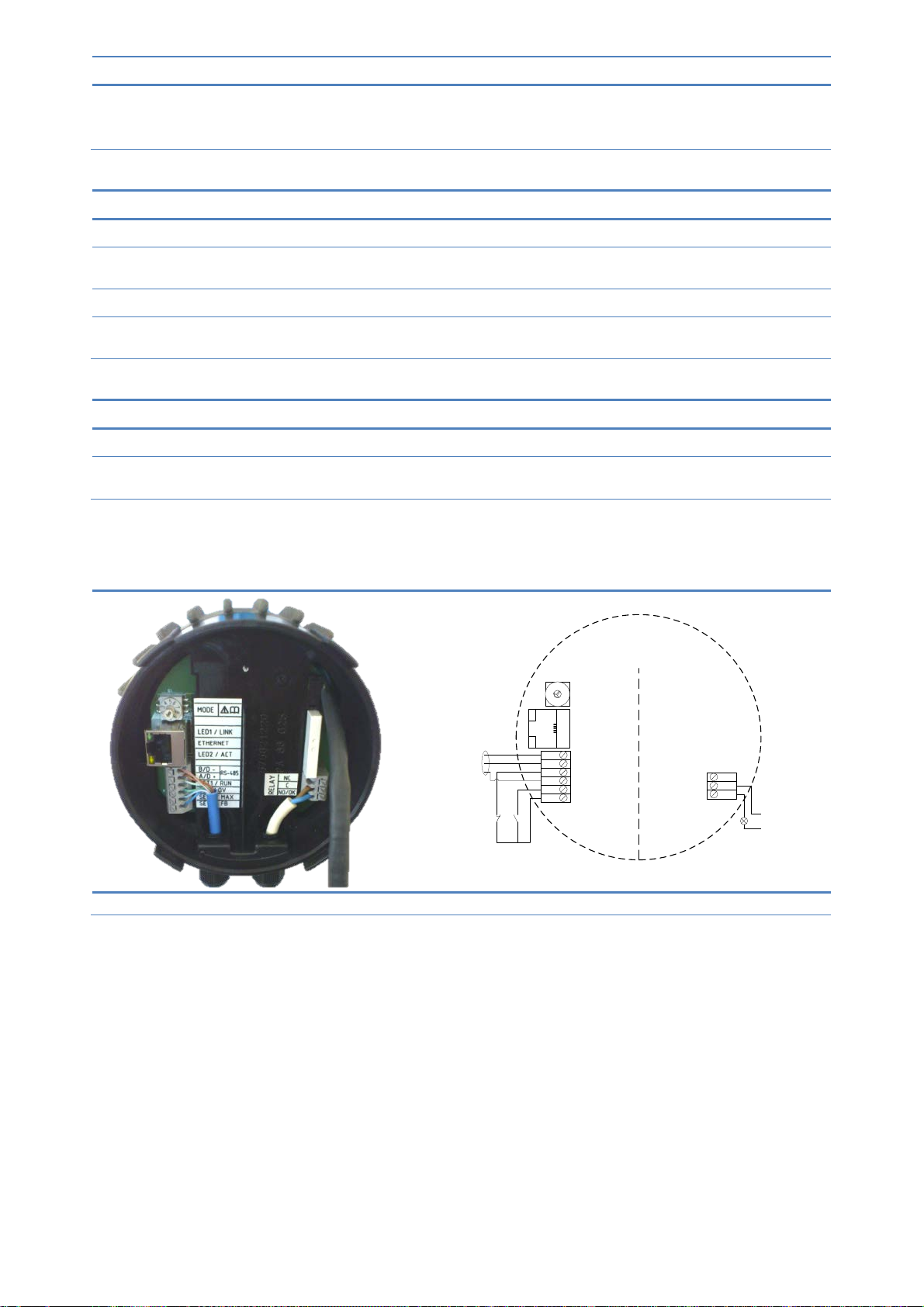
3 Module layout
Modbus signal
SET3 / FB
SET2 / MAX
COM / 0V
SET1 / RUN
A/D +
B/D -
NC
C
NO
RS-485
LED2 / ACT
LED1 / LINK
ETHERNET
MODE
2
1
3
4
5
6
7
8
9
0
MAX
RUN
ALARM
Figure 1: Typical module connection
8
Terminal
Designation
Description
MODE
Mode selection rotary switch. Used to configure mode of operation for the circuit. See
section 4.3 “Module mode selection”.
LED1 / LINK
Slowly blinking when module is powered.
Blinking fast when Modbus Error
Permanently lid when Ethernet link established.
Ethernet
10BASE-T RJ-45 connector.
LED2 / ACT
Indicates Ethernet activity or Modbus activity.
B/D-
RS-485 negative data signal for Modbus.
A/D+
RS-485 positive data signal for Modbus.
SET1 / RUN
Control signal 1.
COM / 0V
RS-485 common and analog input common (ground).
SET2 / MAX
Control signal 2.
SET3 / FB
Control signal 3.
NC
Normally closed relay contact. Opens when relay is active.
C
Relay common contact.
NO / OK
Normally open relay contact. Closes when relay is active.
3.1 Connection considerations
• All cables connected must be heat-resistant to at least +85°C.
• All cables connected must be installed in accordance with EN 60204-1.
• All wires to the communications module must be connected to the terminals or cut. No loose wiring
permitted.
• If voltages over 24VAC/DC are possible on NO, C, NC terminals:
WARNING!
• Wires should be routed so no wire crosses the center barrier.
• Relay cable (NO, C, NC) must be separated from all other wiring with reinforced
insulation. Cable outer layer must not be stripped longer than 15mm. See “Cabling
preparation” below.
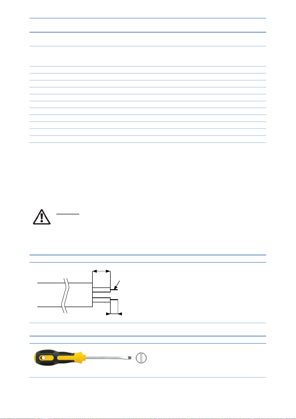
Cabling preparation
max. 15
mm
8(7-
10)mm
0.
25 - 1 mm
2
Cable for the screwless terminals should
be prepared as shown on the left.
Tools
2.4mm wide flat-bladed screwdriver is
needed to press the terminal spring
while inserting the cable.
Same tool is also used to rotate the
Mode switch.
9
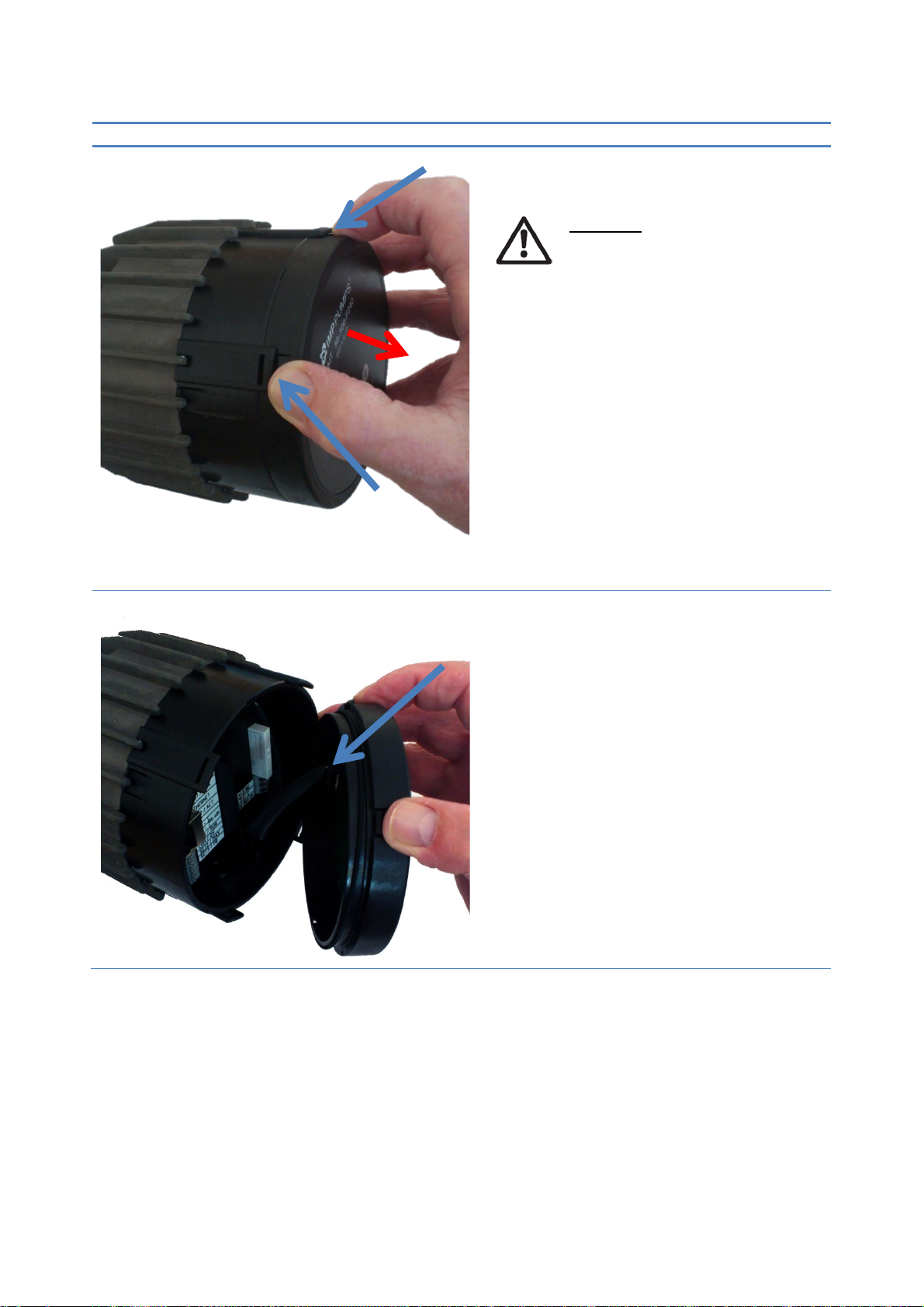
3.2 Connecting the module wiring
Opening the cover
WARNING!
Before performing any work on
the module, make sure that the
pump and module electricity
supply has been switched off and
that it cannot be accidently
switched on.
1) Press two top hooks on the display
panel. Use flat tip screwdriver if
needed.
2) Simultaneously pull display panel away
from the pump.
3) Disconnect display panel cable to ease
access to the module wiring. Wiring can
now be connected.
1.
1.
2.
3.
10
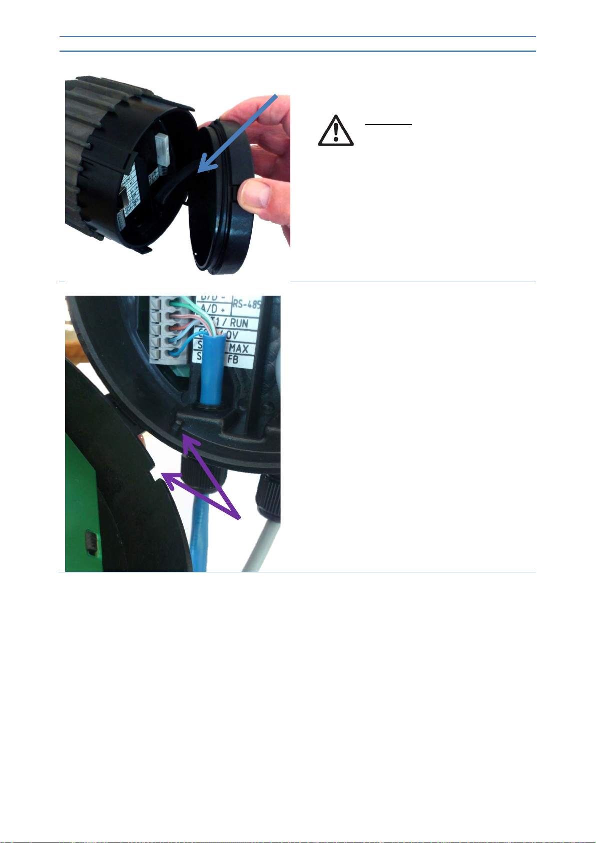
Closing the cover
WARNING!
Before performing any work on the
module, make sure that the pump
and module electricity supply has
been switched off and that it
cannot be accidently switched on.
4) Reconnect display panel cable.
5) Make sure that the position tab and
position slot are aligned.
5.
4.

11
Closing the cover
6) Make sure that the hooks are aligned.
7) Push the display back to the NMTC
module.
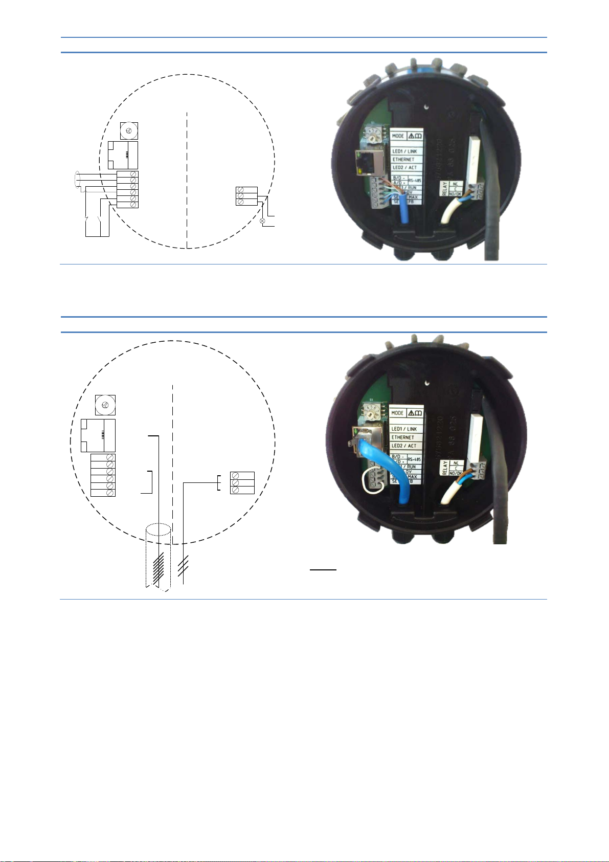
3.3 Connection examples
Default (factory) configuration
SET3/
FB
SET2 / MAX
COM / 0V
SET1 / RUN
A/D +
B/D -
NC
C
NO
RS-
485
LED2 / ACT
LED1 / LINK
ETHERNET
MODE
2
1
3
4
5
6
7
8
9
0
6.
7.
12
Relay and Modbus connection
Modbus signal
SET3 / FB
SET2 / MAX
COM / 0V
SET1 / RUN
A/D +
B/D -
NC
C
NO
RS-485
LED2 / ACT
LED1 / LINK
ETHERNET
MODE
2
1
3
4
5
6
7
8
9
0
MAXRUN
ALARM
Relay and Ethernet connection
SET3/ FB
SET2 / MAX
COM / 0V
SET1 / RUN
A
/D +
B/D -
NC
C
NO
RS
-485
LED2 / ACT
LED1
/ LINK
ETHERNET
MODE
2
1
3
4
5
6
7
8
9
0
NOTE: To maintain pump IP protection, the
network cable should be pulled through the gland
inlet and then crimped to a connector.
4 Control modes and priorities
4.1 Priority of settings
Several signals will influence the pump operation. For this reason, settings have priorities as shown in
the table below. If two or more functions are active at the same time, the one with highest priority will
take precedence.

13
Priority
Pump control panel &
Ethernet settings
External signals
1
Modbus control
1
Stop (OFF)
2
Night mode active
2
3
Max. RPM (Hi)
4
Min. curve
4
5
Stop (Run not active)
6
Max. curve
4
Stop
3
7
Setpoint setting
4
Setpoint setting
3
8
Setpoint setting
4
Examples:
• Stop on the pump display panel will stop the pump, regardless of external setpoint.
• If External Run input is inactive, the pump cannot be started over Modbus, but can be set to max
RPM on the display panel.
4.2 Control variables
Pump will respond to external controls according to selected pump operating mode. Consult proper
pump operating manual for explanation.
Symbol
Regulation mode
Module setpoint controls:
Auto mode
-
(RUN only)
Proportional pressure Maximum head
Constant pressure Maximum head
Constant speed
Speed
(RPM)
Free
5
-
(Web interface only)
Night mode
6
-
(RUN only)
4.3 Module mode selection
1
Not all inputs are available in all modes.
2
External and Modbus Stop signals become active in night mode. Due to possible confusion, use of night mode is
discouraged while using external control.
3
Only available when pump is bus controlled.
4
Not available when pump is bus controlled.
5
Multiple limits can be set. Not available on all pumps.
6
Night mode is not independent regulation mode.
A
Loading...