

Impex MWM-1800 Owner's Manual
NOTE:
Please read all instructions
carefully before using this
product
Safety Notice
Hardware Identifier
Assembly Instruction
Parts List
Resistance Chart
Warranty
Ordering Parts
MARCY HOME GYM
MWM 1800
Model
MWM 1800
Retain This
Manual for
Reference
08-28-01
OWNER'S
MANUAL
IMPEX FITNESS PRODUCTS
14777 DON JULIAN RD., CITY OF INDUSTRY, CA 91746
Tel: (800) 999-8899 Fax: (626) 961-9966
www.impex-fitness.com
info@impex-fitness.com

TABLE OF CONTENTS
BEFORE YOU BEGIN....................................................................................……….. 1
IMPORTANT SAFETY NOTICES...................................................................……….. 2
HARDWARE IDENTIFIER.....….....................................................................……….. 3
ASSEMBLY INSTRUCTIONS.........................................................................……….. 4
HOW TO USE..................................................................................................………. 21
PARTS LIST………………………………………………………………………………….. 22
RESISTANCE CHART………….......................................................................………. 23
WARRANTY.................................................................................................…………. 24
ORDERING PARTS.......................................................................................………… 24
BEFORE YOU BEGIN
Thank you for selecting the MARCY MWM 1800 HOME GYM by IMPEX
FITNESS PRODUCTS. For your safety and benefit, read this manual
carefully before using the machine. As a manufacturer, we are committed to
provide you complete customer satisfaction. If you have any questions, or
find there are missing or damaged parts, we guarantee you complete
satisfaction through direct assistance from our factory. To avoid
unnecessary delays,
Our Customer Service Agents will provide immediate assistance to you.
please call our TOO-FREE customer service number
.
Toll-Free Customer Service Number
1-800-999-8899
Mon. – Fri. 9 a.m. – 5 p.m. PST
www.impex-fitness.com
info@impex-fitness.com
1

IMPORTANT SAFETY NOTICE
PRECAUTIONS
This exercise machine is built for optimum safety. However, certain precautions apply
whenever you operate a piece of exercise equipment. Be sure to read the entire manual
before you assemble or operate your machine. In particular, note the following safety
precautions:
Keep children and pets away from the machine at all times. DO NOT
1.
leave children unattended in the same room with the machine.
2. Only one person at a time should use the machine.
3. If the user experiences dizziness, nausea, chest pain, or any other abnormal
symptoms, STOP the workout at once. CONSULT A PHYSICIAN
IMMEDIATELY.
4. Position the machine on a clear, leveled surface. DO NOT use the machine
near water or outdoors.
5. Keep hands away from all moving parts.
6. Always wear appropriate workout clothing when exercising. DO NOT wear
robes or other clothing that could become caught in the machine. Running
or aerobic shoes are also required when using the machine.
7. Use the machine only for its intended use as described in this manual. DO
NOT use attachments not recommended by the manufacturer.
8. Do not place any sharp object around the machine.
9. Disabled person should not use the machine without a qualified person or
physician in attendance.
10. Before using the machine to exercise, always do stretching exercises to
properly warm up.
11. Never operate the machine if the machine is not functioning properly.
WARNING: BEFORE BEGINNING ANY EXERCISE PROGRAM, CONSULT
YOUR PHYSICIAN. THIS IS ESPECIALLY IMPORTANT FOR INDIVIDUALS
OVER THE AGE OF 35 OR PERSONS WITH PRE-EXISTING HEALTH
PROBLEMS. READ ALL INSTRUCTIONS BEFORE USING ANY FITNESS
EQUIPMENT. IMPEX INC. ASSUMES NO RESPONSIBILITY FOR PERSONAL
INJURY OR PROPERTY DAMAGE SUSTAINED BY OR THROUGH THE USE OF
THIS PRODUCT.
SAVE THESE INSTRUCTIONS.
2

3
ASSEMBLY INSTRUCTION
Tools Required Assembling the Machine: Two Adjustable Wrenches and Allen Wrenches.
NOTE: It is strongly recommended this machine to be assembled by two or more people to
avoid possible injury.
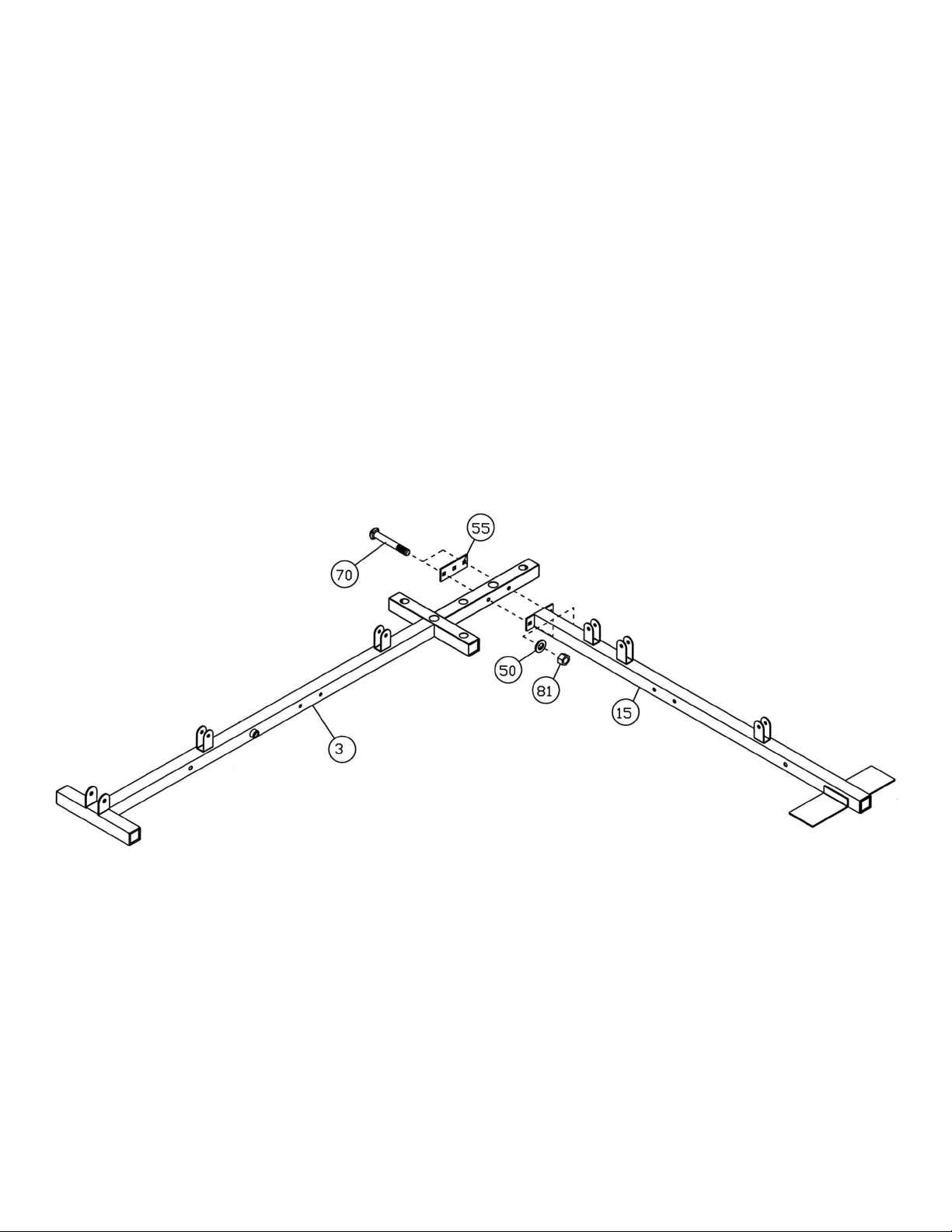
STEP 1 (See Diagram 1)
A.) Attach the Left Base Frame (#15) to the Right Base Frame (#3). Secure them with one
Bracket (#55), two M10 x 2 ¾” Carriage Bolts (#70), two ∅ ¾” Washers (#50), and two M10
Aircraft Nuts (#81).
DIAGRAM 1
4
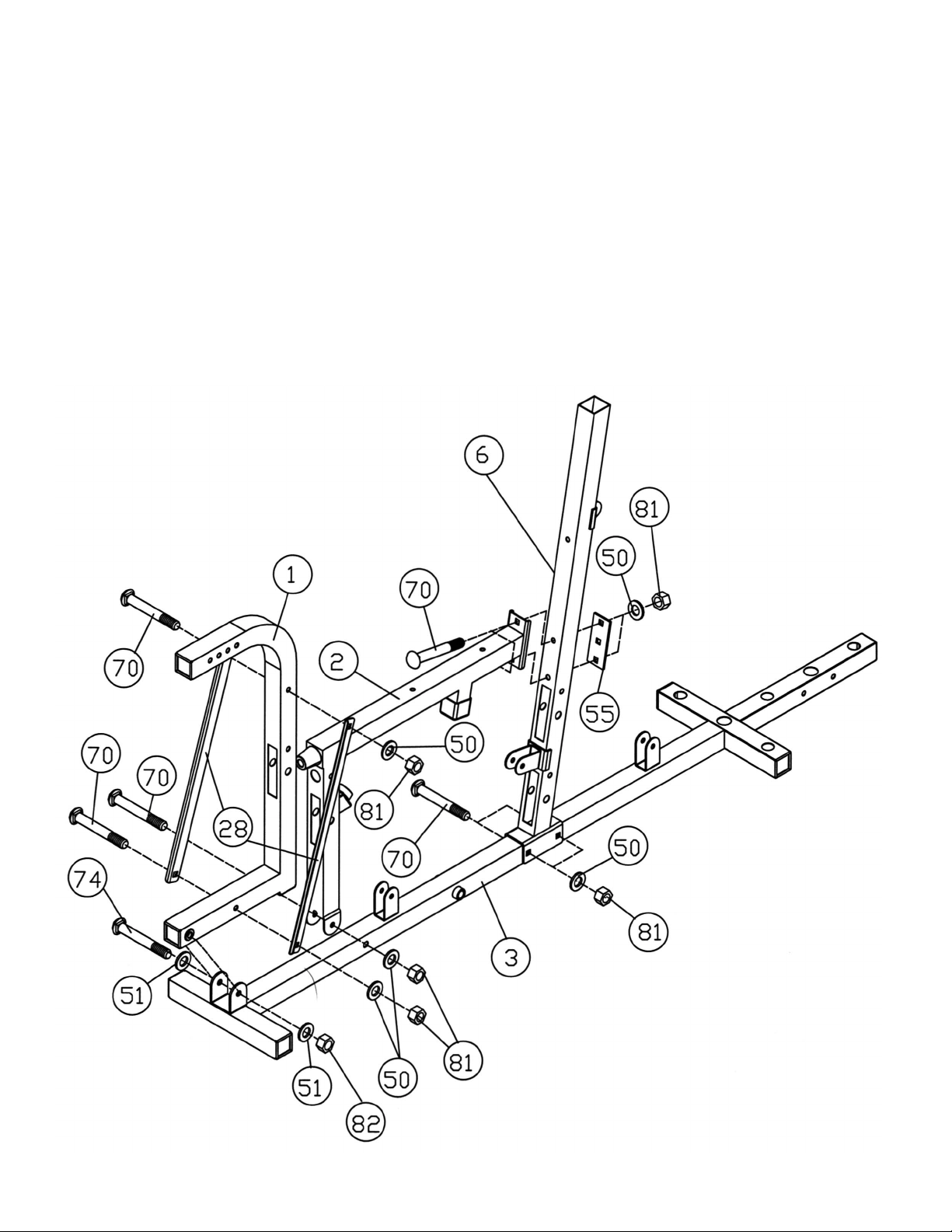
STEP 2 (See Diagram 2)
A.) Attach Right Vertical Beam (#6) to the Right Base Frame (#3). Secure it with two M10 x 2
¾” Carriage Bolts (#70), ∅ ¾” Washers (#50), and M10 Aircraft Nuts (#81).
B.) Attach the Right Seat Support (#2) to the Right Base Frame (#3). Secure it with one M10
x 2 ¾” Carriage Bolt (#70), ∅ ¾” Washer (#50), and M10 Aircraft Nut (#81).
C.) Attach the Right Seat Support (#2) to the Right Vertical Beam (#6). Secure it with two
M10 x 2 ¾” Carriage Bolts (#70), ∅ ¾” Washers (#50), and M10 Aircraft Nuts (#81).
D.) Attach the Leg Press Frame (#1) to the Right Base Frame (#3). Secure it with one M12 x
3” Allen Bolt (#74), two ∅ 1” Washers (#51), and one M12 Aircraft Nut (#82). NOTE: Do
not over tighten the bolt. Make sure the Leg Press Frame is able to swivel.
E.) Attach the Leg Press Support Frames (#28) to both sides of the Leg Press Frame (#1).
Secure them together with two M10 x 2 ¾” Carriage Bolts (#70), ∅ ¾” Washers (#50),
and M10 Aircraft Nuts (#81).
DIAGRAM 2
5
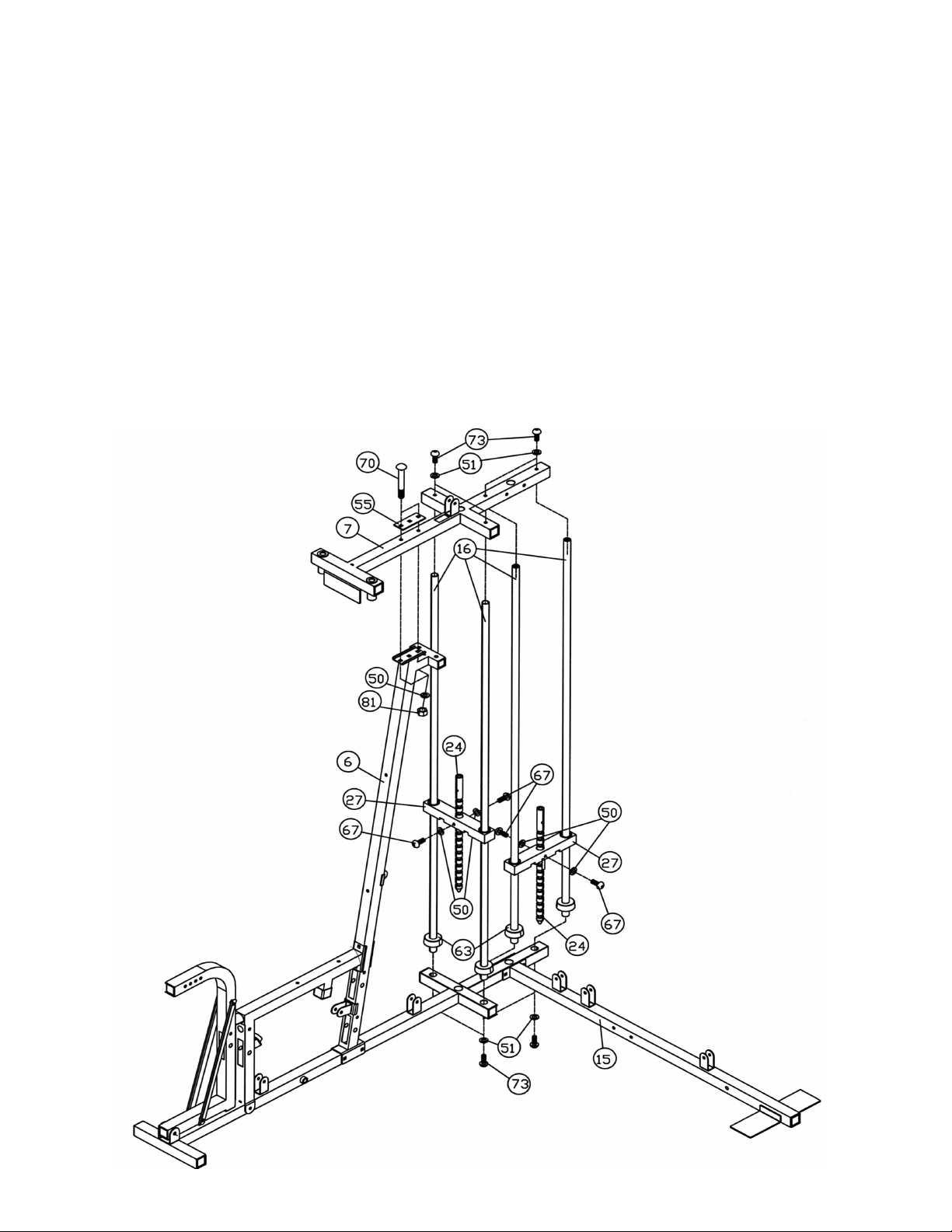
STEP 3 (See Diagram 3)
A.) Align four ∅1” Rubber Bumpers (#63) to the holes on the Right Base Frame (#3). Insert the
four Guide Rods (#16) through the Rubber Bumpers into the holes on the Right Base Frame
(#3). Slide two Selector Stems (#27) onto the Guide Rods. Insert a Selector Rod (#24)
through the hole on each Selector Stem (#27). Secure each Selector Rod (#24) to the
Selector Stem (#27) with two M10 x 1” Allen Bolts (#67) and ∅ ¾” Washers (#50). Please
note this machine comes with 18 plates, 9 to each stack. You can purchase another 5 more
plates (Model no. WK51) in the future to increase the weights. It is strongly recommended to
spay lubricant such as WD-40 on the two Guide Rods to minimize friction.
B.) Attach the Right Upper Frame (#7) to the top of Right Vertical Beam (#6), and the four Guide
Rods (#16). Make sure the Guide Rods are inserted into the holes on the Upper Frame.
C.) Secure the Upper Frame (#7) to the Right Vertical Beam (#6) with one Bracket (#55), two
M10 x 2 ¾” Carriage Bolts (#70), ∅ ¾” Washers (#50), and M10 Aircraft Nuts (#81).
D.) Secure the Upper Frame to the Guide Rods with four M12 x 1” Allen Bolts (#73) and ∅ 1”
Washers (#51).
E.) Carefully tip over the machine with a help of another person. Secure the Guide Rods (#16)
to the Right Base Frame (#3) with four ∅1” Washers (#51) and M12 x 1” Allen Bolts (#73).
6
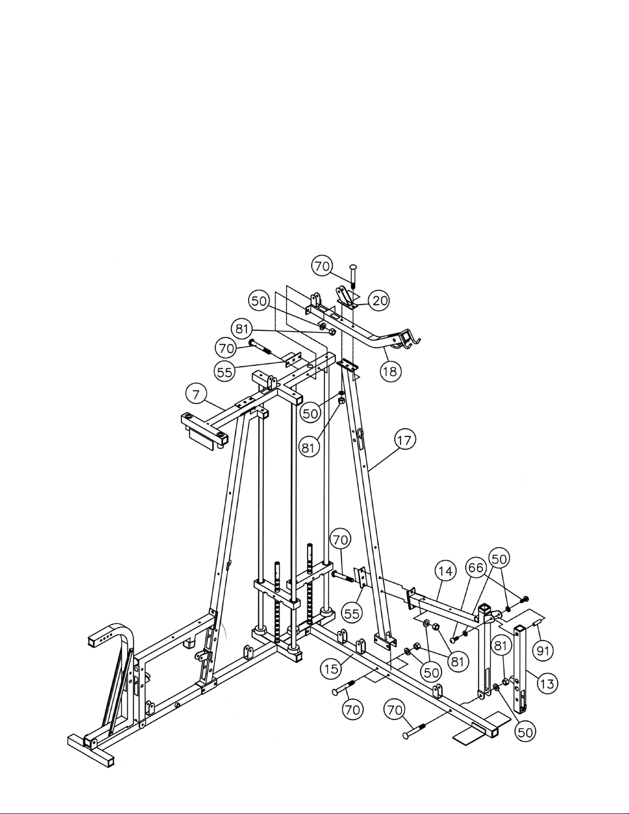
STEP 4 (See Diagram 4)
A.) Attach the Left Vertical Beam (#17) to the Left Base Frame (#15). Secure it with two M10 x
2 ¾” Carriage Bolts (#70), ∅ ¾” Washers (#50), and M10 Aircraft Nuts (#81).
B.) Attach the Left Upper Frame (#18) to the Left Vertical Beam (#17), and the Right Upper
Frame (#7). Secure the Frame to the Vertical Beam with one Pulley Bracket (#20), two M10
x 2 ¾” Carriage Bolts (#70), two ∅ ¾” Washers (#50), and two M10 Aircraft Nuts (#81).
Secure the Left Frame to the Right Frame with one Bracket (#55), two M10 x 2 ¾” Carriage
Bolts (#70), two ∅ ¾” Washers (#50), and two M10 Aircraft Nuts (#81).
C.) Attach the Left Seat Support (#14) to the Left Base Frame (#15) and the Left Vertical Beam
(#17). Secure the Seat Support to the Left Base Frame with one M10 x 2 ¾” Carriage Bolt
(#70), ∅ ¾” Washer (#50), and M10 Aircraft Nut (#81). Secure the Seat Support to the
Vertical Beam with one Bracket (#55), two M10 x 2 ¾” Carriage Bolts (#70), ∅ ¾” Washers
(#50), and M10 Aircraft Nuts (#81).
D.) Attach the Leg Developer (#13) to the bracket on the Left Seat Support (#14). Secure it with
one M10 x 2” Axle (#91), two M10 x ¾” Allen Bolts (#66) and ∅ ¾” Washers (#50).
7
 Loading...