

Page 1
NOTE:
Please read all instructions
carefully before using this
product
Table of Contents
Safety Notice
Hardware Identifier
Assembly Instruction
Parts List
Warranty
Ordering Parts
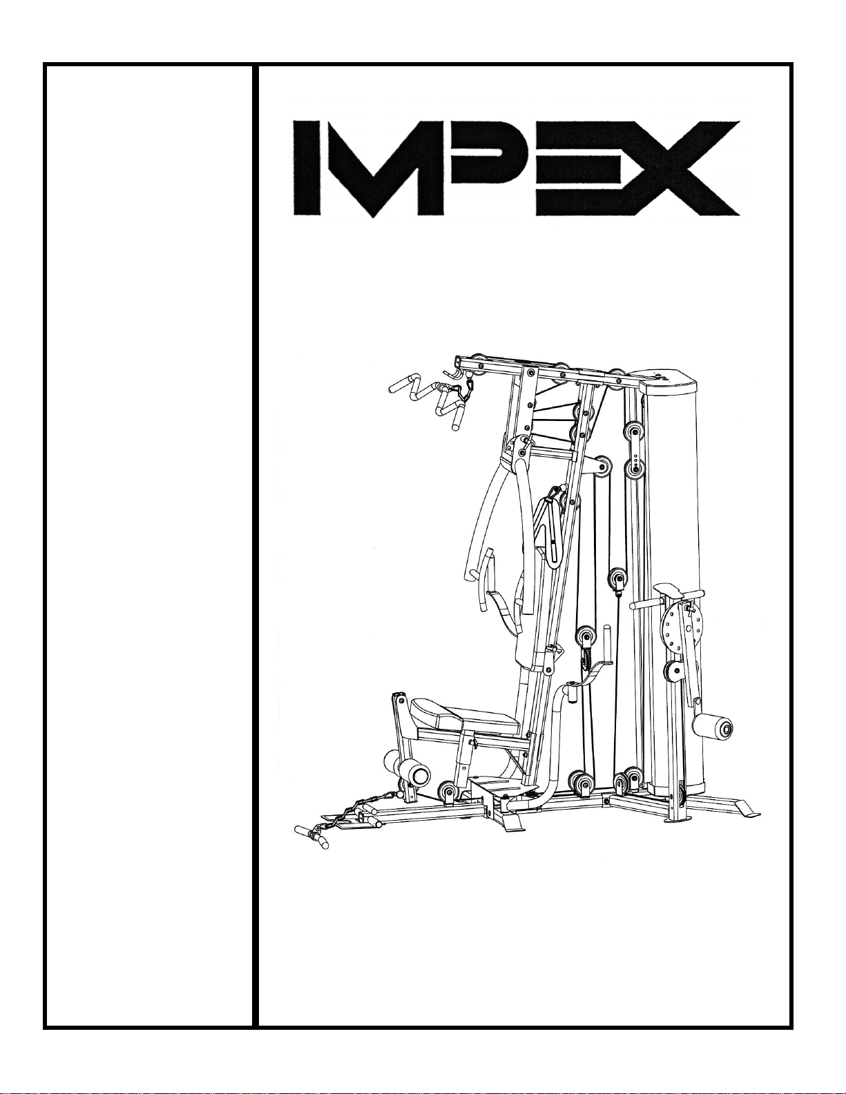
MARCY PLATINUM
MP-3500 HOME GYM
Model
MP-3500
Retain This
Manual for
Reference
11-14-07
OWNER'S
MANUAL
IMPEX® INC.
14777 DON JULIAN RD., CITY OF INDUSTRY, CA 91746
Tel: (800) 999-8899 Fax: (626) 961-9966
www.impex-fitness.com
Page 2

TABLE OF CONTENTS
BEFORE YOU BEGIN...................................................................................... 1
IMPORTANT SAFETY NOTICES..................................................................... 2
HARDWARE PACK……….....…....................................................................... 4
ASSEMBLY INSTRUCTIONS........................................................................... 7
WEIGHT RESISTANCE CHART....................................................................... 28
PARTS LIST………………………………………………………………………….. 29
WARRANTY.................................................................................................… 30
ORDERING PARTS......................................................................................... 30
BEFORE YOU BEGIN
Thank you for selecting the MARCY PLATINUM MP-3500 HOME GYM by
IMPEX
®
INC. For your safety and benefit, read this manual carefully before
using the machine. As a manufacturer, we are committed to provide you
complete customer satisfaction. If you have any questions, or find there are
missing or damaged parts, we guarantee you complete satisfaction through
direct assistance from our factory. To avoid unnecessary delays, please call
our TOLL-FREE customer service number. Our Customer Service Agents
will provide immediate assistance to you.
Toll-Free Customer Service Number
1-800-999-8899
Mon. - Fri. 9 a.m. - 5 p.m. PST
www.impex-fitness.com
1
Page 3

IMPORTANT SAFETY NOTICE
PRECAUTIONS
This exercise machine is built for optimum safety. However, certain precautions apply
whenever you operate a piece of exercise equipment. Be sure to read the entire manual
before you assemble or operate your machine. In particular, note the following safety
precautions:
1. Keep children and pets away from the machine at all times. DO NOT
leave children unattended in the same room with the machine.
2. Only one person at a time should use the machine.
3. If the user experiences dizziness, nausea, chest pain, or any other abnormal
symptoms, STOP the workout at once. CONSULT A PHYSICIAN IMMEDIATELY.
4. Position the machine on a clear, leveled surface. DO NOT use the machine
near water or outdoors.
5. Keep hands away from all moving parts.
6. Always wear appropriate workout clothing when exercising. DO NOT wear
robes or other clothing that could become caught in the machine. Running
or aerobic shoes are also required when using the machine.
7. Use the machine only for its intended use as described in this manual. DO
NOT use attachments not recommended by the manufacturer.
8. Do not place any sharp object around the machine.
9. Disabled person should not use the machine without a qualified person or
physician in attendance.
10. Before using the machine to exercise, always do stretching exercises to
properly warm up.
11. Never operate the machine if the machine is not functioning properly.
CARE AND MAINTENANCE
1. Lubricate moving parts with WD-40 or light oil periodically.
2. Inspect and tighten all parts before using the machine.
3. The machine can be cleaned using a damp cloth and mild non-abrasive detergent.
DO NOT use solvents.
4. Maximum user’s weight: 300 lbs.
WARNING: BEFORE BEGINNING ANY EXERCISE PROGRAM, CONSULT YOUR
PHYSICIAN. THIS IS ESPECIALLY IMPORTANT FOR INDIVIDUALS OVER THE AGE OF
35 OR PERSONS WITH PRE-EXISTING HEALTH PROBLEMS. READ ALL
INSTRUCTIONS BEFORE USING ANY FITNESS EQUIPMENT. IMPEX INC. ASSUMES
NO RESPONSIBILITY FOR PERSONAL INJURY OR PROPERTY DAMAGE SUSTAINED
BY OR THROUGH THE USE OF THIS PRODUCT.
SAVE THESE INSTRUCTIONS.
2
Page 4

WARNING LABEL REPLACEMENT
The warning labels shown here have been placed on the Rear Stabilizer and Upper Frame. If the labels are
missing or illegible, please call customer service at 1-800-888-8899 for replacements. Apply the labels in
location shown.
3
Page 5
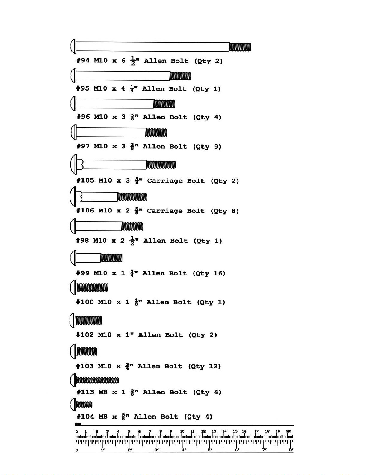
HARDWARE PACK
NOTE: The following parts are not drawn to scale. Please use your own ruler to measure the size.
4
Page 6
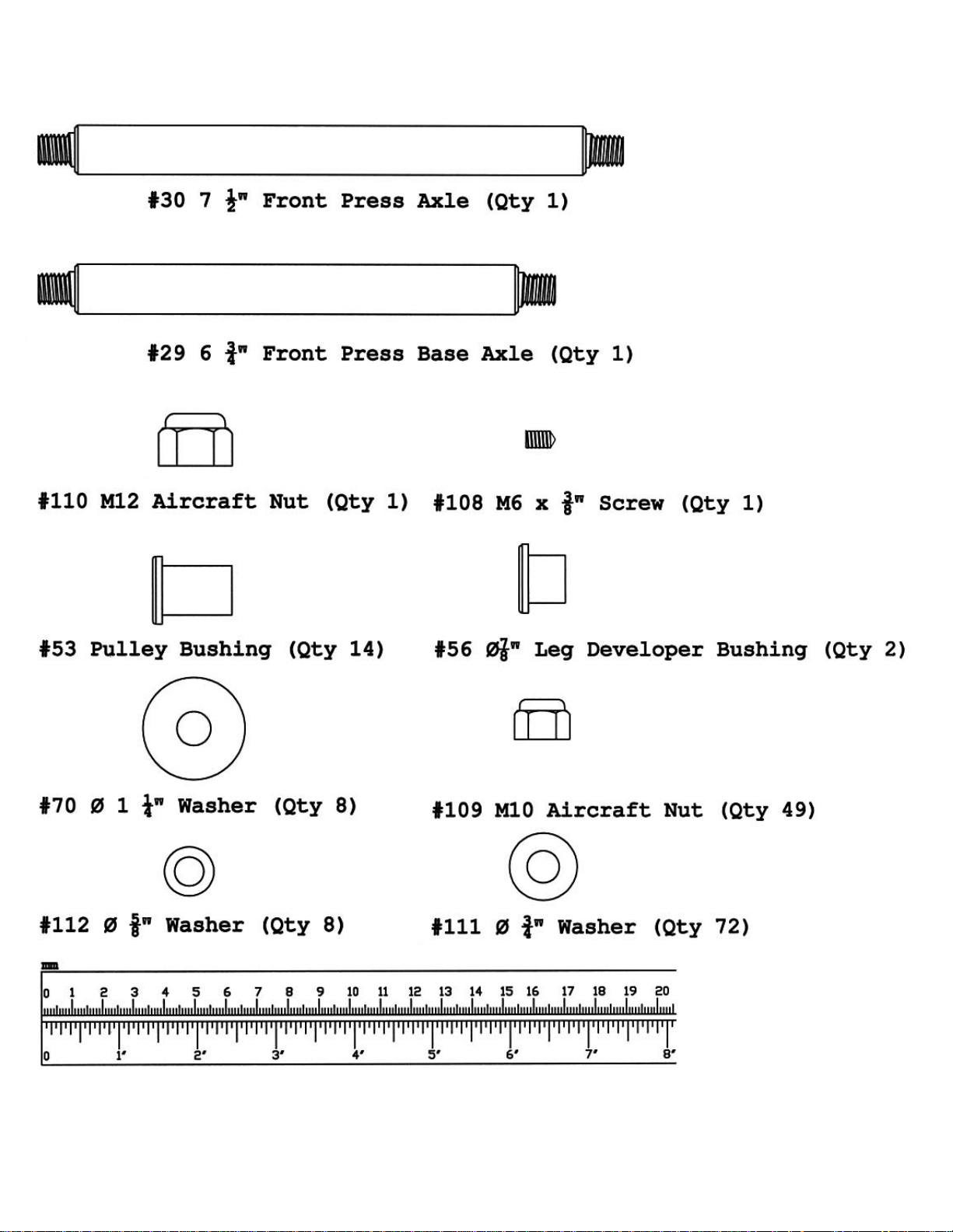
HARDWARE PACK
NOTE: The following parts are not drawn to scale. Please use your own ruler to measure the size.
5
Page 7
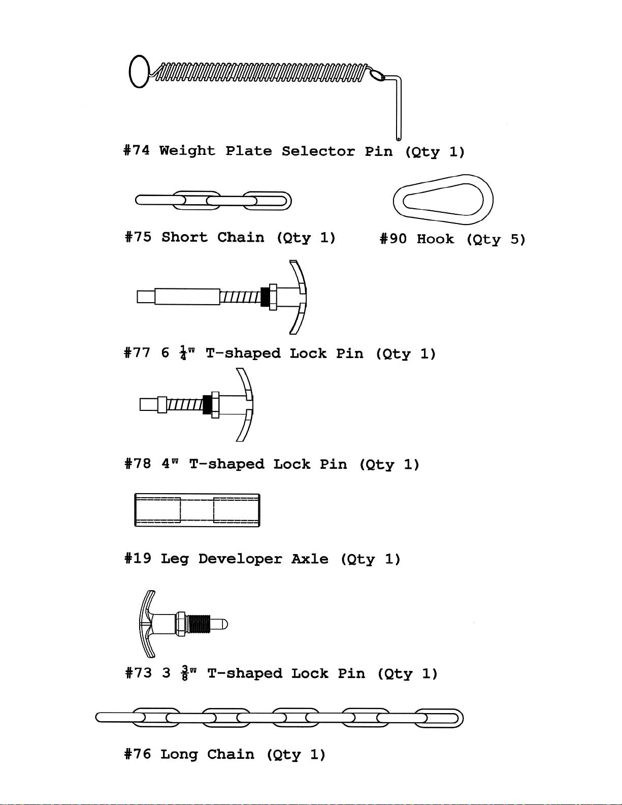
HARDWARE PACK
6
Page 8

ASSEMBLY INSTRUCTION
Tools Required Assembling the Machine: Two Adjustable Wrenches and Allen
Wrenches
NOTE: It is strongly recommended this machine be assembled by two or more people
to avoid possible injury.
STEP 1 (See Diagram 1)
A.) Place a Weight Stack Cover Base (#68) onto the Rear Stabilizer (#16). Secure it to the
Rear Stabilizer with two M8 x 5/8” Allen Bolts (#104) and Ø 5/8” Washers (#112). Insert
two Guide Rods (#17) through the holes on the Weight Stack Cover Base into the Rear
Stabilizer. Secure each Guide Rod with one M10 x ¾” Allen Bolt (#103) and Ø ¾”
Washer (#111) from the bottom. Slide two Ø 2 3/8” x 1” Rubber Bumpers (#52) onto the
two Guide Rods.
B.) Do not tighten the Nuts and Bolts in the following procedures until instructed to do so.
C.) Attach the Vertical Frame (#4) onto the Rear Base Frame (#15). Secure it with two M10
x 2 5/8” Carriage Bolts (#106), one 4 ¾” x 2 ¾” Bracket (#25), two ∅ ¾” Washers
(#111), and two M10 Aircraft Nuts (#109).
D.) Attach the Butterfly Base (#13) to the Rear Base Frame (#15). Attach the Front Base
Frame (#12) to the Butterfly Base (#13). Make sure the L shaped bracket welded on the
Butterfly Base (#13) face towards the front of the machine (see small diagram in the
square insert in Diagram 1). Align the holes and secure them together with two M10 x 2
5/8” Carriage Bolts (#106) from the bottom, two M10 x 3 5/8” Carriage Bolts (#105) from
the side of Butterfly Base, four Ø ¾” Washers (#111), and four M10 Aircraft Nuts (#109).
E.) Connect the Rear Base Frame (#15) to the Rear Stabilizer (#16). Secure them together
with two M10 x 3 5/8” Allen Bolts (#96), two Ø ¾” Washers (#111), and one 2 ¾” x 1 ½”
Bracket (#36).
F.) Attach the Foot Plate (#14) to the Front Base Frame (#12). Align the holes and insert the
Foot Plate Axle (#37) through the holes.
G.) Slide 14 Weight Plates (#80) onto the Guide Rods. Make sure the deep groves on all
Plates face down and toward the back. Insert the Selector Rod (#17) through the center
hole on the Weight Plates. Slide the Weight Selector Stem (#81) onto the Guide Rods.
H.) Use the Weight Plate Selector Pin (#74) to select desired number of Weight Plates to
exercise. NOTE: Each Plate weights approximately 10 lbs. Please refer to the Weight
Resistance Chart on page 28.
7
Page 9
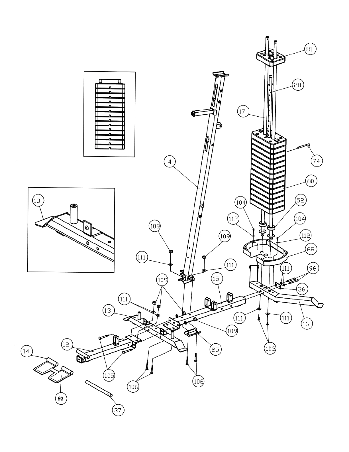
DIAGRAM 1
8
Page 10
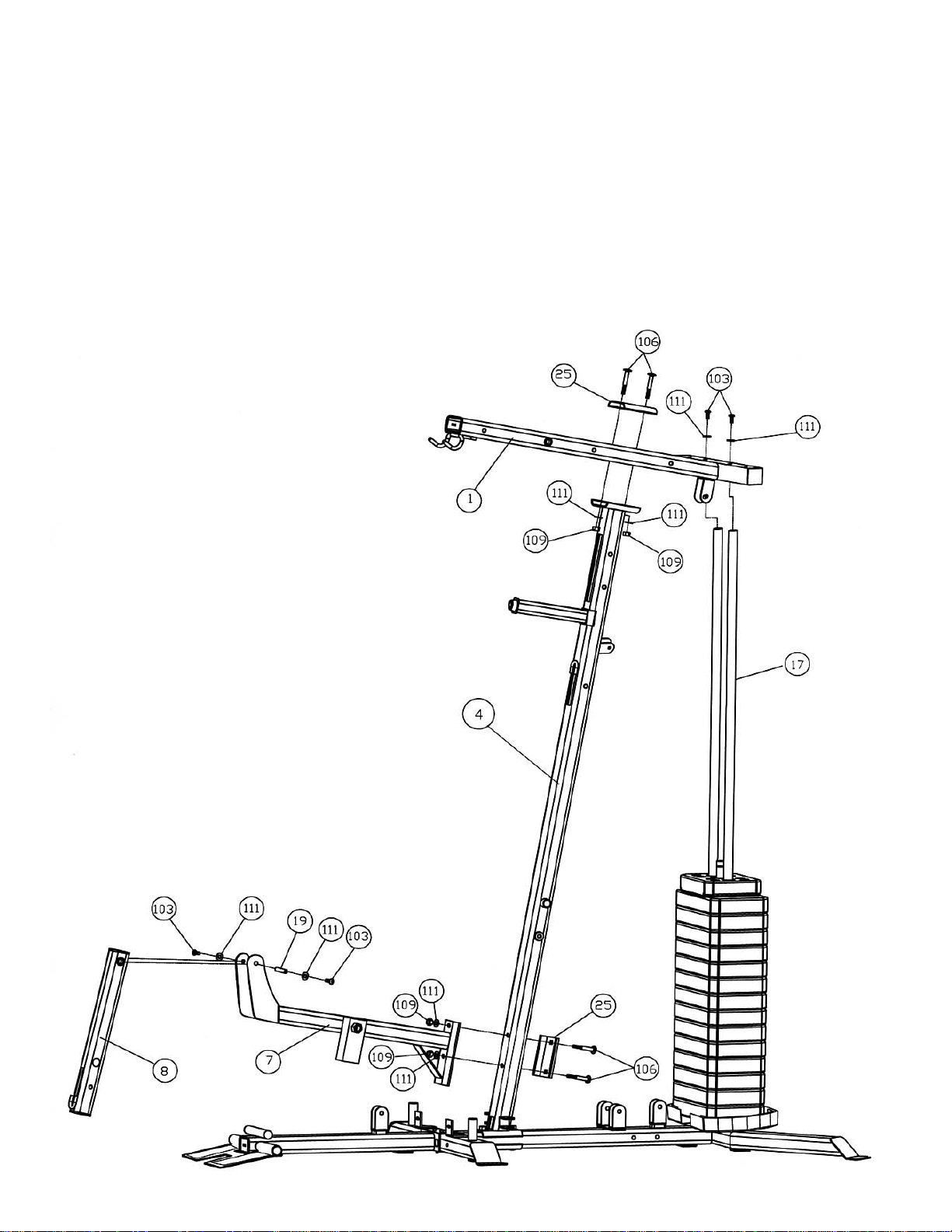
STEP 2 (See Diagram 2)
A.) Attach the Upper Frame (#1) onto the two Guide Rods (#17). Secure it with two M10 x
¾” Allen Bolts (#103) and ∅ ¾” Washers (#111). DO NOT tighten the Bolts yet.
B.) Place the Upper Frame onto the Vertical Frame (#4). Secure it with two M10 x 2 5/8”
Carriage Bolts (#106), one 4 ¾” x 2 ¾” Bracket (#25), two ∅ ¾” Washers (#111), and
two M10 Aircraft Nuts (#109).
C.) Securely tighten all Nuts and Bolts previously installed.
D.) Attach the Seat Support Frame (#7) to the Vertical Frame (#4). Secure it with two M10 x
2 5/8” Carriage Bolts (#106), one 4 ¾” x 2 ¾” Bracket (#25), two ∅ ¾” Washers (#111),
and two M10 Aircraft Nuts (#109).
E.) Attach the Leg Developer (#8) to the bracket on the Seat Support Frame. Secure it with
one Leg Developer Axle (#19), two M10 x ¾” Allen Bolts (#103), and two Ø ¾” Washers
(#111). Do not over tighten the Bolts. Make sure the Leg Developer is able to swivel.
9
Page 11

STEP 3 (See Diagram 3)
A.) Attach the Front Press Base (#2) to the Upper Frame (#1). Secure it with one 6
¾” Front Press Base Axle (#29), two Ø 1 ¼” Washers (#70), and two M10
Aircraft Nuts (#109).
B.) Attach the Front Press (#3) to the Front Press Base. Secure it with one 7 ½”
Front Press Axle (#30), two Ø1 ¼” Washers (#70), and two M10 Aircraft Nuts
(#109).
C.) Thread the 4” T-shaped Lock Pin (#78) into the hole on the Front Press to
obtain the desired Front Press position.
D.) Attach the Backrest Board (#89) to the Backrest Support Frame (#5). Secure it
with two M8 x 1 5/8” Allen Bolts (#113) and Ø 5/8” Washers (#112).
E.) Attach the Backrest Support Frame (#5) to the Vertical Frame (#4). Secure it
with one M10 x 4 ¼” Allen Bolt (#95), two ∅ ¾” Washers (#111), and one M10
Aircraft Nut (#109).
F.) Thread the 6 ¼” T-shaped Lock Pin (#77) into the hole on the side of the
Vertical Frame to obtain the desired Backrest position.
10
Page 12
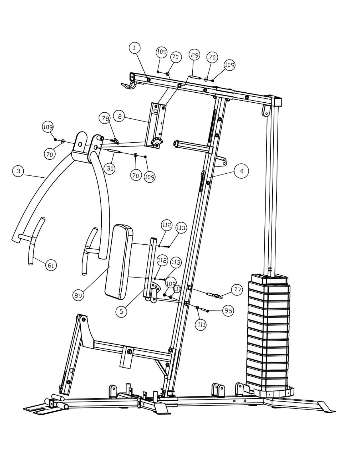
DIAGRAM 3
11
Page 13

STEP 4 (See Diagram 4)
A.) Attach the Seat Pad (#88) to the Seat Post (#6). Secure it with two M8 x 1 5/8” Allen
Bolts (#113) and Ø 5/8” Washers (#112).
B.) Insert the Seat Post into the opening on the Seat Support Frame (#7). Thread the 3
3/8” T-shaped Lock Pin (#73) into the nut on the Seat Support Frame to lock the
Seat at desired height.
C.) Insert one Foam Tube (#23) halfway through the hole on the Leg Developer (#8).
Push two Foam Rolls (#86) onto the Foam Tube from both ends. Plug two Foam Roll
End Caps (#59) into the Ends.
D.) Attach the Leg Machine Frame (#31) to the Rear Base Frame (#15). Secure it with
two M10 x 3 5/8” Allen Bolts (#96), one 5 ½” x 2” Bracket (#26), four Ø ¾” Washers
(#111), and two M10 Aircraft Nuts (#109).
E.) Attach the Rotating Cam Plate (#32) to the Leg Machine Frame (#31). Align the
holes and insert the axle on the Lever Frame (#33) through the holes. Secure it with
one Ø 1 ¼” Washer (#70) and one M12 Aircraft Nut (#110). Do not over tighten the
nut. The Lever Frame needs to swivel freely on the pivot.
F.) Adjust and secure the Lever Frame (#33) to the Cam (#32) with a 4” T-shaped Lock
Pin (#78).
G.) Insert the axle on the Lever Frame Handle (#34) into the opening on the Lever
Frame (#33). Secure it with one Ø 1 ¼” Washer (#70) and M10 Aircraft Nut (#109).
H.) Slide a 7” Swivel Tube Sleeve (#38) onto the tube on the Lever Frame Handle (#34).
I.) Push one Ø 4” Large Foam Roll (#58) onto Sleeve. Plug one Foam Roll End Cap
(#59) into the end of Handle.
J.) Slide one Foam Tube (#23) halfway through the hole on the Leg Machine Frame
(#31). Secure it with one M6x 3/8” Screw (#108). Push the 6 7/8” Grips (#67) onto
the Tube.
12
Page 14
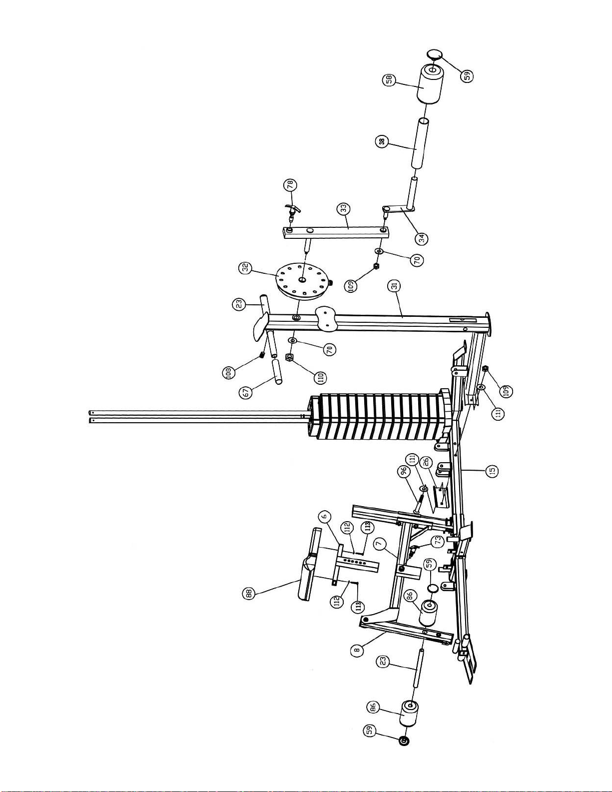
DIAGRAM 4
13
Page 15
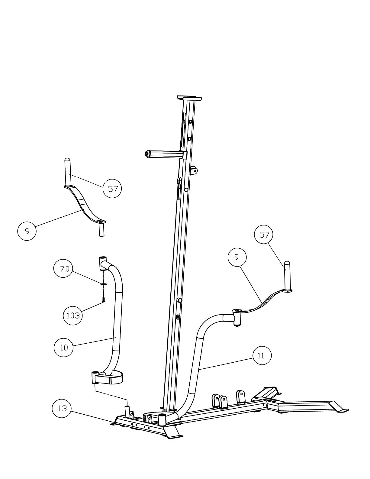
STEP 5 (See Diagram 5)
A.) Slide the Right Butterfly (#10) onto the right axle on the Butterfly Base (#13).
B.) Insert the Butterfly Handle (#9) into the pivot on the Right Butterfly. Secure it with one M10
x ¾” Allen Bolt (#103) and ∅ 1 ¼” Washer (#70) from the bottom.
C.) Repeat Procedures A and B above to install the other side. Do not over tighten the Bolts.
Make sure the Handles are able to swivel.
DIAGRAM 5
14
Page 16

STEP 6 (See Diagram 6 & Upper Cable Loop Diagram)
A.) Attach the 167” Upper Cable (#42) to the opening on the front of Upper Frame (#1).
Make sure the ball stopper is underneath the Frame. Attach a Pulley (#44) to the Cable.
B.) Secure the Pulley to the opening with one M10 x 3 3/8” Allen Bolt (#97), two Pulley
Bushings (#53), and one M10 Aircraft Nut (#109).
C.) Draw the Cable over the Pulley along the Upper Frame towards the back of the
machine to the opening in the middle of Upper Frame. Repeat Procedure B above to
install a Pulley.
D.) Draw the Cable around the Pulley then back to the upper opening on the Front Press
Base (#2). Attach a Pulley to the opening. Secure it with one M10 x 6 ½” Allen Bolt
(#94), two ∅ ¾” Washers (#111), and one M10 Aircraft Nut (#109).
E.) Draw the Cable around the Pulley then towards the upper opening on the Vertical
Frame (#4). Repeat Procedure B above to install a Pulley.
F.) Draw the Cable around the Pulley and back to the lower opening on the Front Press
Base. Repeat Procedure D above to install a Pulley.
G.) Draw the Cable around the Pulley then to the lower opening on the Vertical Frame.
Repeat Procedure B above to install a Pulley.
H.) Draw the Cable underneath the Pulley then pull upward to another opening on the back
of the Upper Frame. Repeat Procedure B above to install a Pulley.
I.) Draw the Cable around the Pulley then downward. Attach a Pulley to the top hole on
the Double Floating Pulley Brackets (#20).
J.) Secure the Pulley to the brackets with one M10 x 1 ¾” Allen Bolt (#99), two Ø ¾”
Washers (#111), and one M10 Aircraft Nut (#109). Let the Bracket hanging for now.
K.) Draw the Cable around the Pulley then upward to the open bracket between the two
Guide Rods. Repeat Procedure J above to install a Pulley.
L.) Draw the Cable around the Pulley then downward to the Selector Rod (#28). Securely
thread the Head Bolt at end of the Cable into the Selector Rod.
15
Page 17
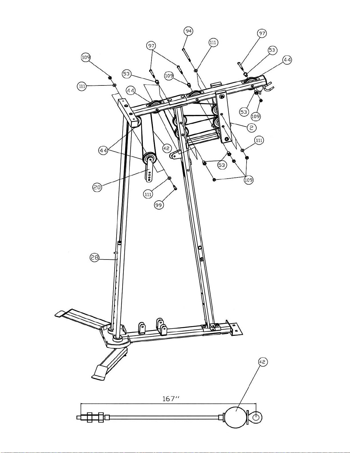
DIAGRAM 6
16
Page 18
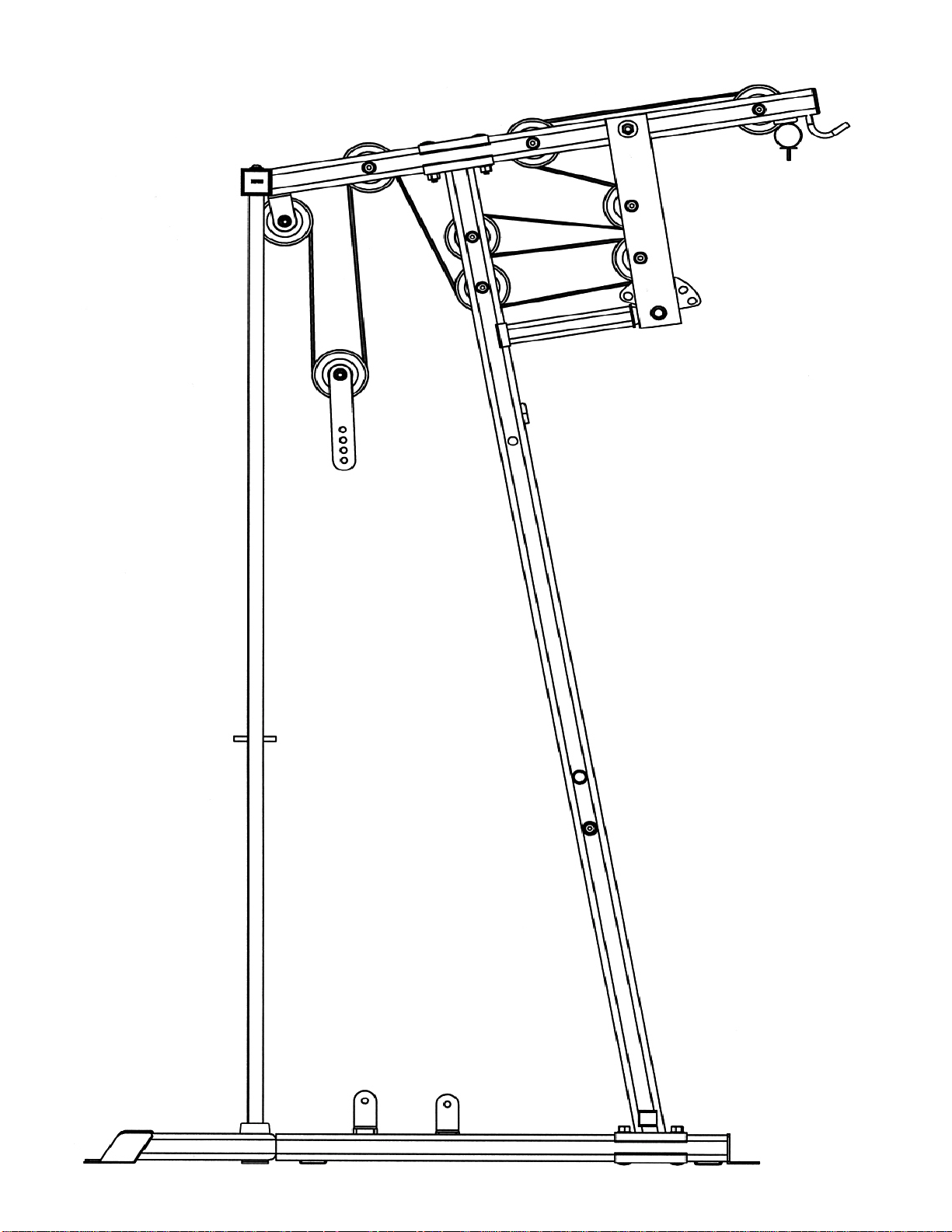
Upper Cable Loop Diagram
17
Page 19

STEP 7 (See Diagram 7 & Lower Cable Loop Diagram)
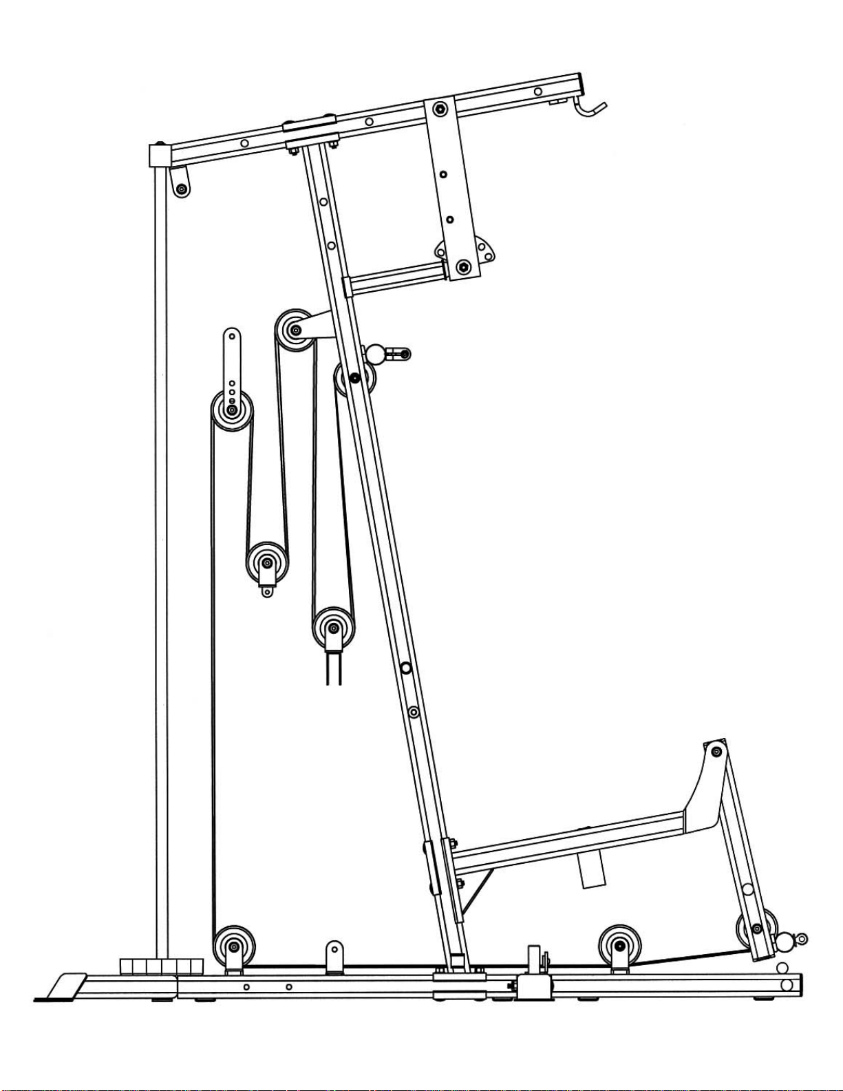
A.) Attach the 217” Lower Cable (#40) to the opening on the Leg Developer (#8). Attach
a Pulley (#44) to the opening. Secure it with one M10 x 2 ½” Allen Bolt (#98), two ∅
7/8” Leg Developer Pulley Bushings (#56), and one M10 Aircraft Nut (#109).
B.) Draw the Cable underneath the Pulley to the open bracket on the Front Base Frame
(#12). Attach a Pulley to the bracket. Secure it with one M10 x 1 ¾” Allen Bolt (#99),
two ∅ ¾” Washers (#111), and one M10 Aircraft Nut (#109).
C.) Draw the Cable underneath the Pulley towards the back of the machine through the
bottom opening on the Vertical Frame (#4) to the open bracket on the Rear Base
Frame (#15). Repeat Procedure B above to install a Pulley.
D.) Draw the Cable underneath the Pulley then pull upward to the Double Floating Pulley
Bracket (#20) previously installed in STEP-6. Repeat Procedure B above to install a
Pulley. After completing the entire cable system, come back to the Double Floating
Pulley Bracket and adjust the height of the lower Pulley to adjust the tightness of the
Cables. Move up the pulley to increase the tension. Move down the pulley to loose
the tension.
E.) Draw the Cable around the Pulley then downward. Attach the Cable to a Single
Floating Pulley Bracket (#18). Repeat Procedure B to install a Pulley.
F.) Draw the Cable around the Pulley then upward to the open bracket on the back of
Vertical Frame (#4). Repeat Procedure B to install a Pulley.
G.) Draw the Cable around the Pulley then downward. Attach the Cable to an Angled
Double Floating Pulley Bracket (#27). Repeat Procedure B above to install a Pulley.
Let the Brackets hanging for now.
H.) Draw the Cable around the Pulley then upward to the opening on the Vertical Frame
(#4). Attach a Pulley to the opening. Secure it with one M10 x 3 3/8” Allen Bolt
(#97), two Pulley Bushings (#53), and one M10 Aircraft Nut (#109).
I.) Insert the Cable through a Ball Stopper (#47). Attach the Cable to a U-shape Cable
Connector (#48). Secure the Connector with one M10 x 1 1/8” Allen Bolt (#100), two
∅ ¾” Washers (#111), and one M10 Aircraft Nut (#109).
18
Page 20
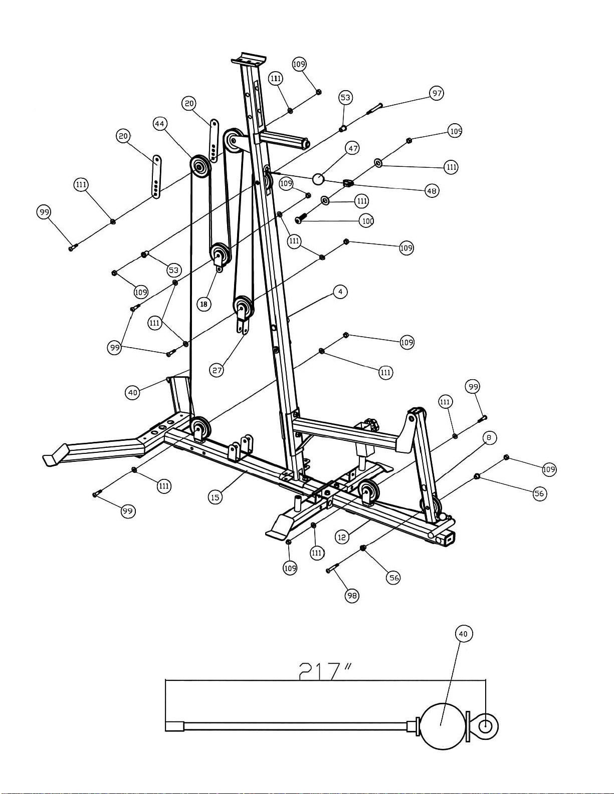
DIAGRAM 7
19
Page 21
Lower Cable Loop Diagram
20
Page 22

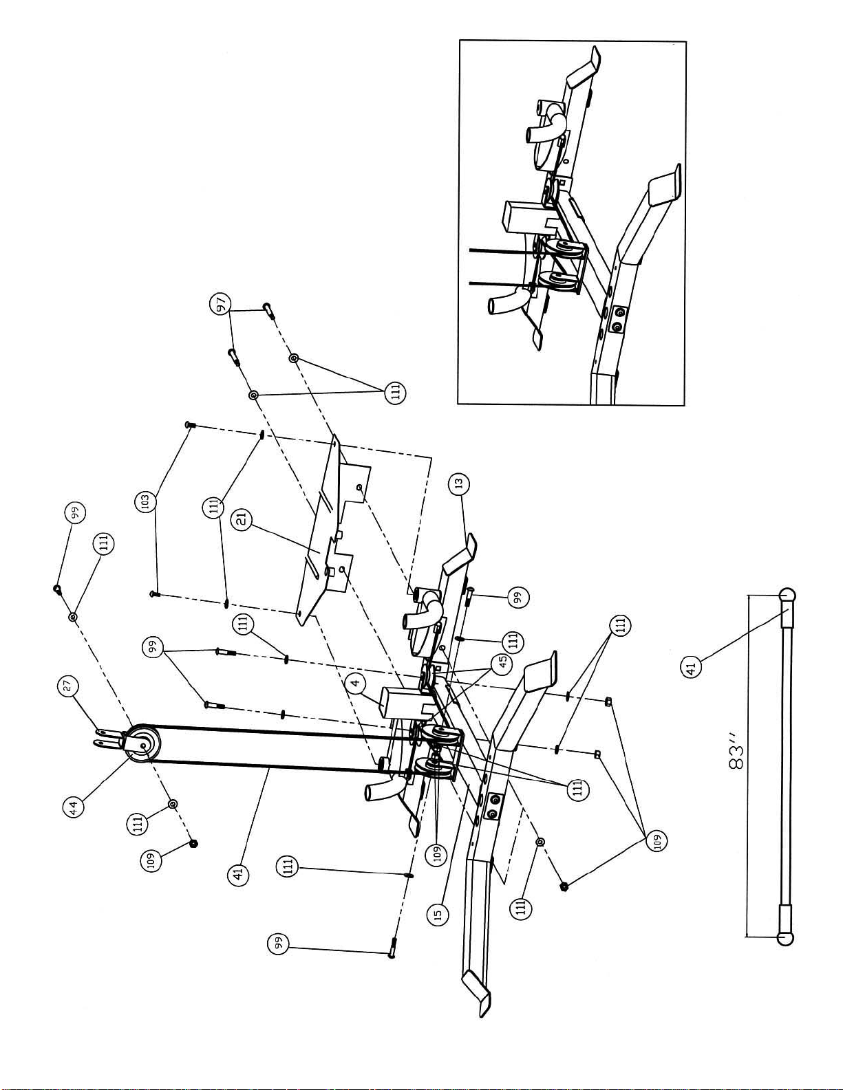
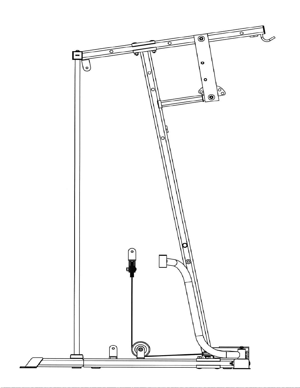
STEP 8 (See Diagram 8 & Butterfly Cable Loop Diagram)
A.) Clip one end of the 83” Butterfly Cable (#41) to the open slot on the Right Butterfly (#10).
B.) Draw the Cable to the open bracket on the right side of the Vertical Frame (#4). Attach a
Small Pulley (#45) to the bracket
C.) Secure it with one M10 x 1 ¾” Allen Bolt (#99), two Ø ¾” Washers (#111), and one M10
Aircraft Nut (#109).
D.) Draw the Cable around the Small Pulley to the right open bracket on the Rear Base
Frame (#15). Repeat Procedure C above to install a Pulley.
E.) Draw the Cable underneath the Pulley then upward to the Angled Double Floating Pulley
Bracket (#27) previously installed in Step-7. Repeat Procedure C above to install a Pulley.
F.) Draw the Cable around the Pulley then downward to the left open bracket on the Rear
Base Frame. Repeat Procedure C above to install a Pulley.
G.) Draw the Cable underneath the Pulley to the left open bracket on the Vertical Frame.
Install a Small Pulley to the bracket.
H.) Draw the Cable around the Small Pulley then attach the end the Cable to the open slot on
the Left Butterfly.
I.) Attach the Butterfly Base Cover (#21) to the Butterfly Base (#13) to cover the left and right
pivots on the Butterfly Base. Secure the Cover to the Pivots with two M10 x ¾” Allen Bolts
(#103) and Ø ¾” Washers (#11).
J.) Align the holes and secure the Cover to the Butterfly Base with two M10 x 3 3/8” Allen
Bolts (#97), four Ø ¾” Washers (#111), and two M10 Aircraft Nuts (#109).
21
Page 23
22
Page 24
Butterfly Cable Loop Diagram
23
Page 25
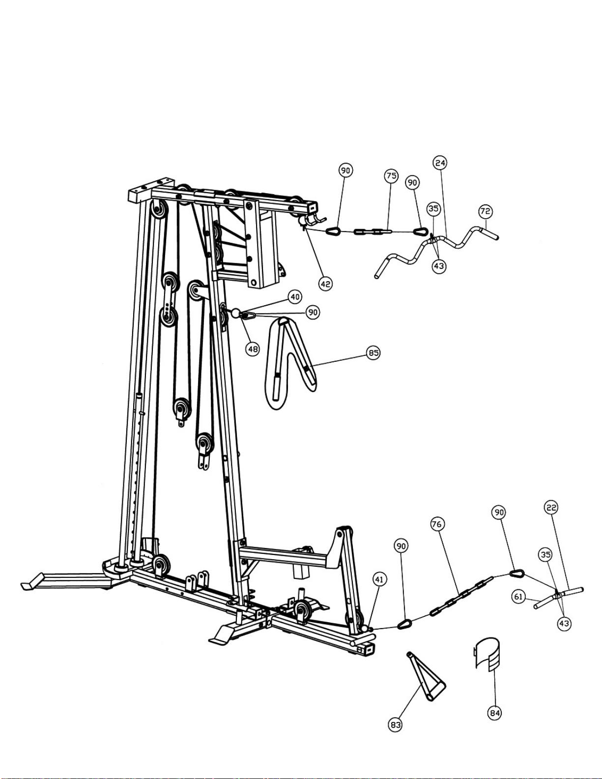
STEP 9 (See Diagram 9)
A.) Connect the Lat Bar (#24) to the 167” Upper Cable (#42) with two Hooks (#90) and one
Short Chain (#75).
B.) Attach the Abdominal Strap (#85) to the U-shaped Cable Connector (#48) on the 217”
Lower Cable (#40) with a Hook (#90).
C.) Connect the Shiver Bar (#22) to the 217” Lower Cable with two Hooks and a Long Chain
(#76).
DIAGRAM 9
24
Page 26
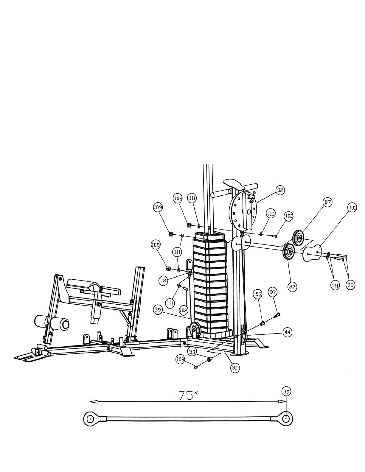
STEP 10 (See Diagram 10)
A.) Attach one end of 75” Hip-Thigh Cable (#39) to the bracket on the Rotating Cam Plate (#32).
Secure it with one M10 x 1” Allen Bolt (#102), two Ø ¾” Washers (#111), and one M10 Aircraft
Nut (#109).
B.) Attach two Medium Pulleys (#87) to the pulley bracket on the Leg Machine Frame (#31). Attach a
Double Pulley Bracket (#101) to the two Large Pulleys. Align the holes and secure them with two
M10 x 1 ¾” Allen Bolts (#99), four Ø ¾” Washers (#111), and two M10 Aircraft Nuts (#109).
C.) Draw the Cable between the two Large Pulleys and downward to the opening on the bottom of
the Frame. Attach a Pulley (#44) to the opening. Secure Pulley to the opening with one M10 x 3
3/8” Allen Bolt (#97), two Pulley Bushings (#53), and one M10 Aircraft Nut (#109).
D.) Draw the Cable underneath the Pulley to the open bracket behind the Frame. Install a Pulley with
one M10 x 1 ¾” Allen Bolt (#99), two Ø ¾” Washers (#111), and one M10 Aircraft Nut (#109).
E.) Draw the Cable around the Pulley then upward to the Single Floating Pulley Bracket (#18)
previously installed in Step-7. Secure the end of Cable to the bracket with M10 x 1” Allen Bolt
(#102), two Ø ¾” Washers (#111), and one M10 Aircraft Nut (#109).
25
Page 27
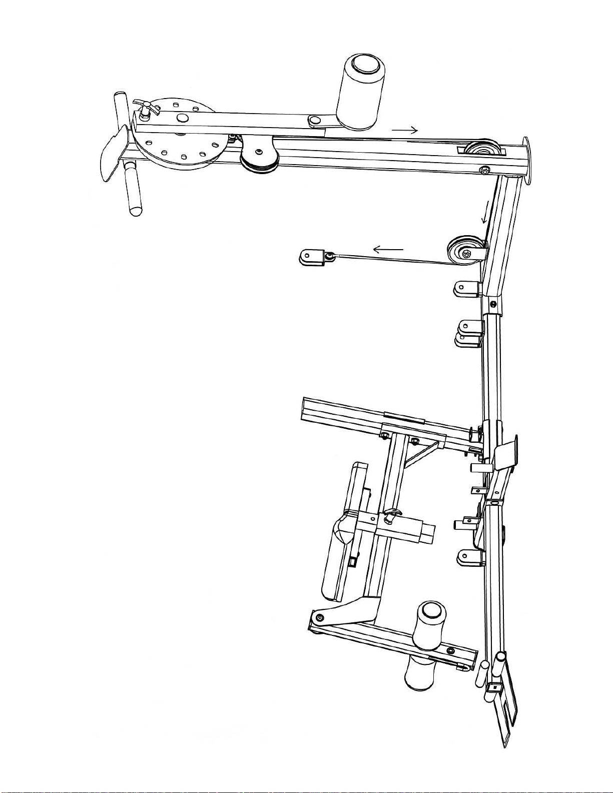
Hip-Thigh Cable Loop Diagram
26
Page 28
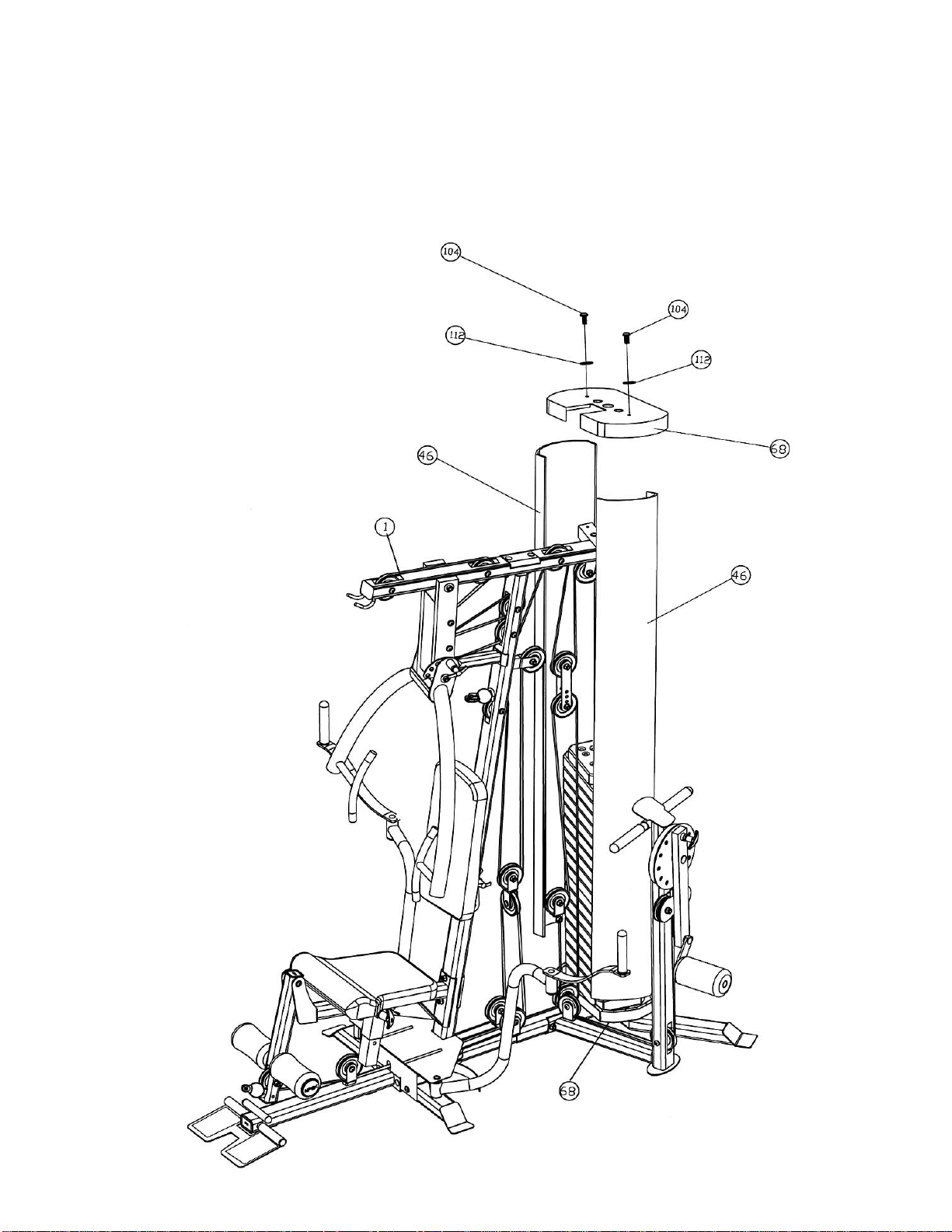
STEP 11 (See Diagram 11)
A.) Snap the bottom of the two Weight Stack Covers (#46) onto the Weight Stack Cover Base
(#68) previously installed in Step-1.
B.) Cover the top of the two Covers by another Weight Stack Cover Base. Make sure the top and
bottom of the two Covers are inside the Covers.
C.) Secure the Weight Stack Cover Base to the Upper Frame (#1) with two M8 x 5/8” Allen Bolts
(#104) and two Ø 5/8” Washers (#112). Please note that the Covers are flexible and might
get bent during transit. If the covers are not straight, bend the edge of the covers to make
them uniform.
27
Page 29

WEIGHT RESISTANCE CHART
Station 1 2 3 4 5 6 7 8 9
Low Pulley 20 30 40 50 60 70 80 90 100
Lat Pull 30 40 50 60 70 80 90 100 110
Butterfly 10 15 20 25 30 35 40 45 50
Front Press 20 35 50 65 80 95 110 125 140
AB Crunch 20 30 40 50 60 70 80 90 100
Leg Developer 20 30 40 50 60 70 80 90 100
Hip/Thigh 10 20 30 40 50 60 70 80 90
WEIGHT PLATE
WEIGHT PLATE
Station 10 11 12 13 14
Low Pulley 110 120 130 140 150
Lat Pull 120 130 140 150 160
Butterfly 55 60 65 70 75
Front Press 155 170 185 200 215
AB Crunch 110 120 130 140 150
Leg Developer 110 120 130 140 150
Hip/Thigh 100 110 120 130 140
*Numbers are approximate. Actual weight may vary.
*Numbers are approximate. Actual weight may vary.
*Numbers are approximate. Actual weight may vary.*Numbers are approximate. Actual weight may vary.
*Value for butterfly
*Value for butterfly is for each arm.
*Value for butterfly*Value for butterfly
is for each arm.
is for each arm. is for each arm.
28
Page 30

PARTS LIST
KEY NO. DESCRIPTION Q’ty
1 Upper Frame 1 61 5 3/8” Grip 6 2 Front Press Base 1 62 Ø 1” End Cap 4 3 Front Press 1 63 2” x 2” End Cap 2 4 Vertical Frame 1 64 1” x 2” End Cap 6 5 Backrest Support Frame 1 65 1” x 2 ¾” End Cap 4 6 Seat Post 1 66 2” x 2 ¾” End Cap 2 7 Seat Support Frame 1 67 6 7/8” Grip 2 8 Leg Developer 1 68 Weight Stack Cover Base 2 9 Butterfly Handle 2 69 ∅ 1 ¾” x 1 5/8” Rubber Bumper 1 10 Right Butterfly 1 70 ∅ 1 ¼” Washer 8 11 Left Butterfly 1 71 Ø 1” Rubber Bumper 2 12 Front Base Frame 1 72 6” Grip 4 13 Butterfly Base 1 73 3 3/8” T-shaped Lock Pin 1 14 Foot Plate 1 74 Weight Plate Selector Pin 1 15 Rear Base Frame 1 75 Short Chain 1 16 Rear Stabilizer 1 76 Long Chain 1 17 Guide Rod 2 77 6 ¼” T-shaped Lock Pin 1 18 Single Floating Pulley Bracket 1 78 4” T-shaped Lock Pin 1 19 Leg Developer Axle 1 79 Ø 2” End Cap 2 20 Double Floating Pulley Bracket 2 80 Weight Plate 14 21 Butterfly Base Cover 1 81 Selector Stem 1 22 Shiver Bar 1 82 Ø 1” Con-shaped End Cap 1 23 Foam Tube 2 83 Single Handle 1 24 Lat Bar 1 84 Ankle Strap 1 25 4 ¾” x 2 ¾” Bracket 3 85 Abdominal Strap 1 26 5 ½” x 2” Bracket 1 86 Foam Roll 2 27 Angled Double Floating Pulley Bracket 1 87 Medium Pulley 2 28 Selector Rod 1 88 Seat Pad 1 29 6 ¾” Front Press Base Axle 1 89 Backrest Board 1 30 7 ½” Front Press Axle 1 90 Hook 5 31 Leg Machine Frame 1 91 Plastic Edge Cover 4 32 Rotating Cam Plate 1 92 Foam Roll Vinyl Cover 3 33 Lever Frame 1 93 Foot Support Panel 2 34 Lever Frame Handle 1 94 M10 x 6 ½” Allen Bolt 2 35 Bar Handle Frame 2 95 M10 x 4 ¼” Allen Bolt 1 36 2 ¾” x 1 ½” Bracket 1 96 M10 x 3 5/8” Allen Bolt 4 37 Foot Plate Axle 1 97 M10 x 3 3/8” Allen Bolt 9 38 7” Swivel Tube Sleeve 1 98 M10 x 2 ½” Allen Bolt 1 39 75” Hip-Thigh Cable 1 99 M10 x 1 ¾” Allen Bolt 16 40 217” Lower Cable 1 100 M10 x 1 1/8” Allen Bolt 1 41 83” Butterfly Cable 1 101 Double Large Pulley Bracket 1 42 167” Upper Cable 1 102 M10 x 1” Allen Bolt 2 43 Bar Handle Frame Bushing 4 103 M10 x ¾” Allen Bolt 12 44 Pulley 21 104 M8 x 5/8” Allen Bolt 4 45 Small Pulley 2 105 M10 x 3 5/8” Carriage Bolt 2 46 Weight Stack Cover 2 106 M10 x 2 5/8” Carriage Bolt 8 47 Ball Stopper 1 107 M6 x 5/8” Screw 2 48 U-shaped Cable Connector 1 108 M6 x 3/8” Screw 1 49 Ø 1 ½” Rubber Bumper 1 109 M10 Aircraft Nut 49 50 Ø 1 Bushing 2 110 M12 Aircraft Nut 1 51 Ø 1 ½” Butterfly Bushing 8 111 Ø ¾” Washer 72 52 Ø 2 3/8” x 1” Rubber Bumper 2 112 Ø 5/8” Washer 8 53 Pulley Bushing 14 113 M8 x 1 5/8” Allen Bolt 4 54 Ø 1” x 3/8” Bushing 12 55 Ø 1 ¼” Front Press Bushing 2 56 Ø 7/8” Leg Developer Bushing 2 57 Butterfly Handle Grip 2 58 Ø 4” Large Foam Roll 1 59 Foam Roll End Cap 3 60 Ø 1 ¼” x ½” Bushing 4
29
Page 31

®
IMPEX
INC.
LIMITED WARRANTY
IMPEX Inc. ("IMPEX®") warrants this product to be free from defec ts in workmans hip and material, under norm al
use and service conditions, for a per iod of two years on the Frame from the date of purchase. This warranty
extends only to the original purchaser. IMPEX's obligation under this Warranty is limited to r eplacing or r epairing,
at IMPEX's option.
All returns must be pre-authorized by IMPEX. Pre-authorization may be obtained by calling IMPEX Customer
Service Department at 1-800-999-8899. All freights on products returned to IMPEX must be prepaid by the
customer. This warranty does not extend to any product or damage to a product caused by or attributable to
freight damage, abuse, misuse, improper or abnormal usage or repairs not provided by an IMPEX authorized
service center or for pr oducts used f or com mer cial or rental purpos es. No other warranty beyond that specifically
set forth above is authorized by IMPEX.
IMPEX is not responsible or liable for indirect, special or consequential dam ages arising out of or in connection
with the use or performance of the product or other damages with respect to any economic loss, los s of property,
loss of revenues or profits, loss of enjoyments or use, costs of removal, installation or other consequential
damages or whatsoever natures. Some states do not allow the exclusion or limitation of incidental or
consequential damages. Accordingly, the above limitation may not apply to you.
The warranty extended hereunder is in lieu of any and all other warranties and any implied warranties of
merchantability or fitness for a par ticular purpose is lim ited in its scope and dur ation to the terms s et forth herein.
Some states do not allow limitations on how long an im plied warr anty lasts. Ac c or dingly, the above limitation may
not apply to you.
This warranty gives you specific legal right. You may also have other rights which vary from state to state.
Register on-line a t www.im pex-f itne ss.com
IMPEX
14777 Don Julian
City of Industry, CA 91746
ORDERING REPLACEMENT PARTS
Replacement parts can be ordered by calling our Custom er Servic e Department toll-free at 1-800-999-8899 during
our regular business hours: Monday through Friday, 9 am until 5 pm Pacific standard time.
When ordering replacement parts, always give the following information.
1. Model
2. Description of Parts
3. Part Number
4. Date of Purchase
30
®
INC.
 Loading...