


Walk-In Coolers and Freezers |
Installation and Maintenance |
Release Date: 10-2015 |
|
Ceiling Panel
Swing Door
Cam Lock
Fastener
Wall Panel 
Floor Panel
Imperial Brown
west coast facility east coast facility
2271 NE 194th Avenue • Portland, OR 97230 |
209 Long Meadow Drive • Salisbury, NC 28147 |
Toll Free (800) 238-4093 • Local (503) 665-5539 |
Toll Free (800) 438-2316 • Local (704) 636-5131 |

Walk-In Coolers and Freezers |
Installation and Maintenance |
|
|
Table of Contents |
|
|
|
Page |
Important Things You Should Know ........................................................................ |
4-5 |
|
|
Shipping and Packaging ...................................................................................... |
4 |
|
Product Storage ................................................................................................... |
4 |
|
Permits and Engineering ..................................................................................... |
4 |
|
Electrical Requirements ....................................................................................... |
4 |
|
Inside Safety Release .......................................................................................... |
4 |
Ceiling or Roof Loads .......................................................................................... |
5 |
|
Structural Engineering and Seismic Restraint ..................................................... |
5 |
|
|
Construction Details ............................................................................................ |
5 |
|
Penetrations ........................................................................................................ |
5 |
Installation Over Fresh Concrete ......................................................................... |
5 |
|
Installation Next To Existing Buildings ................................................................. |
5 |
|
|
Installation Outside .............................................................................................. |
5 |
|
Installation Above Ground ................................................................................... |
5 |
|
Service Hot Line .................................................................................................. |
5 |
Getting Started ........................................................................................................ |
6 |
|
|
Tools Required ..................................................................................................... |
6 |
Locate the Parts Box ........................................................................................... |
6 |
|
|
Shop Prints ......................................................................................................... |
6 |
|
Shipping List ........................................................................................................ |
7 |
|
Cam Lock Fasteners ........................................................................................... |
7 |
|
Assembling Panels Together ............................................................................... |
8 |
Floor Installation ...................................................................................................... |
9 |
|
|
Prefabricated Insulated Floors ............................................................................. |
9 |
|
Insulated Pit Floors .............................................................................................. |
11 |
Wall Panel Preparation ............................................................................................ |
13 |
|
Installing the Wall Panels ........................................................................................ |
15 |
|
Installing the Ceiling Panels .................................................................................... |
16 |
|
|
Lag-Down Ceilings .............................................................................................. |
16 |
|
Cam Lock Ceilings ............................................................................................... |
17 |
Doors and Other Add-On Items ............................................................................... |
18 |
|
Swing Doors with Flat Frames ............................................................................. |
18 |
|
|
Horizontal Sliding Doors ...................................................................................... |
18 |
|
Vertical Lift Doors ................................................................................................ |
18 |
|
Traffic Doors ........................................................................................................ |
19 |
Glass Doors and Windows .................................................................................. |
19 |
|
Strip Curtain and Flexible Doors .......................................................................... |
19 |
|
|
Shelving ............................................................................................................... |
19 |
Finish Work ............................................................................................................. |
20 |
|
|
Snap Caps ........................................................................................................... |
20 |
Tie-Downs and Cove Base .................................................................................. |
20 |
|
|
Door Angles ......................................................................................................... |
20 |
|
Wainscoting ......................................................................................................... |
20 |
|
Finish Caulk ......................................................................................................... |
20 |
|
Ceiling Trim .......................................................................................................... |
20 |
Refrigeration Installation ......................................................................................... |
21 |
|
Periodic Maintenance .............................................................................................. |
22 |
|
Troubleshooting ....................................................................................................... |
23 |
|
2 |
© Imperial Brown, Inc. 2015 |
|
Walk-In Coolers and Freezers |
Installation and Maintenance |
IMPORTANT
1.Read all instructions!
2.Please review all illustrations and Shop Prints before installing the structure.
3.Manuals for third-party equipment, such as refrigeration or alarm devices, are included with each item. If an item is pre-mounted on the Walk-In, the item documentation is included with the Walk-In information package. The latest Imperial Brown Cooler and Freezer Manual can be found at http://imperial-brown.com.
4.Inspect and report any damage and/or missing parts, before installing. Imperial Brown will not be responsible for costs of installing or removing damaged parts.
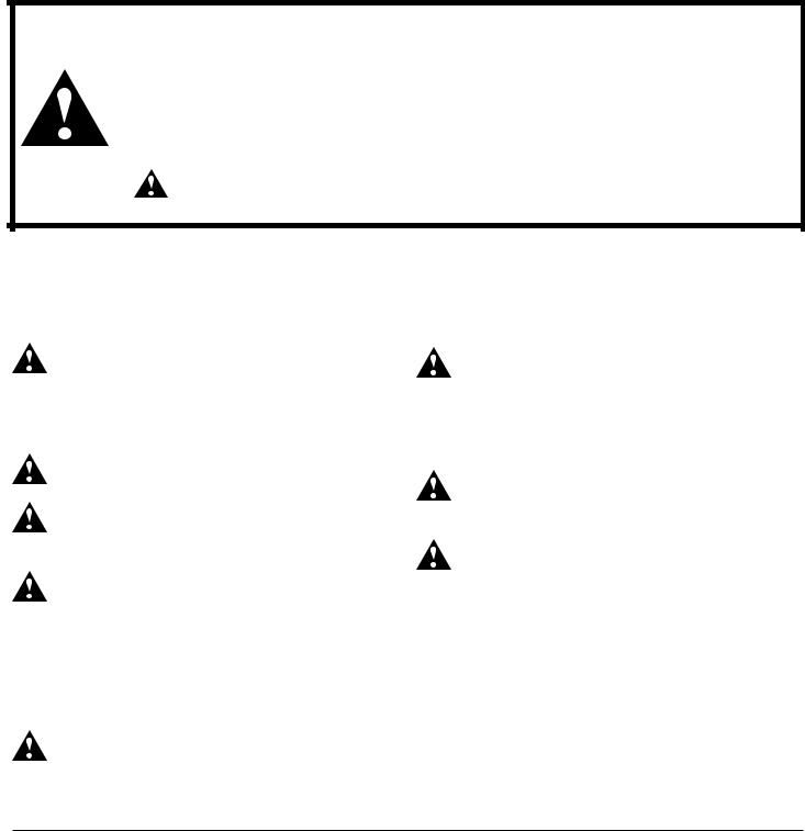
Warnings and Cautions
We provide many important safety messages in this manual about your Walk-In. Always read and obey all safety messages. This is the safety alert symbol.
This symbol alerts you to potential hazards that can kill, injure, or damage equipment.
All safety messages will follow the safety alert symbol and either the word “Warning” or “Caution.” These words mean:
WARNING You can be killed or seriously injured if you don’t follow instructions.
CAUTION Equipment can be damaged or destroyed if you don’t follow instructions.
Important Safety Instruction—Read Prior to Installation
All safety messages will tell you how to proceed to reduce the chance of death, injury, or damage to the Walk-In.
To reduce the risk of fire, electrical shock, injury, death, or damage when installing or repairing a Walk-In, follow basic precautions, including the following:
WARNING: During installation, make sure that equipment does not exceed floor rating. Note that floor
rating might be less than finished product rating until floor installation is complete (for example, until wear surface is field installed). Plywood sheeting should be used to spread the load.
WARNING: Remove children and unnecessary adults from the area when installing or servicing the Walk-In.
WARNING: Panel lifting methods and panel lifting equipment must meet OSHA approved guidelines for the
designed loads and lifting methods intended.
WARNING: Temporary support of panels during assembly is the responsibility of the general contractor
or the onsite installation contractor. Temporary support should only be attempted by trained individuals familiar with the safest methods possible for securing loose or otherwise unsupported panels. Stacking, leaning or blocking of panels when not permanently supported may result in hazardous conditions. Personnel injury or panel damage may result.
WARNING: Walking, climbing, or standing on nonpermanently supported panels may result in hazardous
conditions including falling. Personnel injury or panel damage may result.
WARNING: Improper wiring or lack of proper ground can result in fire, electrical shock, injury or death. Disconnect
power to the Walk-In before performing any electrical repairs. Field wiring or electrical repair should be done by a licensed professional electrician. Follow all local building codes and laws for electrical installation.
WARNING: In case of electrical fire, disconnect the power supply. Do not use water on electrical fires. Smother
the fire with an extinguisher rated for C-class fires.
CAUTION: Per NEC 300-7, all raceways passing from different temperatures shall be sealed with putty or other
method to stop the travel of moisture. Furthermore, all junction box cover plates shall be sealed. Verify these seals are in place and functioning properly after performing any service on the unit.
© Imperial Brown, Inc. 2015 |
3 |
|
Walk-In Coolers and Freezers |
Installation and Maintenance |
Important Things You Should Know
Shipping and Packaging
Upon receiving freight, check the bill of lading for the correct number of pallets and check the product for any shipping damage. Take photos of damaged goods. Report issues to both the trucking company
and Imperial Brown, Inc. Contact the freight company directly, at time of delivery, to file a claim.
Product Storage
If panels are to be stored for any length of time before installation, make sure that they are protected from moisture, sunlight, and temperature extremes. Exposure to sunlight or excessive temperature will make protective plastic sheeting difficult to remove and labels may dry out and peel off. Moisture trapped between panels can cause corrosion, such as white rust.
Permits and Engineering
Imperial Brown is not responsible for obtaining any permit, unless otherwise noted on the Sales Order.
Specific local building code, engineering, or regulatory requirements are to be communicated to Imperial Brown when placing the order.
Electrical Requirements
Electrical requirements for each electrical component are identified on the Shop Print. Component instructions and electrical wiring information for specific components is supplied along with each component. Component instructions may also be found online by searching for the component brand and model number.
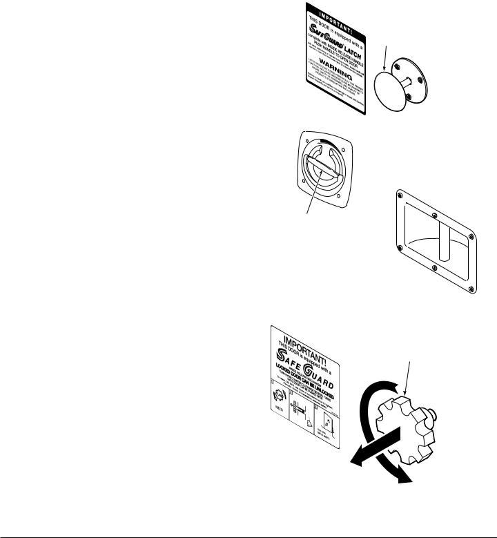
Inside Safety Release
Check to make sure the inside safety release on the door works correctly and that all personnel
understand how to use it.
Swing Doors—All swing doors equipped with a positive latch or lockable non-positive latch include an inside safety release mechanism. The safety release allows an occupant to open a latched or locked door from the inside. Push or turn the knob to release
the door. Follow the directions printed on the safety release label. This includes padlock hasps and full-
width removable locking bars.
Sliding Doors—All electrically-driven doors have a Manual Release mechanism that allows the manual operation of the door. This can be used by turning the inside release handle to disconnect the door from the drive. The door can then be slid open and close.
Sliding Door with Padlock Hasp—Sliding doors equipped with padlock hasp locking devices have an inside release knob. Turn the knob to unscrew the lock hasp system from the wall, in order to let the door open.
Push to
Open
473934
Swing Doors
Turn to Release Door.
Slide Door Open.
473933
Sliding Doors
Unscrew Knob. Pull Out.
Slide Door Open.
473935
Doors with padlock hasp or deadbolt locking device
4 |
© Imperial Brown, Inc. 2015 |
|

Walk-In Coolers and Freezers |
Installation and Maintenance |
Important Things You Should Know
Ceiling or Roof Loads
Each unit is designed to meet certain intended loads.
Specific load rating for each unit is indicated on the
Shop Print.
Live Loads—Limit number of workers on ceiling. Workers should be evenly spread out across the ceiling. Maintain perimeter loading in lieu of center (mid-span) loading whenever possible. Do not exceed
maximum loading (see Shop Print). Environmental Loads – Outdoor Walk-Ins are
designed for specific environmental loads like snow loads, wind loads, etc. Walk-In must be installed at its intended location or environmental load requirements
might not be met.
Equipment Loads—The Imperial Brown Design Department requires review of all equipment, including refrigeration, fire sprinkler, air handling, and others, before it is installed or attached to ceiling panels. Failure to submit a list of equipment for review will void any warranty and may lead to structure failure.
Installation Outside
Design Loads —These units are designed for wind load, snow load, and snow drift. Erecting another structure near the unit location may affect the load requirements, as loads and drifts may change.
Drainage – Make sure that rain drains away from the unit.
Installation Above Ground
Installing a unit above ground, such as on the second story of a building, always requires an insulated floor.
See Floor Installation.
Service Hot Line
800.238.4093
Construction Details
Tie-downs, hold-downs and other requirements must be installed or performed exactly as shown in the Shop Print, with no substitutions for fastener size, spacing or embedment. Variations require permission of the Imperial Brown Design Department.
Penetrations
Be aware that electrical or mechanical penetrations through the Walk-In may need to be addressed as the Walk-In is being erected, prior to losing access to these items.
Installation Over Fresh Concrete
Out-gassing from curing concrete may cause damage to the metal finish. To avoid, ensure proper ventilation
(i.e. an open door).
Installation Next To Existing Walls
Two inches of clearance is recommended for air flow and to allow for wall surface irregularity.
© Imperial Brown, Inc. 2015 |
5 |
|
Walk-In Coolers and Freezers |
Installation and Maintenance |
Getting Started |
|
Tools Required
Minimum required tool set includes:
• Tape measure |
• Construction hammer |
• Chalk line |
• Drill and electric screwdriver |
• Pry-bar |
• Carpenters bubble level |
• Caulking gun |
• Cam lock wrench (provided) |
• Tin snips |
|
Locate the Parts Box
The parts box(es) is generally a cardboard box located in one of the pallets. It contains this Installation Instruction, the Shop Prints of the Walk-In, a Shipping List, and supplies such as fasteners, cam lock wrench and caulk.
Shop Prints
Enclosed with the unit is a Shop Print showing proper location of all panels. Before placing any panel into position, check the print for proper location.
NOTE: This Installation Instruction Manual is provided to make the installation process as easy as possible, but it does not show every application available. Some illustrations and details may not apply to your unit. Please note any differences between the unit illustrated and your actual unit.
Make sure that you understand the prints, notes, and details in the Shop Prints (Parts Box) before beginning. See Table 1.
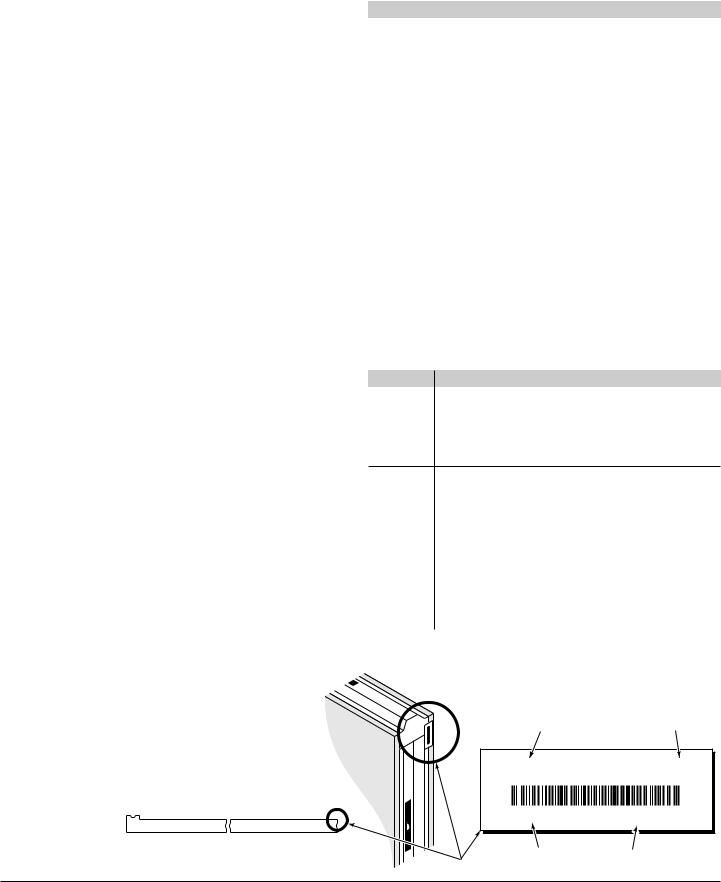
Identifying marks appear on all panels. These marks guide the installer to the proper location for each individual panel. See Figure 1 and Table 2.
Panels with the same part number (See Figure 1) can be interchanged.
Symbol |
Meaning |
|
|
AFF |
Above Floor Finish |
|
|
BKG |
Backing |
|
|
CL |
Centerline |
|
|
DC |
Double Cam |
|
|
DP |
Double Pin |
|
|
HIC |
Height In Clear (clear/finished opening height) |
|
|
ID |
Inside Dimension |
|
|
MCA |
Maximum Current Amperage |
|
|
MOPD |
Maximum Overage Protection Device (Circuit Breaker) |
|
|
NBI |
Not By Imperial Brown |
|
|
NIC |
Not In Contract |
|
|
NTS |
Not To Scale |
|
|
O/C |
On Center |
|
|
OD |
Outside Dimension |
|
|
RC |
Reverse Cam |
|
|
SIM. |
Similar |
|
|
SPL |
Special (panel has special features or |
|
|
non-standard cam/pin layout) |
|||
|
|||
TYP |
Typical |
|
|
WIC |
Width In Clear (clear/finished opening width) |
|
|
Table |
1. Common Drawing Abbreviations on Shop Print |
|
|
|
|
|
|
Symbol |
Meaning |
||
W1 |
Wall panel #1 |
|
|
C1 |
Ceiling panel #1 |
|
|
F1 |
Floor panel #1 |
|
|
S1 |
Screed panel #1 |
|
|
U1 |
Floor Spline #1 |
|
|
[A]Door or opening [A]
V1.A |
Valance #1 above opening [A] |
|
A valance panel goes above a window or an opening. |
|
Valance layout is best shown on elevation views. |
B1.A |
Base #1 below opening [A] |
|
A base panel goes below a window or an opening. Base |
|
layout is best shown on elevation views. |
T |
Thermometer |
$ |
Single-pole switch |
$3 |
3-way switch |
$4 |
4-way switch |
|
Table 2. Sample Panel Numbers |
W1 W2
40 47
01-46546 |
W2 |
|
A |
Panel |
Part |
Number |
Number |
W2 A
46546-01 4" x 47" x 96"
Int. SS04 / Ext. SS04 (NSF Foam Gasket)
|
|
473902 |
Label |
Short Job |
Description |
Number |
Figure 1. Panel Label |
6 |
© Imperial Brown, Inc. 2015 |
|

Walk-In Coolers and Freezers |
Installation and Maintenance |
Shipping List
The Shipping List included in the Parts Box identifies every item shipped and indicates in what parcel (pallet or box) it is located. It also indicates if a parcel is located in another parcel (for example, the Parts Box being in a pallet).
Panels are stacked in the best way possible to minimize the risk of shipment damage. They are not stacked in order of panel numbers. Use the Shipping List to easily locate panels and hardware.
Cam Lock Fasteners |
|
|
|
|
|
|
Panels are joined, using a 3/8” hex wrench (supplied) |
|
|
||||
on a cam lock device. Imperial Brown cam lock |
|
|
||||
fasteners must be fully understood before assembling |
|
|
||||
prefabricated panels. All cam locks must be in the |
|
|
||||
Open position before placing |
Cam Lock |
|
Panel |
|||
panels together. Fasten the cam |
|
|||||
Hook |
Gaskets |
|||||
locks as follows: |
|
|
|
|
|
|
|
|
|
|
|
|
|
1. With the cam locks of the first |
|
|
|
|
|
Panel |
panel in the fully Open position, |
|
|
|
|
|
|
|
|
|
|
|
|
|
Panel |
|
|
|
|
||
place the second panel |
|
|
473918 |
|||
|
|
|||||
Hex Wrench |
||||||
into position. |
|
|
|
|
|
|
It should be tight along the matig |
Figure 2. Open Position |
|
|
surface and flush at the edges. See |
|
Figure 2. |
|
2.Turn the cam lock clockwise 1/4 turn until the lock is engaged with the hinging pin. Do not tighten yet.
See Figure 3.
3.Check that the panels are still tight and properly aligned, then turn the cam lock 1/2 turn to the fully locked position. This will draw the panels tightly together. Install cam hole covers. See Figure 4.
1/4 Turn
Cam Lock

 Hook
Hook
Hinging Pin |
473919 |
|
|
Figure 3. Engaged Position |
|
Compressed |
1/2 Turn |
Gaskets |
to |
|
Fully |
|
Locked |
473920
Figure 4. Locked Position
Inside Surface
of Panel
Inside Surface
of Panel
473905
Hinging Pin
Figure 5. Cam Lock Fastener
© Imperial Brown, Inc. 2015 |
7 |
|
Walk-In Coolers and Freezers |
Installation and Maintenance |
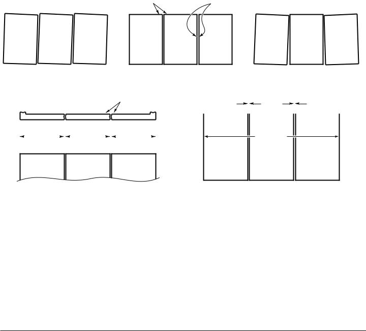
Assembling Panels Together
Panel widths are shown along each panel on the
plan views. See the Shop Print. Standard joint width is 1/16” between panels. This width may be different for certain special joint types. Verify actual joint size on the Shop Print. When fastening panels together, be certain that dimensions are respected. For example, irregular or loose tightening of the cam locks may cause overall wall width to increase. See Figure 6.
Proper Alignment |
Flush |
Parallel |
No |
Yes |
No |
Proper Joint Size |
|
|
Flush |
⁄" Joint |
|
|
|
⁄" Joint |
||||||||||||||||
|
|
|
||||||||||||||||||||||
|
|
|
|
|
|
|
|
|
|
|
|
|
|
|
|
|
|
|
|
|
||||
|
|
|
40" |
|
|
|
|
|
40" |
|
|
|
|
|
40" |
|
|
= |
|
|
|
|
|
|
|
|
|
|
|
|
|
|
|
|
|
|
|
|
|
|
|
|
|
|
|
||||
|
|
|
|
|
|
|
|
|
|
|
|
|
|
|
|
120 " |
||||||||
|
|
|
|
|
|
|
|
|
|
|
|
|
|
|
|
|
||||||||
|
|
|
|
|
|
|
|
|
||||||||||||||||
|
|
Panel |
|
|
Panel |
|
|
Panel |
|
|
Overall |
|||||||||||||
473903
Figure 6. Assembling Panels
8 |
© Imperial Brown, Inc. 2015 |
|
 Loading...