

Page 1

Varipole Support System
INSTRUCTIONS
Page 2
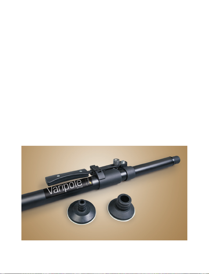
Thank you for choosing the Impact Varipole Support System. The
adjustable Varipole easily and quickly mounts between solid oors and
ceilings, giving you a stable support system for backgrounds, reectors,
lights, or grip accessories. It was designed with a unique tension
mechanism and locking system that exerts sufcient pressure to securely
wedge the Varipole’s protective rubber ends between ceiling and oor.
To ensure your personal safety and the safety of your equipment, please
read these instructions carefully on how to set up and use this equipment.
We trust that our Varipole Support System will serve your creative
inspirations reliably for years to come.
Each Varipole package should include the following:
• Varipole support pole
• Top rubber cushion
• Bot tom rubber cushion
All images in this manual are for ill ustrative purposes only.
Your Varipole system may differ slightly from the one pictured.
2
Page 3
Caution
Safe operation of the Varipole requires that it be tted between two rigid suppor t
surfaces. Make certain that you are engaging a solid ceiling and not pressing against
unsupported ceiling panels . If you do not have a secure ceiling to engage, use a
Varipole base.
Make cer tain that t he handle is locked and the entire set-up is stable before proceeding.
Verify that your se t-up is s table each time after attaching or removing ligh ts, paper
drives, or any other i tems.
The Varipoles are not air-cushioned. Make certain that the poles are locked properly in
place before attaching x tures or backgrounds. And make sure you remove all
accessories and backgrounds before dismantling the Varipoles.
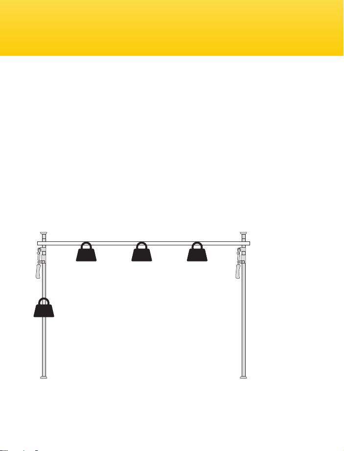
Do not exceed the following maximum load limi ts: Do not load any single Varipole with
more than 55 lbs (25 kg). Do not load a cros sbar wi th more weight than is shown in t he
diagram below.
44lbs 33lbs
6-foot
crossbar
55lbs
no crossbar
Do not operate the Varipole below -20 °F (-30 °C) or above 14 0°F (6 0°C). Keep t he Varipole
dry. Dry thoroughly if the unit ge ts wet. Avoid salt water. Use only mild detergent and a
sof t cloth to clean t he Varipole.
9-foot
crossbar
24lbs
12-foot
crossbar
3
Page 4

Setting Up Your Varipole
1
The Varipole is packed with it s rubber
cushions removed. Insert the cushion
wit h the wide tube into the bot tom of t he
Varipole and push rmly.
3
Place the Varipole in the desired location.
Make cer tain that you have a r m
foundation below and a solid ceiling
above.
4
2
The cushion with the narrow tube insert s
into the top of the Varipole. F irmly push
the cushion into the Varipole until i t is
mounted securely.
4
Press the locking latch out ward to
release the height adjustment handle.
Page 5

5
Lift the height adjust ment handle. W ith
one hand stabilizing the lower tube, lift
the upper tube until i t engages the ceiling.
6
Making cert ain that the Varipole is
verticall y level, bring the handle back
down until i t clicks into its locking latch.
7
Make cer tain that your installation is
secure by gently rocking the pole.
8
Recheck t he stability of your setup after
loading or removing attachments.
5
Page 6

Adjusting Tension
1
The tension that the handle delivers to the
upper tube is adjustable. Release the
handle’s locking latch and swing the
handle outwards.
3
Slide t he tension knob to the lower (more
tension) or upper (less tension) position
on the handle bracket. Retighten the
tension knob and return the handle to i ts
locked position.
6
2
Unscrew the tension knob on the handle
bracket.
4
If the upper tube slips under the stress of
your installation, use a socket wrench to
tighten the nut at the top of t he handle
bracket.
Page 7

Varipole Extenders
1
If your Varipole at its full ex tension will
not reach the ceiling, a Varipole E xtender
can be used.
3
Inser t the narrow end of the Varipole
Ex tender into t he top of the Varipole.
2
Remove the cushion and the springloaded t ube from the top of the Varipole.
4
Inser t the spring-loaded tube and cushion
into the top of the Varipole E xtender.
Follow the instructions listed previously
for setting up your Varipole.
7
Page 8

One-Year Limited Warranty
This IMPACT product is warranted to the original purchaser to be free from
defects in materials and workmanship under normal consumer use for a period of
one (1) year from the original purchase date or thirty (30) days after replacement,
whichever occurs later. The warranty provider’s responsibility with respect
to this limited warranty shall be limited solely to repair or replacement, at the
provider’s discretion, of any product that fails during normal use of this product in
its intended manner and in its intended environment. Inoperability of the product
or part(s) shall be determined by the warranty provider. If the product has been
discontinued, the warranty provider reserves the right to replace it with a model
of equivalent quality and function.
This warranty does not cover damage or defect caused by misuse, neglect,
accident, alteration, abuse, improper installation or maintenance. EXCEPT AS
PROVIDED HEREIN, THE WARRANTY PROVIDER MAKES NEITHER ANY EXPRESS
WARRANTIES NOR ANY IMPLIED WARRANTIES, INCLUDING BUT NOT LIMITED
TO ANY IMPLIED WARRANTY OF MERCHANTABILITY OR FITNESS FOR A
PARTICULAR PURPOSE. This warranty provides you with specic legal rights, and
you may also have additional rights that vary from state to state.
To obtain warranty coverage, contact the Impact Customer Service Department
to obtain a return merchandise authorization (“RMA”) number, and return the
defective product to Impact along with the RMA number and proof of purchase.
Shipment of the defective product is at the purchaser’s own risk and expense.
For more information or to arrange service, visit www.impactstudiolighting.com
or call Customer Service at 212-594-2353.
Product warranty provided by the Gradus Group.
www.gradusgroup.com
IMPACT is a registered trademark of the Gradus Group.
© 2014 Gradus Group LLC. All Rights Reserved.
GG2
 Loading...