

Page 1
MANUAL,
PORTABLE,
(VENTILATOR,
UNI-VENT™
700
MODEL
SERIES
754/754M
OPERATION
SELF-CONTAINED
COMPRESSOR,
Eagle™
&
VENTILATION
AIR/OXYGEN
SERVICE
SYSTEM
MIXER)
Impact
27
West
©
1997
P/N
Instrumentation,
Fairfield
Caldwell,
Impact
906-0754-02
Place
Instrumentation,
New
Jersey
Inc.
Inc.
07006
REV.
1.85C
(03/00)
Page 2
TABLE
LIST
OF
CONVENTIONS,
ABBREVIATIONS
A
WORD
SHIPPING
ACCESSORIES
LIMITED
CALIBRATION/PREVENTATIVE
UNPACKING
LOCATION
WARNINGS
ASSEMBLY,
OF
ILLUSTRATIONS
ABOUT
CONTENTS
LIST
COPYRIGHT
OF
USE
AND
INTERCONNECTIONS
CONTENTS
SUBJECT
TERMINOLOGY,
AS
EAGLES
CAUTIONS
USED
RELEASE
DEFINITIONS
IN
THIS
MANUAL
(MODEL
MAINTENANCE
REGARDING
AND
754M
USE
INITIAL
AND
only)
NOTICE
ADJUSTMENTS
PAGE
vi
vii
vii
vii
vili
viti
viii
viii
SECTION
INTRODUCTION
FEATURES
DESCRIPTION
CONTROLS
EXTERNAL
OFF/ON-set
PRESSURE
LOW
INSPIRATION
AIR/OXYGEN
MANUAL
LCD
STATUS
I.
OPERATION
OF
CONTROLS,
AIR
OFF/ON
Switch - PRESSURE
ALARM/PEAK
PRESSURE
BREATH/TRIGGER
VISUAL
MODE - V
CENTER - PEAK
DIGITAL
SETPOINTS - P.y - EXTERNAL
PLATEAU - HIGH
AIRWAY
TIME/L:E
BAR
PRESSURE
RATIO - TIDAL
ALARM
TIME/T:E
MIXER
INDICATORS
min - INSPIRATION/EXHALATION
AIRWAY
GRAPH - HIGH
AIRWAY
VISUAL
Switch - SIGH
INSPIRATORY
Control - VENTILATION
RATIO
Control - ALARM
Switch - MODE
PRESSURE - MEAN
PRESSURE
ALARM
(setpoint) - RATE - INSPIRATION
VOLUME - FIO,
INDICATORS
PLATEAU
Control - TIDAL
and
LOW
AIR - SIGH - PEEP - PRESSURE
OFF/ON
MUTE/CANCEL
AIRWAY
ALARM
Switch - PEEP
OFF/ON
PRESSURE
RATE
VOLUME
SELECTOR
-
POWER
AIRWAY
PRESSURE
(setpoint) - LOW
AND
CONNECTIONS
Switch - HIGH
RELIEF
Control
INFORMATION
Control
Control
Switch
Switch
PRESSURE
ALARM
-
-
-
-
-
-
Page 3
TABLE
LED
VISUAL
STATUS
CHARGE
ALARM
ALARM
SYSTEM
LCD
VISUAL
ALARMS - OPERATING
BATTERY
DISCONNECT - HIGH
LOW/FAIL - EXT
SETTINGS - Vy - COMPRESSOR
ALARMS - NON-OPERATING
INVERSE
SYSTEM
OF
INDICATORS
FAILURE
INDICATORS
LOW - EXTERNAL POWER
I:E - TRANSDUCER
FAILURE - VENTILATOR
CONTENTS,
SUBJECT
AIR
(cont'd)
LOW - LOW
PRESSURE - APNEA - HIGH
LOW/FAIL - FIO) - PRESSURE
CALIBRATION
FAILURE
ABORT
PRESSURE
PEEP - ©,
ALARM
-
PAGE
17
-
ALARMS - ADVISORY
INSPIRATION
Vy
SETTINGS - PREVENTATIVE
EXTENDED
TOTAL
CONNECTIONS
OXYGEN
EXHALATION
COMMUNICATIONS
OPERATING
INITIAL
INITIAL
SELF-CHECK
TRANSDUCER
USER
SET-UP,
SET-UP
AUTOMATIC
MANUAL
PROGRAMS
TIME
NON-USE/STORAGE
FLOW
BACKUP
INLET - AIR
VALVE - EXTERNAL
POWER
SELF-CHECK
CALIBRATION
CALIBRATION
CALIBRATION
TRUNCATED
INLET - GAS
PORT
SELECTION & STOPPING
TO
3-SEC - PLATEAU
MAINTENANCE
-
EXTERNAL POWER
OUTLET - TRANSDUCER
POWER
AND
TRANSDUCER
(AUTO
CAL)
-
JACK
-
CALIBRATION
VOLUME
FAILURE
-
-
-
sie
Page 4
TABLE
MODES
ASSIST-CONTROL
SYNCHRONIZED
CONTINUOUS
CONTROL
USING
USING
BACKUP
HUMIDIFIERS
OPERATOR
ALARM
OPERATING
OF
OPERATION
VENTILATION
POSITIVE
PRESSURE
VENTILATOR
PERFORMANCE
FUNCTIONS
OF
AND
ALARMS
CONTENTS,
SUBJECT
VENTILATION
INTERMITTENT
POSITIVE
END
PLATEAU
HEAT
PRESSURE
DURING
EXPIRATORY
MOISTURE
CHECKS
(cont'd)
(ACV)
MANDATORY
VENTILATION
APNEA
PRESSURE
EXCHANGERS
VENTILATION
(CPAP)
(PEEP)
(HME'S)
(SIMV)
PAGE
4-1
42
43
4-5
4-5
4-6
4-6
47
4-7
4-7
5-1
5-1
BATTERY
LOW
PEEP - O,
ALARM
NON-OPERATING
INVERSE
SYSTEM
ADVISORY
INSPIRATION
VT
SETTINGS - PREVENTATIVE
EXTENDED
TOTAL
ALARM
LOW - EXTERNAL
PRESSURE - DISCONNECT - HIGH
LOW/FAIL - EXT
SETTINGS - V; - COMPRESSOR
ALARMS
I:E - TRANSDUCER
FAILURE - VENTILATOR
ALARMS
TIME
NON-USE/STORAGE
FLOW
MUTING
BACK
AND
POWER
AIR
CALIBRATION
TRUNCATED
UP
CANCELLING
LOW
-
PRESSURE - APNEA - HIGH
LOW/FAIL - FIO; - PRESSURE
FAIL
TO
3-SEC - PLATEAU
MAINTENANCE
-
EXTERNAL
ABORT
-
POWER
-
VOLUME
FAILURE
54
5-6
-
-
5-7
-iii-
Page 5

TABLE
ROUTINE
PREVENTATIVE
CALIBRATION
CLEANING
PRESSURE
COMPRESSOR
PREVENTATIVE
BATTERY
IN
CASE
OPERATOR
OPERATOR
STORAGE
SPECIFICATIONS.
CARE:
HOSE
CARE
OF
DIFFICULTY
CORRECTABLE
PROBLEMS
INFORMATION
OF
CONTENTS,
SUBJECT
CALIBRATION,
MAINTENANCE
INLET
MAINTENANCE
AND
RECHARGING
FILTER
PROBLEMS
REQUIRING
CLEANING
SERVICE
(cont'd)
PAGE
AND
6-1
6-1
6-1
6-1
6-1
6-1
7-1
8-1
8-1
8-1
9-1
10-1
LIMITED
LIST
WARRANTY
OF
ILLUSTRATIONS
FIGURE
1
2
3
4
5a Initial
Sb
Model
Interconnection
Control
Disposable
Setup
Initial
Setup
DESCRIPTION
754/754M
Diagram
Panel
Ventilator
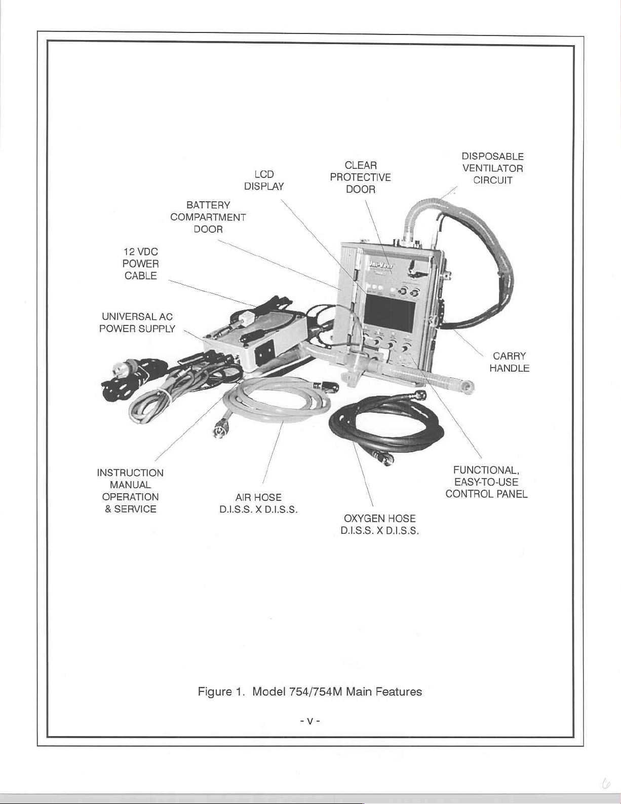
Main
Features
Circuit
11-1
PAGE
v
x
1-2
1-11
3-1
3-2
-iv-
Page 6
12
VDC
POWER
CABLE
UNIVERSAL
POWER
AC
SUPPLY
LCD
DISPLAY
BATTERY
COMPARTMENT
DOOR
m
P
=
X
、
CLEAR
PROTECTIVE
DOOR
\
DISPOSABLE
VENTILATOR
CIRCUIT
CARRY
HANDLE
INSTRUCTION
MANUAL
OPERATION
&
SERVICE
Figure
HOSE
AIR
DIS.S.XDIS.S.
1.
Model
754/754M
-V-
\
\
OXYGEN
DIS.S.XDIS.S.
Main
HOSE
Features
\
FUNCTIONAL,
EASY-TO-USE
CONTROL
PANEL
Page 7
CONVENTIONS,
ABBREVIATIONS
CONVENTIONS
[
WARNING
[ A WARNING
[
CAUTION
[ A CAUTION
[NOTE
[
Information
TERMINOLOGY
Air/Oxygen
Model
754/754M - Uni-Vent™
Pressure
Uni-Vent™ - Model
Ventilator-Compressor-Air/Oxygen
message
statement
immediately
Mixer - Blender,
Plateau - Plateau
TERMINOLOGY,
AS
identifies
identifies
following
Gas
754/754M,
Ventilator,
USED
conditions
conditions
Blender
IN
THIS
that
could
have
that
could
is
of
sufficient
Mixer - Ventilator
importance
Eagle™
DEFINITIONS
MANUAL
an
damage
adverse
this
that
effect
device.
emphasis
upon
is
AND
the
made.
patient
or
operator.
DEFINITIONS
Gas - Air
Ventilator - Any
# - Denotes
ABBREVIATIONS
Airway
Alarm
Assist-Control - A/C
Assist-Control
Breaths
Centimeters
Continuous
delivered - del
End
Fraction
Light
Liquid
liters - L
Liters
milliliters - ml
Oxygen - O,
Peak
Positive
Pounds
Power
Synchronized
Tidal
Work-of-Breathing - WOB
or
oxygen
that
Pressure - Paw
Message
Ventilation(s) - ACV
Per
Minute - BPM
of
Water - cmH,O
Positive
Tidal
Carbon
of
Inspired
Emitting
Crystal
Per
Inspiratory
Information
Volume - V
Diode - LED
Display - LCD
Minute - LPM
End
Expiratory
Per
Square
Intermittent
or
the
resultant
reference
display
Center - AMC
Dioxide - ETCO,
Pressure - PIP
to
the
will
indicate
Airway
Oxygen - FIO,
Inch - PSI
Center - PIC
Pressure - CPAP
Pressure - PEEP
Mandatory
Model
mixture
of
these
two
754/754M,
some
number
Ventilation(s) - SIMV
Uni-Vent™,
between 0 an 9 for
gases
-vi-
Ventilator-Compressor-Air/
each
appearance
of
Page 8
A
WORD
This
very
ventilators.
contained
never
before
sees
a
future
ABOUT
special
Uni-Vent™
Where
portable
found
that
no
EAGLES
the
eagle
has
ventilator
in
other
a
portable
portable
available
was
named
come
ventilator
ventilator
Eagle™,
to
symbolize
today.
Where
this
small.
has
to
represent
power
the
ever
seen.
And
-
this
eagle
where
The
its
leadership
Eagle™
is
known
the
eagle
Uni-Vent™
role
in
the
represents
for
its
is
skills
known
Eagle™
the
-
for
-
world
most
this
its
its
not
Eagle™
keen
of
portable
powerful,
just
possesses
sight
-
another
self-
this
bird!
skills
Eagle™
SHIPPING
Each
Uni-Vent™
lea.
lea.
lea.
lea.
lea.
Tea.
lea.
lea.
Each
Uni-Vent™
lea.
lea.
lea.
lea.
lea.
1
ea.
lea.
2
ea.
2ea. | Instruction
ACCESSORIES
The
Accessories
Accessories
quantity
may
required.
CONTENTS
Ventilator,
Ventilator
High
High
Universal
Universal
12
Operator's
Ventilator,
Ventilator
High
High
Universal
12
Case,
Strap,
List
be
ordered
Circuit,
Pressure
Pressure
AC
AC
VDC
Power
Circuit,
Pressure
Pressure
AC
VDC
Power
Padded,
Velcro®,
LIST
contains
Manual,
direct
Eagle™
Compressor,
Eagle™
Compressor,
Manual,
common
Model
Disposable,
Hose,
D.LS.S.
Hose,
D.1.S.S.
Power
Supply
Power
Supply
Cable
Model
Model
Disposable,
Hose,
D.I.S.S.
Hose,
D.I.S.S.
Power
Supply
Cable
Ventilator & Accessories
24"
Long
Operation
items,
from
754
Air/Oxygen
Single
Oxygen X D.LS.S.
Air X D.LS.S.
(standard)
with
754/754M.
754M
Air/Oxygen
Single
Oxygen X D.I.S.S.
Air X D.LS.S.
with
& Service
required
Impact.
When
is
16-30V
16-30V
shipped
Mixer
Patient
Air,
DC-DC
is
shipped
Mixer
Patient
Air,
DC-DC
(Model
from
time
ordering,
with
the
Use
Oxygen,
6'
Long
Converter
with
Use
Oxygen,
6'
Long
Converter
754M)
to
time.
please
following
6'
Long
(optional)
the
following
6'
Long
Each
item
include
the
components:
components:
is
preceded
part
number,
by
its
part
number.
description
and
Send
written
PART
334-0020-00
402-0014-00
402-0016-00
820-0067-00
825-0002-00
825-0004-00
703-0754-09
703-0754-08
703-0754-03
906-0754-01
906-0754-02
purchase
NUMBER
orders
to:
Impact
P.O.
West
Telephonic
Fax
Strap,
Velcro®,
Case,
Padded,
Case,
Padded,
Ventilator
High
High
Universal
Universal
12
Operator's
Instruction
Pressure
Pressure
VDC
Circuit,
AC
AC
Power
Manual
Manual,
Instrumentation,
Box
508
Caldwell,
orders:
24"
Ventilator & Accessories
Ventilator
Hose,
Hose,
Power
Power
Cable
New
orders:
DESCRIPTION
Long
Disposable,
D.I.S.S.
D.I.S.S.
Supply
Supply
(Model
Operation & Service
>
vii
-
Inc.
Jersey
Single
Oxygen X D.I.S.S.
Air X D.I.S.S.
with
16-30V
754/754M)
07007-0508
973/882-1212
973/882-4993
Patient
Use
Oxygen,
Air,
6'
DC-DC
(754M)
6'
Long
Converter
Long
Page 9
LIMITED
Permission
for
use
in
COPYRIGHT
is
hereby
a
military
granted
service
to
the
training
Department
program
CALIBRATION/PREVENTATIVE
This
device
should
be
operating
year
calibration
sensitive
next
should
maintenance
754/754M
Alarm
specifications
unless
significant
check
Calibration
calibration
be
examined,
contains
messages
should
is
due.
checks
internal
will
incorporated
(see
usage
be
made
label
is
DO
NOT
operationally
can
be
found
appear
into
LIMITED
warrants
following
attached
remove
tested,
in
clocks
that
in
the
Alarm
a
to
the
UNPACKING
Compare
shipping
before
LOCATION
shipping
damage.
attempting
case
contents
If
there
is
operation.
OF
USE
against
no
apparent
RELEASE
of
and
other
a
regular
WARRANTY
shorter
the
and
SERVICE
monitor
Message
SHIPPING
sign
each
outer
this
label.
its
of
preventative
period
2000
batteries
cumulative
mechanical
(Model
Defense
to
technical
MAINTENANCE
statement).
between
hours
case,
Following
section
Center
CONTENTS
of
indicating
recharged
of
the
use
when
damage,
754M
reproduce
training
only)
all
material
programs.
furnished
NOTICE
maintenance
Calibration
preventative
cumulative
when
6-months
Model
and
storage/non-use
calibration/preventative
list.
the
of
before
754M
Examine
read
instructions
program
maintenance
use
last
continuous
patient-use
to
measurements
or
12-month
calibration
Instruction
periods.
instrument
under
this
insure
compliance
should
inspections.
period.
was
storage/non-use,
is
attempted.
Manual.
Appropriate
maintenance
for
contained
be
A
A
pressure-
performed
Recommended
The
is
any
obvious
within
contract
with
made
each
complete
and
the
this
device
Model
Advisory
required.
signs
this
Manual
of
The
Uni-Vent™
operated
barrier
in a wet
(small
WARNINGS
[
WARNING:
[
WARNING:
[
WARNING/CAUTION:
WARNING/CAUTION:
port
(see
[
CAUTION:
[
WARNINGS
CAUTION:
SECTION
CAUTION:
entitled
[
CAUTION:
CLEANING
Eagle™,
tarp,
Electric
Do
Figure
2).
Federal
AND
Service
entitled
Do
not
Internal
Model
environment,
plastic
sheet,
AND
not
CAUTIONS
SERVICE).
allow
CAUTIONS
shock
hazard,
operate
law
is
for
components
this
Possible
DO
NOT
restricts
to
be
performed
oil
additional
754/754M,
users
should
etc.).
do
instrument
explosion
block
this
device
REGARDING
and
grease
instructions.
are
susceptible
is a transportable
take
precautions
REGARDING
not
remove
or
connect
by
qualified
to
enter
equipment
prior
to
hazard
to
sale
USE,
system.
to
if
the
by
damage
device,
and protect
covers.
reading
biomedical
instructions
used
in
the
ventilator
or
on
the
(cont'd)
See
ROUTINE
from
therefore,
this
USE
contained
presence
circuit
hose
order
of a physician.
equipment
CARE
static
discharge.
its
location
device
by
within
of
flammable
to
the
Internal
technicians
AND
of
use
will
covering
only
MAINTENANCE
it
with a protective
this
Manual.
anesthetics.
Compressor
(for
Model
vary.
Air
754M,
section
When
Filter
see
-
vili
-
Page 10
ASSEMBLY,
ASSEMBLY:
Model
754
Model
754M
check
your
RECHARGING
INTERCONNECTIONS:
CAUTION:
NOTE:
440
Hz.
Model
includes a 16-30V
the
secondary
The
black
NOTE:
the
11-15
negative
Follow
©
1.
a
50-PSI
e
2.
external
©
3.
connectors
disposable
+
4.
JACK
The
standard
Voltage
754M),
is
input
input
For
11-15
VDC
ground.
Foruse
For
Connect a disposable
Connect
operable
lead
power
INTERCONNECTIONS
-
No
assembly
-
Depending
contract
section
interconnection
with
external
use with
air
source.
on
the
ventilator
Universal
and
external
Universal
and
line
freguency
from
DC-DC
VDC
Converter.
leads
provided.
is
positive,
operation,
source. A 12
is
required
upon
accordingly.
for
instructions.
instructions
external
external
oxygen:
oxygen
Model
source,
air:
Use
only
ventilator
754/754M
circuit
AC
Power
power
source
AC
Power
sensing
115/230
It
Attachment
white
is
connect
VDC
before
contract
(see
VAC,
accepts
negative.
requirements,
If
battery
prior
connect
Use
only
connect
medical-grade
Supply
Power
high
circuit
Connector
Figure
Supply,
(see
Figure
is
is
automatic.
50
to
external
to a mating
Do
an
appropriate
Cable
AND
placing
pack
4).
operable
400
this
installation
to
placing
high
pressure
medical-grade
pressure
compressed
to
its
respective
Panel.
or
12
VDC
5b).
from
An
optional
Hz
(voltage
DC
voltages
connector
not
attach
power
is
provided
INITIAL
device
battery
pack
is
required,
this
device
oxygen
air
hose
air
gas
Observe
Power
AC
Universal
and
ranging
is
the
braided
cord
between
for
attachment
into
operation
installation
into
hose
oxygen
between
(see
Figures
outlet,
directions
Cable,
voltages
line
frequency
from
required
shield.
EXTERNAL
ADJUSTMENTS
may
see
BATTERY
service
between
(see
Figures
AIR
transducer,
between
between
AC
Power
16
and
to
an
be
(see
Figure
OXYGEN
5a
inlet
port
Sa
and
5b).
and
included
EXTERNAL
90
and 265
Supply
sensing
to
30
volts
polarity
must
POWER
automotive
necessary.
CARE
2).
and
5b).
and
exhalation
with
(standard
is
automatic),
which
be
power
Please
AND
inlet
port
a
50-PSI
each
POWER
volts,
47
connect
observed.
JACK
source,
and
valve
to
with
and
to
and
INITIAL
Before
VISUAL
patient
ADJUSTMENTS:
placing
use.
this
INDICATORS
device
into
operation,
AND
CONNECTIONS.
read
section
Make
entitled
OPERATION:
control
settings
DESCRIPTION
and verify
device
OF
CONTROLS,
performance
prior
to
Page 11
uNiversaL
AC
POWER
SUPPLY
CONNECTOR
EXTERNAL
AIR
INLET
FITTING
MALEDISS.
.-
3
GAS
OUTLET
HOSE
CONNECTOR
\
EXTERNAL
OXYGEN
FITTING
MALE
D.LS.S.
/
INLET
“VALVE
TRANSDUCER
HOSE
_>
EXHALATION
HOSE
BARB
(REAR)
BARB
(FRONT)
DISPOSABLE
VENTILATOR
CIRCUIT
INTERNAL
COMPRESSOR
AIR
FILTER
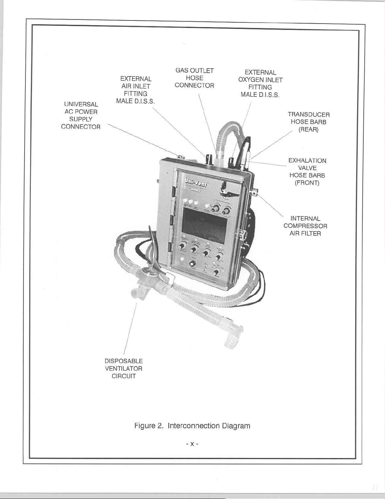
Figure
2.
Interconnection
“Ke
Diagram
Page 12

SECTION
I.
NTRODUCTION
User's
will
find
this
instrument
device
features. A complete
many
features.
Your
Model
754/754M
controlled
settings,
are
Plateau.
ventilatory
control
The
blended
and
filtered.
to
internal
Uni-Vent™
may
12
265
directly
permits
provided.
positive,
operating
by
alarm
operable
All
limits
Model
from
external
Acceptable
componentry.
be
recharged
VDC
Power
volts,
47
to
AC
use
Attachment
the
power
an
internal
parameters,
with
or
modes
are
backup
assures
peak
inspiratory
754/754M
external
compressed
is
operable
within
Cable
to
440
mains
from
external
white
is
- all
without
input
Hz.
providing
negative.
gas
OPERATION
quite
easy-to-learn
understanding
is a portable,
microprocessor
gas
source(s),
PEEP,
with
PEEP
and
altitude
continued
can
provide
oxygen
air.
External
gas
It
is
from
the
range
is
provided.
An
optional
DC
to a mating
is
dedicated
mechanical
pressures
gas
(compressed
pressures
operable
internal,
of
either
The
Universal
115/230
voltages,
connector
Do
not
for
and
of
its
capabilities
electronically
(CPU)
gas
or
without
compensable
and
high
mixtures
gas
compressed
may
in
any
rechargeable
of
Universal
volts,
ranging
attach
patient
controlled
which
flows,
gas
SIGH.
support
pressure alarm
with
cylinder
air,
range
up
position;
the
aforementioned
AC
AC
Power
50
to
400
from
is
required
the
braided
care.
operate.
continuously
blends, and
to
oxygen
or
delivered
to
upright,
batteries;
Power
16
and
and
ACV
minimize
if
the
content
PTLOX)
80-PSI
Supply
Supply
Hz
(voltage
to
30
volts
polarity
shield.
The
ventilator,
patient
on
11-15
following
limitations
monitors
power
and
SIMV
your
becomes
setpoint.
ranging
and
from
an
without
its
side,
volts
DC
voltages. A Universal
connects
(standard
and
which
must
The
Model
text
will
compressor,
and
signals.
are
operable
patient's
apneic.
from
internal
electric
effecting
or
lying
DC
(negative
directly
with
line
frequency
connect
be
observed.
754/754M
presents a brief
allow you
displays
ACV,
work-of-
21
compressor,
compressor,
measurement
flat.
the
to
to
take
air/oxygen
airway
SIMV
with
or
breathing
An
adjustable
to
100%. Gases
or
must
ground).
AC
to
AC
mains
Model
754M)
sensing
the
secondary
The
black
does
not
overview
advantage
mixer.
pressure,
and
CPAP
without
external
accuracy
is
consume
Pressure
and
pressure
may
oxygen
be
oil-less
Its
battery
Power
Supply
providing
connects
automatic),
input
leads
input
lead
of
of
its
It
is
control
modes
automatic
limit
be
and
or
danger
pack
and
90
to
and
is
gas
for
Your
ventilatory
Advisory
operating,
The
polycarbonate
aeromedical,
transport,
or
Model
deployment
754/754M
homecare,
FEATURES
Microprocessor
‧
power
Extensive
©
«
Contemporary
‧
©
©
‧
e
system
employs a comprehensive
section
(see
extremely
is
is
material.
Gas-efficient
on
gas
Rechargeable
Self-contained
It
prehospital
and
and
storage.
sources,
alarm
electronic
for
operating
batteries,
entitled
durable
appropriate
control
internal
design
system,
of
compressor
monitoring
facilitate
to
control
power.
fully
may
ALARM
and
use
for
ATLS,
(ALS,
functions
all
operating,
of
circuitry
compatible
operated
be
alarm
FUNCTIONS
designed
adults,
with
ACLS)
including
external
and
non-operating
transport
eliminates
with
without
system.
all
for
children
settings.
automatic
gases.
placement.
and
vehicular
attachment
Alarms
for
environments.
all
are
complete
infants
and
small
Its
monitoring
advisory
and
pneumatic-logic
electrical
external
of
categorized
descriptions
is
case
Its
clinical,
in
-
size
systems
weight
and
internal
of
conditions.
circuits,
and
gas(es).
as
Operating,
each
of
injection
hospital,
field
facilitates
battery
and any
airborne
Non-
alarm).
molded
from
external
and
dependency
environments.
Page 13
FEATURES,
Numerical
+
Graphics
digital
+
Automatically
25,000
DESCRIPTION
CONNECTIONS
Uni-VentTM
facilitate
display
control
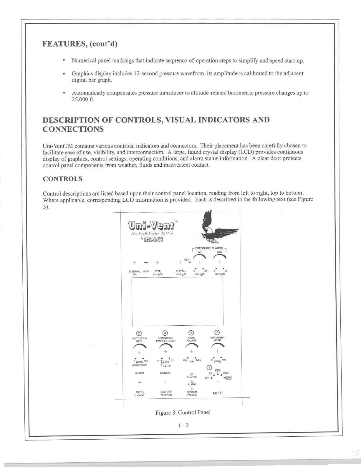
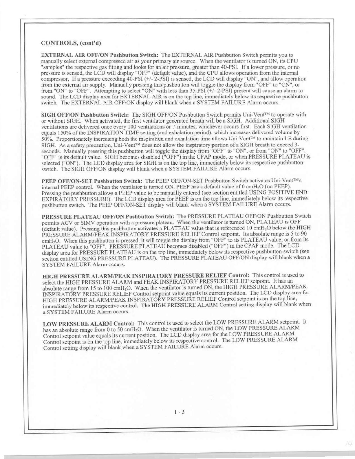
CONTROLS
Control
Where
3).
contains
ease
of
use,
of
graphics,
panel
components
descriptions
applicable,
corresponding
(cont'd)
panel
markings
display
bar
ft.
visibility,
control
are
graph.
compensates
OF
various
settings,
from
listed
includes
CONTROLS,
controls,
and
interconnection. A large,
weather,
based
LCD
that
indicate
12-second
pressure
indicators
operating
fluids
upon
their
information
sequence-of-operation
pressure
transducer
and
conditions,
and
control
waveform,
to
VISUAL
connectors.
liquid
and
alarm
inadvertent
panel
location,
is
provided.
altitude-related
contact.
steps
its
amplitude
barometric
INDICATORS
Their
placement
crystal
display
status
information. A clear
Each
reading
is
from
described
to
simplify
is
calibrated
has
(LCD)
left
in
the
and
pressure
AND
been
carefully
provides
to
right,
following
speed
start-up.
to
the
adjacent
changes
chosen
continuous
door
protects
top
to
text
up
to
to
bottom.
(see
Figure
|
|
|
orana.
|
|
|
VENTILATION
|
pe
|
даун”
Rabat
Vat
Manas
par
ün
=
© © ©
RATE
e
MUTE/
CANCEL
rer
EB
INSPRATION
tive e RATIO
an
m
+ +
TRIGGER
Gk
ο
saa
κά
M
volume
PRESSURE
IM
-+
ON
Mad
=
пом.
YY
а
대
새야
a
one
a
ans
system
FARE
ALARMS
iow
1
CN
ee
ema
|
ножен
a
©
Me
Tome
y
MODE
Figure
3.
Control
1-2
Panel
Page 14
CONTROLS,
EXTERNAL
manually
"samples"
pressure
compressor.
from
from
sound.
switch.
SIGH
or
ventilations
equals
50%.
SIGH.
seconds.
"OFF"
selected
switch.
PEEP
internal
Pressing
EXPIRATORY
pushbutton
select
the
is
sensed,
the
external
"ON"
to
The
The
OFF/ON
without
SIGH.
150%
Proportionately
Asa
safety
Manually
is
its
("ON").
The
OFF/ON-SET
PEEP
the
switch.
(cont'd)
AIR
OFF/ON
external
respective
the
LCD
If a pressure
air
supply.
"OFF".
LCD
EXTERNAL
are
of
default
SIGH
control.
pushbutton
Attempting
display
Pushbutton
When
delivered once
the
INSPIRATION
increasing
precaution,
pressing
value.
The
LCD
OFF/ON
PRESSURE).
The
Pushbutton
compressed
gas
fitting
will
display
exceeding
Manually
area
for
EXTERNAL
AIR
OFF/ON
Switch:
activated,
every
both
Uni-Vent™
this
pushbutton
SIGH
becomes
display
display
Pushbutton
When
the
ventilator
allows a PEEP
The
PEEP
OFF/ON-SET
air
as
and
looks
"OFF"
40-PSI
pressing
to
select
The
the
first
100
TIME
the
area
for
will
Switch:
value
LCD
Switch:
your
"ON"
display
SIGH
ventilator
ventilations
setting
inspiration
does
disabled
SIGH
blank
is
display
The
primary
for
an
air
(default
(+/-
2-PSI)
this
pushbutton
with
AIR
is
will
OFF/ON
(and
not
allow
will
toggle
("OFF")
is
on
when a SYSTEM
The
PEEP
turned
to
be
manually
area
display
EXTERNAL
air
source.
pressure,
value),
is
sensed,
less
than
on
the top
blank
when a SYSTEM
Pushbutton
generated
or
7-minutes,
exhalation
and
exhalation
the
the
display
in
the
top
OFF/ON-SET
ON,
PEEP
entered
for
PEEP
will
blank
AIR
When
greater
and
will
35-PSI
breath
inspiratory
the
line,
has a default
is
when a SYSTEM
than
the
CPU
the
LCD
toggle
(+/-
line,
immediately
Switch
will
whichever
period),
time
allows
portion
from
"OFF"
CPAP
immediately
FAILURE
Pushbutton
(see
section
on
the top
Pushbutton
the
ventilator
40-PSI,
allows
operation
will
display
the
display
2-PSI)
present
below
FAILURE
permits
be a SIGH.
occurs
which
increases
Uni-Vent™
of a SIGH
to
"ON",
mode,
or
when
below
Alarm
occurs.
Switch
value
of 0 cmH,O
entitled
line,
immediately
FAILURE
Switch
permits
is
turned
Ifa
lower
from
"ON",
from
"OFF"
will
its
respective
Alarm
Uni-Vent™
Additional
first.
Each
delivered
to
breath
or
from
PRESSURE
its
respective
activates
USING
Alarm
you
ON,
its
pressure,
the
internal
and allow
to
"ON",
cause
an
occurs.
to
operate
SIGH
SIGH
volume
maintain
to
exceed
"ON"
PLATEAU
pushbutton
Uni-Vent™'s
(no
PEEP).
POSITIVE
below
its
occurs.
to
CPU
or
no
operation
or
alarm
to
pushbutton
with
ventilation
by
I:E
during
3-
to
"OFF".
is
END
respective
PRESSURE
permits
(default
PRESSURE
cmH;0.
PLATEAU
display
section
SYSTEM
HIGH
select
absolute
INSPIRATORY
HIGH
immediately
a
LOW
has
PRESSURE
the
PRESSURE
SYSTEM
PRESSURE
absolute
an
Control
Control
Control
ACV
value).
When
area
entitled
FAILURE
HIGH
range
setpoint
setpoint
setting
PLATEAU
or
SIMV
Pressing
ALARM/PEAK
pushbutton
this
"OFF".
to
value
PRESSURE
for
USING
ALARM/PEAK
PRESSURE
15
from
PRESSURE
ALARM/PEAK
its
below
FAILURE
ALARM
range
value
on
is
display
OFF/ON
operation
pushbutton
this
INSPIRATORY
PRESSURE
PLATEAU
PRESSURE
Alarm
occurs.
ALARM
100
to
RELIEF
respective
Alarm
occurs.
to
O
from
its
equals
line,
top
the
blank
will
Pushbutton
with
a
pressed,
is
PLATEAU).
INSPIRATORY
cmH;0.
INSPIRATORY
control.
Control:
cmH;0.
50
current
immediately
when
pressure
activates
PRESSURE
will
it
PLATEAU
the
on
is
PEAK
and
the
When
Control
The
control
This
When
position.
SYSTEM
a
Switch:
plateau.
PLATEAU
a
toggle
becomes
line,
top
The
INSPIRATORY
ventilator
setpoint
PRESSURE
PRESSURE
HIGH
is
the
The
below
FAILURE
PRESSURE
The
When
the
value
RELIEF
display
the
disabled
immediately
PRESSURE
PRESSURE
turned
is
equals
value
select
to
used
ventilator
LCD
its
is
display
respective
Alarm
ventilator
is
that
Control
"OFF"
from
("
below
PLATEAU
RELIEF
PRESSURE
the
ON,
current
its
RELIEF
ALARM
LOW
the
ON,
turned
for
area
control.
occurs.
PLATEAU
is
turned
referenced
setpoint.
its
to
the
in
")
respective
its
OFF/ON
Control:
RELIEF
HIGH
position.
Control
PRESSURE
LOW
the
LOW
the
LOW
The
setpoint
Control
OFF/ON
ON,
cmH;0
10
absolute
Its
PLATEAU
CPAP
pushbutton
display
This
setpoint.
PRESSURE
The
display
setting
PRESSURE
PRESSURE
PRESSURE
Pushbutton
PLATEAU
below
range
value,
mode.
will
control
It
ALARM/PEAK
display
LCD
the
on
is
will
ALARM
ALARM
is
OFF
the
5
is
from
or
LCD
The
switch
when
blank
used
is
an
has
area
line,
top
blank
setpoint.
ALARM
ALARM
Switch
HIGH
90
to
its
(see
a
to
for
when
It
Page 15
CONTROLS,
VENTILATION
ventilation
breaths
equals
immediately
change
Alarm
INSPIRATION
duration
maximum.
(inspiratory
default
ventilator
Setting
causes
time
RATIO
TIME/I:E
selected.
TIDAL
maximum
of
the
rate for
per
minute
its
current
to
12
occurs,
of
all
Its
time
I:E
ratio
is
turned
INSPIRATION
the
INSPIRATION
and
IE
Control
RATIO
It
will
VOLUME
flow
following
(cont'd)
RATE
position.
above
BPM.
or
the
TIME/I:E
ventilator-delivered
usable
is
of
ratio
are
setpoint
blink
is
equivalent
gas
Control:
ACV
and
SIMV
(BPM).
its
greater
1:2
ON,
Control
When
The
respective
The
VENTILATION
CPAP
mode
RATIO
range
is
than
is
activated
the
INSPIRATION
TIME
TIME
simultaneously
is
on
setting
during
INVERSE
Control:
to
or
gas
combinations:
LCD
limited
expiratory
causes
the
The
approximately
The
VENTILATION
operation.
the
ventilator
display
control.
is
to
bottom
display
During
RATE
selected.
Control:
breaths.
by
the
when
this
the
resulting
be
calculated
displayed
line,
will
I-E
TIDAL
It is
not
is
turned
area
for
VENTILATION
APNEA,
Control
The
INSPIRATION
It
is
adjustable
VENTILATION
time)
are
not
control
TIME/I:E
conditions.
VOLUME
is
I:E
when
in
the
LCD.
immediately
blank
when a SYSTEM
1000mI/sec
External
RATE
operable
ON,
the
the
RATE
setting
in
0.1
RATE
permitted.
tumed
to
its
RATIO
RATIO
Control
Control
to
VENTILATION
The
above
allows
(60
LPM).
Air
(Cylinder)
control
in
CPAP
setting
determines
(RATE = 0).
VENTILATION
RATE
Control
Control
display
TIME/I;E
second
Control
(See
fully
be
calculated. Setting
LCD
its
respective
gas
TIDAL
setting
will
blank
RATIO
increments
setting.
section
counterclockwise
setpoint
display
FAILURE
RATE
to
be
entitled
value
settings
area
control.
delivered
VOLUME
the
Its
range
RATE
Control
setpoint
and
its
LCD
when a SYSTEM
Control
from
0.1
to
Inverse
ALARM
position.
equals
its
the
default
are
changed.
for
INSPIRATION
The
INSPIRATION
Alarm
occurs
over a wide
may
mechanical
is
from 1 to
setpoint
is
on
the
display
FAILURE
sets
the
inspiratory
3.0
seconds
I:E
Ratio's
FUNCTIONS).
When
current
be
I:E
or
CPAP
range.
obtained
position.
RATIO
Inspiration
TIMELE
150
value
bottom
will
the
is
Its
from
line,
A
(1:2)
any
volume
Tidal
VOLUME
initially
LCD
whatever
del"
immediately
SYSTEM
AIR/OXYGEN
oxygen
gas
flow
TIDAL
FAILURE
be
to
or
gas
combinations:
External
calculated
is
Control
displays
corrections
VOLUME.
above
MIXER
delivered.
21
Oxygen
setpoint
"444
are
The
respective
its
Alarm
Control:
has
It
100%
to
to
21
and
displayed
and
equals
value
TIDAL
set"
required,
LCD
control.
occurs
range
a
21%
FIO»
100%
External
External
in
its
VOLUME
then
or
CPAP
The
of
21%
FIO,
21%
FIO;
External
area
The
AIR/OXYGEN
21%
from
from
display
from
Compressed
Internal
Air
Cylinder
External
milliliters
position.
current
the
is
FIO,
FIO,
for
alternately
LCD
TIDAL
for
TIDAL
selected.
air)
(all
from
External
from
Oxygen
External
Air
Air
Compressor
or
Compressor,
Oxygen
When
(ml).
Uni-Vent™'s
first
the
VOLUME
VOLUME
MIXER
100%
to
External
Compressed
Internal
External
and
Oxygen
(Compressor)
ventilator
the
two
or
one
displays
Control
Control
(all
Air
Air
and
"####
Control
setting
allows
oxygen)
(Cylinder)
(Compressor)
Air
Compressor
Air
Internal
or
Internal
is
monitors
CPU
delivered
set"
setpoint
display
air,
may
and
Cylinder
Compressor
Air
Air
Compressor
ON,
turned
and
breaths,
TIDAL
on
is
will
oxygen,
obtained
be
Compressor
or
the
adjusts
while
VOLUME
bottom
the
blank
mixtures
or
from
TIDAL
gas
CPU
the
and
when
the
flow.
makes
"####
line,
a
air
of
following
Its
and
100%
FIO,
from
External
Oxygen
Page 16
CONTROLS,
When
the
Uni-Vent™'s
mode,
FIO,
during
the
AIR/OXYGEN
AIR/OXYGEN
when
an
EXT
ALARM MUTE/CANCEL
Pushbutton
Muting:
period
(see
predetermined
the
pre-existing
When
an
message.
Pressing
will
Ifa
the
described
Canceling:
an
the
apnea.
settings.
the
resume
new
display
Advisory
audible
Cancellation
(cont'd)
ventilator
CPU
monitors
proportions
first
one
or
MIXER
MIXER
AIR
LOW/FAIL,
Switch
can
Depressing
ALARM
mute-period
alarm.
alarm
causing
The
ALARM
ALARM
flashing
alarm
condition
of
that
alarm.
when
the
ALARM
depressed,
When
condition
Alarm
visual
and
FUNCTIONS).
when
of
is
turned
ON,
and
are
based
two
delivered
Control
Control
Pushbutton
either
mute
this
switch
is
condition
LED
alternately
MUTE/CANCEL
the
mute
occurs
The
new
MUTE/CANCEL
the
(see
APNEA
an
alarms
APNEA
the
AIR/
adjusts
on
gas
breaths.
setpoint
setting
display
O,
LOW/FAIL,
an
audible
mutes
the
Alarm
reached
occurs,
period
during
alarm
ALARM
ALARM
and
alarm
OXYGEN
gas
flow
according
flowing
is
flashes,
Pushbutton
the
will
at
Delivered
on
the
bottom
will
or
Switch:
alarm
audible
muting
(audible
the
LCD
at
ends.
mute
period
cause
Pushbutton
MUTE/CANCEL
FUNCTIONS).
controlled
the
Uni-Vent™
allows
MIXER
to
1000ml/sec.
FIO
is
line,
blank
when a SYSTEM
FIO;
Alarm
Depending
signal,
or
component
is
reset
when
alarm
will
resound). A new
ALARM
the
same frequency
Switch
the
causes
of a previous
ALARM
Switch
During
ventilations
to
Control
the
displayed
immediately
occurs.
upon
cancel a particular
of an
MESSAGE
Pushbutton
resume
setpoint value
FIO)
and
The
CPU
alarm
Operating
the
current
as
the
ALARM
alarm,
LED
to
is
pressed.
APNEA
an
that
operation
TIDAL
makes
in
the
LCD.
above
FAILURE
category,
Alarm
alarm
alarm
CENTER
the
accompanying
the
alternately
Switch
automatically
are
VOLUME
any
its
respective
the
alarm
condition
condition
will
LED
to
new
alarm
flash
cancels
alarm
the
at
equals
its
setpoints.
necessary
The
LCD
control.
Alarm
occurs.
ALARM
function.
condition
no
overrides a "muted"
display
audible
stay
on
continuously.
will
and
respond
audible
the
condition,
invoked
ACV,
preset
current
have
position.
In
CPAP
flow
corrections
display
for a predetermined
longer
the
area
The
It
will
MUTE/CANCEL
applies
pertinent
alarm.
no
effect
as
previously
component
cancel
will
it
onset
the
at
or
SIMV
for
blink
or
alarm
It
upon
of
both
of
CPAP
MANUAL
operable
Pressing
is
settings
inspiratory
until
audible
This
MANUAL
this
(LPM).
exceeding
MODE
power
a
operation
transducer
two
this
one
to
equal
and
airway
beep
control
pushbutton
A
40
MANUAL
The
Selector
the
in
Turning
"SELE-CHECK"
the
will
BREATH/TRIGGER
ways.
control
expiratory
time
pressure
is
functions
TRIGGER
pressure
cmHz0.
ACV,
MODE
permitted
is
during
complete
of
heard.
is
not
ventilatory
period.
1.67-seconds,
has
as
contains
depressed,
relieving
BREATH/TRIGGER
Switch
SIMV,
SELECTOR
section
(see
until
begin
in
Pushbutton
normal
reached
MANUAL
a
the
(OFF-A/C-SIMV-CPAP-CAL):
CPAP,
the
CPU
cycle
CPAP
the
In
pressure
and
baseline
TRIGGER
dedicated
MANUAL
mechanism,
Pushbutton
CAL
and
Switch
entitled
"SELF-CHECK"
CAL
SELF-CHECK)
position
Switch:
operation,
consisting
(zero
circuitry
contained
positions.
from
a
mode,
limited
PEEP).
or
backup,
capable
TRIGGER
OFF
successfully
is
(see
only
The
delivers
current
the
of
manual
cmH,0.
40
at
Each
if
of
delivers
this
within
protected
is
AIC,
to
before
section
MANUAL
MANUAL
one
INSPIRATORY
is
breath
time
CPU
a
providing
continuous
a
circuit,
against
MODE
The
SIMV,
initiating
completed.
entitled
BREATH/TRIGGER
BREATH.
delivered
MANUAL
A
MANUAL
a
occurs
failure
manually
gas
peak
limits
accidental
SELECTOR
causes
CPAP
or
operating
Calibration
TRANSDUCER
TIME/TIDAL
flow
a
at
BREATH
BREATH
the
in
triggered
at
flow
inspiratory
contact
Switch
the
the
in
of
CALIBRATION).
Pushbutton
MANUAL
Each
VOLUME
LPM,
30
of
rate
primary
breaths.
liters
30
a
by
microprocessor
selected
the
be
cannot
triggered,
is
system.
For
per
pressure
circular
provides
mode.
pressure
airway
minute
is
BREATH
an
delivered
an
The
long
as
from
guard.
operating
perform
to
Ventilator
as
Page 17
VISUAL
When
within
control
illuminates
MODE
SIMV,
Vmin
when
INSPIRATION/EXHALATION
phase
INSPIRATION/EXPIRATION
POWER
the
LCD's
and
the
the
power
will
INDICATORS
activated,
the
LCD
panel.
When
green.
STATUS
Indicator:
CPAP,
or
Indicator:
a
PLATEAU
of
mechanical
INFORMATION
lower
CPU
validates
check
blank
when
The
POWER
STATUS,
except
activated,
Based
CAL.
Displays
VOLUME
and/or
left
section.
a
portion
a
SYSTEM
INFORMATION
1:
Line
and
for
the
ALARM,
upon
The
MODE
Minute
or
spontaneous
CENTER:
It
usable
of
SELF-CHECK
FAILURE
"EXT
ALARM
the
the
SYSTEM
Indicator
illuminates
source
PWR
INDICATORS
SYSTEM
ALARM
MODE
Indicator
Volume
Indicator:
breaths
display
The
of
power
Alarm
CENTER
ON"
and
SYSTEM
Selector
display
(in
liters)
FAILURE
Alternately
in
will
POWER
when
the
(see
(see
SELF-CHECK).
occurs.
or,
are
FAILURE,
Switch
will
in
the
Alarm
each
operating
blank
INFORMATION
MODE
OPERATING
can
display
continuously
and
FAILURE
blank
ACV
displays
when
CHARGE
setting,
this
when
mode,
occurs.
the
mode,
a
SYSTEM
SELECTOR
POWER
The
the
following
displayed.
LED's
LED's
illuminate
indicator
a
SYSTEM
blanks during
"INSPIRATION"
blanks
during
FAILURE
CENTER
SWITCH
SELECTION
POWER
INFORMATION
messages:
All
indicators
which
red,
displays,
FAILURE
SIMV,
or
CAL.
Alarm
(PIC)
occupies
is
in
any
&
are
appear
the
respectively,
Alarm
CPAP
"EXHALATION"
The
position
STOPPING)
displayed
elsewhere
CHARGE
occurs.
and
occurs,
a
2-line
except
CENTER
ASSIST,
CAL
on
the
LED
or
area
in
OFF
during
display
Line
Line
Line
Line
"EXT
PWR
denotes
POWER
external
Battery
30-minutes
internal
denotes
charge
operation,
a
low
LOW/FAIL
power
Line
Line
Line
Line
Line
icon
batteries
(1)
(see
"EXTPWR
1:
"EXT
1:
1:
"EXT
Blank
1:
ON"
denotes
external
is
connected.
Battery
2:
Battery
2:
2:
Battery
Battery
2:
Blank
2:
denotes
"OK"
remaining
of
can
operation
section
internal
batteries
PWR
CHK
operation
power
Alarm
icon
icon
icon
icon
(1)
charge
provide
internal
from
entitled
ALARMS)
are
LOW"
FAIL"
FUSE"
from
source
(see
section
or,
"OK
"LOW"
CHG"
"ON
"CHK
operation
or,
(2)
at
least
batteries
being
or,
or,
(flashing,
an
voltage
external
and
entitled
or,
or,
FUSE"
30-minutes
(flashing,
from
in
conjunction
having
or,
(2)
charged
internal
in
and
see
description
power
works
in
ALARMS).
see
batteries
with
operation.
of
less
than
conjunction
currently
below)
source.
conjunction
description
external
have
"EXT
This
line
that
have
power
Battery
30-minutes
with
external
less
or,
PWR
with
is
blank
below)
more
operation,
icon
of
power
than
30-minutes
LOW"
the
EXTERNAL
when
or,
than
"LOW"
remaining
no
Page 18
VISUAL
INDICATORS,
of
operating
LED
illuminates,
blank
if
no
OPEN
or
or
MISSING
missing
1.
2.
3.
(cont'd)
time
capability.
when
battery
fuses
is
sensed.
FUSES:
under
the
During normal
&
Charge
Prior
&
Charge
During
Charge
Fuse
a.
EXT
continues
PIC
b.
c.
When
EXT
PIC
d.
to
beginning
Fuse
a.
Operation
b.
PIC
normal
Fuse
a.
Operation
b.
PIC
Battery
charging
Line
Line
Line 1 flashes
opens
Line 2 flashes
current
The
following
PWR
Alarm
PWR
operation
POWER
operation
opens
(or
FAIL/DISCONNECT
from
displays
1
Mute/Cancel
FAIL/DISCONNECT
flashes
1
operation
opens
(or
begins
(or
is
continues
icon
"ON
CHG"
is
flowing
INFORMATION
circumstances:
from
external
is
removed):
"EXT
"EXT
from
is
removed):
from
internal
"CHK
from
external
from
battery
battery.
PWR
pushbutton
CHK
external
EXT
external
icon
internal
removed):
is
displayed
into
the
power,
Alarm
FAIL".
Alarm
FUSE".
power,
battery.
FUSE".
power,
the
power.
"CHK
battery
CENTER
the
External
activates,
is
pressed,
reset,
is
the
External
Battery
FUSE".
,
and
the
pack.
is
Power
operation
the
Operation
CHARGE
This
line
able
Operation
Power
will
to
identify
Operation
&
open
PEAK
AIRWAY
PEAK
AIRWAY
MEAN
MEAN
DIGITAL
pressure.
markers
Indicator
HIGH
PRESSURE
GRAPH.
The
AIRWAY
AIRWAY
MEAN
appear
and
AIRWAY
BAR
Its
absolute
at 0,
display
LOW
ALARM
Setpoint
4.
Prior
connected),
PRESSURE
PRESSURE
PRESSURE
PRESSURE
PRESSURE
GRAPH
range
50
and
will
blank
AIRWAY
Setpoint
indicators
to
beginning
a.
The
b.
The
tone
Indicator
to
(PIP-PEEP) X —
Indicator:
is
from
100
when a SYSTEM
PRESSURE
Indicators
are
operation
and
the
Battery
ventilator
SYSTEM
sounds
(non-mutable).
Indicator:
display
Indicator:
following
the
Indicator
The
-10
to
cmH,O.
positioned
Vertical
from
Operation
will
not
operate,
FAILURE
Displays
Displays
TOTAL CYCLE
DIGITAL BAR
+100
ALARM
appear
according
the
will
blank
algorithm:
display
cmH,O.
resolution
FAILURE
Setpoint
as
small
internal
&
Charge
its
LED
illuminates
PEAK
when
the
MEAN
I
TIME
will
blank
GRAPH
Increment
is 2 cmH
Alarm
horizontal
to
their
respective
battery
(external
Fuse
LCD
will
not
and a continuous
AIRWAY
a
SYSTEM
AIRWAY
-
when a SYSTEM
occurs,
Indicators:
+
indicator
markings
O/bar.
lines
to
alarm
power
opens
(or
illuminate.
PRESSURE
FAILURE
PRESSURE.
PEEP
FAILURE
provides
appear
The
DIGITAL
The
HIGH
the
right
control
is
not
is
removed):
of
the
Alarm
Uni-Vent™
continuous
every
10
and
LOW
of
the
DIGITAL
settings
previous
occurs.
Alarm
display
emH3O,
BAR
GRAPH
AIRWAY
and
reposition
breath.
calculates
occurs.
of
airway
numerical
BAR
The
Page 19

VISUAL
whenever
LOW
Alarm
Pay
most
adjacent
display
CHARGE
current
Control
and
The
called
Indicator
OFF,
each
information
OPERATING
period.
an
AIRWAY
is
triggered
Indicator: The
recent
digital
will
is
flowing.
Setting
lower
lines.
ALARM
LCD
display
the
ALARM
and
whenever
alarm.
During
INDICATORS,
alarm
control
PRESSURE
and
Pay
12-second
bar
graph.
blank
when a SYSTEM
Indicator: The
Indicators:
INDICATORS
allocates
MESSAGE
SYSTEM
an
alarm
Alarms
on
are
alarms,
ALARM,
an
ADVISORY
OPERATING
(cont'd)
is
adjusted.
ALARM
blanks
when a SYSTEM
indicator
period.
see
Airway
Markings
green
All
up
to
FAILURE
causing
categorized
section
the
ALARM
Setpoint
Setpoint
represents a continuous
pressure
along
FAILURE
CHARGE
control
4-lines
of
CENTER
LED's.
condition
as
OPERATING,
entitled
Indicator
ALARM
ALARMS
indicator
Indicator
FAILURE
amplitude
the
horizontal
Alarm
Indicator
settings,
alarm
(AMC).
pressing
The
other
ALARM
except
message
ALARM
than
LED
Each
FUNCTIONS).
MUTE/CANCEL
vertical
blinks
and
along
axis
occurs.
LED
MODE
information
alarm
Indicator
SYSTEM
NON-OPERATING,
remains
resolution
when a HIGH
Alarm
occurs.
updating
the
represent
illuminates
SELECTOR
is
displayed
FAILURE
illuminated,
is 2 cmH,O.
display
vertical
LED
axis
1-second
whenever
in a dedicated
in
illuminates,
occurs.
or
When
the
but
tums
the
PRESSURE
of
airway
is
calibrated
intervals.
sufficient
Switch,
the
ADVISORY
stops
ALARM
appear
area.
LCD
and alternately
An
audible
flashing,
The
respective
or
LOW
pressure.
to
coincide
The
P,y
battery
on
This
dedicated
except
for
audible
signal
Indicator
signal
(for
detailed
is
muted
during
PRESSURE
It
display's
Indicator
recharging
the
LCD's
the
ALARM
flashes
accompanies
during
the
mute
LED
OFF.
HIGH
with
upper
area
ON
or
the
the
is
and
an
BATTERY
displays:
BATTERY.
EXTERNAL
than
SOURCE/CONNECTIONS
LOW
consecutive
PRESSURE
non-operating
setpoint
DISCONNECT
displays:
operating
HIGH
breaths,
displays:
will
Alarm
APNEA
deflections
SPONTANEOUS
seconds
RATE
BATTERY
VDC.
10.9
PRESSURE
indicator,
DISCONNECT
alarm
PRESSURE
2-seconds
or
HIGH
if
blank
LCD
Alarm:
(based
LESS
LOW/FAIL
AMC
The
POWER
When
Alarm:
breaths
have
and
PEAK
-
occurs.
alarm
during
Alarm:
occurs.
PRESSURE
non-operating
a
setpoint
ACV
been
BREATHING
a
on
THAN
Alarm:
LOW/FAIL
will
LOW
activated
causes
INSPIRATORY
a
Initiates
-
Alarm:
continuously,
indicator,
and
sensed.
30-second
6-BPM
-
if
blank
Alarm:
the
EXT
or
Initiates
LCD
its
setpoint
The
PRESSURE
CHECK
Initiates
PEAK
-
alarm
during
SIMV:
When
or
moving
APNEA.
or
a
Initiates
when
when
RECHARGE/REPLACE
non-operating
a
Initiates
AMC
PWR.
when
setpoint
PRESSURE
ALARM
a
CIRCUIT
when
causes
and
INSPIRATORY
occurs.
PRESSURE
a
initiates
activated
APNEA.
average).
when
displays:
AMC
The
fails
PIP
indicator
indicator
SETTINGS
disconnect
CONNECTIONS
exceeds
PIP
LCD
its
setpoint
The
when
the
CPAP:
AMC
The
low
alarm
EXTERNAL
to
TOO
will
ALARM
approximately
AMC
When
will
BATTERY
occurs.
external
will
is
power
blank
the
exceed
blink.
to
or
LOW
alternately
Alarm.
in
sensed
HIGH
the
setpoint
PRESSURE
indicator
SETTINGS
displays:
initiates
‘when
activated
blank
condition
battery
is
PACK,
sensed
(as
POWER
non-operating
a
if
PRESSURE
LOW
LOW
the
or
indicator
will
19-seconds
a
if
activated
When
PRESSURE.
with
blink,
patient
DISCONNECT.
PRESSURE
to
TOO
alternately
APNEA
spontaneous
no
AMC
the
non-operating
sensed.
at
LOW
the
circuit.
Alarm
blink.
or
HIGH
Alarm.
have
CHECK
-
displays:
When
BATTERY
External
the
CHECK
-
alarm
ALARM
AMC
the
The
HIGH
When
The
setpoint
When
HIGH
blink,
elapsed
PATIENT
breathing
APNEA
alarm
activated
LOW/FAIL
Power
POWER
occurs.
setpoint
displays:
AMC
PRESSURE
activated
will
AMC
for
activated
PRESSURE.
the
with
no
and
is
CPAP
-
occurs.
AMC
the
Jack),
for
LOW
blank
will
Alarm
the
blank
consecutive
four
AMC
the
PRESSURE
LOW
pressure
FOR
detected
AVERAGE
or
two
ifa
AMC
if
The
for
less
is
LCD
non-
a
AMC
10-
Page 20
VISUAL
HIGH
activated
HIGH
O,
AMC
will
EXT
When
LOW/FAIL
FIO,
to
meet
SOURCE/SETTINGS/CONNECTIONS
PRESSURE
ALARM
indicators,
ALARM
SETTINGS
occurs.
V;
displays:
will
INDICATORS,
PEEP
Alarm:
the
AMC
PEEP.
LOW/FAIL
displays:
blank
AIR
activated
Alarm:
Alarm:
blank
The
if a non-operating
LOW/FAIL
or
EXT
Initiates
its
proportion
ALARM
setpoints
and
both
SETTINGS
REVERSED
Initiates
DELIVERED
-
Vr
in
the
Initiates
displays:
AMC
will
Alarm:
O,
the
CPAP
Initiates
LOW/FAIL - CHECK
Alarm:
AMC
displays:
AIR.
The
when
of
the
SETTINGS
are
reversed
indicators
Alarm.
or
when
mode,
(cont'd)
when
the
HIGH
PEEP - INSPIRATION
blank
if a non-operating
when
alarm
occurs,
Initiates
EXT
AMC
will
the
oxygen
gas
mixture.
Alarm:
(i.e.:
low
adjacent
When
activated
PRESSURE
delivered
tidal
TIDAL
VOLUME
or
if a non-operating
inspiratory
low
pressure
OXYGEN
when
low
AIR
LOW/FAIL - CHECK
blank
if a non-operating
component
When
activated
or
FIO,.
The
Initiates
setpoint
to
the
ALARM
volume
is
DIGITAL
the
AMC
SETTINGS.
does
DOES
cycle
begins
before
BEGAN
alarm
occurs.
is
sensed
SOURCE/CONNECTIONS,
pressure
or
set
alarm
is
the
air
the
AMC
will
when
the
higher
BAR
displays:
not
equal
NOT
occurs.
AMC
EQUAL
BEFORE
from
an
sensed
AIR
alarm
component
displays:
blank
HIGH
than
the
GRAPH,
PRESSURE
The
AMC
set
tidal
end
expiratory
END
PRESSURE
external
from
if a non-operating
PRESSURE
high
alternately
SET
oxygen
O,
LOW/FAIL
an
external
SOURCE/CONNECTIONS,
occurs.
of
the
AIR/OXYGEN
FIO) - GAS
ALARM
setpoint).
blink
ALARM
will
blank
if a non-operating
volume.
TIDAL
When
VOLUME
pressure
supply.
source
Both
during a PRESSURE
SETTINGS - ALARM
plateaus.
PLATEAU
When
or
of
compressed
MIXER
MIX
ERROR.
alarm
occurs.
and
LOW
Control
activated
or
Vr.
activated
0).
EXT
PRESSURE
setpoint
the
AMC
The
When
The
AIR
is
unable
CHECK
alarm
AMC
or
the
AMC
air.
COMP
volume.
AMC
INVERSE
AMC
The
TRANSDUCER
is
RECALIBRATE
MEMORY
Alarm:
When
will
blank
L:E
displays:
will
AMC
stopped
SYSTEM
occurred.
VENTILATOR
conditions
will
will
an
INSPIRATION
time
TIME
SIGH
prematurely.
CHECK
FAILURE
This
will
the
cause
display:
abbreviated
exceed
to
TRUNCATED
breath
Initiates
activated
if
NON-OPERATING
Alarm:
INVERSE
blank
CALIBRATION
TRANSDUCER
alarm
FAIL
not
ALARM
VENTILATOR
description
TIME
3-seconds.
that
when
the
a
non-operating
Initiates
the
in
When
SYSTEM
or
Alarm:
usually
is
Alarm:
cause
LED
ADVISORY
TRUNCATED
TO
exceed
would
AMC
I:E
CPAP
LCD
the
to
the
of
is
It
3-SEC
the
-
activated
FAILURE
internal
displays:
alarm
when
INSPIRATORY
mode,
or
FAILURE
LED,
related
Initiates
to
illuminate.
failure.
ALARMS
disabled
NOTE
-
3.0-seconds
compressor
occurs.
ALARMS
inspiratory
if
or
ABORT
the
TRANSDUCER
illuminates
hardware
a
to
when
blank,
DETECTED
TO
the
in
L-TIME
COMP
time
TIME
SYSTEM
a
Alarm:
displays:
AMC
Alarm
when
any
some
and
not
will
It
3-SEC
CPAP
&
truncated
is
output
COMPRESSOR
-
becomes
LONGER
FAILURE
Initiates
TRANSDUCER
CALIBRATION
occurs.
is
CPU
problem
seven
of
one
be
may
the
cause
followed
Alarm:
mode.
The
LE.
but
When
will
does
when
forced
and
operator
Initiates
AMC
OUTPUT
longer
THAN
Alarm
the
to
cause
will
ventilator
correctable.
SYSTEM
FAILURE
by
when
activated
will
activate
not
produce
not
its
expiratory
than
EXHALATION
occurs.
TRANSDUCER
CALIBRATION
ABORT.
shutdown
the
failure
FAILURE
CODE
control
the
if
blank
this
intended
LOW/FAIL
The
operation
LCD
causing
A
AMC
non-operating
a
alarm.
contribution
time.
TIME
CALIBRATION
will
AMC
or
blank.
to
conditions
VENTILATOR
to
LED
number
(a
#
settings
would
displays:
to
COMP.
or
activated
When
INVERSE
or
ABORT
a
illuminate.
-
if
blank
failure
CPU
occur.
FAIL
1
from
cause
INSPIRATION
occurs.
alarm
tidal
The
the
I:E.
process
a
has
These
Alarm
LCD
The
and
7),
to
inspiration
A
Page 21
VISUAL
PLATEAU
volume
LESS
Vr
SETTINGS
liters
60
DELIVER
PREVENTATIVE
whichever
CONTACT
EXTENDED
has
PATIENT
EXTERNAL
external
SOURCE/CONNECTIONS
occurs.
TOTAL
and
of
at
displays:
operating
INDICATORS,
VOLUME
by
more
THAN
per
minute
SET
occurs
CUSTOMER
occurred.
USE.
power
FLOW
internal
least
TOTAL
alarm
compressor)
10
than
SET
VOLUME.
Alarm:
VOLUME
first.
NON-USE/STORAGE
When
The
POWER
operation.
BACKUP
LPM
FLOW
occurs.
(cont'd)
Alarm:
5%,
When
Initiates
(LPM).
MAINTENANCE
activated
and a total
When
or
V;
When
activated
SERVICE.
the
AMC
will
FAILURE
When
or
Alarm:
exceeding
tidal
BACKUP - CONTACT
Initiates
activated
The
whenever
SETTINGS.
AMC
blank
activated
EXT
when
the
AMC
will
activated,
Alarm:
the
AMC
The
AMC
Alarm:
displays:
if a non-operating
Alarm:
the
PWR
FAIL/DISCONNECT.
Initiates
set
flows
volume
of
delivered
AMC
displays:
blank
in
the
sum
of
the
AMC
The
AMC
Initiates
displays:
will
blank
Initiates
EXTENDED
Initiates
when
by
at
AMC
+/-
least
whenever
displays:
the
50%
200ml
CUSTOMER
PRESSURE
PLATEAU
the
CPAP
mode,
the
flows
of
the
displays:
will
after
at
alarm
backup
for
V;
SETTINGS - I-TIME X FLOW
blank
in
2000-hours
PREVENTATIVE
if a non-operating
power-up
5-consecutive
for
after
NON-USE/STORAGE
occurs.
external
EXT
PWR
The
flow
sensor
this
alarm
SERVICE.
PLATEAU
VOLUME - DELIVERED
or
if a non-operating
selected
the
CPAP
of
6-months
power
FAIL/DISCONNECT - CHECK
AMC
to
tidal
gases
mode.
cumulative
MAINTENANCE
alarm
fails,
will
blank
detects
breaths.
the
operate.
The
AMC
volume
would
occurs.
of
continuous
-
or
is
if a non-operating
sum
There must
When
will
is
alarm
exceed a flow
use,
or
TEST
disconnected
of
the
activated
blank
less
than
set
tidal
VOLUME
occurs.
rate
UNABLE
12-months,
DUE
-
non-use/storage
BEFORE
during
POWER
alarm
flows
(Oz,
Air,
be a total
flow
the
AMC
if a non-
rate
of
TO.
CONNECTIONS
OXYGEN
pressure
D.LS.S.
AIR
(medical-grade
D.LS.S.
Filter/Moisture
GAS
LD.
TRANSDUCER:
ventilator
EXHALATION
disposable
EXTERNAL
Supply
INLET:
reducer
Oxygen X D.LS.S.
INLET:
6'
Air,
OUTLET:
corrugated
circuit
ventilator
external
or
[CAUTION
[
DO
The
connect
NOT
EXTERNAL
Nominal
(medical-grade
Nominal
only),
Long,
Trap
hose
POWER
50
electric
or
interconnection.
for
whenever
pressure,
Low
(see
Figure
pressure,
Low
transducer
VALVE:
circuit
JACK:
volt
11-15
external
POWER
50
PSI
only),
Oxygen,
input,
PSI
compressor
external
22mm
4).
fits
(see
hose
pressure,
Low
exhalation
External
power
sources
power
JACK
input,
D.I.S.S.
PTLOX;
6'
Long,
D.I.S.S.
(oil-less
Note:
air
is
provided
tapered
male
I.D.
3/16"
4).
Figure
fits
valve
power
via
source
rated
includes
pins
oxygen,
or
on-board
for
interconnection.
male-thread.
air,
To
tubing.
This
1/4"
Figure
(see
source
12
higher
containing
filtered).
and
protect
by
an
connection.
Connects
connector
tubing.
LD.
4).
connection.
Power
VDC
than
male-thread.
aircraft
the
15
generated
Connects
Use
ventilator
electric
Connects
ventilator
colored
is
Connects
connector
This
Cable
or
volts
signals
for
air
Connects
(provided).
lower
Connects
source.
of
output
to
pressure
high
the
and
dirt
from
compressor.
disposable
to
pressure
green.
ventilator
is
COMMUNICATIONS
the
exhalation
colored
ventilator
11
than
to
output
of
Use
the
cylinder
air
hose,
condensate,
ventilator
transducer
aluminum.
clear
Universal
to
(see
volts
oxygen
high
D.L.S.S.
to
valve
SPECIFICATIONS).
cylinder
pressure
Air
an
use
circuit
control
Power
AC
reducer
Air
22mm
pressure
disposable
PORT
hose,
X
Inlet
port
to
]
|
1-10
Page 22
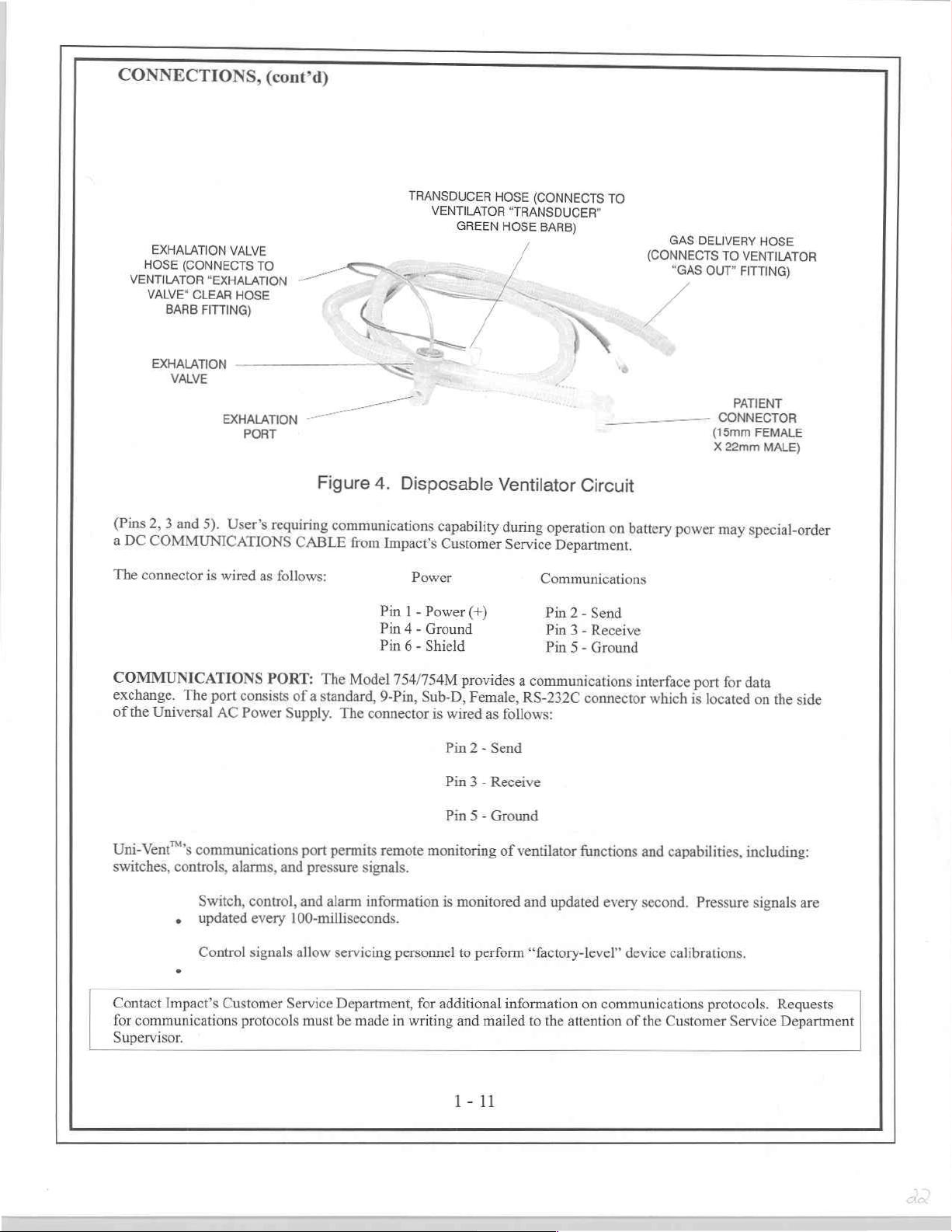
CONNECTIONS,
(cont'd)
EXHALATION
HOSE
VENTILATOR
(Pins
a
DC
The
(CONNECTS
VALVE"
EXHALATION 一 一
2,
COMMUNICATIONS
connector
"EXHALATION
CLEAR
BARB
FITTING)
VALVE
3
and
5).
is
VALVE
TO
HOSE
АГАТ
mi
User’s
wired
jon
requiring
CABLE
as
follows:
~
一
一 一 -
sil
Figure
4.
communications
from
Pin
Pin
Pin
TRANSDUCER
VENTILATOR
GREEN
>
3
Disposable
capability
Impact’s
Power
Power
-
1
Ground
-
4
Shield
-
6
Customer
HOSE
“TRANSDUCER”
HOSE
y
/
/
<
Ventilator
during
Service
(+)
(CONNECTS
BARB)
=
N
operation
Department.
Communications
Pin
Pin
Pin
TO
—
Circuit
on
Send
-
2
Receive
-
3
Ground
-
5
battery
GAS
“GAS
———
power
DELIVERY
TO
OUT”
CONNECTOR
(15mm
X
22mm
may
(CONNECTS
J
HOSE
VENTILATOR
FITTING)
PATIENT
FEMALE
MALE)
special-order
COMMUNICATIONS
exchange.
of
the
Uni-Vent™’s
switches,
Contact
for
communications
Supervisor.
The
port
Universal
Impact’s
AC
communications
controls,
Switch,
+
updated
Control
Customer
PORT:
consists
Power
alarms,
and
control,
every
signals
protocols
of
a
standard,
Supply.
port
pressure
and
100-milliseconds.
allow servicing
Service
must
The
Model
The
connector
permits
signals.
alarm
information
Department,
be
made
754/754M
9-Pin,
Sub-D,
remote
personnel
for
in
writing
provides
Female,
is
wired
as
Pin
2
-
Send
Pin
3
-
Receive
Pin 5 -
Ground
monitoring
is
monitored
to
perform
additional
and
mailed
1-11
a
communications
RS-232C
follows:
of
ventilator
and
updated
“factory-level”
information
to
the
attention
interface
connector
functions
on
communications
every
device
of
which
and
second.
the
port
for
data
is
located
capabilities,
Pressure
calibrations.
protocols.
Customer
on
including:
signals
Service
the
side
are
Requests
Department
Page 23
OPERATING
Uni-Vent™
AC
Power
DC
EXTERNAL POWER
12-volt
An
VAC,
ranging
The
The
Uni-Vent™
When a live
external
and
activates
from
Two
2AG,
fuse
battery
CONTROLS,
additional
is
Supply
operating
battery.
optional
black
MODE
internal
external
effects
Universal
50
to
400
from
input
is
external
power
the
10A
fuse.
battery
icon
"ON
information.
designed
automatically
voltages,
Hz
16
to
lead
Selector
designed
failure
EXTERNAL POWER
power
fuseholders
The
CHG"
VISUAL
POWER
to
operate
within
JACK. A 12
AC
Power
(voltage
30
volts.
is
positive,
Switch
to
give
power
source
occurs,
to
the
external
are
fuse
closest
operation
will
INDICATORS
SELECTION
from
accepts
the
range
VDC
Supply
and
line
The
input
white
acts
as a master
operating
is
Uni-Vent™
source.
located
to
the
and
charging.
not
display
various
input
voltages
of
11 to
Power
(standard
frequency
leads
provided
is
negative.
power
power
applied,
adjacent
internal
automatically
FAILURE
to
top
cover
POWER
if
their
AND
CONNECTIONS
&
voltages
sensing
the
respective
and
from
15
volts
Cable
is
with
is
require a mating
Do
not
switch.
priority
batteries
switches
Alarm.
battery
effects
external
INFORMATION
STOPPING
frequencies
90
to
265
(negative
provided
the
automatic),
attach
to
When
compartment
fuse(s)
for
Model
the
Use
this
external
are
automatically
to
external
power
is/are
-
POWER
(see
volts
AC,
ground),
operation
754M),
and
permits
connector
braided
switch
power
rather
its
internal
power
door.
operation
CENTER
blown
INFORMATION
SPECIFICATIONS).
47
to
440
Hz.
may
be
connected
from a vehicular
is
operable
shield.
to
initiate
battery
Each
or
from
use
from
and
polarity
or
cease
than
its
internal
placed
on
pack
reappears,
fuseholder
and
battery
messages
missing.
nominal
external
must
charge.
for
operation
charging.
for
See
CENTER,
Its
Universal
directly
operation.
operating
"EXT
DESCRIPTION
to
the
source
or
115/230
DC
voltages,
be
observed.
battery
pack.
When
an
power
will
switch
contains a type
The
PWR"
for
external
other
and
OF
Page 24
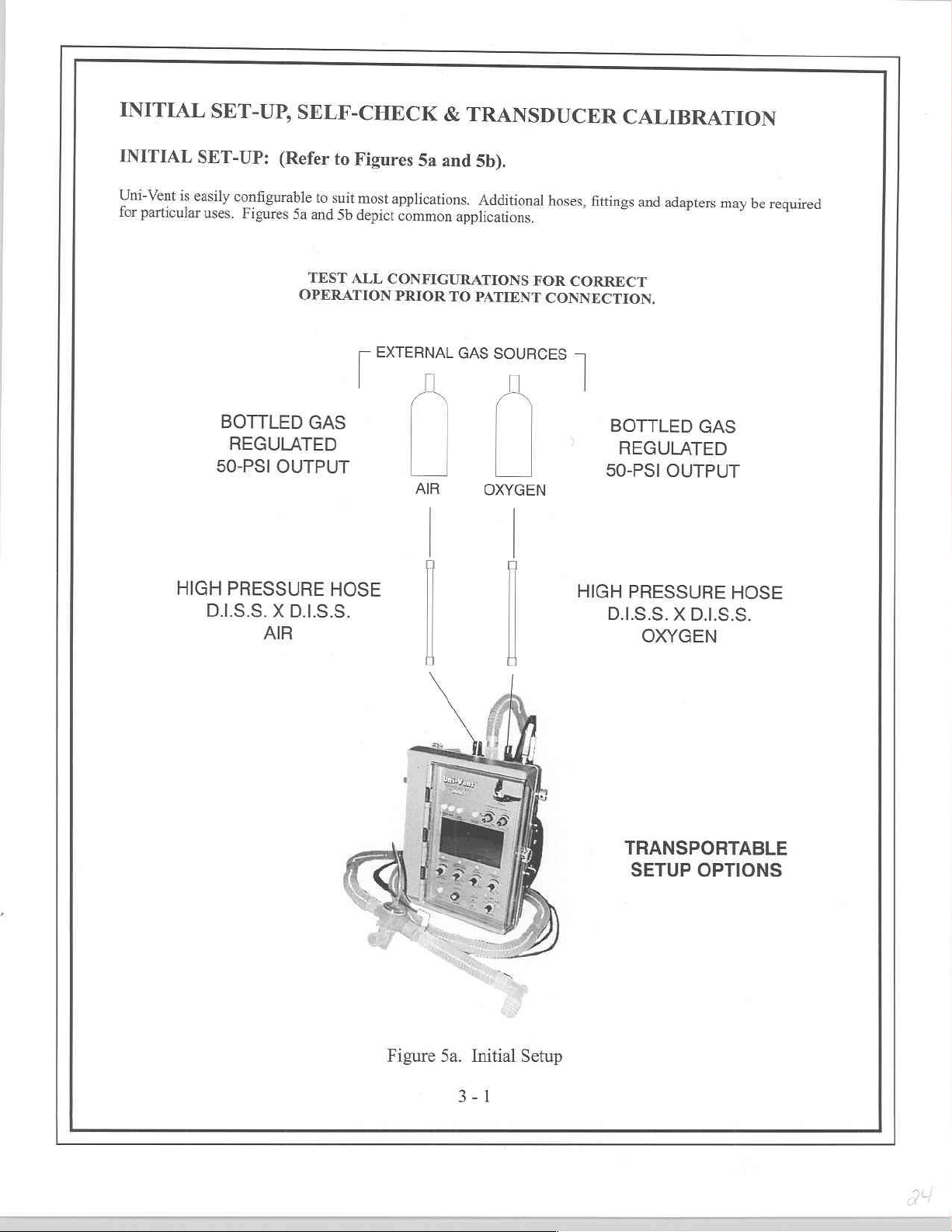
INITIAL
INITIAL
Uni-Vent
for
is
particular
SET-UP,
SET-UP:
easily
configurable
uses.
Figures
BOTTLED
REGULATED
50-PSI
SELF-CHECK
(Refer
OUTPUT
to
to
suit
5a
and
Sb
TEST
OPERATION
GAS
Figures
ALL
5a
most
applications.
depict
common
CONFIGURATIONS
PRIOR
Г
EXTERNAL
AL
{
AIR
&
TRANSDUCER
and
5b).
Additional
applications.
TO
PATIENT
GAS
SOURCES
IL
(
|
| |
OXYGEN
hoses,
fittings
FOR
CORRECT
CONNECTION.
|
CALIBRATION
and
adapters
BOTTLED
REGULATED
50-PSI
OUTPUT
may
GAS
be
required
HIGH
D.1.S.S.
PRESSURE
X
D.1.S.S.
AIR
HOSE
HIGH
PRESSURE
D.1.S.S.
OXYGEN
TRANSPORTABLE
SETUP
X
D.1.S.S.
OPTIONS
HOSE
Figure
5a.
3-1
Initial
Setup
Page 25
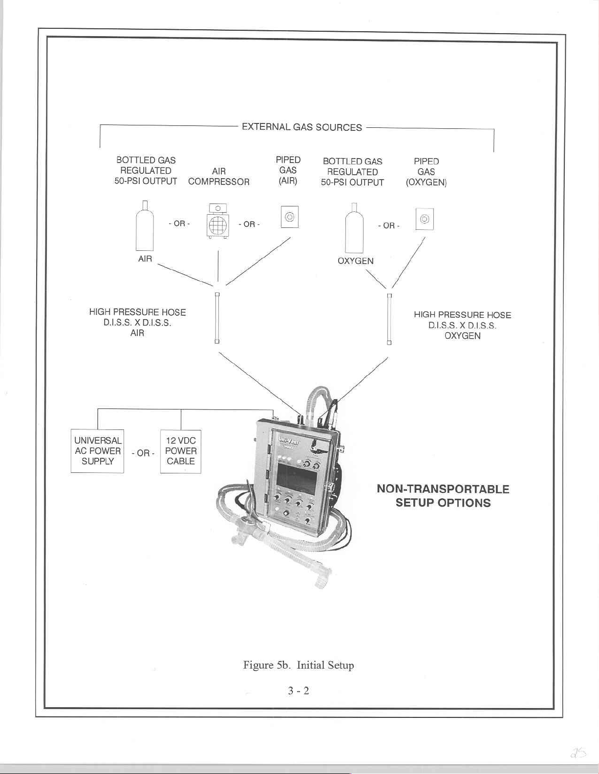
Do
BOTTLED
REGULATED
50-PSI
HIGH
PRESSURE
0.1.5.5.
OUTPUT
[
a
n
Х
0..5.5.
AIR
GAS
-OR
HOSE
AIR
COMPRESSOR
|
|
ロ
EXTERNAL
-OR-
^
GAS
PIPED
GAS
(AIR)
©
SOURCES
BOTTLED
REGULATED
OUTPUT
50-PSI
5
OXYGEN
]
GAS
-OR-
n
PIPED
GAS
(OXYGEN)
HIGH
PRESSURE
DISS.XDIS.S.
OXYGEN
|
HOSE
L
p
AC
POWER | -OR- | POWER
SUPPLY
12
VDC
Figure
5b. Initial
3-2
Setup
NON-TRANSPORTABLE
SETUP
OPTIONS
Page 26
SELF-CHECK
Uni-Vent™
SIMV,
or
checking
The
SELF-CHECK
verify
external
settings.
NOTE
If
external
PSI)
at
the
WARNING
SELF-CHECK
that
the
TRANSDUCER
SELF-
CHECK
information
SELF-CHECK
Operation
Tf
Uni-Vent™
to
its
OFF
-
DO
NOT
SELF-CHECK
exceeds
CHECK
undergoes a self-checking
CPAP;
is
+/- 1 cmH,
will
or
from
not
repeated
process
power/internal
oxygen
time
position
SELF-CHECK
must
process
stored
failure.
begins
fails
ATTEMPT
will
cause
and/or
be
in
immediately
SELF-CHECK, a VENTILATOR
and
automatically
an
CAL
to
if
the
operator
consists
battery
external
is
performed
connection
to
sense a residual
memory.
then
PATIENT
from
audible
Accordingly,
following
repeat
its
last
tone
process
ACV,
SIMV,
turns
the
of
interaction
status,
memory
compressed
performed.
with
the
disposable
is
open
to
airway
any
SELF-CHECK.
this
procedure.
USE.
alert
attendant
calibration. A
and
the
AMC
every
time
or
CPAP.
MODE
between
check,
gas
is
connected,
ambient
pressure.
residual
If
SELF-CHECK
personnel
TRANSDUCER
to
display:
its
MODE
After
the
Selector
ventilator
atmosphere.
FAIL
Switch
Uni-Vent™'s
pressure
each
circuit
Current
pressure
Alarm
if
the
Selector
initial
transducer
gas
Ignoring
information
would
will
fails
pressure
CALIBRATION
Switch
SELF-CHECK
to
another
microprocessor
pressure
disconnected
result
occur.
again,
transducer
is
operating
calibration
must
from
this
requirement
is
compared
in a false
Return
contact
calibration
Alarm
turned
from
is
performed,
mode
and
peripheral
and control
be
at
least
the
patient.
could
to
reading
the
MODE
qualified
activated
"OFF"
self-
position.
panel
40-PSI
This
cause
previous
leading
Selector
service
"zero"
during
to
ACV,
circuitry
(+/-
calibration
to
personnel
baseline
to
2-
insures
the
a
Switch
SELF-
]
]
TRANSDUCER
CALIBRATE
VENTILATOR
DETECTED
FAILURE
e
pressure
the
only
If
TRANSDUCER
TRANSDUCER
disposable
The
transducer,
stored
then
Transducer
The
pressure.
transducer
in
serial,
a
in
5-minutes
every
calibration
TRANSDUCER
During
which
CODE
SELF-CHECK
transducer
CALIBRATION
CALIBRATION
ventilator
provides
turn,
non-volatile
thereafter
is
CALIBRATION
operation,
compared
are
CALIBRATION
TRANSDUCER
FAILURE
1
FAILURE!
calibration
-
connects
circuit
stream
a
EEPROM
through
essential
for
Uni-Vent™'s
its
to
-
portion
NOT
DO
to
data
of
memory.
Eagle™'s
correct
process
microprocessor
control
OR
-
if
SELF-CHECK
Alarm
is
related
Transducer
Calibration:
SELF-CHECK
of
ATTEMPT
pressure-sensing
a
Uni-Vent™'s
to
AUTO
operation.
calibrates
panel
PATIENT
information
This
CAL
Uni-Vent™'s
will
settings.
-
not
to
the
proceed
fails,
USE.
element
microprocessor.
function,
respond
(transducer)
updated
is
it
or,
internal
according
VENTILATOR
DETECTED
FAILURE
SELF-CHECK
*
section
the
to
the
in
Transducer
automatically
be
can
pressure
to
calibration
manually
transducer
pressure
FAILURE
CODE
ventilator.
1
entitled
during
updated
signals
FAILURE!
information
SELF-CHECK,
to
from
The
is
user.
the
by
atmospheric
the
Page 27
TRANSDUCER
AUTOMATIC
During
Process
triggering
unstable,
Alarm,
[WARNING
TRANSDUCER
disconnected
Ignoring
The
patient's
operation,
maintains a consistent
accuracy.
Eagle™
CODE 7 is
MANUAL
this
residual
work-of-breathing
e
e
CALIBRATION,
CALIBRATION
Eagle™
If
will
activated
CALIBRATION
CALIBRATION,
from
the
requirement would
pressure
1.
Set
MODE
2.
Calibration
performs
the
baseline
retry
AUTO
to
patient.
becomes
by
Selector
MODE = CAL
will
(cont'd)
(AUTO
transducer
drifts
CAL
assure
like
This
insures
allow
the
new
the
residual
Switch
Calibration...Please
take
CAL)
an
automatic
baseline
significantly
1-minute
patient
safety.
SELF-CHECK,
that
the
the
procedure
calibration
amount.
to
CAL.
approximately
calibration
over a wide
since
the
later.
If
AUTO
must
TRANSDUCER
to
sense
reference
3-seconds.
(albeit a false
The
AMC
Wait
of
its
pressure
temperature
prior
AUTO
CAL
be
performed
connection
any
residual
will
display:
When
finished,
transducer
range
to
CAL
fails
again, a VENTILATOR
with
the
is
airway
reference),
the
every
assure
display,
was
performed,
disposable
open
to
ambient
pressure
which
AMC
in
display
will
5-minutes.
monitoring,
or
the
FAILURE
ventilator
atmosphere.
the
patient
increase
will
change
This
and
baseline
circuit
circuit.
your
to:
is
[NOTE
The PIC
AMC
messages.
TRANSDUCER
A
operating
Selector
1,
steps
RECALIBRATE
SYSTEM
USER
Model
The
changed.
in
stored
particular
that
OFF.
turned
default,
VENTILATOR.
bottom
The
display
will
position
mode
Switch
2
PROGRAMS
Trigger
to
above.
3
and
FAILURE
754/754M
changes
Some
memory
characteristic.
User
Level
of
line
Hrs"
‘#44
MODE = CAL
information
CALIBRATION
before
position
any
When
TRANSDUCER
Alarm
contains
can
each
apply
programmable/selectable
Sensitivity,
menu
each
where
-
pertinent
CAL
other
activated
or
occurs.
USER
a
stored
be
the
time
Temporary
Set
USER
in
"####"
Preventative
last
ABORT
completed.
is
than
the
TRANSDUCER
PROGRAMS
in
ventilator
Spontaneous
PROGRAMS
represents
OK
operating
to
will
Alarm
The
then
and
CAL,
displays:
AMC
Eagle™'s
changes
memory
operated
is
not
are
characteristics
Flow,
cumulative
Maintenance
and battery
power
if
occur
procedure
CAL
returning
TRANSDUCER
CALIBRATION
allows
that
menu
temporary
-
until
or,
in
stored
LCD
are:
Demonstration
contains
the
hours
performed.
was
of
charge
MODE
the
must
CAL,
to
it
ABORT.
certain
changes
user
the
memory
Backlight
Mode
following
operation
status
Selector
restarted
be
repeating
and
CALIBRATION
The
operating
not.
are
new
a
makes
last
will
and
Threshold
(DEMO),
information:
the
since
addition
in
Switch
by
AMC
characteristics
Program
program
until
default,
and
to
turned
is
turning
process
the
ABORT
blank
will
changes
change
ventilator
LCD
TEST
above
the
an
to
MODE
the
described
-
ifa
to
effecting
power
Contrast
BACKUP
be
that
in
get
is
Page 28
USER
To
Pushbutton
PROGRAMS,
enter
the
。
e
©
"##
"Version
Dys"
-
#.##"
USER
PROGRAMS
Switches
Follow
Press
adjacent
Press
pushbutton
mode
of
(cont'd)
where
"###"
Maintenance
-
where
while
tuming
on
screen
pushbutton
operation:
represents
was
#.##
indicates
menu,
simultaneously
the
MODE
prompts.
switches
switch
adjacent
cumulative
performed
the
software
Control
to
make
to
"EXIT"
A/C
SIMV
CPAP
CPAP
days
press
Switch
your
to
AIC
DEMO
SIMV
DEMO
DEMO
since
the
version.
MUTE
to
A/C,
selections.
leave
USER
last
Preventative
and
MANUAL
SIMV,
PROGRAMS
CPAP,
BREATH/TRIGGER
or
CAL.
menu
and
return
to
selected
LCD
BACKLIGHT
defaults
can
not
LCD
may
increase
during
"SAVE"
TRIGGER
breaths.
Trigger
6.0
be
below
power
[NOTE
Under
carefully
is
cmH,0
work-of-breathing.
to
current
be
stored
pressed,
CONTRAST
choose
or
decrease
the
current
prompt
Eagle™'s
Level
cmH0
below
set
cmH,0
2
turned
is
most
consider
selected,
motion
to
compensate
in
memory
the
previously
to
increase
LEVEL
Sensitivity
in
0.5
cmH,0.
2
"OFF"
operating
THRESHOLD
ambient
operating
must
default
cmH,O
will
their
artifact
lighting
by
pressing
stored
DEFAULT:
or
decrease
to
the
setpoint
cycle.
be
pressed.
SENSITIVITY:
sensitivity
to
be
increments.
Sensitivity
affect
only
Trigger
conditions
operating
may
for
excessive
DEFAULT:
conditions
the
setpoint
Controls
color
is
seen
To
store
If
"SAVE"
is
temporarily
For
adjustments
mandatory
Sensitivity
Level
Eagle™'s
environment
cause
false
motion
to
pushbutton
remains.
the
contrast
on
the
changes
is
Controls
1.5
to
2.0
changed
spontaneous
breaths.
default
before
triggering
artifact,
CAL
Sets
the
assure
switch
LCD's
between
LCD.
in
not
pressed,
the
inspiratory
cmH,O
until
emH,0,
2
to
New
returned
is
Trigger
or
LCD's
adequate
adjacent
contrast
activated
Changes
memory,
the
below
operating
breaths
or
settings
to
Level
selecting a different
of
breaths.
physiologic
backlight
display
to
setpoint.
LCD
can
be
the
pushbutton
previously
work-of-breathing
end
pressure.
power
occurring
higher,
cannot
default
its
Sensitivity
Conversely,
conditions,
setpoint.
illumination
the
on
screen
Depending
pixels
stored
stored
This
is
turned
in
SIMV
affect
will
saved
be
value.
should
Trigger
selecting a sensitivity
during
"SAVE"
upon
and
their
in
memory
switch
setpoint
setpoint
USER
OFF.
and
breaths.
all
memory.
in
be
Level
can
cause
When
programmed,
operation.
prompt.
viewing
background.
or
temporarily
adjacent
CPAP,
used.
Sensitivity.
to
remains.
for
patient-triggered
PROGRAM
It
is
adjustable
the
Adjustments
Once
User’s
excessive
it
Changes
If
"SAVE!
comfort,
the
sensitivity
are
inspiratory
user's
Any
used
on
screen
allows
from
made
operating
cautioned
If
1.0
cmH,O
above
2.0
1.0
to
cannot
to
Page 29
USER
SET
Spontaneous
adjustable
power
DEMONSTRATION
demonstration/training
simulation
Pressure
WARNING
DEMO
TEST
Activating
VENTILATOR.
Control
PROGRAMS,
SPONTANEOUS
Flow
from
10
is
turned
"OFF",
waveforms
Transducer
mode
is
not
BACKUP
Switch
the
BACKUP
VENTILATOR:
To
to
(for
to
"OFF"
(cont'd)
FLOW:
use
in
SIMV
60
LPM
in 5 LPM
Spontaneous
MODE
purposes.
on
Eagle™'s
operation.
for
patient
VENTILATOR
leave
the
BACKUP
then
"ON"
Eagle™'s
or
Flow
(DEMO):
DEMO
LCD.
use.
Once
Permits
to
default
CPAP)
desired
to
increments.
is
returned
Permits
mode
allows
DEMO
operating
user
will
cause
VENTILATOR
operating
Spontaneous
be
temporarily
New
settings
to
its
default
user's
to
operate
user's
mode
does
power
to
test
the
BACKUP
it
to
function
function
mode.
Flow
changed
to
make
not
is
turned
is
cannot
value.
this
device
settings,
allow
Disconnect
"OFF"
VENTILATOR
as
described
and
return
60
LPM.
until
operating
be
saved
in a mode
adjustments,
DEMO
in
to
normal
This
in
Alarm
the
section
USER
power
memory.
that
trigger
activation
mode
is
and
MANUAL
entitled
operation,
PROGRAM
is
turned
Once
operating
is
quite
helpful
alarms,
or
Proximal
cancelled.
TRIGGER.
BACKUP
turn
the
allows
OFF.
and
MODE
It is
for
view
Page 30
MODES
Your
Model
instruments.
simplify
numbered
[NOTE
[IF
your
protocol
[NOTE
If
your
protocol
remains
Control
following
preset.
OF
754/754M
In
and
e
。
©
either
addition
speed
in
order
s
Step
e
Step
Step
calls
Step
Step
involves
fully
panel
settings
SELF-CHECK,
OPERATION
has
been
carefully
to
its
start-up.
of
use,
I:
Select
2:
Set
3:
Set
for
Set
4:
5:
Set
counterclockwise
clean,
Only
in
a
S-step
operating
VENTILATION
INSPIRATION
use
only
at
TIDAL
the
use
may
VOLUME
AIR/OXYGEN
without
be
adjusted
however,
designed
uncluttered
the
five
primary
sequence.
mode;
RATE
TIME
the
1:2
external
or
fully
at
any
the
1:2
I:E
appearance,
controls,
It
is
ACV,
LE
RATIO
MIXER
oxygen,
clockwise
time.
RATIO
to
ease
possible
SIMV
or
preset,
for
an
or
with
and
In
normal
and
the
learning
Uni-Vent™
common
to
initiate
CPAP
Step
FIO;
between
100%
control
use,
extents
transition
includes
to
most
applications,
operation
3
can
be
bypassed.
21
and
oxygen,
#5
adjustments
for
can
FIO,
the
be
bypassed.
and
commonly
numerical
using
100
AIR/OXYGEN
are
typically
PRESSURE
as
are
few
associated
panel
made
ALARMS
markings
marked.
as
3-controls.
MIXER
immediately
with
new
to
They
are
control
may
be
I
The
Model
[
WARNING
Functions
airway.
an
unprotected
tubes,
and
754/754M
CONTINUOUS
which
are
This
will
prevent
airway.
resuscitation
can
operate
ASSIST-CONTROL
ASSIST-CONTROL
SYNCHRONIZED
SYNCHRONIZED
WITH/WITHOUT
CONTROL
dependent
This
masks where
WITH/WITHOUT
CONTROL
upon
"leaks"
applies
in
the
following
WITH/WITHOUT
WITH/WITHOUT
INTERMITTENT
INTERMITTENT
PEEP,
POSITIVE
VENTILATION
VENTILATION
accurate
from
primarily
the
pressure
distorting
to
face-to-mask-seal
modes:
VENTILATION:
VENTILATION:
PRESSURE
PEEP,
WITH/WITHOUT
AIRWAY
(apnea
pressure
use
MANDATORY
WITH/WITHOUT
MANDATORY
PRESSURE:
backup
readings
signals.
with
uncuffed endotracheal
integrity
WITH/WITHOUT
SIGH
WITH/WITHOUT
PLATEAU
PRESSURE
WITH/WITHOUT
of
ACV,
(backup
should
ventilator)
only
DO
NOT
is
frequently
PEEP,
PEEP,
VENTILATION:
SIGH
VENTILATION:
PLATEAU
SIMV
and
CPAP)
be
used
in
conjunction
use
pressure
tubes,
uncuffed
and
typically
PEEP
with a protected
dependent
tracheostomy
compromised.
functions
with
Page 31

MODES
[IMPORTANT
[
The
Model
754/754M
Preset
trigger
determines
initiates
PEEP
ασια
During
For
prevail:
[IMPORTANT
ACV,
Vent™'s
CONTROL
how
a
mechanical
compensated.
operation
т
¢
—
‧
SIMV
microprocessor
VENTILATION
OF
OPERATION,
NOTE
includes
sensitivity
much
negative
breath
ο
To
Uni-Vent™'s
reason,
Ifthe
the
Ifthe
next
and
if
patient's
threshold
patient's
spontaneous
NOTE
CPAP
preset
default
is
deflection
or
demand
change
a
ventilations
trigger
preset
spontaneous
inspiratory
is
reached.
inspiratory
inspiration
will
activate
DURING
(cont'd)
trigger
set
between
a
spontaneously
flow.
sensitivity,
trigger
breath
pressure
pressure
reaches
are
continuously
applicable
APNEA).
sensitivity
1.5
In
ty,
looks
is
in
has
has
default.
and
2.0
the
Model
or
pi
Spontaneous
for
the
process
not
reached
exceeded
threshold
monitored.
alarms
and
cmH;O
breathing
754/754M,
next
when
initiate
Flow
spontaneous
the
the
the
trigger
before
triggering.
Should
below
trigger
control
end
patient
triggering
for
is
trigger
threshold,
threshold,
apnea
ventilations
pressure.
must
generate
sensitivity
SIMV
and
breath
to
activated,
Uni-Vent™
occur
Triggering
before
is
both
CPAP,
see
reach
its
the
following
Uni-Vent™
in
one
of
(see
section
sensitivity
Uni-Vent™
automatic
section
ti
trigger
threshold.
conditions
will
trigger
will
wait
these
modes,
entitled
and
entitled
i
when
until
the
Uni-
[NOTE
Uni-Vent™
changes
[NOTE
Uni-Vent™
radio
conducted
ASSIST-CONTROL
In
ACV,
volume.
ventilation
delivered
below
VENTILATION
Should
begin
control
is
greater
OPERATION).
includes
in
altitude
has
frequency
susceptibility.
Uni-Vent™
Patient-initiated
that
when
the
current
the
patient
controlled
settings
(see
section
built-in altitude
will
have
been
certified
interference
VENTILATION
is
configured
breaths,
is
equal
to
its
there
are
no
VENTILATION
RATE,
ventilations
or
INSPIRATION
become
12
ventilations
entitled
compensation.
no
effect
upon
by
an
independent
(RFI)
shielding
to
deliver a minimum
sensed
INSPIRATION
spontaneous
RATE
apneic
in
the
at
its
current
per
minute/INSPIRATORY
CONTROL
Once
pressure-related
testing
requirements.
(ACV)
by
negative pressure
TIME
and
respiration's
setting.
TIME
ACV
VENTILATION
VENTILATION
If
and
TIDAL
mode,
or
this
Uni-Vent™
you've
performed a TRANSDUCER
performance.
laboratory
Certification
ventilatory
TIDAL
the
occurs,
RATE/INSPIRATORY
to
rate,
deflection,
VOLUME
patients’
VOLUME
DURING
spontaneous
controlled
will
TIME/TIDAL
meet
electromagnetic
includes
preset
cause
settings.
activate
APNEA;
both
inspiration
Uni-Vent™
settings.
ventilation
ventilations
its
APNEA
VOLUME
APNEA
interference
radiated
time
to
Controlled
rate
are
delivered
Alarm
TIME/TIDAL
control
DURING
CALIBRATION,
(EMI)
and
emissions
and
trigger
ventilations
attempts
settings - whichever
АСУ
and
preset
tidal
an
"assisted"
to
at
the
and
automatically
VOLUME
ОЕ
ММУ
are
fall
Page 32

ASSIST-CONTROL
ACV
operation
become
will
(SIGH
The
following
e
TRANSDUCER
When
Indicator
[NOTE:
When
disposable
pressure
pressed,
SELF-CHECK
will
ACV
cycling
ventilator
rise
during
e
2.
AIR/OXYGEN
required.
controls
e
3.
breathing
Alarm. A ventilator-generated
The
expiratory
VENTILATION
is
permitted
disabled
steps
are
1.
Turn
MODE
DO
toggle
accordingly
begins,
circuit
the
Adjust
to 0 and
Attach
INSPIRATION/EXHALATION
in
combination
whenever
required
Selector
CALIBRATION
NOT
connect
is
completed,
during
the
DISCONNECT
is
connected
next
ventilator
VENTILATION
MIXER,
If
LOW
and
100.
disposable
should
cause
cycles
of
PRESSURE
to
initiate
Switch
disposable
ACV
cycling
the
to
generated
RATE,
LOW
HIGH
AIRWAY
ventilator
the
ventilator
each
ventilation.
(ACV),
with
ASSIST-CONTROL
to
inspiratory
the
and
circuit
controlled
(cont'd)
PEEP
and/or
PLATEAU
A/C.
Allow
if
required
patient
Alarm
patient
breath,
INSPIRATION
HIGH
circuit
begins
automatically.
and
will
(see
or
AIRWAY
PRESSURE
to
patient's
to
trigger
breath
Indicator
(see
expiratory
activate.
Step
the
SIGH,
selected).
is
operation:
SELF-CHECK
section
to
patient
cycles
This
3,
below)
ALARM
TIME/I:E
PRESSURE
ALARM's
endotracheal
an
assisted
will
also
will
continue
or
PEEP
and/or
PRESSURE
tests
to
complete.
entitled
breath
cause
TRANSDUCER
during
SELF-CHECK.
The
INSPIRATION/EXHALATION
of
each
ventilation.
alarm
will
remain
and
the
pressure
MUTE/CANCEL
RATIO,
or
to
TIDAL
ALARM
are
not
used,
tracheostomy
and
cancel
the
DISCONNECT
toggle
during
PLATEAU
Perform
CALIBRATION).
active
until
transducer
Pushbutton
VOLUME,
Control
the
settings
set
their
tube.
DISCONNECT
Alarm
the
inspiratory
respective
Spontaneous
the
detects
Switch
as
to
cancel,
and
a
is
+
4.
(See
©
5.
delivered
equals
safety
seconds.
©
6.
SIGH
peak
PLATEAU
ALARM/PEAK
PRESSURE
SYNCHRONIZED
SIMV
permits
Microprocessor
spontaneously
setting.
breathing
determined
settings.
breathe
number
Spontaneously
for
each
by
As: d breaths
within
of
mandatory
If
PEEP
section
Press
SIGH
once
150%
precaution,
Press
PLATEAU
is
automatically
airway
INTERMITTENT
patients
entrained
the
the
to
control
of
breathing
spontaneous
VENTILATION
assisted
breaths
is
required,
entitled
pressure
value
PLATEAU).
breathe
the
and
are
USING
Pushbutton
every
100
of
the
INSPIRATION
Uni-Vent™
Pushbutton
to
is
automatically
INSPIRATORY
spontaneously
disposable
which
patients
breath,
synchronized
breath
"time
are
received.
repeatedly
ventilations
disabled
the
are
mechanically
at
RATE,
window", a controlled
press
POSITIVE
Switch
if
TIME
does
not
Switch
(OFF)
PLATEAU
referenced
PRESSURE
MANDATORY
while
ventilator
are
allowed
their
own
INSPIRATORY
to
the
patients
PEEP
END
ACY
or
7-minutes,
allow
if
when
level
periodically
circuits'
delivered.
to
rate/inspiratory
Pushbutton
EXPIRATORY
operation
setting,
ACV
PLATEAU
entrain
ventilatory
with
whichever
which
the
inspiratory portion
operation
for
the
duration
10
cmH,0
RELIEF
VENTILATION
expiration
FIO
breathing
TIME/I:E
breath
Switch
PRESSURE
SIGH
occurs
increases
with
is
selected.
of an
below
Control
receiving
valve
is
determined
gas,
time.
Assisted
RATIO,
effort.
is
delivered
until
desired
is
required.
first.
delivered
of a SIGH
PRESSURE
PRESSURE
inspiratory
the
HIGH
setting
(see
(SIMV)
ventilator-generated
determines
by
assuming
breaths
and
TIDAL
However,
to
insure
setting
for
complete
SIGH
Each
SIGH
volume
breath
PLATEAU
PLATEAU
cycle.
PRESSURE
section
which
breaths
the
AIR/OXYGEN
the
entire
are
delivered
VOLUME
if
the
patient
that
the
ventilations
entitled
appears
by
to
The
assisted breaths.
work-of-
prescribed
in
LCD.
instructions).
are
ventilation
50%.
Asa
exceed
is
does
3-
required.
limits
PRESSURE
USING
are
MIXER
as
control
not
4-3
Page 33

SYNCHRONIZED
Should
the
automatically
VOLUME
-
whichever
OR
SIMV
(SIGH
The
When
Indicator
NOTE
When
disposable
pressure
pressed,
SIMV
OPERATION).
operation
will
following
©
SELF-CHECK
will
SIMV
rise
e
control
ventilator
INTERMITTENT
patient
become
begin
controlled
settings
is
greater
(see
is
permitted
become
disabled
steps
are
1.
Turn
MODE
TRANSDUCER
DO
NOT
is
toggle
accordingly
cycling
during
2.
VOLUME,
settings
respective
begins,
circuit
the
Adjust
as
next
the
apneic
in
ventilations
or 12
ventilations
section
required
completed,
AIR/OXYGEN
required.
controls
entitled
in
combination
whenever
to
Selector
CALIBRATION
connect
during
the
DISCONNECT
is
connected
ventilator
VENTILATION
If
to 0 and
MANDATORY
the
SIMV
at
its
per
CONTROL
PRESSURE
initiate
SIMV
Switch
disposable
SIMV
cycling
the
inspiratory
to
the
generated
RATE
MIXER,
LOW
and
100.
mode,
Uni-Vent™
current
VENTILATION
minute/INSPIRATORY
VENTILATION
with
PEEP
and/or
PLATEAU
operation:
to
SIMV.
if
patient
ALARM
patient
breath,
HIGH
Allow
required
LOW
circuit
begins
and
will
(see
or
(SIMV
and
AIRWAY
(see
automatically
Step
the
expiratory
RATE),
HIGH
VENTILATION
will
activate
RATE/INSPIRATORY
TIME/TIDAL
DURING
SIGH,
or
PEEP
is
selected).
SELF-CHECK
section
to
activate.
ALARM
entitled
patient
cycles
3,
below)
INSPIRATION
AIRWAY
PRESSURE
during
The
This
and
MUTE/CANCEL
(SIMV),
its
APNEA
APNEA;
and/or
tests
to
complete.
TRANSDUCER
SELF-CHECK.
INSPIRATION/EXHALATION
of
each
ventilation.
alarm
will
the
pressure
TIME/I:E
PRESSURE
ALARM's
(cont'd)
Alarm
VOLUME
APNEA
PRESSURE
CALIBRATION).
remain
active
transducer
Pushbutton
RATIO,
ALARM
are
not
used,
and
TIME/TIDAL
control
DURING
Perform
settings
PLATEAU
until
the
detects
Switch
TIDAL
Control
set
their
ACV
a
is
During
INSPIRATION
Vent™'s
is
During
settings.
SIMV
trigger
no
inspiratory
SIMV
e
‧
e
operation,
TIME
becomes
effort
operation,
3.
Attach
breathing
Alarm. A ventilator-generated
The
INSPIRATION/EXHALATION
expiratory
4.
If
(See
section
5.
Press
delivered
equals
safety
mandatory
and
TIDAL
momentarily
during
mandatory
disposable
should
cycles
PEEP
is
required,
entitled
SIGH
Pushbutton
once
every
150%
of
precaution,
breaths
VOLUME
armed
this
period, a controlled
breaths
ventilator
cause
the
of
each
repeatedly
USING
100
the
INSPIRATION
Uni-Vent™
circuit
ventilator
ventilation.
POSITIVE
Switch
ventilations
does
are
control
so
are
controlled
delivered
settings.
that
it
may
breath
delivered
to
patient's
to
trigger
Indicator
press
PEEP
END
if
SIMV
or
7-minutes,
TIME
setting,
not
allow a SIGH
according
When
synchronize
is
delivered
at
the
INSPIRATION
endotracheal
an
assisted
breath
will
will
continue
Pushbutton
EXPIRATORY
operation
whichever
which
to
Uni-Vent™'s
the
mandatory
with
regardless
breath
also
cause
Switch
with
SIGH
increases
breath
the
patient's
TIME
or
tracheostomy
and
the
to
toggle
until
PRESSURE
is
required.
occurs
delivered
to
exceed
VENTILATION
breath
is
next
of
patient
and
TIDAL
cancel
the
DISCONNECT
during
the
desired
first.
3-seconds.
setting
for
SIGH
Each
volume
RATE,
scheduled,
inspiration.
effort.
VOLUME
tube.
Spontaneous
DISCONNECT
Alarm
inspiratory
appears
complete
SIGH
instructions).
ventilations
ventilation
by
50%.
Uni-
If
to
cancel.
and
in
As
there
LCD.
are
a
Page 34

SYNCHRONIZED
©
peak
PLATEAU
ALARM/PEAK
PRESSURE
CONTINUOUS
CPAP
operation
ventilations.
patient
the
trigger
LPM
until
elapsed
current
FLOW).
(OFF)
An
APNEA
average).
(see
section
CONTROL
The
to
breathe
point
a
back
(time
use,
until
FIO;
during
If
the
entitled
INTERMITTENT
6.
Press
PLATEAU
SIGH
is
automatically
airway
value
POSITIVE
is
similar
VENTILATOR
spontaneously
is
reached
pressure
out),
whichever
operating
is
egual
CPAP
Alarm
VENTILATION
to
operation.
activates
spontaneous
CONTROL
Pushbutton
pressure
PLATEAU).
to
(2.0
of
power
the
to
is
automatically
INSPIRATORY
AIRWAY
SIMV
RATE
with
cmH,O
PEEP
occurs
is
AIR/OXYGEN
when
breathing
VENTILATION
DURING
disabled
the
PLATEAU
with
PEEP,
BECOMES
PEEP.
below
+5
cmH,0
first.
The
turned
OFF
there
is
rate
MANDATORY
Switch
(OFF)
referenced
PRESSURE
PRESSURE
except
Each
spontaneous
end
pressure),
is
sensed
Spontaneous
(see
MIXER
no
spontaneous
falls
to 6 BPM
DURING
APNEA
if
SIMV
when
PLATEAU
level
for
the
10
cmH,O
RELIEF
(CPAP)
the
mandatory
"zero"
and
Uni-Vent™
(unconditional
section
Flow
entitled
setpoint.
breathing
(or
less),
APNEA;
VENTILATION
operation
its
breath
with
is
selected.
duration
below
Control
rate
setpoint
causes
causes
end-of-inspiration)
rate
can
USER
PRESSURE
for
10-seconds
control
APNEA
(SIMY),
PRESSURE
PRESSURE
of
an
inspiratory
the
HIGH
setting
(see
is
"zero".
indicator
a
negative
gas
to
be
changed
PROGRAMS,
PLATEAU
ventilation
DURING
PLATEAU
PRESSURE
section
There
blanks,
pressure
flow
to
a
lesser
SET
and
(based
during
CPAP
(cont'd)
PLATEAU
cycle.
are
no
CPAP
at
a
or,
3-seconds
SIGH
on a 30-second
APNEA
OPERATION).
is
The
PRESSURE
entitled
assisted
permits
deflection.
default
SPONTANEOUS
flow
are
rate
rate,
disabled
will
required.
limits
USING
the
When
of
60
have
for
moving
begin
When
apnea
Alarm
and
prior
to
APNEA
APNEA
and/or
minus
Vent™
rate.
NOTE:
APNEA
APNEA
for
DURING
negative pressure
INSPIRATION
will
© 1.
©
To
if
DURING
10-seconds.
is
detected
initiates
provide
or;
2. A default
INSPIRATION
prevent a potential
its
current
during
controlled
will
remain
ACV
your
Control
CPAP
Controlled
Tidal
of 30
displayed,
OR
SIMV
deflections
TIME
patient,
panel
VENTILATION
Inspiratory
OPERATION:
ventilations
Volume = Will vary
liters
ACV,
SIMV,
ventilation
but
OPERATION:
(spontaneous
setting.
TIME
per
Monitoring
from
the
settings
lockout
for
and
of the
Time
setting
Mechanical
minute
will
or
CPAP
breathing
ignored,
following
VENTILATION
RATE
TIDAL
Controlled
until a peak
APNEA
would
have
with
to
Controlled
and/or
for
of
VOLUME
the
rate = 12
LE
patient.
operation,
protect
during
APNEA
two
12
result
ventilation
following
inspiratory
your
these
ventilation
Uni-Vent
is
alternatives,
RATE,
ventilations
Control
backup,
in
an
breaths
ratio = 1:2
Uni-Vent™
Uni-Vent™'s
patient,
CONTROL
generated
disabled
the
INSPIRATION
per
settings.
Eagle™
Inverse
occurs
characteristics:
per
will
pressure
microprocessor
Control
VENTILATIONS.
occurs
ventilations)
during
one
which
minute
will
create a 1:2
I:E
condition.
when
no
minute
deliver
of
40
when
an
and
spontaneous
cmH,0
settings
the
INVERSE
offers
TIME
the
control
I:E
gas
at a flow
is
generates
that
were
period
between
exceeds
I:E
the
highest
and
TIDAL
panel
Ratio
at
breathing
rate
reached.
an
displayed
positive
19-seconds
Alarm.
Uni-
ventilation
VOLUME
the
onset
is
detected
APNEA
of
Depressing
VENTILATION
the
ALARM
DURING
MUTE/CANCEL
APNEA
and
Pushbutton
restarts
ACV,
Switch
SIMV
4-5
cancels
or
CPAP
the
APNEA
operation
Alarm,
to
current
stops
CONTROL
control
panel
settings.
Page 35

USING POSITIVE
The
Model
754/754M
not
be
added
to
the
disposable
calibration
used
When
using
Pushbutton
PEEP
20
exists,
pressure
Default
pressure
Uni-Vent™'s
exhalation
plateaus, a HIGH
The
Large
between
apparent
resistance
waveform
Vent™'s
process
gradient
breaths.
sensitivity
pressure
during
ACV,
the
ventilator
the
PEEP
Switch.
value
of
returns
on
the
trigger
value
valve
airway
pressure
expiratory
the
patient's
because
effect
appearance
PEEP
and
fine
differences
During
is
not
SIMV,
OFF/ON-SET
20
cmH,0
the
PEEP
sensitivity
(see
section
CPU
to
open,
PEEP
pressure
equalization
exhalation
circuitry
adjustments
this
decreased.
END
EXPIRATORY
is
capable
reference
is
turned
Each
value
OFF/ON-SET
monitors
alarm
waveform
lungs
by
and
is
minimized,
process, a temporary
of
internally
patient
circuit.
from
atmospheric
or
CPAP
operation.
ON,
PEEP
Pushbutton
time
this
switch
is
possible.
to
0.
is
referenced
entitled
PEEP.
allowing
will
changes
and
of
time.
causing a greater
software
can
Pressing
The
PEEP
Pushbutton
USER
If
pressure
sound.
displayed
that
the
proximal
positive
Patient's
attempt
be
made
or
eliminated
PRESSURE
controlling
The
pressure
has a default
Switch.
is
pressed,
the
setpoint
Switch
to
end
pressure
PROGRAMS).
PEEP
pressure
to fall
in
the
LCD
occur
within a short
airway
pressures does
with
higher
pressure
to
learn
to
each
altogether.
PEEP
"baseline"
PEEP. A separate
PEEP
function
to
atmospheric
value
of 0 (OFF). A PEEP
To
set a value
the
value
PEEP
OFF/ON-SET
value
can
until
the
and
will
attempts
to
zero.
Should
is
an
accurate
period
pressure
differential
breath
not
airway
the
patient's
as
required.
is
sensor.
occur
resistance
The
established
(PEEP)
provides a means
pressure + PEEP
of
PEEP,
simply
of
PEEP
will
Pushbutton
be
made
to
scroll
desired
trigger
to
between
initial
value
between
rise
during
an
inspiration
representation
of
time
create
Unless
with a "zero"
will
the
expiratory
By
doing
learning
for
PEEP
valve
is
not
of
converting
pressure.
value
can
press
the
increase
its
PEEP
momentarily
lungs
characteristic.
each
by 1 cmH,O. A maximum
Switch
upwards
is
reached.
1.5
plateau,
cycle
temporary
baseline.
and
so,
process
breath
by
to
2.0
Uni-Vent™
begin
of
proximal
is
used,
Compliance
alter
ventilator
pressure
typically
so
required
be
manually
PEEP
when a current
putting
cmH;0
before
airway
pressure
this
condition
the
Learning
"undershoot"
that
triggering
and
the
transducer
PEEP
may
entered
OFF/ON-SET
continuous
below
the
causes
end
pressure
pressure.
gradients
is
and
exhalation
circuit.
takes
Uni-
is
an
caused
from 1 to 6
must
be
value
of
end
the
not
ongoing
by
The
LCD
display
OFF/ON-SET
USING
When
and
value
PRESSURE
When
the
ALARM/PEAK
until
connections,
The
switch.
PRESSURE
the
ventilator
SIMV
operating
is
automatically
PLATEAU
a
inspiratory
pressure
display
LCD
The
area
display
RELIEF
cycle
falls
additional
PRESSURE
will
is
modes,
referenced
Control
value
is
INSPIRATORY
the
to
area
for
PEEP
blank
when a SYSTEM
PLATEAU
turned
ON,
by
pressing
setpoint.
reached,
is
completed.
PLATEAU
gas
flow
is
PRESSURE
for
PLATEAU
is
on
the
PLATEAU
the
10
cmH:0
PRESSURE
gas
If
inspiratory
PRESSURE
level.
allowed
PLATEAU
display
top
line,
is
PRESSURE
below
is
flow
pressure
RELIEF
Uni-Vent™
If
to
maintain
will
immediately
FAILURE
OFF
(its
default
PLATEAU
the
HIGH
PLATEAU
alternately
attempts
Control
detects
the
PLATEAU.
the
on
is
when
blank
below
Alarm
value).
PRESSURE
has
an
OFF
cycled
to
setting,
leak
a
line,
top
SYSTEM
a
its
respective
occurs.
It
becomes
OFF/ON
rise
immediately
Pushbutton
ALARM/PEAK
absolute
ON,
and
above
Uni-Vent™
disposable
its
in
FAILURE
pushbutton
operable,
range
of 5 to
maintain
to
the
HIGH
will
below
Alarm
switch.
only
Switch.
INSPIRATORY
90
the
PRESSURE,
the
open
circuit,
patient
respective
its
occurs.
The
in
the
The
PLATEAU
cmH,0.
PLATEAU,
exhalation
or
pushbutton
PEEP
ACV
valve
any
until
its
of
Page 36

BACKUP
Eagle™
occur,
Normal
LED
failure,
the
automatic
contains
A
operation
illuminates
will
primary
Rate:
LE
Flow
Peak
Gas
Audible
Manual
VENTILATOR
a
backup
CPU
failure
will
(non-flashing)
illuminate
Eagle™
operation.
Ratio:
Rate:
Inspiratory
Source
System
Alarm
Mute/Cancel:
Trigger
ventilator
is
a
hardware-detected
stop,
the
LCD
and
the
SYSTEM
ventilator.
operating
Its
Pressure
Prioritization:
Failure
Override:
a
In
such
characteristics
Relief:
that
is
designed
will
blank,
pulsing
FAILURE
cases,
to
computer
the
ALARM
tone
is
heard.
LED
a
separate
as
are
provide
failure
because
follows:
12
1:2
30
or
40
External
operable;
Pressing
cancels
Yes,
automatic
a
limited
that
LED
A
SYSTEM
the
causing
ventilator
Breaths
Liters
cmH,0
Per
(1.67-seconds x 3.33-seconds)
Per
until
Peak
Air,
or
ALARM
audible
followed
ventilation
degree
will
trigger
a
SYSTEM
illuminates
circuit
Minute
Minute
Inspiratory
if
available;
External
alarm
by a 6-second
(flashing),
FAILURE,
condition
embedded
for
duration
Pressure
or
Oxygen,
MUTE/CANCEL
resumes
of
operation
that
cannot
within
Internal
if
reset
should
FAILURE
the
SYSTEM
is
caused
assure
the
Eagle™,
of
Inspiratory
threshold
Compressor,
available
pushbutton
period
before
a
CPU
Alarm.
by
a
safe
Time
is
reached
switch
failure
FAILURE
CPU
operation
begins
if
of
[NOTE
A
SYSTEM
will
not
SYSTEM
exhalation
HUMIDIFIERS
The
Model
connected
recommended
HME's,
applications.
conventional
dead-space
endotracheal
OPERATOR
Before
FAILURE
cause
the
FAILURE
valve
is
754/754M
and
operated
for
sometimes
While
humidifiers
and
minimal
tube.
placing
this
performance.
that
is
caused
BACKUP
latched
use
referred
HME's
PERFORMANCE
instrument
VENTILATOR
LED
illuminates
open-to-atmosphere.
AND
may
in
in
transport.
cannot.
resistance
HEAT
be
operated
accordance
to
as
"artificial
may
not
into
by
patient
(non-flashing), a non-mutable
with a humidifier
with
Observe
be
suitable
Choose
to
flow.
operation,
circuit
to
activate.
MOISTURE
directions
all
safety
noses",
an
are
for
all
HME
carefully.
HME's
attach
CHECKS
the
operator
pressure
Instead,
or
provided
and
not
applications,
exceeding
the
EXCHANGERS
heat
moisture exchanger.
by
its
cautionary
position-sensitive,
Look
between
can
the
perform
40
cmH,0
ALARM
continuous
manufacturer.
statements.
and
they
facilitate
for
one
that
disposable
various
for
5-seconds,
LED
illuminates
tone
is
heard,
Humidifiers
Humidifiers
are
recommended
portability
is
lightweight
ventilator
operational
(flashing),
and
(HME'S)
are
in a way
and
circuit
checks
continuously,
the
the
patient
should
be
not
for
transport
that
has
minimal
and
patient's
to
insure
proper
circuit
Page 37

OPERATOR
©
e
e
e
PERFORMANCE
1.
Verify
2.
When
using external
insure
that
3.
Verify
4.
Insure
that
operating
LCD
successful
display
all
hoses,
power
completion
selections.
power
source
verifies
tubing
presence
of
and
CHECKS,
(from
Universal
of
external
SELF-CHECK.
fittings
are
properly
(cont'd)
AC
Power
power
and
fuses
connected.
Supply,
are
or 12
not
blown
VDC
Power
or
missing.
Cable)
Page 38

ALARM
Uni-Vent™
messages
(AMO).
AMC
is
displayed
consists
displayed.
The
respective
alarm
lines.
There
are
When
with
When
displaying
Normally,
FAILURE
whenever
The
SYSTEM
SYSTEM
distance
the
only
AMC
occurs
If
three
are
blanked
there
message
three
SYSTEM
that
FUNCTIONS
contains
appear
in
a
centralized
with
a
short,
of
the
alarm
will
display
messages.
while
the
or
more
no
accompanying
from
the
are
two
occupy
will
alarm
names
the
two
remaining
each
and
that
causes
a
SYSTEM
FAILURE
FAILURE.
FAILURE,
might
make
numerous
dedicated
accompanying
The
first
alarms
BATTERY,
alarms
every alarm
normal
FAILURE
The
occurs.
location
name.
one
alarm
first
occurring
alarm
become
messages.
with
lines
are
displayed
alarms
operation
LED
ALARM
It
LCD
readability
alarm
area
one
illuminates
circuits,
of
the
for
alarm
message
The
number
with
accompanying
is
still
unresolved,
active
When
O,
and
messages
two.
and
in
with
is
displayed
to
alarm
condition
Indicator
provides
designed
LCD
display.
information.
(two
lines
of
simultaneous
alarm
(name
simultaneously,
EXT
displayed
the
their
stop
because
a
supplemental
difficult,
its
more
than
AIR
alarm
AMC
and one
respective
in
the
LCD.
and
the
occurs.
the
LED
illuminates
A
to
alert
This
It
consists
maximum);
message:
and
message),
name
four
names.
in
the
AMC
messages.
However,
LCD
to
It
is
ALARM
alert
pulsing
attendant
area
is
called
of
a
or
alarms
determines
or
two
occupies
and
message
the
AMC
occur
and
one
becomes
a
LED
and
operating
signal
reverts
CPU
A
alarms
alarm
blank.
accompanied
whenever
when
audible
personnel
4-line
simply
simultaneously
occupies
simultaneously,
becomes
SYSTEM
LCD
an
and
the
ALARM
display
AMC's
to
resolved,
problem
by
alarm
in
accompanies
area.
as
an
alarm
how
alarm
top
the
showing
resolved,
will
FAILURE
a
continuous,
are
rendered
causing
a
high
protect
MESSAGE
Each
announcement
information
occurring
two
lines.
AMC's
each
the
words
the
the
AMC
trigger
LED
non-mutable
inoperable
condition,
noise
environment
each
the
patient.
CENTER
alarm
alarms
Ifa
third
and
alarm
by
"LOW/FAIL"
remaining
reverts
a
SYSTEM
illuminates
other
alarm.
Alarm
may
that
is
with
second
fourth
name
alarm
to
tone.
by
the
than
or
be
only.
from
a
Alarm
conditions,
OPERATING,
continued
operating
operation
than
OPERATING
BATTERY
remains.
the
displays:
BATTERY.
[WARNING
The
be
[
WARNING
When a BATTERY
the
be
operation.
alarms
and
four
Operating
LOW/FAIL
As
failing
voltage a SYSTEM
BATTERY
BATTERY
aware
that
external
generated.
oxygen
depending
NON-OPERATING,
Mutable
cannot
be
can
be
muted
Alarms
ALARMS
Uni-Vent™
The
AMC
LOW
battery
It
can
approaches
LOW/FAIL - RECHARGE/REPLACE
will
Alarm
power
LOW
supply
be
cancelled
upon
alarms
muted
and
once.
AMC
are
simultaneously
Alarm:
FAILURE
blank
if a non-operating
activates
will
consume
Alarm
occurs during
to
provide
by
type,
or
ADVISORY.
will
do
The
BATTERY
its
failing
based
full
turning
may
be
temporarily
An
reset
automatically
not
allow
operation
display
of
Advisory
active. A description
LOW/FAIL
voltage,
ALARM
on
faster
internal
tidal
volume
the
occurs
alarm
CPU
assessment
when
the
AIR/OXY
it
(at
muted
Operating
when
to
begin/continue.
Alarms
Alarm
will
generate
just
prior
BATTERY
occurs.
of
internal
compressor
GEN
100%
compressor
FIO;)
MIXER
or
cancelled.
Alarm
may
the
alarm
condition
blank
if a non-operating
of
each
alarm
activates
alerting
to
shutdown.
PACK,
current
and
consumption.
external
to
prolong
Control
Alarms
be
muted
Advisory
when
sounds
When
BATTERY
is
used.
oxygen
battery
setpoint
are
successively
is
no
alarms
follows:
30-minutes
from
activated
The
use,
life.
to
categorized
longer
permit
alarm
of
its
alarm
the
LOW/FAIL
user
the
CPU
An
FIO,
100%.
as
and
valid.
continued
occurs
operating
buzzer.
AMC
or
is
cautioned
will
instruct
Alarm
allows
Non-
or,
more
time
At
will
|
to
|
Page 39

OPERATING
EXTERNAL
an
external
displays:
will
blank
LOW
PRESSURE
consecutive
When
activated
PRESSURE.
setpoint
Control
DISCONNECT
displays:
operating
will
appear
DISCONNECT
ASSIST-CONTROL
occur
within
positive
ASSIST-CONTROL
and/or
Uni-Vent™
(range
=
on
a
30-second
delivers
within
75%
activated.
DISCONNECT
seconds.
POWER
power
EXTERNAL
if
a
non-operating
breaths
The
indicator
LCD
setpoint
DISCONNECT
alarm
in
the
75%
pressure
16.0
to
a
controlled
of
the
If
a
pressure
ALARMS,
source
POWER
Alarm:
and
the
AMC
AMC
adjacent
indicator,
Alarm:
occurs.
AMC.
Alarm
is
&
SIMV
of
the
rise
does
&
SIMV
generated)
18.9
seconds);
moving
average).
ventilation
INSPIRATION
rise
Alarm.
(cont'd)
LOW
Alarm:
voltage
causes
displays:
will
Initiates
If
Ifa
armed
INSPIRATION
Should
less
LOW
alarm
Initiates
its
LCD
blank
to
the
DIGITAL
during
-
CHECK
a
DISCONNECT
DISCONNECT
in
modes
not
occur
modes
are
undetected
or
CPAP
To
at
the
TIME
is
not
detected,
no
occurs.
LOW
if
when
all
within
change
The
EXTERNAL
than
10.9
-
CHECK
when
PIP
setpoint
PRESSURE
a
non-
operating
BAR
a
PRESSURE
a
disconnect
CIRCUIT
Alarm
Alarm
operating
-
The
microprocessor
TIME
Control
this
-
The
microprocessor
for
mode
-
qualify
the
INSPIRATION
Control
Uni-Vent™
in
status
at
the
to
exceed
-
PEAK
alarm
ALARM
is
sensed
occurs
occurs
however,
setting
the
no
condition
TIME
(1-second
returns
occur,
POWER
and
will
during
looks
DISCONNECT
alarm
that
spontaneous
the
VDC
POWER
fails
indicator,
GRAPH
CONNECTIONS
modes,
period,
a
period
when
alarm
setting
LOW
External
SOURCE/CONNECTIONS
the
LOW
DIGITAL
INSPIRATORY
occurs.
alternately
SETTINGS
in
the
or
a
first,
the
its
for
(applies
circuit
is
equal
as
setting.
to
its
controlled
Alarm
Power
Input
PRESSURE
BAR
The
LOW
blink,
Alarm.
patient
DISCONNECT.
LOW
LOW
activating
a
DISCONNECT,
when
respective
circuit.
PRESSURE
PRESSURE
positive
only
to
Alarm
activates
to
19-seconds
breathing
Ifa
pressure
in
CPAP
ventilation
pressure
activates
Jack.
GRAPH
PRESSURE
AIRWAY
with
conditions
ventilator-generated
activates.
when
is
detected
rise
mode),
mode
when
When
or
EXT
ALARM
setpoint
TOO
PRESSURE
the
HIGH
When
activated
The
AMC
Alarm,
Alarm
are
different:
rise
of
respiration's
minus
INSPIRATORY
for
or
APNEA,
of
at
least
the
APNEA
and
activates
test
is
repeated
Uni-Vent™
activated
PWR.
setpoint
indicator,
LOW
PRESSURE
the
will
blank
both
alarm
is
disabled.
at
least
3
breaths).
(spontaneous
10-seconds
the
microprocessor
3
cmH2O
Alarm
its
every
senses
the
AMC
The
AMC
for
two
to
or
LOW
Alarm
Alarm
AMC
ifa
messages
cmH,0
TIME
(based
occurs
30-
blink.
non-
to
Ifa
is
HIGH
PRESSURE
the
HIGH
AIRWAY
consecutive
(4)
The
HIGH
flows
cause a rise
against
When a high
cmH,0),
to
"dump"
When
Control
cycle.
The
consecutive
setpoint
PRESSURE
AIRWAY
the
LOW
PRESSURE
and/or
in
the
HIGH
Uni-Vent™
through
the
patient
setting),
HIGH
PRESSURE
breaths,
indicator,
TOO
PRESSURE
PRESSURE
Alarm:
PRESSURE
ventilations.
inspiration
peak
PIP
the
times,
inspiratory
AIRWAY
condition
causes
the
exhalation
circuit
pressure
exhalation
or
2-seconds
to
blink.
HIGH
Alarm
Alarm
The
Alarm
PRESSURE
occurs
the
Alarm
When
or
HIGH
Control
occlusion
setpoint
HIGH
PRESSURE
ALARM
setting
is
also
of
pressure
disposable
valve
initiates
(PIP).
ALARM
(exceeding
valve
to
atmosphere,
falls
below
is
closed
when
continuously,
activated
PRESSURE.
indicator
LCD
Control
the
ventilator
the
setpoint
setting
the
safety
patient
To
safeguard
Control
the
HIGH
the
trigger
and
gas
PIP
exceeds
and
AMC
The
adjacent
circuit
causes
AMC
indicator,
Alarm
activates
for
2-seconds
setting
circuit
or
the
setting.
AIRWAY
exhalation
while
allowing
point
(1
flow
is
allowed
the
HIGH
its
LCD
displays:
will
to
the
during a PRESSURE
when
(continuous),
for
Peak
Inspiratory
a
change
patient
cmH;0
HIGH
blank
DIGITAL
in
from
PRESSURE
valve
the
INSPIRATION
below
to
resume
PRESSURE
setpoint
PRESSURE - PEAK
if a non-operating
BAR
the
patient's
Pressure
the
patients
high
PIP,
ALARM
to
open.
This
the
HIGH
for
the
Alarm
indicator,
and
GRAPH
ALARM
airway
or
physiological
Uni-Vent™
pressure
250-milliseconds
Relief.
Excessive
compares
Control
allows
TIME
setting
excess
cycle
PRESSURE
remainder
setpoint
DIGITAL
alarm
will
of
the
for
BAR
INSPIRATORY
occurs.
alternately
SETTINGS
exceeds
for
condition
PIP
by
1
pressure
to
continue.
ALARM
inspiratory
four
GRAPH
The
HIGH
blink,
Alarm.
four
can
with
Page 40

OPERATING
APNEA
or
When
APNEA.
APNEA
positive
seconds
APNEA
detected
HIGH
Initiates
displays:
PEEP
O,
supply.
the
requirement
setpoint
AMC
AMC
EXT
source
MIXER
make
and
LOW/FAIL
the
the
EXT
Alarm:
SIMV,
the
activated
The
ALARM
and/or
minus
ALARM
for
PEEP
when
HIGH
OFF/ON-SET
LOW/FAIL
If
oxygen
to
displays:
will
blank
AIR
of
compressed
setpoint
up
the
activates
alarm
or,
AMC
displays:
AIR.
gas
21%
LOW/FAIL
ALARMS,
The
APNEA
AMC
displays:
in
CPAP,
will
AMC
DURING
negative
INSPIRATION
the
DURING
10-seconds
Alarm:
the
mixing,
source.
(see
air
the
Alarm
restoring
The
This
inspiratory
PEEP
-
LCD
Alarm:
or
EXTERNAL
Note
below).
or,
restoring
©,
LOW/FAIL - CHECK
if a non-operating
air
is
greater
deficit
contribution
internal
can
be
the
EXT
AMC
will
(cont'd)
Alarm
APNEA
the
AMC
displays:
non-operating
a
if
blank
ACV
OR
pressure
(based
INSPIRATION
Initiates
100%
Alarm:
and
compressor,
AIR
deflections
TIME
CPAP
OPERATION:
30-second
a
on
alarm
is
cycle
begins
display
than
cancelled
EXTERNAL
blank
area
when a pressure
oxygen,
AIR
(if
The
O,
the
oxygen
alarm
Initiates
causes
the
21%,
to
by
LOW/FAIL - CHECK
if a non-operating
is
functional
-
CHECK
APNEA
SIMV
OPERATION:
(spontaneous
setting.
moving
disabled
an
tidal
canceling
when
before
BEGAN
will
alternately
was
chosen,
connected),
LOW/FAIL
source
pressure
OXYGEN
occurs.
when a pressure
EXTERNAL
FIO>
Alarm
volume.
pressing
AIR
source
in
the
ACV,
PATIENT
alarm
The
the
end
BEFORE
less
the
Alarm
is
Uni-Vent™'s
the
FIO,
the
EXTERNAL
to a pressure
AIR
alarm
FOR
-
CPAP
occurs.
The
and/or
APNEA
average).
PEEP
OFF/ON-SET
expiratory
END
flash.
The
than
35-PSI
FIO
Alarm
or
the
internal
can
be
to
greater
SOURCE/CONNECTIONS,
less
than
AIR
OFF/ON
momentarily
Alarm
SOURCE/CONNECTIONS,
occurs.
SIMV
and
SPONTANEOUS
AVERAGE
APNEA
Uni-Vent™
Alarm
activates
pressure
PRESSURE
AMC
(+/-
2-PSI)
will
compressor,
cancelled
than
45-PSI
35-PSI
LCD
generated
CPU
terminates
(see
Note
AIR
Pushbutton
to
greater
CPAP
RATE
Alarm
activates
generated
when
Pushbutton
plateaus.
PLATEAU
will
blank
is
also
sound,
by
setting
(+/-
(+/-
2-PSI)
indicator
as
below).
than
modes.
BREATHING
LESS
THAN
when
respiration's)
no
spontaneous
Switch
When
if
a
non-operating
sensed
from
and
will
provide
the
2-PSI).
02
LOW/FAIL,
is
sensed
to
blink.
additional
the
EXTERNAL
The
EXTERNAL
Switch
45-PSI
(+/-
EXT
When
activated
6-BPM
the
is
or
HIGH
an
CPU
the
OXYGEN
When
from
If
the
oxygen
"OFF"
2-PSI).
AIR
set
external
tidal
LOW/FAIL
activated
the
AIR/
to
in
or
APNEA.
or
period
between
exceeds
breathing
to
"0".
the
AMC
PEEP,
and
alarm
occurs.
oxygen
will
terminate
volume
MIXER
activated
or
O2.
The
an
external
AIR/
OXYGEN
flow
is
used
AIR
source,
AIR
which
cancels
When
activated
ACV
19-
is
the
the
to
or
FIO,
Alarm:
to
meet
terminates
below).
indicator
"OFF".
SOURCE/SETTINGS/CONNECTIONS
NOTE
When
switching
cancel
on
invoked
PRESSURE
ALARM
indicators,
ALARM
SETTINGS
occurs.
Initiates
its
proportion
the
EXTERNAL
The
EXTERNAL
continues
When
blinking.
activated
between
the
second
(manually
ALARM
setpoints
and
SETTINGS
REVERSED
or
are
both
indicators
breath
when
the
oxygen
of
the
gas
mixture.
AIR
source, and
AIR
LOW/FAIL
The
the
AMC
gas
sources, a V;
and
is
automatically).
SETTINGS
reversed
Alarm.
adjacent
When
or
PRESSURE
(i.e.:
component,
If
alarm
is
cancelled
displays:
or
due
to
monitoring
Alarm:
low
setpoint
to
the
activated
ALARM
the
alarm
activates
Alarm
remains,
FIO; - GAS
FIO,.
The
Alarm
may
Initiates
is
DIGITAL
the
AMC
SETTINGS.
or
the
air
component,
is
caused
by
its
internal
and
the
when
the
EXTERNAL
MIX
ERROR,
AMC
will
occur
on
the
software
when
set
adjustments
the
HIGH
higher
than
BAR
GRAPH,
displays:
The
of
the
AIR/OXYGEN
an
EXT
AIR
LOW/FAIL
compressor,
EXTERNAL
blank
first
PRESSURE
the
PRESSURE
AMC
canceling
AIR
Pushbutton
AIR
Pushbutton
CHECK
if a non-operating
transition-breath.
that
occur
when a gas
ALARM
high
setpoint).
alternately
will
blink
ALARM
blank
if a non-
MIXER
condition,
the
FIO,
Switch
alarm
This
and
Both
Control
during a PRESSURE
SETTINGS - ALARM.
operating
the
Alarm
(see
Switch
is
pressed
occurs.
alarm
will self-
source
change
LOW
PRESSURE
setpoint
is
unable
CPU
Note
LCD
alarm
to
is
Page 41

OPERATING
Vy
Alarm:
to
3000ml.
volumes;
or
Vr.
occur
breath
COMP
for
3-consecutive
{sum
of
alarm
any
tidal
AIR
internal
occurs
VOLUME
a
VENTILATOR
COMPRESSOR
NON-OPERATING
INVERSE
that
is
INSPIRATION
When
exhalation
blink,
INVERSE
monitoring
Initiates
When
the
The
AMC
when
adjustments
as
monitoring
Alarm:
all
gases
occurs
volume
is
connected
compressor
and
no
display
Г.Е
longer
INVERSE
valve
and
the
LE.
is
AMC
during
external
Alarm:
than
AMC
disabled
ALARMS,
when
activated,
displays:
will
blank
to
software
Initiates
breaths
if
FIO,
operation
deficit
caused
but
not
(pressing
air
will
alternately
FAIL
Alarm
OUTPUT
ALARMS
The
the
exhalation
Control
TIME
L:E
occurs,
to
open
to
displays:
The
AMC
during
(cont'd)
delivered
the
in
control
when
(the
is
greater
in
use,
or
oxygen
LOW/FAIL
INVERSE
atmosphere
tidal
TIDAL
V;-
DELIVERED
the
CPAP
settings
makes
adjustments.
the
compressor
compressor
than
with
external
by
the
compressor,
Uni-Vent™'s
the
MUTE/CANCEL
source
flash
(CODE
setting
an
2
period.
(or
audible
(antiasphyxia
INVERSE
will
blank
in
INVERSE
an
volume
VOLUME
mode,
21%}
the
or
or
I:E
Correct
both).
tone
or
causes
output
alarm
monitoring
with
oxygen,
CPU
is
connected,
"####
CODE
COMP.
Alarm
is
heard,
is
not
within
display
TIDAL
if
a
large
the
When
instructs
Pushbutton
set"
3),
The
occurs
by
lowering
will
VOLUME
a
non-
operating
change
exceeds
range
compressor
Uni-Vent™'s
this
the
a
TIDAL
and
"#####
will
cause
AMC
when
Uni-Vent™'s
the
condition),
I:E-INSPIRATORY
the
CPAP
mode,
or
Alarm.
I:E
ifa
10%
of
set
alternately
DOES
alarm
in
Vr.
This
+/-30%
occurs,
will
of
requires
delivering
CPU
an
EXTERNAL
Switch
cancels
VOLUME
del"
volumes.
operation
blank
the
INSPIRATION
RATE
its
instructs
FIO;
if
Control
CPU
the
INSPIRATION
TIME
LONGER
SYSTEM
tidal
volume.
flash
the
EQUAL
alarm
will
tidal
a
flow
the
Alarm
AIR
source
the
COMP
Alarm
This
cease.
operating
TIME
setting
cause
"#i###
rate
oxygen
the
NOT
occurs.
intended
a
total
to
a
non-
will
TIME/I:E
THAN
FAILURE
Its
usable
range
set"
and
SET
A
momentary
contribution
volume
is
generated.
is
generated,
will
The
or
TIDAL
self-cancel
to
of
of
last
AMC
at
at
least
source
to
take
over
Alarm).
momentarily
displays:
alarm
Control
lowering
occurs.
disposable
RATIO
EXHALATION
Alarm
occurs.
is
from
del"
may
second
volume
200ml
Ifthe
up
for
the
alarm
TIDAL
because
COMP
a
period
circuit
will
or
100
-
"¥###
VOLUME
V;
Alarm
on
the
tidal
least
10
LPM).
to
make
If
EXTERNAL
for
Ifthe
and
the
is
set
for
the
ventilator
Display
TIME
Apnea
TRANSDUCER
activates
tone
or
TRANSDUCER
SYSTEM
shutdown
will
VENTILATOR
Check
Valve
LCD
VENTILATOR
when
is
heard
TRANSDUCER
FAILURE
normal
the
cause
Failure,
Failure,
blank
to
SELF-TEST
will
display:
TRANSDUCER
CALIBRATE
VENTILATOR
DETECTED
FAILURE
e
CALIBRATION
the
TRANSDUCER
and
the
AMC
CALIBRATION
CALIBRATION
Alarm:
operation
blank,
to
LCD
FAIL
Alarm:
and
Gas
No
Excessive
some
and
Alarm
FAIL
FAILURE:
CODE
SELF-CHECK
displays:
ABORT
The
or
a
CPU
the
and
Initiates
Compressor
operator
be
not
will
Pressure,
Negative
may
Occurs
CALIBRATION
TRANSDUCER
FAILURE
1
FAILURE!
ABORT
CALIBRATION
TRANSDUCER
ABORT.
SYSTEM
failure
SYSTEM
cause
when
Alarm:
The
Alarm
FAILURE
has
occurred.
FAILURE
when
any
Failure,
Excessive
Run-Time
or
correctable.
SYSTEM
the
the
ventilator
-
The
TRANSDUCER
procedure
CALIBRATION
AMC
will
will
reset
itself
Alarm
This
LED
one
of
seven
Airway
Calibration
Messages
FAIL
fails
to
-OR-
if
SELF-CHECK
Alarm
is
related
to
Transducer
Calibration:
5-4
is
stopped
blank
ifa
when
activates
alarm
illuminate.
to
ventilator
Pressure,
appear
will
LED
successfully
not
the
CALIBRATION
prematurely.
ABORT-RECALIBRATE
SYSTEM
recalibration
when
Uni-Vent™'s
is
usually
related
failure-causing
Memory
Failure.
to
These
the
in
illuminate.
complete
VENTILATOR
FAILURE
ABORT
When
activated,
FAILURE
is
Check
conditions
AMC
Alarm
performed.
CPU
to
a
hardware
conditions
Failure,
below).
(see
SELF-CHECK.
DETECTED
CODE
e
SELF-CHECK
Alarm
an
TRANSDUCER
occurs.
is
forced
problem.
occur:
Exhalation
cause
not
will
A
The
FAILURE
1
FAILURE!
audible
The
to
It
Self-
the
AMC
Page 42

NON-OPERATING
NO
GAS
gas(es)
EXCESSIVE
patient
FAILURE
MEMORY
AMC
AND
are
available.
VENTILATOR
DETECTED
FAILURE
*
NO
circuit
for
Alarm
VENTILATOR
DETECTED
FAILURE
e
EXCESSIVE
CHECK
will
display:
VENTILATOR
DETECTED
ALARMS
COMPRESSOR
The
CODE
GAS
AND
AIRWAY
more
than
caused
CODE
FAILURE:
AMC
will
FAILURE
2
COMPRESSOR
PRESSURE:
2-seconds.
by
high
FAILURE
3
AIRWAY
FAILURE
(cont'd)
FAILURE:
display:
Occurs
Uni-Vent™
pressure.
PRESSURE!
Occurs
Occurs
FAILURE!
when
The
AMC
when
the
when
a
continuous
must
be
will
display:
MEMORY
the
internal
turned
CHECK
compressor
pressure,
OFF,
then
portion
has
above
100
restarted,
to
of
SELF-CHECK
failed
cmH50,
clear
and
is
sensed
a
SYSTEM
no
external
fails.
The
in
the
FAILURE
*
MEMORY
EXHALATION
AMC
will
display:
VENTILATOR
DETECTED
FAILURE
®
EXHALATION
EXCESSIVE
1.5-seconds
RUN-TIME
detects
is
VENTILATOR
DETECTED
FAILURE
e
EXCESSIVE
excessive
‘VENTILATOR
DETECTED
FAILURE
e
RUN-TIME
CODE
CHECK
VALVE
FAILURE
CODE
NEGATIVE
sensed.
FAILURE
CODE
CALIBRATION
baseline
FAILURE
CODE
CALIBRATION
4
FAILURE!
FAILURE:
5
VALVE
PRESSURE:
6
NEGATIVE
FAILURE:
shift.
7
Occurs
FAILURE!
Occurs
PRESSURE!
Occurs
FAILURE!
when
a
when
when
failure
of
the
a
continuous
Eagle™’s
exhalation
negative
pressure
backup
pressure
transducer
solenoid
exceeding
AUTO
is
sensed.
-10
CAL
The
cmHO
function
for
m
οι
Page 43

ADVISORY
INSPIRATION
inspiration
continue,
I-TIME & I:E or
Otherwise,
turns
the
truncated
PLATEAU
volume
displays:
The
TIDAL
blanked
ALARM
off.
Only
PLATEAU
Vr
SETTINGS
60
liters
DELIVER
set"
and
ALARM
off.
Only
PREVENTATIVE
whichever
and
serviced
displays:
MAINTENANCE
MUTE/CANCEL
the
AMC
ALARMS
time
to
an
audible
pressing
ALARM
but
will
VOLUME
by
more
PLATEAU
VOLUME
(ACV
mode). The
MUTE/CANCEL
the
AMC
operation.
per
minute
SET
"####
del".
MUTE/CANCEL
the
AMC
occurs
to
manufacturers
PREVENTATIVE
message
TIME
TRUNCATED
exceed
INSPIRATION
not
than
Alarm:
VOLUME
first.
Pushbutton
3-seconds.
tone
is
heard
the
ALARM
LED
off.
activate
Alarm:
5%.
When
VOLUME-DELIVERED
LCD
AMC
Pushbutton
message
It
is
disabled
Initiates
(LPM).
or
The
AMC
Pushbutton
message
MAINTENANCE
Preventative
DUE.
The
remains.
TO
It is
and
the
TIME
TRUNCATED.
MUTE/CANCEL
Only
the
AMC
this
alarm.
Initiates
activated,
Display
and
When
and
MAINTENANCE
will
will
blank
Switch
alternating
when
whenever
activated
V;
SETTINGS.
will
blank
Switch
alternating
Alarm:
maintenance
specifications
AMC
will
blank
Switch
cancels
3-SEC
disabled
AMC
message
when
operation
flash
in
display
CPAP
the
the
in
display
Alarm:
in
displays:
Pushbutton
delivered
VOLUME
"#####
the
CPAP
cancels
remain.
operation
sum
of
AMC
The
TIDAL
the
CPAP
cancels
remain.
Initiates
will
(see
LIMITED
DUE - CONTACT
if a non-operating
this
alarm's
Initiates
the
CPAP
mode.
INSPIRATION
The
AMC
will
Switch
remains. A SIGH
PRESSURE
is
allowed
set"
this
the
displays:
mode,
this
insure
to
LESS
volume
mode,
or
alarm's
This
is
selected.
flows
VOLUME
or
alarm's
after
2000-hours
that this
WARRANTY
audible
continue,
THAN
(delivered
if a non-operating
audible
alarm
of
the
Vy
SETTINGS - -TIME X FLOW
if a non-operating
audible
CUSTOMER
alarm
component,
when
control
When
activated,
TIME
TRUNCATED
blank
if a non-operating
cancels
PLATEAU
LCD
device
this
breath
that
an
audible
SET
VOLUME
volume
component,
replaces
selected gases
occurs.
the
Display
component,
of
cumulative
has
been
statement).
Pressing
and
settings
operation
alarm's
would
tidal
volume
tone
is
not
alarm
and
V;
Alarm
would
will
alarm
and
cleaned,
When
SERVICE
turns
the
would
cause
an
is
allowed
TO
3-SEC-NOTE
alarm
occurs.
audible
exceed
or
turns
alternately
occurs.
use,
the
ALARM
component,
3.0-seconds
is
less
than
is
heard and
PLATEAU VOLUME.
displayed),
occurs.
during
exceed a flow
turns
or
tested,
activated
or
ALARM
and V min
Pressing
the
ALARM
PRESSURE
UNABLE
flash
Pressing
the
ALARM
12-months,
calibrated,
the
PREVENTATIVE
LED
set
the
AMC
rate
"####
the
AMC
off.
to
and
is
tidal
15
the
LED
of
TO
LED
Only
EXTENDED
occurred.
has
tested,
maintenance
should
USE/STORAGE
non-operating
ifa
audible
EXTERNAL
external
displays:
FAIL/DISCONNECT.
ALARM
the
the
resets
TOTAL
internal
and
least
at
of
allowed
CUSTOMER
MUTE/CANCEL
AMC
the
to
due
NON-USE/STORAGE
Following
batteries
its
and
checks
performed
be
component,
POWER
operation.
power
PWR
EXT
MUTE/CANCEL
ALARM
FLOW
compressor)
LPM
10
continue,
to
SERVICE.
message
backup
the
6-months
recharged
found
be
can
qualified
by
BEFORE
TEST
-
occurs.
alarm
the
turns
and
FAILURE
When
FAIL/DISCONNECT
POWER
The
AMC
The
LED.
BACKUP
and
an
Pushbutton
remains.
flow
Alarm:
exceeding
tidal
total
a
audible
The
Switch
If
sensing
AMC
Alarm:
continuous
of
patient-use
before
SERVICE
the
in
personnel
PATIENT
Pressing
ALARM
Alarm:
activated,
INFORMATION
Pushbutton
tone
this
element
blank
will
Initiates
flows
set
volume
heard,
is
will
cancels
alarm
being
Initiates
storage/non-use,
is
section
When
only.
the
LED
operation
-
Switch
of
blank
not
is
or
USE
ALARM
Initiates
CHECK
Only
off.
whenever
reverts
cancels
non-operating
a
if
the
when
50%
+/-
by
at
and
this
200ml
least
AMC
the
non-operating
a
if
alarm's
preceded
or
dirty
power-up
at
attempted.
activated
EXTENDED
MUTE/CANCEL
POWER
CENTER
backup
for
audible
by
partially
Servicing
Model
the
of
AMC
the
external
internal
to
SOURCE/CONNECTIONS
(PIC)
audible
the
alarm
flow
5-consecutive
this
for
displays:
component,
operating
Vx
a
clogged.
6-months
after
should
device
this
be
may
Instruction
754M
displays:
AMC
the
NON-USE/STORAGE.
Pushbutton
power
battery
display:
will
alarm,
occurs.
detects
breaths.
to
occurs.
alarm,
remains.
fails,
power,
and
operate.
FLOW
Pressing
and
message
sensor
alarm
TOTAL
alarm
continuous
of
examined,
be
required.
EXTENDED
Switch
is
or
tone
a
EXT
AMC
the
sum
the
There
When
BACKUP
the
turns
causing
the
non-use/storage
operationally
Recommended
Manual.
disconnected
PWR
and
of
must
the
ALARM
Servicing
NON-
AMC
The
cancels
or
activated,
this
heard,
is
PWR
EXT
FAIL.
messages,
PIC
flows
the
total
a
be
CONTACT
-
ALARM
LED
condition
and
blank
will
alarm's
during
AMC
the
Pressing
and
Air,
(O2,
rate
flow
operation
off.
is
is
Only
likely
Page 44

ALARM
ALARM
the
power
LOW
BATTERY LOW
for
A
The
operation
effect
A
NON-OPERATING
corrected.
ADVISORY
condition
MUTING
MUTE/CANCEL
audible portion
alarm
conditions).
Alarm
occurs
5-minute
new
alarm
ALARM
in
the
AMC
is
periods.
the
ALARMS
corrected.
AND
of an
existing
Mute
and
is
muted,
Alarm
activates,
condition
MUTE/CANCEL
ACV,
display
will
SIMV
(except
ALARM
may
CANCELLING
Pushbutton
OPERATING
periods
always
or
for
be
for
the
mute
in
addition
override a pre-existing
Pushbutton
CPAP
modes.
the
APNEA
cannot
be
muted
once.
Switch: The
ALARM
BATTERY
period
will
to
the
EXTERNAL POWER
Switch
will
Pressing
message
muted
or
cancelled.
The mute
ALARM
for a 30-second
Alarms
last
cancel
the
which
period
MUTE/CANCEL
last
until
the
"mute".
an
ALARM
is
It
will
APNEA
cancelled).
will
continue
period
for
5-minutes.
internal
battery
LOW
Alarm
MUTE/CANCEL
self-cancel
indefinitely
Pushbutton
(with
the
If
an
EXTERNAL
depletes.
Alarm,
allowing
Pushbutton
when
its
or
Switch,
exception
At
this
and
muting
Uni-Vent™
causing
until
condition
its
causing
deactivates
of
certain
POWER
point,
a
will
now
to
resume
Switch
does
last
not
is
Page 45

ROUTINE
CARE:
MAINTENANCE
CALIBRATION
This
device
should
operating
shorter
following
use,
Recommended
The
Appropriate
maintenance
A
Calibration
calibration
LIMITED
CLEANING
Keep
components.
this
Internal
should
also
abrasives
specifications.
period
each
this
device
Model
754/754M
Advisory
is
Label
due
WARRANTY
Uni-Vent™
Exposed
device
and
pneumatic
be
wiped
be
cleaned
or
chlorinated
between
2000
should
maintenance
required.
date
its
with a damp,
as
CALIBRATION,
be
incorporated
Calibration
preventative
hours
of
cumulative
be
examined,
checks
contains
Alarm messages
is
affixed
(based
and
its
accessories
components
necessary
to
on
12-months
will
become
accessories
parts
should
at
soapy
with a damp,
hydrocarbon
into a regular
measurements
maintenance
operationally
can
be
internal
are
clocks
will
the
Eagle™'s
void
clean
be
dried
regular
intervals
sealed,
cloth
cleansers.
use
or
found
that
appear
exterior
use,
however,
if
this
at
all
following
thus
and
thoroughly
soapy
CLEANING,
preventative
should
inspections. A complete
12-month
tested,
in
the
monitor
in
the
label
times.
and
maintain
routine
cloth
and
maintenance
be
made
period.
and
its
batteries
SERVICE
cumulative
Alarm
Message
case.
It
includes
if
2000-hours
is
removed
Never
allow
usage
in
wet
up-to-date
maintenance
dried
with a lint-free
thoroughly
each
Following
section
use
or
tampered
grease
environments.
is
dried with a lint-free
AND
program
year
unless
calibration
6-months
recharged
of
the
use
and
storage/non-use
Center
the
date
of
occurs
with.
and
oil to
records
not
required.
cloth.
PREVE
to
insure
compliance
significant
check
of
before
Model
754M
when
calibration/preventative
last
calibration,
first,
it
shall
enter
Users
of
maintenance
Pressure
Uni-Vent™'s
usage
should
continuous
patient-use
Instruction
periods.
take
precedence),
the
system
are
encouraged
and
hose
cloth.
Do
warrants
be
made
storage/non-
is
the
next
or
inspections.
connections
housing
not
with
a
attempted.
Manual.
The
coat
its
to
clean
may
clean
with
High
Pressure
damp,
soapy
cloth.
edges.
Compressor
Replace
Inlet
side
edge
of
the
general
or
lint,
compressor
PREVENTATIVE
Routine
service.
Contact
Authorization
label.
without
maintenance
Routine
e 1.
+
2.
3.
‧
4.
‧
largely
Impact
will
This
Hoses:
if
bottom
wear.
instrument
cumulative
(see
number
Examine
Dry
defective,
Filter:
cover.
Replace
filter
MAINTENANCE
should
maintenance
Cleaning
Operational
Tubing
Mechanical
upon
LIMITED
to
prior
(RGA
facilitate
hoses
with a lint-
DO
NOT
The
compressor
Remove
necessary.
if
in
place.
performed
be
should
checks - as
checks - as
checks
hose
and
components
number
the
should
use
returning
better
returned
be
12-months,
or
WARRANTY
this
will
#)
tracking
for
cracking,
free
cloth.
Examine
attempt
consist
described
of
be
to
inlet
filter
filter
using a pair
NOT
DO
this
on
of
the
above.
described
replaced
-
finite
a
have
cycles-during-use
Impact,
to
whichever
statement).
instrument
issued.
returned
of
The
discoloration
end
repair.
housing
of
attempt
instrument
following:
in
OPERATOR
crimped,
expectancy.
life
a
or
occurs
scheduled
for
RGA
items,
number
and
connection
is
located
tweezers
clean
to
regular
at
PERFORMANCE
cracked
their
and
certified
and
Impact
to
first,
maintenance
must
result
disfigurement.
fittings
to
or
similar
this
intervals
worn
or
Their
number
insure
appear
improved
in
for
the
right
tool.
Do
filter.
and
tubing
cumulative
hours-in-use.
of
Service
continued
its
service.
or
both
on
scheduling
Wipe
exterior
damaged
of
the
connector
Examine
operate
not
to
prior
CHECKS.
hose
and
wear-and-tear
Facility,
operation
Returned-Goods-
A
packing
the
wall
threads
its
after
and
panel
the
filter
internal
placed
being
required.
as
depends
Accordingly,
and
hours
2000
specifications
to
and
slip
handling.
with
sharp
on
for
a
the
dirt,
into
this
of
address
Page 46

BATTERY
The
Uni-Vent™
temperature
life
of
prevent
1.
DO
2.
DO
3.
DO
4.
For
Sealed
substantially
once
ranges
VDC
located
charging
(Line
CHARGE
Uni-Vent™
mentioned
as
the
following
operating
these
batteries
premature
NOT
NOT
NOT
long-term
lead acid
every
two
from
14 - 16
Power
Cable
along
current
1)
"EXT
LED
will
operate
charge
store
reduce
CARE
Model
754/754M
range,
depends,
charge
depletion
this
instrument
this
instrument
this
instrument
storage,
batteries
months.
the
top
is
PWR
to
accept
the
in
requirements
the
exhibit
operating
This
hours,
or
Universal
edge
flowing
ON",
turn
off
range
a
previous
AND
uses
do
not
exhibit
to a great
and
where
with
optimum
excellent
capability.
will
insure
depending
AC
of the
Uni-Vent™
into the
and
and
are
battery
(Line
PIC
display
inputs
of
paragraph,
intended
RECHARGING
sealed
lead-acid
"memory"
extent,
upon
reduction
where
the
storage
that
upon
Power
2)
battery
for
are
to
If
of
the
temperature
the
temperature
batteries
charge
initial
Supply
pack.
Line 2 changes
serve
discharged.
temperature
retention
long-term
battery
state
furnished
case.
The
The
icon
operating
provided.
as
guidelines:
batteries,
characteristics
the
care
battery
range
disuse
charge
of
discharge.
CHARGE
POWER
"ON
CHG". A fully
power
For
"starved-electrolyte"
they receive.
life.
range
exceeds
exceeds
Always
range
is
characteristics.
is
common,
is
maintained
with
Uni-Vent™.
INFORMATION
to
battery
battery
and
special
(reduced
10°C
Continuous
indicating
icon
applications
capacity)
Following
-25°C
-20°C
store
in a charged
to
30°C
Prolonged
it
would
at
80%
LED
charged
"OK".
recharge
requiring
to
49°C
to
50°C
(50°F
be
advisable
capacity
charging
The
EXTERNAL
will
CENTER
battery
purposes.
type,
which
or
vent
hydrogen
these
simple
(-13°F
to
(-4°F
to
condition.
to
80°F).
periods
of
to
or
better.
is
permissible
illuminate
(PIC)
pack
will
Standard
non-standard
offer a wide
guidelines
120°F).
122°F).
disuse
will
recharge
Recharge
with
POWER
whenever
will
display:
cause
accessories,
accessories,
gas.
not
the
Jack
the
The
will
unit
time
the
is
12
Operating
emergency
automatically
will
power
back-up
default
will
or
revert
Input
Voltage:
DC
Ground:
Power:
DC
AC
Frequency:
the
to
recharging
internal
its
to
external
purposes.
batteries
power
an
If
for
11
to
Negative
Watts
80
Not
applicable
to
source
EXTERNAL
operating
15
VDC
(over
preserve
POWER
power.
input
the
internal
LOW/FAIL
voltage
batteries
range)
for
Alarm
portable
or
occurs,
transport
Uni-Vent™
use,
Page 47

IN
CASE
OF
DIFFICULTY
Authorization
does
Impact
servicing.
Impact
Such
departments
members
Department.
OPERATOR
Common
integrity
filter
is
Replace
CALIBRATION
OPERATOR
If
the
tests
contact
Goods-Authorization
address
Please
request.
to
service
Instrumentation,
will,
upon
request,
are
attend a factory
CORRECTABLE
problems
of
all
not
clogged
any
described
your
label.
have
Uni-Vent'“'s
hose,
fuse
that
if
PROBLEMS
nearest
This
the
Model
may
or dirty.
required.
will
this
instrument
Inc.
provide
encouraged
training
be
quickly
tubing
and
Check
is
blown
above
do
Impact
Representative
number
(RGA
facilitate
and
Serial
Serial
Number
by
assume
competent
to
contact
course.
PROBLEMS
rectified
fitting
connections.
for
operating
or
missing.
REQUIRING
not
resolve
#)
will
better
tracking
Number
Label
other
than
any
responsibility
biomedical
the
factory
Details
an
by
users.
Verify
SERVICE
operating
or
the
be
issued.
of
ready
and
is
affixed
may
Check
power
successful
Impact
returned
factory-trained
and/or
liability
engineering
for
assistance
be
obtained
Should
with
problem,
Customer
The
any
other
to
the
all
RGA
by
Uni-Vent™
control
internal
SELF-CHECK,
service
Service
number
items,
and
pertinent
bottom
and
certified
resulting
departments
when
needed
contacting
fail
panel
settings.
batteries
perform
is
required.
Department
must
result
in
data
you
cover.
personnel
from
with
and
the
Impact
to
operate
Verify
and
external
Should
appear
improved
wish
will
not
be
given,
nor
such
unauthorized
service
it
TRANSDUCER
on
to
data
and
schematics.
is
recommended
Customer
properly,
973/882-1212. A Retumed-
both
scheduling
include
verify
that
compressor
power
source(s).
servicing
the
packing
in
Service
be
and
the
service
that
staff
the
inlet
necessary,
slip
and
handling.
Page 48

STORAGE
For
prolonged
and
out
of
direct
If
batteries
relative
(10°C
DO
When
intervals:
Following
to a temperature
The
use/storage
examined,
required.
Manual.
are
humidity
to
30°C).
NOT
store
batteries
periods
EXTENDED
has
operationally
Recommended
Servicing
INFORMATION
storage
not
periods,
sunlight.
removed,
should
batteries
are
of
within
NON-USE/STORAGE
occurred.
Storage
short-term
be
low.
in a discharged
in
extended
STORAGE
Below
68°
86°
extended
its
specified
Following
tested,
maintenance
should
be
the
Model
in
non-controlled
For
long-term
storage,
AMBIENT
68°F
to
86°F
(20°
to
104°F
storage
performed
operating
and
its
in
6-months
batteries
checks
754/754M
storage
condition.
it
is
recommended
(20°C)
to
(30°
non-controlled
Alarm
by
qualified
should
environments
temperatures
storage,
30°C)
to
40°C)
range
(see
will
initiate
of
continuous
recharged
can
be
found
personnel
be
stored
indoors.
is
permissible
should
range
the
optimum
that
environments,
section
at
storage/non-use,
before
in
storage
they
receive a refresh
RECHARGE
entitled
power-up
patient-use
the
SERVICE
only.
The
if
between
temperature
INTERVAL
18-months
12-months
6-months
allow
Uni-Vent™
BATTERY
after
6-months
or
longer,
is
attempted.
section
environment
batteries
5°F and
charge
CARE
of
are
104°F
range
at
sufficient time
AND
of
continuous
this
Servicing
the
Model
should
removed.
(-15°C
is
50°F
recommended
RECHARGING).
device
should
may
754M
be
clean
to
40°C),
to
80°F
to
stabilize
non-
be
be
Instruction
Page 49

SPECIFICATIONS
OPERATING
FLOW
VENTILATION
INSPIRATION
HO»:
LOW
HIGH
RATE:
PRESSURE
PRESSURE
MODES:
RATE:
TIME:
ALARM:
ALARM:
ACV
-
with/without
ACV
-
with/without
SIMV
-
with/without
SIMV
-
with/without
-
CPAP
Control
Adjustable,
Adjustable,
Adjustable,
Adjustable,
Adjustable,
Adjustable,
with/without
Ventilation
0
1
on
digit
1
(+/-
1
digit
digit
1
0,1
digit
21%
+/-
0
15
on
on
on
(+/-1
within
to
G/-
(+/-
to
approximately
to
150
the
to
the
10%
to
50
the
to
the
PEEP,
PEEP,
-
breaths
LCD)
3.0
LCD);
to
100%,
cmH,0,
LCD)
100
LCD)
with/without
with/without
PEEP,
with/without
PEEP,
with/without
PEEP
for
APNEA
seconds,
cmH;0,
backup
60
per
minute,
resolution
1:2
I:E
RATIO
resolution
resolution
resolution
LPM
in
in
1%
SIGH
PRESSURE
SIGH
PRESSURE
of
ACV,
(0
to
approximately
resolution
in
0.1
Preset
increments,
1
cmH,O
in
1
cmH,O
PLATEAU
PLATEAU
SIMV
1
breath
second
increments
increments
increments
and
CPAP
1000
per
minute
accurate
mi/SEC)
PEAK
INSPIRATORY
PRESSURE
PRESSURE
ASSIST/SIMV
PEEP:
SIGH:
Liquid
PLATEAU:
Crystal
RELIEF:
SENSITIVITY:
Display:
Adjustable,
(+/- 1 digit
Range,
Default,
Program
(+/- 1 digit
Occurs
SIGH
maximum
EXTERNAL
PRESSURE
SETTING,
RATIO,
INSPIRATION/EXHALATION,
PRESSURE,
GRAPH,
SETPOINT
15
to
100
on
the
LCD)
5
to
90
cmH,O
1.5
to
2.0
cmH;0
range 1 to
once
duration = 150%
of
TIDAL
HIGH/LOW,
20
on
the
LCD)
every
100-ventilations
3-seconds)
AIR,
SIGH,
ALARM
VENTILATION
VOLUME,
MEAN AIRWAY
INDICATORS,
emH,0,
(referenced
below
cmH;0,
of
inspiration
PEEP,
SETTING,
AIRWAY
resolution
end
resolution
PRESSURE
RATE,
AIR/OXYGEN
PRESSURE,
Py
in 1 cmH;0
to
HIGH
pressure
or
7-minutes,
time
LOW
INSPIRATION
POWER,
PRESSURE
PRESSURE
(see
in 1 cmH,O
whichever
(truncated
PLATEAU,
PRESSURE
MIXER,
PEAK
DIGITAL
ALARM
increments
ALARM
USER
PROGRAMS)
increments
to a combined
HIGH
ALARM
TIME/I:E
MODE,
AIRWAY
BAR
occurs
setpoint)
first.
10-1
Page 50

SPECIFICATIONS,
LED
INDICATOR:
LCD
DIGITAL
LCD
ALARM
LED
ALARM
ALARM
MANUAL
NOISE
OPERATING
LEVEL:
Ventilator:
BAR
GRAPH:
DISPLAY:
INDICATORS:
VOLUME:
BREATH/TRIGGER:
VOLTAGES:
(cont'd)
CHARGE
Range
-10
to
BATTERY
O»
LOW/FAIL,
HIGH
PRESSURE
ABORT,
TIME
PREVENTATIVE
EXTENDED
FAILURE,
ALARM,
80
dBA
Yes
Less
11-15
LOW,
PEEP,
SYSTEM
TRUNCATED
SYSTEM
Al
R
than
80
volts,
DC
100
cmH,O
EXTERNAL
DISCONNECT,
EXT
AIR
ALARM
NON-USE/STORAGE,
TOTAL
dBA
(negative
SETTINGS,
FAILURE,
TO
MAINTENANCE
FLOW
FAILURE
when
measured
POWER
LOW/FAIL,
ground)
HIGH
VENTILATOR
3-SEC,
PLATEAU
BACKUP
@1-meter
LOW,
LOW
PRESSURE,
FIO;,
TRANSDUCER
INVERSE
FAIL,
VOLUME,
DUE,
V;
EXTERNAL
SETTINGS,
(compressor
PRESSURE,
APNEA,
W/E,
CALIBRATION
INSPIRATION
POWER
V,
COMP.
operating)
Universal
OPERATING
Internal
External
External
TEMPERATURE
OPERATING:
CHARGING:
LONG
AC
Batteries:
AC:
DC:
TERM
Power
TIME:
RANGES:
STORAGE:
Supply:
Model
754
(standard)
Model
754
(optional),
AC
DC
3-hours,
12-hours
Continuous
Continuous
-25°C
-20°C
10°C
maximum,
using
to
49°C
to
50°C
to
30°C
Input:
Input:
external
(-13°F
(-4°F
(50°F
-
Input:
Model
115/230
16-30
Volts
using
internal
gas
to
120°F)
to
122°F)
to
80°F)
90
to
754M
Volts,
(DC-DC
compressor
265
VAC,
(standard)
+/-10%;
47-440
50-400
Converter),
HZ,
autosensing
HZ,
+/-2%,
negative
autosensing
ground
10-2
Page 51

SPECIFICATIONS,
SIZE:
Ventilation
AC
AC
WEIGHT:
Ventilation
AC
AC
WARRANTY:
Power
Power
System
Supply
Supply
System
Power
Supply
Power
Supply
(cont'd)
(std)
(opt)
(std)
(opt)
8.87"
Wide X 11.5"
(22.55
cm
7.75"
Wide
(19.69
cm
9.75"
Wide X 2.62"
(24.77
cm
13
Ibs
(5.8
Kg)
3.00
lbs
(1.36
Kg)
4.5
lbs
(2.04
Kg)
Limited,
High X 4.5"
Wide X 29.21
X 2.62"
Wide
Wide X 6.65
1-year
High X 4.75"
X 6.65
High X 6.00"
(see
LIMITED
Deep
cm
High X 11.43
cm
High X 12.07
cm
High X 15.24
WARRANTY
Deep
Deep
em
Deep)
cm Deep)
statement)
10-3
Page 52

LIMITED
When
used
in
this
instrument
Batteries,
a
period
Mechanical
use
insure
month
certified
A
Calibration Label
calibration due
This
This
serviced
which
of
ninety
components
applications
that
2000
period,
Impact
warranty
warranty
by
unauthorized
WARRANTY
accordance
to
be
free
by
their
(90)
days.
are
are
involved.
hour
preventative
whichever
service
date
shall
is
is
affixed
(based
become
neither
facility.
assignable
with
the
instructions
from
all
defects
nature
are
Accessories,
subject
To
insure
maintenance
occurs
first,
to
the
on
12-months
void
if
personnel.
in
materials
consumable
also
to
wear
and
compliance
this
device
Eagle™'s
use,
this
label
is
nor
transferable,
All
warranty
contained
and
and
subjected
consumable
fatigue
with
is
performed.
must have
exterior
however,
removed
case.
nor
repairs
within
this
workmanship
to
environmental
in
usage,
over
time.
operating
Following
preventative
It
includes
if
2000-hours
or
tampered
does
it
apply
shall
be
Manual,
such
They
specifications,
with.
if
subject
Impact
for a period
as
connecting
will
deteriorate
each
2000
maintenance
the
date
use
occurs
this
instrument
to
return
extremes,
Instrumentation,
of
one
(1)
will
hose,
quicker
it
is
the
user's
hours
cumulative
performed
of
last
calibration,
first,
it
shall
is
tampered
postage
billing.
Inc.,
year.
be
warranted
are
not
warranted.
when
continuous-
responsibility
use,
by
Impact
the
next
take
precedence).
with,
misused
warrants
only
for
to
or
12-
or
a
or
11-1
Page 53

SECTION
II - SERVICE
-
TABLE
OF
CONTENTS
SERVICE
CAUTIONARY
DISASSEMBLY/REASSEMBLY
SUBJECT
TECHNICAL
INTRODUCTION
HELPEUL
CALIBRATION
CIRCUIT
PREVENTATIVE
TROUBLE
TECHNICAL
BINTS
DESCRIPTIONS
SHOOTING
DOCUMENTATION
smart
NOTE
.
«eermemeseenesonesemenavessenecereeeesuspenironaarecenrassamaats
PROCEDURE
MAINTENANCE.
GUIDE
DOCUMENTATION
semence
.
een
1… せ ri
4...
ennen
erne
PAGE
I-ii
12-1
12-1
12-1
13-1
14-1
15-1
16-1
17-1
18-1
Page 54

SECTION
II - SERVICE
TECHNICAL
FIGURE
6.
7
==
8.
9
=
10.
Tk
ーー
12.
13.
-一
14.
15:
一
#
DOCUMENTATION
DESCRIPTION
Composite
Final
Final
Display/Switch
Display/Switch
Display/Switch
Analog
Analog
Analog
CPU
CPU
CPU
Power
Power
Power
Illustration
Mechanical
Mechanical
Panel
Panel
Panel
PCB
Schematic
PCB
Assembly
PCB
Bill
PCB
Schematic
PCB
Assembly
PCB
Bill of
PCB
Schematic
PCB
Assembly
PCB
Bill
of
Assembly
Bill
of
Material
Material
Material
Depicting
....
of
Material
PCB
Schematic
PCB
Assembly
PCB
Bill
.
..
.
..
..
.
Major
Sub-Assemblies
.
.
.
of
Material
PAGE
18-1
18-2
18-3
18-4
18-5
18-6
18-7
18-8
18-9
18-11
18-12
18 - 13
18-15
18-16
18-17
16.
17.
Motor
Motor
ーー Motor
18.
ーー
一
20.
一
21.
sex
22.
一
Flow
Flow
DC
DC
Exhaust
Exhaust
Lower
Lower
Upper
ーー Upper
23.
~
24.
一
一
Power
Power
Battery
Battery
Drive
Drive
Drive
Manifold
Manifold
Power
Cable
Power
Cable
Manifold
Manifold
Case
Case
Case
Case
Supply
Supply
Pack
Pack
PCB
Schematic
PCB
Assembly
PCB
Bill
of
Assembly
Bill
of
Material
Assembly
Bill
of
Assembly
Bill of
Assembly
Bill
of
Material
Assembly
Bill
Assembly
Bill
Assembly
Bill
…
of
Material
of
Material
of
Material
.
Material
.
..
Material
.
...
Material
.
..
........................
....
18-19
.
18-20
.
18-21
18-23
18-24
18-25
18-26
18-27
18 - 28
18-29
18-30
18-32
18-33
18-34
18-35
18-37
.
18-38
I - ii
Page 55

TECHNICAL
DOCUMENTATION,
(cont'd)
FIGURE
25.
-一
26.
ーー
27.
ーー
28.
ーー Compressor
29.
ーー
30.
-一
31.
ーー
ーー
32.
#
Reusable
Reusable
Filter
Filter
Compressor
Compressor
Compressor
Ribbon
Ribbon
Autocal
Autocal
Accessory
Accessory
Master
Wiring
POB
PCB
DESCRIPTION
Patient
Valve
Patient
Valve
Assembly:
Bill
of
Air
Inlet
Air
InletBillofMaterial
Assembly
Bill
of
Cable
Assembly
Cable
Bill
Valve
Assembly
Valve
Bill
Kit
Assembly
Kit
Bill
Bill
GP
MANIA
Diagram
Assembiy
Bill
of
uns
Material.
....cecceeseornennnnnenemmenonencnerene
Assembly
....
Material
....
of
Material
...
of
Material
....
of
Material
He
PAGE
.....................................
Material
..............................
18-39
18-40
18-41
18-42
.....................…..................
.................................
..
18-43
18-44
ee
33.
Power
Winng
ーーーーーーーーー
Page 56

SECTION
II.
INTRODUCTION
The
information
Inc.,
or
military
obligations
therefrom.
This
device
Administration.
military
person
contained
personnel
resulting
has
been
If
trained
SERVICE
herein
trained
from
unauthorized
classified
you
have
in
the
"life
not
care
is
restricted
in
the
care
servicing
supporting"
been
trained
and
servicing
to
use
and
servicing
and
and
certified
of
by
nor
"life
this
personnel
of
will
it
be
sustaining”
by
product,
trained
this
product.
held
Impact
DO
and
certified
Impact
does
liable
for
any
injuries
by
the
United
Instrumentation,
NOT
attempt
to
by
Impact
not
or
States
Food & Drug
Inc., or
service
Instrumentation,
authorize
damages
if
this
or
incurred
you
are
device.
assume
not
any
a
9
.
ㆍ
Impact
The
cost
personnel
Service
training
and
subsistence
The
Impact
service
Instrumentation,
Should
Serial
Serial
factory
Number
Number
servicing
ready
is
located
CAUTIONARY
Prior
to
servicing
HELPFUL
Before
attempting
accessory-related.
fatigue.
this
HINTS
to
Instrumentation
of
training
attending.
training
days
will
at
user
requested.
costs.
service
related matter.
facility
Inc.,
and
become
any
on
necessary,
other
the
outer case
NOTE
device,
repair/calibrate
Check
be
the
integrity
aware
will
provide
depend
Users
shall be
facilities
In
addition,
encourages
All
service
27
Fairfield
pertinent
identification
of
the
this
instrument,
of
all
service
upon
responsible
is
available.
the
requests
Place,
or
technical
data
you
presence
tubing
training
the
number
user
dialogue
may
West
assistance
wish
label.
of
potentially
please
and
fittings.
at
of
training
for
their
The
cost
shall
be
responsible
from
user
be
addressed
Caldwell,
is
to
include
take a few
Verify
the
manufacturing
days
travel,
lodging,
of
training
service
to
the
New
Jersey
required,
in
your
service
dangerous
moments
that
tubing
site
requested
and
will
depend
for
Impact's
personnel
Service
07006,
please
have
request.
operating
to
insure
is
not
to
pre-qualified
and
the
number
subsistence
upon
transportation,
towards
Manager,
costs.
the
number
rectifying
Impact
973/882-1212.
the
Model
754/754M
The
Model
voltages.
that
the
problem
crimped
or
cracked
users.
of
of
lodging,
any
754/754M
is
not
due
to
Refer
to
the
of
the
Always
from
the
schematic
circuitry.
safeguard
vicinity
Always
your
of
active
and
assembly
insure
personal
circuitry.
pictorials
the
integrity
well
being
when
trouble
of
circuit
when
troubleshooting
ground
shooting.
and
that
electronic
Isolate
the
correct
circuitry.
the
mains
problem
voltage
Keep
to a functional
is
present.
jewelry
and
liquids
segment
12-1
Page 57

DISASSEMBLY/REASSEMBLY
TOOLS
Screwdriver,
Screwdriver,
Pliers,
Pliers,
Pliers,
Nut
Driver,
Nut
Driver,
Nut
Driver,
Nut
Driver,
Hex Key
Hex
Key
Hex Key
Ratchet
3/8"
Deep
7/16"
5/8"
Deep
19mm
1"
Deep
7/16"
3/4"
Socket
13/16"
1"
Socket
REQUIRED
Phillips
Phillips
Needle
Needle
Soft
Jaw
#4
#4
#6
#8
Driver,
Driver,
Driver,
Handle,
Socket
Deep
Socket
Socket
Deep
Socket
Socket
Socket
Socket
Head,
Head,
Nose - Thin
Nose - Heavy
(Diamond
(Thin
Wall)
7/64"
3/16"
#10
3/8"
Small
Medium
#529-10)
Solder
(#44
Soldering
Soldering
Heat
Cable
Wire
Scissors
Razor
Iron
Sink,
Tie
Cutter
Knife
Hemostat,
Heat
Gun
Pana
Vise
Bench
Vise
Foam
Pad
Foam
Spacer
LEMO
LEMO
The
Wrench
(for size
Socket
following
activity
Rosin
Core)
Iron
(800W)
(clip-on,
Installation
or
equivalent)
Tool
Small
with
smooth
Pad
Set, 2 wrenches
2B
and
3B
Connectors)
Wrench
tools
are
required
intends
to
perform
jaws
connector
if
the
servicing
repairs.
Wrench,
Wrench,
Wrench,
Wrench,
Wrench,
Wrench,
Open
End,
5/16"
Open
End,
7/16"
Open
End,
Open
End,
3/4"
Open
End,
Adjustable,
1/2"
7/8"
10"
DISASSEMBLY/REASSEMBLY
GENERAL
Verify
that
Disconnect
Open
Battery
Remove
INSTRUCTIONS
Mode
all
hoses
Compartment
Battery
Selector
and
Pack.
Switch
is
cables.
Door, disconnect
in
the
OFF
Battery
position.
Pack
13-1
Rivet
Tool
Crimp
Hand
Crimping
Hand
Crimping
58074-1
Crimp
connector,
Tool
Tool
and
(Marson
(Panduit
Tool
Tool
and
Insert
(Waldom
separate
HP-2
with
CTD-100F)
(Panduit
(AMP
Handle
58247-1)
W-HT192)
Velcro®
Hole
CT-500)
Assembly
hold
down
Adapters)
straps.
Page 58

SEPARATING
A
braided
removed
lug,
between
from a soldering
cut
in
and
the
cable
order
remove
solder
UPPER
is
soldered
to
separate
enough
lug
and
iron
tip
AND
to a lug that
the
Upper
shrink
rivet
to
to
the
solder
LOWER
is
riveted
and
tubing
to
protect
the
connection
Lower
expose
Battery
CASE
to
the
Case
the
Compartment
and
separate
ASSEMBLIES
Battery
Assemblies
braid/lug
Compartment
solder
braid
from each
connection.
Door
from
from
lug.
Door.
This
other.
To
Attach a clip-on
excessive
braid
remove
heat.
must
this
Apply
be
carefully
braid
from
heat sink
enough
the
heat
Working
with
Foam
1/2
handle,
and
(358-0632-08)
the
Instructions
Carefully
assemblies
necessary
from
#6
Flat
Pad
(to
Phillips
two
one
is
located
two
(2)
stand
to
a.
Disconnect
hemostat
b.
At3-pin
Washers
protect
Pan
are
6-32 x 1/2
Label.
from
perform
PCB
с.
At
side
01),
detach
d.
At
Power
06).
inside
the
(376-0007-00)
clear
Head
Screws
located
along
beneath
that
is
on
Phillips
Upper
and
each
other.
the
Transducer
(this
hose
header
Assembly
connector
8-Pin
PCB
Battery
the
following
on
Compartment,
that
door from
(358-0632-08)
the
the
bottom
Lower
NOTE:
scratching).
bottom
"OXYGEN"
of
the
Pan
Head
Case
Assemblies
To
disassembly
Hose
(ftom
is
connected
Display/Switch
Screws
completely
(704-0754-03).
on
Motor
Drive
Ribbon
(702-0754-04),
Cable
detach
unscrew
connect
edge
the
securing
of
the
Inlet
fitting.
Lower
Cover
(358-0632-08)
Its
Lower
with
Upper
Lower
the
DO
adjacent
Connector
separate
instructions.
Red
Hose
Barb
to
the
Analog
Panel
PCB
(8-pins x 1-row)
8-Pin
Printed
PCB
(702-0754-01),
(702-0754-05),
Cable
two
(2)
6-32 x 1/2
and
Lower
Cover
is
now
Upper
and
Lower
Cover,
one
NOT
unscrew
to
the
that
attach
Panel
the
Upper
of
Autocal
Circuit
accessible
coming
from
(4-pins x 2-rows)
Phillips
Covers.
is
Condensed
and
Valve
Board
detach
Compressor
Place
facing
upward.
Covers.
located
facing
beneath
the
6-32 x 1/2
through
up
Lower
Assembly
702-0754-02).
3-Pin
through
coming
Pan
Head
Ventilator
Unscrew
Two
screws
the
Phillips
Operating
the
Condensed
and
slowly
Case
Assemblies,
704-0754-07)
Connector
cutout
in
Assembly
from
Filter
Screws
"AIR"
Instructions
EMI
(358-0632-08)
"face
down",
six
(6)
are
located
Inlet
fitting,
Pan
Head
Operating
separate
coming
(704-0754-05).
it
Shield
PCB
the
will
using
from
(310-0754-
(704-0754-
on
6-32
by
the
Screw
Label,
be
small
Filter
x
or
e.
At
from
At
f
x
1-row)
At
g
Autocal
At
h.
x
l-row)
At
i.
PCB
0440-05)
the
reassemble,
To
components,
battery
pack
Analog
Flow
Motor
Motor
Valve
Motor
in
hole
Assembly
solder
reverse
and
"well
PCB
(702-0754-02)
Manifold
Drive
coming
Drive
(703-0754-01).
(702-0754-05)
PCB
from
(702-0754-05)
PCB
Assembly
(702-0754-05)
PCB
Drive
coming
from
Display/Switch
(704-0754-03).
Internal
#4
two
and
lug).
above
the
Velcro®
the
area".
right-angled
Exhaust
Manifold
(704-0754-07).
Flow
Manifold
PCB
Panel
is
It
Tooth
Insure
steps.
remaining
Straps,
the
header,
innermost
middle
outermost
(703-0754-01).
(702-0754-01),
held
Lockwashers
that
pins
(703-0754-04).
on
pins
pins
place
in
and
wires
braid,
13=2
detach 14-Pin
connector,
PCB
on
connector,
PCB
connector,
PCB
on
braid
detach
4-40
one
with
(376-0019-00)
are
tubing
battery
the
and
Ribbon
detach
(with
5/16
x
lockwasher
(a
crimped
not
pack
Cable
4-Pin
detach
2-Pin
6-Pin
detach
lug)
solder
Phillips
connector
Pan
is
pinched
or
(7-pins x 2-rows)
Ribbon
Connector
Ribbon
coming
Head
located
Cable
coming
Cable
from
Screw
either
on
(358-
between
positioned
stay
in
coming
(4-pins
from
(6-pins
Filter
side
the
of
Page 59

When
Inner
wall
Divider
To
reattach
the
braid.
Slide
shrink
mating
of
tabs
braid
Make
the
Upper
Upper
align
with
to
sure
tubing
Case
holes
solder
the
over
Case
Assembly
Assembly
in
lug
riveted
clip-on
solder
connection,
(703-0754-06)
(703-0754-06)
the
Lower
to
Battery
heat
sink
Case
Assembly
is
attached
then
to
Lower
passes
"outside"
(703-0754-05).
Compartment
between
shrink
tubing
Case
Door,
the
with
Assembly
of
Filter
first
solder
Heat
(703-0754-05),
PCB
(704-0754-03)
apply a small
lug
and
rivet.
Gun.
piece
of
shrink
Carefully
make
and
Battery
solder
sure
the
tubing
braid
over
to
lug.
UPPER
The
during
assemblies, a Front
Cover
To
Looking
following
1.
CASE
Upper
Case
Final
Mechanical
Door.
disassemble,
at
the
"face
order:
Remove
on
unscrewing
the
Elbow
Analog
Assembly
lay
Power
two
(376-0019-00).
2.
Disconnect
3.
Separate
(346-0440-01).
4.
Separate
to-Female
5.
Remove
4-40 x 1/4
2-Pin
Power
Motor
Spacers
4-40 x 3/8
Phillips
ASSEMBLY
(703-0754-06)
Assembly)
Panel, a Top
Upper
Case
down"
Assembly,
PCB
to
with
2”
Tygon
PCB).
Detach
4-40 x 5/16
Connector
PCB
(702-0754-04)
Drive
PCB
(368-0029-00).
Male-to-Female
Pan
Head
consists
surrounding
Cover, a Battery
Assembly
Motor
Hose
EMI
Phillips
from
(702-0754-05)
Screw
"face
the
printed
Drive
PCB
from
the
Shield
(with
Pan
Head
Display/Switch
from
Motor
from
Spacer
(358-0440-04).
of
the
following
the
printed
Compartment
down"
circuit
to
3/4”
Grommets)
Screws
(368-0029-00)
circuit
on
Foam
board
Analog
PCB
Tygon
(358-0440-05)
Panel
PCB
Drive
PCB
Analog
PCB
essential
board
"stack",
Door, a Battery
Pad
(to
protect
(PCB)
"stack"
to
CPU
PCB
Hose
(that
connects
from
Upper
and
(702-0754-01)
(702-0754-05)
(702-0754-02)
on
Motor
Drive
elements:
five
Compartment
clear
is
mechanically
to
Display/Switch
to
the
Case
Assembly
two
#4
to
Power
by
removing
by
removing
PCB
(702-0754-05)
an
EMI
(5)
printed
Divider,
door from
attached
pressure
(703-0754-06)
Internal
Tooth
PCB
five
four
Shield
(attached
circuit
board
and a Top
scratching).
in
the
Panel
PCB.
transducer
located
by
Lockwashers
(702-0754-04).
4-40
Keps
Nuts
4-40 x 3/8
by
Male-
unscrewing,
6.
Separate
Female
7.
Separate
Male-to-Female
NOTE:
PCB
8.
Turn
00),
Controls
can
9.
Remove
Analog
Spacers
The
(702-0754-01)
Assembly
knobs
be
removed
(368-0028-00).
CPU
PCB
following
"face
(392-0024-00
and
Mode
by
hex
nut
PCB
(702-0754-02)
(702-0754-03)
Spacers
securing
(368-0028-00).
disassembly
are
necessary.
up"
and
and
Control
loosening
Mode
from
from
SHOULD
set
on
Foam
392-0025-00),
Switch.
the
Caps
screw
that
Control
CPU
PCB
(702-0754-03)
Display/Switch
NOT
be
performed
Pad.
Open
Clear
and
caps
(392-0027-00
can
be
pried
becomes
Switch
to
Front
exposed
Panel
off,
Panel
by
removing
PCB
(702-0754-01)
unless
Door.
Remove
and
using
Wire
Cutters
once
the
cap
(422-0754-11).
four
by
repairs
392-0028-00)
to
skirts
or a thin
is
removed.
the
(392-0030-00
4-40 x 1/2
removing
Display/Switch
Male-to-
four
and
from
Potentiometer
flat
blade.
Collet
4-40 x 1/2
Panel
392-0031-
knobs
Page 60

10.
1.
12.
Remove
Remove
Front
Remove
mounting
nut
and
lockwasher
Switch
Panel
three
Guard
(422-0754-11).
4-40
Display/Switch
securing
(133-0001-00)
Keps
Nuts
Panel
all
Potentiometer
and
two
(346-0440-01)
PCB
(702-0754-01)
Controls
lockwashers
and
four
4-40 x 3/8
to
Front Panel
(six total)
securing
Male-to-Female
(422-0754-11).
Manual
to
Front
Trigger
Panel
(422-0754-11).
Pushbutton
Spacers
Switch
(368-0029-00)
to
NOTE:
To
reassemble,
NOTE:
controls
Panel
The
reverse
When
align
when
#6
4-40
following
mounting
properly.
depressed.
Flat
the
above
Washer,
Keps
Nut
Foam
diagrams
A,D
provide
steps.
Display/Switch
Pushbutton
switches
A,C
— |
ACT
|
Tape
——
|
=
additional
Panel
PCB
must
Top
Cover/Front
(702-0754-01)
have
"free
travel"
TOP
Panel
to
Front
and
hardware
Panel
not
stick
A,C
location
(422-0754-11)
to
inside
walls
|
一
Pag
|
A,D
information.
verify
that
of
Front
#6
Flat
Washer,
4-40
Keps
Nut
—
4-40 x 1/2
Female-to-Female
A = 4-40 X 1/2
B-
4-40 X 1/2
UPPER
CASE
Tİ
Spacer
Male-to-Female
Female-to-Female
ASSEMBLY - INSIDE
Spacer
C=4-40
Spacer
D=4-40X3/8
VIEW - HARDWARE
\
A,D
Keps
Nut
Male-to-Female
| ~ #6
4-40 x 3/8
LOCATIONS
Flat
Washer,
to-Female
Spacer
Female-
Spacer
Page 61

UPPER
SKIRT,
CASE
OUTSIDE
KNOB & CAP
LOCATIONS
ASSEMBLY
VIEW
Skirt = Red
Knob = Gray
Cap = Red
© ©
LOWER
The
Lower
Cable,
Exhaust
To
disassemble,
Remove
hose
Compressor
Remove
Disconnect
four
barb
Filter
on
CASE
Case
the
Assembly
the
ASSEMBLY
Assembly
Manifold,
place
Lower
Cable
Ties
Flow
Manifold
(704-0754-05),
(465-0012-00)
following
(703-0754-05)
Filter
PCB,
Compressor
Case
Assembly
(305-0001-00)
(703-0754-01),
from
hoses,
as
securing
two
22mm
indicated.
©
© ©
consists
total.
Compressor
on
The
of
Air
Foam
3/8"
two
small
the
following
Inlet,
Pad.
ID
PVC
total;
and one
Air
Inlet
hemostat
Compressor
hoses
Fitting
©
essential
to
connects
may
elements:
and
Autocal
hose
barbs.
to
(420-0754-11).
be
helpful
4
each
in
One
upper
performing
Skirt = Gray
Knob = Black
Cap
Flow
Manifold
Valve.
cable
tie
connects
hose
barb
these
=
Gray
and
Ribbon
to
each
on
the
operations.
a.
b.
c.
d.
One
end
right
hose
One
end
connects
One
end
to
the
red
One
end
to
the
Exhalation
of
4"
barb
of
1/8"
to
the
of
1/8"
hose
of
1/8"
long
PVC
on
Flow
ID
x 8
1/2"
AUTOCAL
ID x 8
3/4"
barb
(480-0227-00)
ID x 3
1/2"
Bulkhead
hose
(540-0141-00)
Manifold
hose
(540-0144-00)
Solenoid
hose
(540-0150-00)
hose
(540-0136-00)
fitting
with 3 1/4"
(703-0754-01).
from
brass
hose
barb
from
on
Flow
Manifold
from
hose
barb
(480-0239-00).
13-5
Spring
(370-0009-00)
Exhaust
(480-0192-00).
Exhaust
(703-0754-01).
Exhaust
Manifold
Manifold
Manifold
where
it
(703-0754-04)
(703-0754-04)
(703-0754-04)
"Tee"
where
where
connects
where
it
connects
it
connects
to
the
it
Page 62

One
end
connects
One
end
0194-00)
One
end
connects
One
end
connects
NOTE:
of
1/8"
ID
to
black
of
1/8"
ID
where
it
of 4 1/2"
to
the
left
of
5"
long
to
the
top
The
following
x 2
1/4"
hose
barb
x
8
1/2"
connects
long
PVC
hose
barb
PVC
hose
left
hose
diagram
hose
(540-0146-00)
(480-0235-00)
hose
(540-0144-00)
to
the
Transducer
hose
(540-0142-00)
on
top
of
the
(540-0020-00)
barb
of
Compressor
provides
from
located
from
Bulkhead
from
Flow
Manifold
from
Assembly
Bottom
Exhaust
on
front,
right
AUTOCAL
fitting
Compressor
Assembly
Compressor
(704-0754-05).
Cover
reference
Manifold
side
of
Solenoid
hose
barb
Assembly
(703-0754-01).
Air
Inlet
information.
(703-0754-04)
Lower
Case
nickel-plated
(480-0238-00).
(704-0754-05)
Assembly
"Tee"
(416-0754-11).
(704-0754-04)
hose
where
where
barb
it
where
it
(480-
it
Battery
area,
Compartment
"LEFT
SIDE"
el
TOP
EDGE
\
K
já
1
A
CONNECTOR
area,
"FRONT"
RÅ
PANEL
Handle
"RIGHT
"BOTTOM"
"BOTTOM
area,
SIDE"
&
EDGE"
"REAR"
LOWER
(assembly
Lower
VIEW
made
towards
CASE
ASSEMBLY
REFERENCES
references
Case
will
always
from
"rear"
looking
the
"front")
for the
be
Page 63

DISASSEMBLY
LOWER
CASE
OF
THE
COMPRESSOR,
AUTOCAL
VALVE,
AND
EXHAUST
MANIFOLD
FROM
Remove
Exhaust
a.
the
Manifold
Cut
two
Compressor.
Phillips
01)..
attached
and
b.
Remove
Operating
0754-11),
Assembly
hose
c.
Lift
REMOVAL
Remove
Wrench.
It
attaches
1420-00).
Compressor
Cable
Tie
6-32 x 5/16 Phillips
Pan
This
screw
to
the
6-32
Keps
two
Instructions
and
(704-0754-05)
barb
from
Exhaust
OF
Exhalation
through
Assembly
Assembly
(305-0001-00)
Stand
Head
Compressor
Nut
6-32 x 1/2
thread
Manifold
(703-0754-03)
Lower
Screw
passes
through
(346-0632-01).
Label
into
the
Compressor
Assembly
BULKHEAD
Bulkhead
the
Connector
(704-0754-05)
connecting
Flat
Head
Screws
Case
Assembly
(358-0632-08)
underside
Assembly
(704-0754-05)
Remove
Phillips
Pan
Head
(325-0754-01),
the
Compressor
from
Lower
Air
Inlet
(703-0754-04)
Case
FITTINGS
fitting
(480-0239-00)
Panel
and
(includes
as
follows:
ribbon
cables
(357-0632-05-2)
(703-0754-05)
adjacent
Assembly
Connector
to
of
Lower
the
screw,
Screws
(358-0632-08)
Lower
Assembly
(416-0754-11)
from
(clear)
Autocal
from
Condensed
Case
and
washer
Case
(704-0754-05).
(704-0754-04)
Lower
with a 3/8"
Sub-Panel
Valve
Compressor
securing
upright
Operating
(416-0754-11)
is
secured
and
(416-0754-11),
using
Case
with a 1/4"
Assembly,
and
Flow
Autocal
on
Foam
Valve
Pad.
Instructions
and
stainless
with a #6
keps
that
pass
Carefully
upward-angled
bushing
(416-0754-11).
Deep
Flat
nut.
through
Exhaust
(340-0019-00).
Socket
Solder
704-0754-07),
Manifold.
Assembly
Locate
6-32 x 1/2
Label
steel
Washer
the
Manifold
remove
force
and
Lug
(376-0007-00)
Condensed
Compressor
to
unseat
7/16"
Open
and
1/4-20
and
the
Remove
to
(325-0754-
bracket
Chassis
its
End
Nut
(414-
"long"
(346-
Remove
Wrench.
DISASSEMBLY
Remove
a.
Transducer
It
Flow
Unscrew
disconnect
0754-03).
b.
Unscrew
с.
Unscrew
d.
Unscrew
0754-01)
e.
Remove
£
Slide
Connector
protruding
attaches
OF
Manifold
top
left
9"
Braid
3/4-16
9/16-18
22mm
using
screen
through
Bulkhead
through
THE
innermost
fitting
the
Connector
FLOW
Assembly
4-40
(011-0002-00)
Nut
(346-3416-00)
Nut
(346-9618-02)
Gas
Outlet
Adapter
1"
Socket.
(804-0006-00)
Panel
(422-0754-21)
Connector
(480-0238-00)
Panel
MANIFOLD
(703-0754-01)
Phillips
with
from
from
Pan
#4
Solder
air
oxygen
(480-0223-00)
from
Flow
Manifold
from
Flow
Panel
cutout.
(green)
and
Connector
FROM
from
Lower
Head
Screw
Lug
fitting
at
fitting
with
Manifold
13-7
with a 3/8"
Sub-Panel
LOWER
CASE
Case
(416-0754-11)
from
Flow
(344-0002-00)
Connector
O-ring
(703-0754-01).
Panel
at
Connector
(340-006
(703-0754-01)
Deep
Socket
with a 1/4-20
Manifold
from
Filter
cutout
Panel
1-00)
air
and
7/16"
Nut
as
follows:
(703-0754-01)
PCB
Assembly
using
1"
Socket.
using
13/16"
from
Flow
and
oxygen
Open
End
(346-1420-00).
to
(704-
Socket.
Manifold
fittings
(703-
Page 64

g.
Carefully
Case
h.
Remove
remove
Flow
(416-0754-11).
Connector
Sub-Panel
Manifold
(422-0754-41)
(703-0754-01)
from
with
Flow
Connector
Manifold
Sub-Panel
(422-0754-41)
(703-0754-01).
from
Lower
DISASSEMBLY
Remove
40 x 1/2
Compressor
Phillips
(420-0754-11)
NOTE:
wired
disassembly
the
To
reassemble
DISASSEMBLY
The
Flow
excessive
"dirt"
from
clean,
replacement
level of
From
the
Unscrew
The
to
various
operation
Manifold
pressure,
an
unclean
oil-free
environment.
of
repair.
Variable
the
4-40 x 11/16
manifold.
OF
THE
Air
Pan
Head
through
Filter
connectors
and
desoldering
performed.
the
major
OF
THE
can
damage
compressed
the
Variable
Orifice
COMPRESSOR
Inlet
Screws
Lower
PCB
Lower
FLOW
only
to
Replacement
Orifice
Solenoid
screws
Assembly
(358-0440-08).
Case
(416-0754-1
Assembly
Under
Case
be
partially
the
is
and
fuseholders.
of
components.
most
Assemblies,
MANIFOLD
Flow
Manifold
gas
source.
Solenoids
(490-0056-00)
securing
AIR
INLET
(704-0754-04)
These
1)
side
mechanically
If
disassembly
The
circumstances,
reverse
disassembled.
is
generally
The
entire
of
the
entire
(490-0056-00).
to
be
valve
to
Flow
FROM
from
Lower
screws
wall.
assembled
degree
of
this
level
the
above
Unless
its
limited
Flow
Manifold
The
replaced,
Manifold.
LOWER
Case
secure
22mm
to
the
Lower
is
required,
disassembly
of
disassembly
steps.
transducers
to
its
Manifold
is
should
necessary
following
carefully
DO
NOT
CASE
(416-0754-11)
Compressor
Case
(416-0754-11)
it
will
include
required
are
valves
except
instructions
unsolder
lose
will
will
damaged,
becoming
be
carefully
when
wires
O-rings
by
removing
Air
mechanical
be
determined
not
be
required.
usually
clogged
handled
repair
pertain
from
that seal
Inlet
Fitting
and hard
caused
with
is
limited
only
its
coil.
valve
three
by
in
a
to
this
to
4-
by
to
To
reassemble,
DISASSEMBLY
1.
Remove
a. 3 1/2"
b. 8 3/4"tubing
с.
21/4"
d.
1"
e. 8 1/2"
£
3/4"
(480-0231-00).
reverse
OF
the
following
tubing
tubing
tubing
tubing
tubing
the
above
steps.
THE
EXHAUST
tubing:
(540-0136-00)
(540-0150-00)
(540-0146-00)
(540-0138-00)
(540-0144-00)
(540-0032-00),
between
MANIFOLD
from
to
Red
to
center
to
Tee
two
pieces,
white
Elbow
Hose
Barb
leg
of
Tee
fitting
#1
(480-0230-00).
to
Tee
(480-0228-00).
(480-0227-00).
Tee
fitting
#2
(480-0230-00).
#2
(480-0230-00)
fittings
#1
and
and
Elbow
#2
(480-0230-00),
(480-0229-00).
and
Branch
Tee
Page 65

2.
Slightly
(478-0003-00)
3.
Unscrew
to
the
4.
Unscrew
furthest
5.
Unsolder
jumpers
6.
Each
"sandwiched"
position
7.
Unscrew
0004-00)
rotate
Branch
White
and
Black
from
ribbon
before
Solenoid
of
its
four
to
separate
Branch
and
1/2"
Tee
(480-0231-00)
Black
Elbow
Tee
tubing
Elbows
(480-0232-00)
"A".
cable
wires
unsoldering.
is
secured
between
solder
the
tabs.
4-40 x 1/2
Exhaust
(480-0231-00)
($40-0139-00).
from
(480-0228-00
and
jumpers
to
the
Manifold
Solenoid
Phillips
and
Flat
Manifold
and
Elbow
Note
exhaust
from
as
(470-0754-51)
Manifold
Head
port
and
480-0229-00).
exhaust
necessary
(470-0754-51).
Screws
(357-0440-08)
(470-0754-51)
(480-0232-00)
direction
port
of
Solenoid
of
Solenoid
from
by
from
of
Solenoid
two
Solenoid
to
facilitate
Restrictor
Valve
"A".
Valve
coils.
hex
socket
When
removing a Solenoid,
and
four
Chassis
removal
arrow
"A"
"C".
"C"
Note
cap
screws. A gasket
#8 x 1/4"
of
for
reassembly.
is
the
is
the
location
Nylon
(414-0754-11).
Restrictor
Solenoid
Solenoid
of
wires
is
note
Spacers
closest
and
the
(368-
NOTE:
8.
Unscrew
9.
Unscrew
10.
Unscrew
To
reassemble,
DISASSEMBLY
Limited
1.
2.
To
DISASSEMBLY
Limited
disassembly
Remove
Remove
reassemble,
disassembly
Before
unscrewing
Red
Hose
Black Swivel
White
Elbow
reverse
Hose
Bushing
reverse
the
OF
THE
of
(540-0020-00)
(340-0019-00)
the
OF
THE
of
the
the
following
Barb
(480-0227-00)
Elbow
(K)
(480-0228-00)
above
steps.
COMPRESSOR
the
Compressor
with
above
steps.
COMPRESSOR
Compressor
from
from
Manifold
from
Air
Inlet
Spring
from
Pump
is
permissible,
parts,
note
their
Manifold
(470-0754-51).
Manifold
AIR
INLET
is
permissible,
(370-0008-00)
Inlet
Adapter
as
orientation.
(470-0754-51).
(470-0754-51).
as
follows:
from
Hose
Barb
(480-0234-00).
follows:
(480-0226-00).
1.
2.
Unscrew
07)
to
Remove
Hose
Barb
NOTE:
two
Phillips
Compressor
Cable
(041-0021-00).
Tie
(305-0001-00)
(480-0226-00).
Reference
to
Flat
Head
"lower
Screws
securing
right"
(357-0632-05-2)
Hose
is
when
looking
that
secure
(540-0142-00)
at
Compressor/Motor.
with
Autocal
Spring
Valve
Assembly
(370-0010-00)
to
(704-0754-
lower
right
Page 66

3.
Remove
To
reassemble,
lower
reverse
right
the
Hose Barb
above
(480-0226-00)
steps.
from
Compressor.
DISASSEMBLY
Limited
1.
disassembly
Unscrew
0754-61).
2.
Remove
3.
Unscrew
from
4.
Remove
their
Nickel-Plated
To
reassemble,
DISASSEMBLY
Universal
supply
module.
Cables,
cables,
AC-DC
module.
Power
connectors
connectors,
OF
two
M2
Gasket
4-40
x
Manifold
material,
(470-0754-61).
Hose
Barbs
color
barbs
reverse
OF
Power
The
Optional
Supplies
and
plugs
or
plugs
THE
AUTOCAL
of
the
Autocal
x
0.4
x
(340-0077-00)
5/16
Phillips
Valve
16mm
between
Flat
(480-0192-00,
and
location.
and
Manifold
the
above
steps.
THE
UNIVERSAL
Supplies
must
are
Power
be
replaced
integrate
is
very
high.
not
Supply
with
VALVE
is
permissible,
Phillips
Head
Screws
Solenoid
Head
Screws
480-0194-00,
Remove
Neoprene
(033-0013-00)
(357-0440-05)
and
(470-0754-61).
AC-DC
field
serviceable.
The
contains a switching
when a module
these
modules.
DO
NOT
becomes
attempt
The
to
as
follows:
securing
Solenoid
and
securing
480-0227-00)
Gaskets
POWER
service
(340-0062-00)
Standard
power
supply
defective.
risk
of
damage
these
SUPPLIES
Power
(033-0013-00)
Manifold
Mounting
from
Manifold
used
Supply
module
to
modules,
assemblies.
to
Manifold
(470-0754-61).
Bracket
(404-0754-41)
(470-0754-61).
between
contains a switching
and a DC-DC
caused
the
Brass
Converter
by
servicing
(470-
Note
and
power
DISASSEMBLY
The
Patient
Valve
1.
Unscrew
0020-00).
2.
Detach
3.
Unscrew
4.
Remove
To
reassemble,
NOTE:
seats
Inlet
Leaf
and
OF
Assembly
Collar
(490-0023-00)
Note
"key"
Elbow
Diaphragm
Valve
reverse
When
reattaching
locks
into
THE
PATIENT
allows
limited
to
in
Exhalation
(490-0025-00)
Valve
(490-0062-00)
(490-0005-00)
the
above
steps.
Leaf
place.
disassembly
release
Cap
from
Valve
from
Valve
(490-0005-00)
VALVE
assembled
that
aligns
Housing
from
Exhalation
Valve
Housing
13-10
(OPTIONAL
as
follows:
Exhalation
with
(490-0020-00).
to
Cap
"slot"
in
Cap
(490-0020-00).
Valve
Housing
ACCESSORY)
(490-0058-00)
Valve
Housing.
(490-0058-00).
(490-0020-00),
from
Valve
make
Housing
sure
it
properly
(490-
Page 67

CALIBRATION
PROCEDURE
COMPUTER
The
calibration
It
consists
These
files
To
run
the
CALIBRATION
software
of
the
executable
will
be
copied
calibration
-
-
© RT200
-
© Two
-
-
-
-
-
-
-
- © Pushbutton
-
-
-
-
is
used
for
factory
file
CAL.EXE
onto
the
computer’s
software
IBM-compatible
the
(Note:
Oxygen
Air
Accumulator,
Tubing,
Tubing,
Tubing,
Tee,
Syringe,6
Medical
Ventilator
Calibration
the
following
Calibration
RS232
cables,
RT200
(25-pin
consult
Hose,
Hose,
D.LS.S. X D.LS.S.
22
22
mm x 6”
22
mm x 2”
1/8
ID x 2’, 3 pieces
1/8
hosebarb
Assembly
cc
Grade
AC
software
—
SOFTWARE
and
field
calibration
and
help
file
hard
drive
items
are
personal
computer
D.I.S.S. X D.LS.S.
mm
Oxygen
Power
computer
Analyzer
one
for
male
connector
manual
male x 22
with
and
Supply
(diskette)
the
ventilator
2-pin
Air
VERSION
of
Cal754.doc
by
the
installation
needed:
(9
at
RT200
for
information
mm
male
connector
sources
the
Uni-Vent™
(MS
pin
male
end)
on
1.1
WORD
connector
file).
(setup)
connector
Model
754.
process.
at
ventilator
style
needed
end)
on
computer
and one
end)
for
1.
INSTALLATION
System
Installation:
requirements:
-
Two
(Communication
- © Microsoft
- 2 Mbytes
-
31/2”
-
Turn
-
Close
- © Insert
- © Choose
-
Type
- © Press
-
Follow
After
©
-
pressing
final
free
RS232
WIN"95
free
space
floppy
disk
computer
all
distribution
A:\Setup
ENTER.
prompts
files
steps
ON.
running
RUN
from
(B:\Setup).
copied,
are
FINISH
the
of
installation
Communication
Parameters:
or
WIN'98
on
Ventilator:
RT200:
1
hard
drive
drive
applications.
disk
into
floppy
Windows
during
button
setup.
important
is
it
to
START
the
in
be
completed.
Ports
stop,
drive.
SETUP
14-1
2400/1200
Factory
even
parity,
menu.
check
to
window.
baud,
Default
message
LAUNCH
the
|
bit,
8
settings
Application
of
9600
terminator:
APP
will
no
stop,
baud, 7 bit,
CR
NOW
start
parity.
only.
box
check
running,
before
allowing
Page 68

NOTE:
C:\PROGRAM
help
file
subdirectories
used
for
By
default,
FILES\IMPACT
CAL754.HLP
in
the
log
files,
and
setup
along
main
the
EXPORTS
installs
directory:
the
INSTUMENTATION
with
this
DOC
executable
file
subdirectory
file
into
subdirectory
and
EXPORTS.
CAL.EXE
INC.\CAL754,
for
MS
HELP.
The
EXCEL
into
directory
Setup
DOC
subdirectory
text
and
the
online
creates
delimited
two
is
files.
Installation
(cont'd):
CALIBRATION
2.1
STARTING
2.2
CONNECTIONS
With
CAL754
dialog.
Choose
will
Set
Enter
click on
Click
Close
SYSTEM
appear.
communication
log
files
DEFAULT
SAVE
the
application.
APPLICATION
To
start
application
menu).
Enter
the
operator
Connect
Connect
Connect
Connect
Connect
the
oxygen
22
AC Power
RS232
Pushbutton
battery
mm
compartment
program
under
ports
and
export
button.
click
name
and
hose
Supply
cables
running,
the
SETTINGS
for the
files
button.)
on
the
into
air
to
their
(6
foot)
to
between
Assembly
divider
click
the
ventilator
paths
into
CAL754
OP
dialog
respective
from
the
ventilator
ventilator
AC
Power
to
2-pin
(behind
CANCEL
submenu.
and
calibrator.
edit
boxes.
icon
(in
the
box. Press
fittings
outlet
and
external
Supply
jumper
copper
on
tape).
button
The
SYSTEM
(To
PROGRAM
OK
button.
and
pressurize
fitting
power
and
PC
CPU
board
on
the
choose
to
source.
and
between
in
OPERATOR
SETTINGS
default
installation
folder
to
50
PSI.
the
RT200.
RT200
the
ventilator
of
dialog
the
via
NAME
box
directory,
START
and PC.
notch
in
2.3
CALIBRATION
The
calibration
The
FACTORY
steps 2 to
procedure
Writing
Calibration
Calibration
Calibration
Calibration
Saving
Resetting
MAVEN
CALIBRATION
7.
consists
the
default
of
O2
of
External
of
Compressor
of
Pressure
results
the
RTC
of
calibration
and
in
non
clock
mode
several
Mixed
Air
Air
Flow
Speed
Sensor
volatile
memory
includes
steps:
values
flow
steps 1 to
into
ventilator
7;
the
memory
AUTO
(factory
calibration
CALIBRATION
only)
mode
includes
14-2
Page 69

Calibration
and
PRESSURE
steps
The
RTC
If
the
created/overwritten,
File
names
result
To
calibrate:
Once
calibration,
pressure,
volatile
calibration
Status
boxes
of
a
single
6
and
7
can
can
be
reset
results
are
saved
are
V
(*.CLB)
file.
- © Turn
-
Choose
-
Enter
-
Follow
-
Ifthe
started,
and
the
the
technician
and
at
the
memory.
to
continue.
information,
in
the
list
section
modes.
be
skipped
or
in
and
+
serial
ON
ventilator
the
ventilator
the
calibration
calibration
end
After
error
view
can
be
These
modes
when
running
defaults
ventilator
a
number.
can
history
file
memory
This
and
calibration
serial
number
prompts.
needs
process
will
be
asked
to
press
and
each
user
step,
messages
(Fig.
and
1.)
performed
do
not
include
these
be
written
(steps
with
the
extension
means
that
RT200.
mode
from
at
the
to
be
aborted,
runs
automatically
to
apply a pressure
release
the
the
technician
prompts
in
MIX
FLOW,
automatic
modes.
separately
6
or
7),
.HST
each
ventilator
the
CALIBRATION
prompt
pushbutton
are
if
press
the
with
must
displayed
EXTERNAL
saving
of
from
the
CALIBRATION
a
log
file
with
is
created/appended
has
its
submenu.
needed.
ESCAPE
little
of
100
several
click
on a main
button
user
intervention.
cm
H20
times
OK
in
the
FLOW,
data
and
resetting
the
extension
in
own
history
on
the
with a syringe
to
save
calibration
message
window
status
COMPRESSOR,
of
the
menu.
.CLB
is
the
log
file
(*.HST)
application
At
box
bar
one
to
to
allow
and
file
toolbar.
point
calibrate
data
message
RTC;
directory.
and
last
of
the
into
non-
the
SAVING
After
nonvolatile
(*.HST)
the
is
RESULTS
factory
ventilator.
If
calibration
saving
the
write
the
data
calibration
appended.
The
*.HST
The
CAL754
not
recommended
Ifa
*.CLB
can
be
loaded
commas;
text
or
auto
memory
also
The
calibration
data,
files
file
and
created/appended.
files
are
was
successfully
data
into
the
ventilator's
this
attempt
are
plain
program
was
into
is
to
an
in
single
cannot
edit
loaded
MS
calibration
in a *.CAL
The
placed
in
the
completed
is
up
to
the
nonvolatile
will
fail.
text
files.
read
the
*.HST
files
or
calibration
EXCEL
quotes.
spreadsheet.
has
completed
file.
The
*.HST
DOC
for
operator.
If
data
They
can
*.HST
with
was
successfully,
*.CAL
file
file
contains
subdirectory
one
of
the
standalone
If
the
operator
memory.
are
be
files
any
of
completed,
saved,
read
using
if
they
the
text
If
Choose
the
keeps
only
the
whole
of
the
calibration
answers
the
ventilator
the
*.CAL
MS
NOTEPAD,
are
changed
editors.
the
data
EXPORT
calibration
the
last
history
file
modes
(steps 2 - 5 in
YES
does
file
will
outside
can
be
exported
under
the
data
are
calibration
of
calibrations
folder
("Cal754"
to
the
prompt,
not
have a complete
be
overwritten
MS
WORDPAD,
the
CAL754
as a text
FILE
submenu.
saved
in
the
ventilator's
data. A history
for a given
file
by
default).
Chapter 2 above),
the
PC
will
try
valid
set
and
the
*.HST
or
MS
WORD.
environment,
delimited
Delimiters
file
are
so
which
to
of
file
it
is
14-3
Page 70

LOADING
Before
loaded
use
LOAD
directory,
the
computer
To
read
CALIBRATION
calibration,
(“serialnumber.CLB”).
CLB
use
OPEN
directory
all
calibration
submenu.
PRINTING
A
hardcopy
preview a print
SETUP
RESULTS
of
under
the
MISCELLANEOUS
To
change
name
To
fine
SETTINGS
the
V754.hdx
in
the
tune
binary
the
operator
dialog
communications,
submenu).
file
V754.hdx.
file
are
the
FILE
*.CAL
choose
FILE
box,
intended
file
containing
under
under
the
tree.
data
for a chosen
and/or
PRINT
submenu.
name,
and
To
This
FILES
If a serial
the
FILE
FILE
*.HST
PREVIEW
choose
press
OK.
it
is
possible
help
troubleshoot
file
to
be
used
the
previous
number
submenu.
submenu.
ventilator
files
can
OPERATOR
keeps
information
by
qualified
calibration
is
known
Ifa
file
The
FILE_OPEN
(*.HST
be
generated
under
the
FILE
NAME
to
set/change
communication
personnel
data
and
the
name
is
not
dialog
file),
choose
by
choosing
submenu.
under
the
communications
problems,
for the
last
calibration
only.
of
the
ventilator
file
is
known
box
LOAD
PRINT
To
change
SETTINGS
all
to
in
the
log
directory
or
the
file
is
displayed
HISTORY
under
print
submenu.
timeouts
communication
(TIMEOUTS
session
only.
be
calibrated
(DOC
is
not
in
to
allow
FILE
the
FILE
options,
Type
traffic
The
can
by
the
log
searching
under
submenu.
choose
PAGE
the
in
the
is
written
timeouts
be
default),
of
the
FILE
To
new
into
and
Page 71

HARDWARE
CALIBRATION
Hardware
Power
PCB
adjustment
expertise
trained
1.
2.
is
service
INITIAL
1.1
CONNECTIONS
Calibration
or
in
hardware
available,
SETUP
MATERIALS/EQUIPMENT
1.1.1
1.1.2
1.1.3
1.1.4
1.1.5
1.1.6
1.1.7
1.1.8
1.1.9
1.1.10
1.1.11
1.1.12
should
Flow
Manifold.
calibration
hardware
personnel.
RT-200
Vacuum
DC
Multimeter
Potentiometer
Oxygen
Air
Tubing,
Tubing,
Power
Hose,
Tee,
1/8
Calibration
Pump
Hose,
22mm, 6 foot
1/8
Syringe, 6 ce
Schematic
only
It
calibration
If
in
doubt,
Supply
Alignment
D.I.S.S. X D.I.S.S.
D.LS.S. X D.I.S.S.
ID, 2 foot
hosebarb
Diagram
be
performed
should
not
must
be
should
contact
REQUIRED
Analyzer
Tool
length
length, 3 pieces
after
be
performed
followed
not
the
factory.
major
by
a
Computer
be
attempted
repair
as
part
or
replacement
of
routinely
Calibration.
and
instead
of
the
scheduled
Unless
be
left
to
Analog
properly
PCB,
maintenance.
proper
equipment
equipped
CPU
Also,
PCB,
any
and
and
Connect
ground
external
gains
O2
Air
Mixed
O2
Air
all
strap
gases
offsets
and
Signal
Flow
Flow
Flow
Pressure
Pressure
Barometer
AW
Pressure
Upper
but
excluding
and
on
Case
and
power
up
Analog
the
Lo
Setting
OLPM:
OLPM:
OLPM:
|0
PSI:
0
PSI:
Ambient:
|ОстН2О:
Lower
RS232,
Model
PCB
Case
halves
of
Compressor
754
in
USER
according
0.5V
0.5V
0.5V
0.5V
0.5V
ventilator
and
variable
PROGRAM
the
to
wiring
orifice
following
Hi
Setting
60LPM:
60LPM:
60LPM:
60PSI:
60PSI:
to
valve
Mode.
table:
each
Flow
4.5V
4.5V
4.3V
4.5V
4.5V
4.5V -10PSI: 0.5V
0.5V
100cmH20:
4.5V
other,
including
connector
gases
from
and
Flow
apply
+/-20mv
+/-20mv
+/-20mv
+/-10mv | Gauge
+/-10mv | Gauge
+/-20mv
+/-20mv
Battery
pressures
Compartment
Manifold.
RT
Setting
35
36
35
21
12
Connect
to
adjust
Page 72

CIRCUIT
(Refer
to
attached
1,
DISPLAY/SWITCH
The
Display/Switch
a.
MODE
The
Mode
resistor
pullup
b.
CONTROL
Each
control
control.
c.
KEY
MATRIX
The
Key
Matrix
driven
by
rows
pulled
DESCRIPTIONS
Schematic
SWITCH
Switch
on
POTS
pot
provides a continuously
is
the
chip
high
unless a pushbutton
and
PANEL
Panel
PCB
(SW11)
CPU
the
connected
(under
CPU
is a
board
Assembly
PCB
contains
double
to a 74LS240
control),
drawings).
(702-0754-01)
pole,
bring
to
while
is
depressed.
the
following
5-position
logic
a
to
it
variable
Line
the
circuitry:
switch
1
level
signal
between 0 and 5 Volts
Driver/Line
rows
are
read.
that
connects
not
when
Receiver
Pullup
signals
selected
chip
on
the
resistors
to
the
by
for
setting
CPU
on
ground.
Mode
its
board.
the
CPU
Each
signal
Switch.
corresponding
The
columns
board
keep
the
has
are
a
d.
INDICATORS
The
main
CPU
is
plugged
Other
visual
on
the
Power
the
CPU
signal
FAILURE
OFF).
There
is
PIEZO
(activated
power
supply
e.
SENSORS
The
temperature
The
Light
5
Volts
as
f.
RS232
U1
is
an
RS232
voltage
logic
level
indicator
into
indicators
PCB,
board
via
(activated
one
audible
by
is
not
sensor
Sensor (PC1)
the
light
INTERFACE
RS232
transmitter/receiver
levels
voltages
is
the
LCD.
CN3.
Its
signals
are
the
Alarm
and
the
System
signal
CPURUN
if
VCC
indicator
the
valid
intensity
and
on
(SPKR1)
microcontroller),
and
Mode
O1
gives
changes
goes
converts
its
transmit
It
supplies
come
LED
Fail
LED
(activated
power
which
Switch
an
output
resistance
from
light
chip
them
to
channels
text
and
graphics
from
the
(D2)
controlled
(D1).
The
if
microcontroller
supply
is
not
can
be
or
from
the
is
turned
proportional
with
light
to
dark
(i.e.
with
onboard
standard
and
logic
converts
information
CPU
board
by
the
System
valid
and
activated
power
board
to
any
position
to
temperature
intensity,
as
light
RS232
levels
them
via
CN1.
CPU,
Fail
LED
is
not
running),
Mode
in
two
ways:
via
signal
except
providing
decreases,
power
supplies
on
its
receiver
to
standard
and
is
the
Charge
can
Switch
from
FAILURE
OFF).
(LM34:
an
output
resistance
RS232
controlled
be
activated
or
is
turned
the
approximately
(+/-
channels,
levels.
LED
(D9)
from
the
to
CPU
(activated
voltage
of
photosensor
10V).
and
by
It
the
CPU.
controlled
in
two
ways:
power
any
position
board
via
10mv/°F).
in
the
range
takes
in
takes
The
by
from
board
via
except
signal
if
VCC
of 0 to
goes
up).
standard
standard
US
15-1
Page 73

2.
CPU PCB
The
a.
The
A/D
20MHz
b.
The
It
also
for
©.
The
as
d.
All
a
number
temperature
reference
reference
(702-0754-03)
CPU
circuit
board
MICROCONTROLLER
microcontroller
converter,
crystal
EPLD
EPLD
(U6)
contains
the
Backup
MEMORY
memory
U4
which
multiplexes
ANALOG
analog
inputs
of
slower
sensor
(U16)
also
(U1)
RS232
controlled
is a Xylynx
the
firmware
Ventilator.
SUBSYTEM
subsystem
INPUT
connect
changing
signal
supplies
serves
as
can
be
subdivided
is a Phillips
port
with
clock.
XC7354
that
consists
the
Data
SECTION
to
the
signals
VLCDTEMP
both
the
the
supply
80C552-24
internal
baud
Programmable
comprises
of
US
(EEPROM
Bus
and
A/D
Converter
are
multiplexed
is
A/D
Converter
for
the
into
the
following
device.
rate
the
“Backup
the
lower 8 bits
in
amplified
(in
control
pots
sections
It
is
an
generation,
Logic
two
Device
Ventilator”,
for
non-volatile
of
the
the
microcontroller
via
U11
and
with
U15
before
U1)
and
the D to A Converter
on
the
Display/Switch
of
circuitry:
8-bit
processor
pulse
width
and
contains
The
storage),
Address
(U1).
U12
(4051
it
is
modulators,
555
Timer
U2
(ROM)
Bus.
Some
Analog
sent
to
Panel
and
has
an
all
the
glue
(U13)
and
are
connected
Switches).
multiplexer
(U9:
see
PCB.
onboard 8 channel
and
runs
on
a
logic
for the
CPU.
serves
as
the
clock
U3
(RAM),
U12. A +5V.
below).
as
directly,
Also,
the
The
+5V
well
while
e.
ANALOG
U9
is
the D to A Converter,
2
outputs
VCOMPRESSOR
VCONTRAST
proper
voltage
f.
DIGITAL
U7
scans
Columns
Data
the
Pullup
reads
UB
Manual
OUTPUT
are
utilized:
contrast.
near
INPUTS
in
the
COL1-COL4
Bus.
resistors
the
in
Breath
controls
controls
U14
-15V).
state
of
the
keep
position
Mute
and
SECTION
and
provides
compressor
the
contrast
converts
the
keys
in
by
driven
are
pulled
rows
selected
pushbuttons.
with
of
the
positive
the
key
U7 under
high
the
analog
speed
the
LCD
matrix
unless
Mode
outputs
on
the
(this
voltage
on
the
control
CPU
pushbutton
a
Switch
in
the
range
Motor
Drive
voltage
being
Display/Switch
on
must
supplied
Address
the
via
depressed
is
Display/Switch
the
of 0 to
+5
Volts
PCB.
be
varied
with
by
the D to A converter
Panel
PCB.
while
Bus,
Display/Switch
the
on
Panel
under
CPU
temperature
to a negative
rows
the
well
as
PCB,
control.
to
maintain
read
are
PCB.
Panel
the
as
Only
via
Page 74

g.
REAL
The
since
lithium
3.
ANALOG
a.
DIFFERENTIAL
The
Analog
Manifold
The
pressure
Each
representing
from
from
b.
SENSORS
Two
relative
TIME
Real
Time
the
unit
battery
PCB
and
5
Flow
signals.
amplifier
0
to
60
0.32
atm
pressure
to
ambient
CLOCK
Clock
(U10)
has
had
its
on
the
CPU
(702-0754-02)
AMPLIFIERS
PCB
has
7
differential
signals
from
Manifold
0.5V
PSI,
sensors
Analog
has
provision
(at
gas
to
1
atm
pressure),
signals
low
flows
(approximately
are
contains
last
periodic
board
the
two
are:
PCB
signals
for
end)
to
from
located
and
the
maintenance,
powers
amplifiers
pressure
2
tank
are:
both
offset
4.5V
(at
0
to
60
28,500ft.
on
the
Analog
the
barometric
maintenance
as
U10
whenever
that
amplify
transducers
pressure
LPM,
airway
and
high
end).
patient
signals
pressure
gain
elevation
PCB:
pressure
clocks.
well
adjustment.
These
airway
the
It
as
duration
the
instrument
the
5
located
and
3
and
amplifier
pressure
to
sea
patient
sensor
transducer
on
flow
barometric
keeps
track
of
the
Analog
signals
The
outputs
settings
from
level).
circuit
(0
to
15
of
non-use
is
turned
signals
that
pressure.
0
airway
PSI
absolute).
elapsed
until
off.
coming
PCB.
are
actually
are
adjusted
equate
to
to
100
em
pressure
time
and
unit
is
turned
from
differential
to
provide
tank
pressures
H;0,
and
sensor
hours
the
baro
(0
to
of
on.
Flow
a
range
ranging
sensing
2
PSI
use
A
c.
COMPARATORS
US
has 4 comparators
circuit
airway
d.
POWER
U6
and
supply
Converter
indicator
U8
generates
together
current
generates
e.
TIME
The
Time
activates
seconds.
pressure
active
high.
when
the
pressure
SUPPLY
U8
are
standard
for
all
pressure
on
the
circuit
the
with
R22-R25
supply
for
the
POSREF
DELAYED
Delayed
the
system
Input
goes
above
When
BUAWPRESSUREOK
that
signal
CIRCUITS
3-terminal
sensors
CPU
PCB,
on
the
Display/Switch
NEGREF
serves
XDCR6
voltage
LATCH
Latch
failure
to
the
circuit
40
cmH,0,
the
BUAWPRESSUREOK
monitor
(patient
is a redundant
the
for the
regulators.
except
the
temperature
voltage
alarm
(-4V)
as a Voltage
circuit
(+4V)
when
is
the
BUAWPRESSUREOK
this
signal
validity
“Backup
one,
used
signal
of
Ventilator”.
The
several
sensor,
panel
PCB.
used
in
to
Current
pressure
in
the
protection
the
patient
switches
signal
goes
high,
the
Mix
Flow
output
circuits
the
+5V
the
offset
Converter.
sensor).
offset
adjusting
circuit
that
circuit
pressure
low.
The
goes
the
counter
signal,
of
U6
is a +10V
on
the
Analog
Reference
adjusting
The
Its
output
circuit
opens
signal
from
reset
low,
the
goes
tank
PCB,
on
circuit
output
is
Ima.
of
the
ventilator’s
stays
above
US,
pin
on
counter
back
into
pressure
Reference
the
power
the
CPU
of
the
differential
of
this
U4-4
the
differential
40cmH,0
pin
13.
Whenever
the
CD4017
comes
out
reset
if
signals,
and
Voltage
supply
PCB,
and
the
amplifiers.
circuit
is
the
together
exhalation
with
amplifiers.
for
more
the
counter
of
reset
it
has
not
the
patient
used
as
the
for
the D to
audible
U4-3
constant
R27-R28
valve
and
than
4
airway
(U10,
pin
15)
(conversely,
timed
out
and
A
is
Page 75

latched).
low
and
clock
2.5Hz
BUAWPRESSUREOK
9).
Output
BUAWPRESSUREOK
inverter
(both
audible and
power
supply
4.
MOTOR
a.
BDC
The
Brushless
(US).
The
at
pin
11
which
allow
24,
21, 20,
current
to
sense
When
switched
Q6.
The
MC33039
ventilator
4053
Analog
or
VBACKUP
output
of
control
Since
counting
for
Output
buffer.
and
capacitors
DRIVE
MOTOR
DC
IC
takes
that
is
electronic
and
sense
inputs
and
limit
is
operating
Switch
U4
when
comes
Output
9
can
begin
timer.
the
signal
inverted
is
9
signal
drives
It
visual).
to
PCB
(702-0754-05)
DRIVE
Motor
in
an
the
speed
commutation of
19)
drive
CS+
motor
current.
high,
it
performs
Closed
(generated
from
in
(U6)
in
backup
the
Loop
CPU.
(U10,
pin
11)
when
the
BUAWPRESSUREOK
seconds,
4
After
has
remained
gate
by
affect
to
open
to
Q3
The
circuit
remains
bleed
off.
Drive
circuit
analog
input
setpoint
transistors
and
backup
selects
locally
for the
that
CS-
(pins
The
dynamic
Brushless
mode.
which
on
the
mode.
Signal
BRAKE
starts
out
the
low.
U12-3,
circuit
the
exhalation
the
is
built
voltage
motor.
the
motor.
properly
9,
and
braking
Motor
In
the
signal
Motor
CPURUN
low,
Output
The
which
and
in
this
around
(range
Hall
The
sequence
15)
provide
input
(pin
by
Adapter
normal
is
used
Drive
the
counter’s
signal
(pin
signal
9
counter
disables
thereby
state
the
approximately
effect
turning
provides
mode,
for
PCB
controls
latching
and
valve,
until
Motorola
sensors
chip’s
outputs
the
over
23)
needs
on
closed
setting
at
voltage
is
now
gate
Q1,
power
windings
current
only
local
the
the
active
low
goes
low.
will
11)
stopped
no
U12-1,
in
it
to
Q2
is
turned
MC33035
1.5V
to
in
the
motor
AT,BT,
of
protection
to
be
switched
the
bottom
closed
loop
control
motor's
divider
switch:
enable
pin
The
555
high
switch
(since
clock
allowing
longer
current
the
off
the
for
activate
Brushless
4.1V
from
are
fed
CT
and
the
Brushless
by
allowing
low
drive transistors
loop
speed
is
effected
speed:
VSPEED
R27,
R28).
when
the
CPU
(U10,
timer
the
if
enable
U12-4
state.
system
several
DC
Motor
zero
speed
in
on
AB,
BB,
DC
Motor.
for
the
control
by
It
also
is
running
pin
13)
(U11)
is
tied
the
failure
seconds
Drive
to
pins
4,
CB
(pins
the
controller
motor
Q2, Q4.
when
the
CPU.
(from
switches
is
also
provides
to
an
as
acts
alarm
to
allow
IC
full
speed)
5,
and
6
2,
1,
The
IC
to
run.
and
the
The
the
CPU)
in
the
properly,
a
b.
BOOST
The Boost
gates
of
N-Channel
SWVMOTOR
с.
DRIVERS
array
an
is
US
backup
CPURUN
d.
The
regulator,
switches
solenoid
BATTERY
Battery
power
VOLTAGE
Voltage
(system
of
on
signal
CHARGER
Charger
has
and
to
SUPPLY
Supply
generates a voltage
MOSFETS
input
darlington
Exhaust
the
is
valid.
built
is
nominal
a
battery
the
Q1,
Q3,
voltage
transistors
around
unloaded
switched
Manifold.
an
charger,
that
LM3578
output
so
QS,
that
of
approximately
and Q9.
by
Q9)
the
drive
drives
Q13
Switching
voltage
only
it
It
acts
as a charge
through
on
valves
Autocal
the
Regulator
Volts
14
of
operates
25V
C14
the
at
when
and
Flow
solenoid,
the
valid
(VCC + System
pump
by
charging
D12.
Exhaust
and
only
is
and
configured
is
It
IC.
D7
cathode
of
external
power
input
voltage)
C13
Manifolds.
when
active
basic
a
as
(across
C2).
present.
is
to
above
Q7
the
boost
010
drive
drives
the
the
Page 76

5.
POWER
a.
SWITCHING
The
Switching
flyback
the
5V
the
5V
(VCC)
b.
POWER
The
Power
power,
supplies
prevents
decreasing
input
с.
LOW
The
Low
which
the
control
battery),
it
turned
moved
acts
as a short
PNP)
Regulator)
threshold
divider
long
as
output
however,
charges
since
keep
again,
Display/Switch
pulling
and
the
Power
PCB
(702-0754-04)
regulator.
winding
winding
and
-15V
SELECTION
Selection
comparator
the
control
relay
chatter
external
voltage
the
BATTERY
Battery
supplies
circuitry
the
Low
on.
The
from
the
circuit.
at
half
the
and
for
low
R18,
R19
the
output
of
the
comparator
the
input
up,
the
R6
is
100K,
it
turned
on:
Q2
cannot
the
inverting
voltage
Supply
POWER
Power
The
is
fed
based
Supply
flyback
back
to
on
their
SUPPLY
is
built
transformer
the
regulator
turns-ratio.
outputs.
CIRCUIT
Circuit
senses
U7
(LM311)
electronics,
(via
input
circuit
switches
will
while
feedback
voltage,
to
SHUTDOWN
Shutdown
power
inside
Battery
sequence
Off
position,
input
comparator
battery
circuitry
to
the
LM2577
U2.
Shutdown
of
At
that
voltage
U8
shutdown.
When
events
it
connects
moment,
(more
(LM311).
supplies a proportion
of
the
voltage
bottom
98%
Q2
turn
Panel
divider
is
now
voltage
end
of
turns
on
PCB
input
R4,
turned
divider
(pin
7)
keeps
is
insufficient
of
RS
rises.
the
input
off,
turning
again
because
is
moved
of
the
comparator
R5, and
off.
around
has
IC
They
if
valid
external
switch
its
relay
K2
resistor
the
external
R51
circuit
power
CIRCUIT
switches
Regulator
sufficient input
circuitry
is
as
follows:
the
R4
and
than
sufficient
It
also
D18
is
connected
of
the
stays
the
bottom
to
keep
The
voltage
to
R6
is
off
U2
C4
is
the
Off
brings
an
LM2577
three
secondary
for
closed
are
fed
power
output
low,
supplies
which
provides
switches
power
allows
POWERON
to
at
around
to
the
(U2).
Q2
voltage
the
When
RS
form a voltage
to
turn
supplies
to
actual input
above
2.5V
end
of
the
output
new
voltage
dropped
and
now
low.
up
across
the
Switching
charged.
position,
This
turns
the
base
Step-Up
windings:
loop
control.
into
linear
is
connected
thereby
power
to
the
a
battery
at
11V.
Switching
does
not
is
present
Switching
the
Mode
signal
to
divider,
on
Q2).
power
to
the
non-inverting
voltage
(8.5V
input
R$
at
ground
of
the
divider
is
it.
The
Power
Power
connecting
off
the
of
Q2,
turning
Voltage
regulators
+5V,
The
(>
turning
Regulator
other
10V).
on
compressor.
small
amount
around
9.5V,
Power
supply
system
(either
Power
Supply
Switch
ground.
Turning
reference
to
comparator
now
is
on
While
placing
input
the
inverting
to
voltage
potential.
made
voltage
Supply.
turned
the
POWEROFF
output
of
off
on
IC.
It
+18V
and—18V.
two
outputs
to
produce
relays
well-regulated
Ifthere
KI
and
is
Hysteresis
of
positive
while
on
increasing
Supply. The
power,
rather
from
external
to
be
turned
the
Display/Switch
C4
is
charging,
the
base
Q2
powers
diode
D18,
which
of
comparator
input
of
divider),
This
switched
of 3 resistors:
at
the
Even
off
when
U8.
the
transistor.
keeps
base
the
signal
The
the
low,
of
if
the
Mode
bottom
is
configured
The
are
proportional
valid
external
K2.
Relay
in
this
feedback).
main
switch
it
only
power
on
and
Panel
it
of
Q2
(2N3906:
up
U2
(Switching
sets the
U8.
the
comparator.
open
collector
O2
turned
as
soon
R4,
RS, and
Q2
is
too
input
voltage
Switch
to
ground,
end
of
The
Switching
as
a
output
+15V
KI
circuit
On
external
is
Q2,
powers
or
a
also
keeps
PCB
initially
Voltage
As
on.
If,
as
C4
R6:
high
to
rises
on
the
and
RS
rises
of
to
is
d.
BATTERY
Battery
The
by
place
minutes
LED
charge
CHARGE
Charge
monitoring
charging
after
the
on
MONITOR
built
Monitor
the
Display/Switch
is
voltage
begins,
across
pin
around
resistors
US
of
1
Panel
the
turns
PCB
BQ2050
R43A,
to
on
only
can
power
C,
B,
power
light
gauge
and
the
when
IC.
(at
D
charge
valid
The
pin
US,
LED.
external
senses
IC
Approximately
9).
gates
Q13
power
charging
if
signal
this
present.
is
1
is
or
so
taking
2
the
that
Page 77

e.
FUSE
AND
The
Fuse
and
when
there
Q6
(2N3906:
(+15V
output
and
visual,
located
or
power
applied
voltage
(battery)
battery
fused
are
combination
FUSEFLT
a
source
which
FBATT+
and
monitored
voltage
side
of
very high
fuse
is
is
fuse
R52,R53.
and
and
of
signal
blown
in
(fused
by
POWER
Power
is a
malfunction
PNP)
of
the
to
low
battery
OS
(external
is
valid,
the
battery
value,
of
D16
which
(if
use
(via
is
blown
battery
The
the
CPU,
SUPPLY
Supply
is
turned
Switching
on
the
Display/Switch
the
external
voltage,
the
has
enough
(1N5242:
is
the
other
the
PWRSEL
and
displays
voltage)
signals
and
Monitor
in
the
power
on
since
Power
power
or
due
power)
monitored
emitter
no
voltage,
current
12V
power
the
and
VBATT
are
used
and
of
zener
source
signal
and
MONITOR
circuits
monitor
circuitry.
the
POWERON
Supply),
Panel
jack.
Absence
to a defect
associated
Q4
(2N3906:
and
is
flows
to
diode)
by
the
CPU.
is
valid
derived
appropriate
FEXT+
to
(fused
VEXTPWR
display
several
Any
time
signal
O15
turns
PCB)
if
there
of
VCC
in
the
Switching
components.
PNP)
connected
turn
on
Q4.
and
voltage
If
the
FUSEFLT
and
the
from
the
message.
external
are
the
low voltage
voltage
the
is
connected
on
and
is
sufficient
can
If
is
at a high
to
ground
Current
divider
CPU
is
PWRCTL
The
CPU
power
outputs
warnings.
points,
Mode
Switch
to
activates
be
for
running).
the
voltage
due
to
Regulator.
example
voltage
via
R63,
flows
through
R25,
R26.
signal
signal
also
monitors
voltage)
of
the
and
activate
is
moved
ground.
FAILURE
blown
Fuses
the
battery
(BATT+
R64.
The
rises
above
Since
on
the
via
the
voltage
appropriate
from
If
there
alarm
present
fuse(s),
are
monitored
fuse
signal).
Even
though
D12
and
output
OV,
the
CPU
Motor
Drive
the
voltage
voltage
dividers
the
is
no valid
(both
on
either
low
external
is
However,
R23
of
this
the
CPU
knows
PCB),
levels
dividers
that are
alarms
OFF
audible
the
by
blown
R63
and
to
the
circuit
knows
which
R63,R64
actually
position,
VCC
battery
power
Q4
but
the
the
R64
parallel
is
the
that
power
it
knows
of
f.
EL
The
EL
power
6.
FLOW
Flow
The
oxygen.
gas
7.
The
center
8.
The
9,
The
from
The
sources,
EXHAUST
Exhaust
valve
COMPRESSOR
Compressor
AUTOCAL
Autocal
the
operation
SUPPLY
Supply
the
backlight
MANIFOLD
Manifold
Flow
three
and
MANIFOLD
Manifold
redundant
a
is
consists
VALVE
Valve
pneumatic
performed
is
(T2)
is
an
inverter
on
the
(703-0754-01)
contains
Manifold
is
circuits
two
also
differential
(703-0754-04)
three
has
backup
(041-0021-00)
brushless
a
of
(704-0754-07)
3-way
a
and
5-minute
at
circuit
LCD
display.
of
pairs
contains
pressure
3-way
valve,
solenoid
it
vents
intervals,
that
variable
gauge
two
transducers
under
and
motor
that
ambient
valves
solenoid
DC
valve
to
and
produces
orifice
and
momentarily
pressure
lasts
valves.
pressure
are
that
that
normal
diaphragm
a
a
for
approximately
control
operation
few
Each
sensors
for
used
the
pump.
disconnects
automatic
during
hundred
100VAC
controls
pair
monitor
that
sensing.
flow
exhalation
remains
valve
inactive.
patient
the
calibration
milliseconds.
from
the
tank
the
circuit
ISVDC.
flow
pressure
the
on
of
It is
external
of
patient
pressure
transducer.
the
used
to
or
air
external
the
of
circuit.
transducer
This
The
15-6
Page 78

10.
UNIVERSAL
The
Universal
output
voltage
allows
the
00)
is
not
user
11.
UNIVERSAL
The
Universal
an
AC
power
DC
output
of20—
DC-DC
interface
DC
36VDC,
Converter
with
Converter:
AC
AC
Power
of
nominally
ventilator
to
serviceable,
AC
AC
Power
supply
voltage
of
and
generates a DC
also
the
RS-232
026-0004-00)
POWER
Supply
interface with
POWER
Supply
that
operates
nominally
incorporates a standard
port
SUPPLY
operates
12
Volts.
and
must
be
SUPPLY
with
over a nominal
12
Volts.
output
of a computer.
are
not
user
It
also
the
RS-232
replaced
DC-DC
(703-0754-08)
over a nominal
incorporates a standard
port
as a module.
WITH
Converter
input
Module 2 is a DC-DC
voltage
9-pin
Both
serviceable,
input
of a computer.
DC-DC
of
RS-232
power
CONVERTER
contains
voltage range
nominally
supply
and
must
***NOTE***
voltage range
9-pin
The
two
separate
of 90 — 250VAC,
converter
12
Volts.
connector.
modules
be
replaced
of
90 — 250VAC,
RS-232
actual
connector.
power
(703-0754-09)
power
that
operates
The
Universal
This
connector
(AC
Power
as
modules.
supply
supply
modules.
47-440Hz,
over
an
AC
Power
allows
Supply:
and
generates a DC
This
connector
module
the
(024-0002-
Module 1 is
and
generates
input
voltage range
Supply
ventilator
024-0002-00,
а
with
to
DC-
Waveforms
cases,
considerable
to
maintain
and voltage
leeway
device
performance
measurements
has
been
given
over a broad
have been
as
to
what
range
noted
at
constitutes
of
conditions.
various
an
locations
acceptable
on
each
schematic
voltage
value
drawing.
in
order
In
most
15-7
Page 79

PREVENTATIVE
(Refer
to
ROUTINE
CARE
MAINTENANCE
AND
MAINTENANCE,
Section
6, in
the
Operation
portion
of
this
manual)
Preventative
performance.
warranted.
PREVENTATIVE
ㆍ
ㆍ
VISUAL
1.
2.
CHECKS:
Inspect
Ifusing
hose,
crimps,
component
3.
Check
battery
with
worn,
4.
Check
Control
Tighten
PERFORMANCE
maintenance
These
inspections
MAINTENANCE
If
monthly
If
monthly
Visual
and
hose
Reusable
leakage
Patient
and
parts
as
recharging
cracked
Module
loose
hardware.
CHECKS:
inspections
should
usage
is
less
usage
is
greater
checks
fittings
general
for
Valve,
wear.
necessary,
accessory
or
exposed
Case
wires.
for
Repair
Performance
(PMI)
should
consist
INSPECTIONS:
than
50
hours - PMI
than
100
should
include,
cracks,
inspect
crimps,
connecting
Replace
cables
wear,
loose
and/or
replace
checks should
be
incorporated
of
both
visual
hours - PMI
but not
leakage,
tubing,
defective
for
wor,
or
missing
worn
and
performance
should
be
bimonthly.
monthly.
be
limited
and
fittings
tubing.
cracked
or
Repair
or
hardware
damaged
include,
on a routine
made
as
follows:
to:
general
and
wear.
Patient
and/or
exposed
but not
wires.
and
cracks.
component
be
basis
to
checks,
Replace
Valve
replace
Repair
Replace
parts.
limited
insure
proper
and
cleaning
defective
Assembly
fittings
and/or
missing
to:
when
hose.
for
and
Patient
replace
hardware.
device
cracks,
Valve
cables
1.
Check
2.
Check
OPERATION
CLEANING:
portion
of
for
the
this
tactile
feel
various
portion
Refer
to
manual.
and
operation
operating
of
this
the
ROUTINE
of
modes
(refer
manual).
CARE
all
switches
to
AND
and
the
OPERATOR
MAINTENANCE
16-1
controls.
PERFORMANCE
"CLEANING"
CHECKS
section
section
in
the
in
the
OPERATION
Page 80

TROUBLESHOOTING
The
following
recommended
INDICATOR
1.
Check
Check
2.
Check
Check
3.
Check
Check
Check
Verify
4.
Check
5..
Check
CONTROL
Troubleshooting
that
servicing
PROBLEMS
for
defective
for
appropriate
for
defective
for
appropriate
for
defective
for
defective
for
defective
that
LCD
for
component
integrity
PROBLEMS
LED
Buzzer
LCD
LCD
LCD
backlight
of
“through
signal
signal
failure
Guide
personnel
to
LED
to
Buzzer
backlight
backlight
is
plugged
on
Display/Switch
connections”
GUIDE
describes
read,
sensor
symptoms
and
in
become
Panel
and
their
thoroughly
PCB
possible
familiar
causing
condition(s).
with
the
operation
of
It
is
this
strongly
device.
1.
Check
Check
Check
2.
Check
Check
Check
3.
Check
Check
Check
4.
RS-232
Check
Check
ALARM
1.
Check
2.
Variable
for
defective
connector
ribbon
cable
for
defective
connector
ribbon
cable
for
defective
connector
ribbon
cable
connector
U1,
L1,
PROBLEMS
U1-3,
8
Orifice
rotary
to
CPU
for
shorts
pushbutton
to
CPU
for
shorts
potentiometer
to
CPU
for
shorts
to
CPU
L2,
EEPROM
Valves
switch
PCB
or
PCB
or
PCB
or
PCB
(US),
clogged
on
Display/Switch
opens
switch
on
opens
on
Display/Switch
opens
and
J3
or
defective
Panel
Display/Switch
Panel
Panel
PCB
PCB
PCB
17-1
Page 81

GAS
DELIVERY
1.
Check
2.
Check
Check
Check
Variable
3.
Check
Check
Check
4.
Check
Check
Exhaust
5.
Antiasphyxia
6.
Internal
7.
Defective
PROBLEMS
for
defective
Flow
Manifold
for
defective
for
leaks
Orifice
Compressor
for
for
Exhaust
for
valve(s)
hose(s)
Valves
proper
leaks
Manifold
leaks
valve
not
Ventilator
EPLD
(U6)
Transducers
clogged
output
flows
defective
not
seated
connected
Circuit
or
or
missing
or
leaking
defective
POWER
1.
2.
3.
4.
5.
6.
7.
8.
PROBLEMS
Check
Check
Check
Check
Defective
Defective
Defective
Inadequate
BACKUP
1.
Check
for
defective
Battery
integrity
fuses
Pack
of
and
fuseholders
Compressor
AC
Power
DC
Power
AC
Mains
VENTILATOR
EPLD
(U6)
Mode
Switch
“through
Supply
Cable
voltage
PROBLEMS
connections”
17-2
Page 82

TECHNICAL
DOCUMENTATION
NOTE:
BATTERY
REFER
PACK
ASSEMBLY
TO
APPLICABLE
BILL
OF
MATERIAL
FOR
PART
LOWER
CONNECTOR
FILTER
FLOW
EXHAUST
COMPRESSOR
COMPRESSOR
RIBBON
AUTOCAL
NUMBER
CASE
ASSEMBLY
PCB
ASSEMBLY
MANIFOLD
MANIFOLD
CABLE
VALVE
PANEL
ASSEMBLY
AIR
INLET
ASSEMBLY
ASSEMBLY
ASSEMBLY
DESCRIPTION.
ASSEMBLY
ASSEMBLY
ASSEMBLY
UPPER
COMPOSITE
FIGURE
6,
ILLUSTRATION
PAGE
DEPICTING
18 - 1
CASE
ASSEMBLY
DISPLAY/SWITCH
PRINTED
CIRCUIT
MAJOR
PANEL
ASSEMBLY
BOARD
ASSEMBLIES
SUB-ASSEMBLIES
Page 83

Subassemblies
Sealant
Not
Shown:
&
ITEM
SEE
IMPACT
310-0754-01
312-0041-00
312-0073-00
325-0030-00
325-0754-07
338-0004-00
340-0063-00
NOGTHRON=
BILL
P/N
OF
MATERIAL
FIGURE
PART
7,
FINAL
ITEM
IMPACT
8
340-0064-00
9
358-0440-05
10
11
12
13
14
701-0754-01
NUMBER
358-0632-08
376-0007-00
376-0019-00
480-0253-00
540-0032-00
DESCRIPTION
MECHANICAL
PAGE
P/N
(PAGE
18 - 2
ITEM
15
16
17
18
19
18 - 3)
ASSEMBLY
IMPACT
540-0140-00
703-0754-05
703-0754-06
703-0754-07
704-0754-01
FOR
COMPLETE
P/N
Page 84

ITEMNO.
QTY
IMPACT
P/N
ITEM
NAME/DESCRIPTION
REF
DES
1 1
2
2°
3 2
4
5
6
7
8
1
1
1
1
1
9 3
10
1
12
13
14
15
16
7
18
8
2
4
1
1
1
1
1
1704-075401
310-0754-01
312-0041-00
312-0073-00
325-0754-06
325-0754-07
338-0004-00
340-0063-00
340-0064-00
358-0440-05
358-0632-08
376-0007-00
376-0019-00
480-0253-00
540-0032-00
540-0140-00
703-0754-05
703-0754-06
SHIELD,
TAPE,
TAPE,
LABEL,
LABEL,
RIVET
GROMMETING,
GROMMET,
SCREW,
SCREW,
WASHER,
WASHER,
ELBOW,
HOSE,
HOSE,
ASSY,
ASSY,
ASSY,
EMI
FOAM,
COPPER,
CALIBRATION/PMI
CAUTION
PH,
PH,
NYLON,
TYGON,
TYGON,
LOWER
UPPER
BATTERY
WHITE,
5/8"
PAN
PAN
FLAT,
LOCK,
2" W X 8"
.875
LG
DIA.
HD,
HD,
#6
INTERNAL
WHITE,
1/8"
ID X 1/4"
1/8"
ID X
CASE
CASE
PACK
P/S, 1 1/2"
LG
4-40 X 5/16
6-32 X 1/2
TOOTH,
1/8"
TUBE X 1/8"
OD X 3/4"
1/4"
OD X 2"
LG
#4
LG
LG
TUBE
N/A
N/A
N/A
N/A
N/A
N/A
N/A
N/A
N/A
N/A
N/A
N/A
N/A
N/A
N/A
N/A
N/A
B1/B2
BILL
OF
MATERIAL:
701-0754-01
FINAL
MECHANICAL
ASSEMBLY
18-3
REV. D (04/99)
Page 85

CE
T Τ
RECO
ETEM
CEE
T
RS
заза
s
most
E
LT
ams
Sa
Cano)
do
一
mr
一
mars
Er
E
上
ーー
一
syreoo1
tee)
IE
liano
fe
ps,
上
一
syreoan
Eu
ion
[un
Е
ао
во
ja
pero
for}—ea
上
一
zo
co
,
[ει]
le
js
[si]
[Leva
上
一
—ca
—ıo
zo
o
İsi
Ese
5091
manda
G)
piso
fundo
加
fire
回
pe]
E
때
|r-10-+5/0-042
NOIIYIN3MHISNI
AVIASIG/
OST
AI
TROVI
TES
Dto
zn
LAR
ai
TT
yi,
πάς
CNE
.
1OvdNT
수
4900
HOLYTIJIN3A
pus
TANYA
o]
HOLIMS
SZ
Е
Ds
И
At
[US
ana
rl
1
00
L
13346]
ЕЕ
EE
amora
130044
108
vus
row
全
т
meo
A
ety
“aa
72909
aos
be
qa
tn
ama
|
|
|
|
mr
а
vers
1700
вы
oa
me
때
|
|
EADY
[해여
PROB
EN
TIE
mf
me
|
van
sore
TE
IE
ven
oa
|
|
ence
AO
LAON
・30BYH9。
yi
ва
ee
EVA
AS
(wt
tf)
snmd-ycz
02314
τσ
ce
ae
Mv
nv.
Fog
7000
1300M]
(no
4º)
EL
13008
PLONE
sa
SO,
ent
+O
er
ye
co
s
DA
3HAS+
Ts
PT
Mou
Ses
>
Siino!
as
ano
aun
tr
и
JAS
ke
PTAS
hs
내
ie
매
mos
vo
£
QT
ol
ans
sms
III
9
7
Nt
E
HOLIMS
3004
#';
‘
AMIS
aly
do
smo00'0
ST
Croma
mono
K
411000
NCC
ke
NÉ
A
mes
xl
=
oL
Nouana
of
Ù
M
4
©
1
HI
Ne]
se
A
eS
TRS
sol]
vol
a
・
I
수
ine
usava
in
Page 86

МЭ
391$
33970$
©
©
©
©
노이
es)
ele
ue
ει
moče
國
a
Ben
o
q
a
Pai
Ce
ní
A
ヨ
IA
ヨ
IS
IN
NOdWOO
ヨ
©
FIGURE
ASSEMBLY,
9,
DISPLAY/SWITCH
PAGE
18-5
PANEL
©
PCB
Page 87

ITEMNO.
QTY
IMPACT
P/N
ITEM
NAME/DESCRIPTION
REF
DES
1
2 3
3
4
5 3
6
7
8
9
10
11
12
13
14
15
16
17
18
19
20
21
22
23
24
25
26
27
28
29
30
31
32
33
34
35
36
37
38
39
40
4
42
43
44
45
46
47
1
027-0010-00
029-0006-00
6
047-0914-00
1
051-2222-00
051-3906-00
1
055-0004-00
1
055-0232-00
1
055-2272-00
1
067-0001-00
2
068-0010-00
1
068-0011-00
1
9073-0002-00
20
092-0009-00
1
093-0042-20
1
093-0055-20
1
093-0056-20
1
9093-0057-40
1
093-0058-03
1
093-0061-02
1
109-0008-00
1
109-0010-00
1117-001501
1
121-0006-00
5
121-0009-00
1
201-0000-02
6
201-0103-02
1
201-0181-02
2
201022102
1
201-0243-02
1
201-0302-02
2
201-0472-02
1
201-0511-02
6
214-0108-01
1
240-0754-01
7
253-1056-51-1
7
253-1066-41-1
12
259-1044-51
17
266-1024-51
1
312-0079-00
2
340-0067-00
2
340-0068-00
4
346-0440-01
4
358-0440-06
4
368-0032-00
AR
600-0003-00
1
700-0754-01
1
700-0754-02
SPEAKER,
INDUCTOR,
DIODE,
TRANSISTOR,
TRANSISTOR,
IC,
IC,
IC,
DISPLAY,
LED,
LED,
PHOTOCELL
PIN,
CONNECTOR,
CONNECTOR,
CONNECTOR,
CONNECTOR,
CONNECTOR,
CONNECTOR,
SOCKET,
SOCKET,
SWITCH,
SWITCH,
SWITCH,
RES,
RES,
RES,
RES,
RES,
TEMP
RS232
DUAL
RED,
GREEN,
SOLDER
C.F., 0 OHM,
C.F.,
C.F.,
C.F.,
C.F.,
RES,
C.F.,
RES,
C.F.,
RES,
C.F.,
POT,
1-TURN,
PCB,
2-LAYER,
CAP,
ELECT,
CAP,
ELECT,
(CAP,
METAL
CAP,
CERAMIC,
TAPE,
GASKET,
GASKET,
NUT,
KEPS,
SCREW,
SPACER,
GLUE,
JUMPER,
JUMPER,
SIGNAL,
SENSOR,
RCVR/DRVR,
OP-AMP,
LCD,
8-PIN,
16-PIN,
ROTARY,
PUSHBUTTON
PUSHBUTTON
FOAM,
PH,
HOT
PIEZO
FERRITE, 1 1/2
1N914
NPN,
PNP,
TLC2272
GRAPHICS,
T1
T1
20-PIN
20-PIN
20-PIN
40-PIN
3-PIN,
PLUG,
HI-REL
HI-REL
2-POLE,
1/8W,
10K,
1/8W,
180
OHM,
220
OHM,
24K,
1/8W,
3K,
1/8W,
4.7K,
1/8W,
510
OHM,
10K,
SWITCH
1UF,
50V,
10UF,
FILM,
0.1UF,
.001UF,
WHITE,
EMI,
P/S,
EMI,
P/S, .150" X .150" X 3.3"
4-40
PAN
HD,
NYLON,
22
22
#4 X .250
MELT
AWG,
AWG,
TURN
2N2222
2N3906
LM34DZ
MAX232
BACKLIT
M,
HDR,
F,
STR
F,
THRU
F,
STR
RA,
HDR
2-PIN,
IDC
5-POS
W/CAP
5%
5%
1/8W,
5%
1/8W,
5%
5%
5%
5%
1/8W,
5%
1/2W
PANEL
KA
35V,
KA
5%,
5%,
P/S, 5 1/4"
.150" X .150" X 5.1"
4-40
X 3/8
BROWN,
BROWN,
1-ROW
HDR,
1-ROW
SKT,
1-ROW
HDR,
2-ROW
50V
50V
LG
OD X .125
12"
12”
SPK1
1123
D3-6,8,10
os
Q2.3.4
Qi
U1
uz
DSPLY1
D1,2
D9
PC1
NA
A1-A20
CN1
CN3
CN2
CN4
N/A
N/A
N/A
SW11
SW10
SW1.3.4.5.9
R16
R7-10,12,13
R17
R13
R14
R5
R2.4
R11
VR1-6
NA
C1,22,24,26,28,30,32
C20,34,36-40
C2,19-35(ODD),43,44
C3-15,17,18,41,42
N/A
МА
МА
МА
МА
H
МА
МА
МА
МА
BILL
OF
MATERIAL:
702-0754-01
DISPLAY/SWITCH
PANEL
PCB
18-6
REV. D (08/98)
Page 88

MOLYTILN3A
0808
2
ud
ων
9oTyNy
ySZ
E
NAAA
3734
Maen
NEB
visent
EES
"0073
00
onary.
AR ES
XONOT
ие
нож
AXE
anss3dd
[ε--ενσοχ.
MY
18-7
Page 89

TOASUT
юг
(ei
ΒΦθ990
sue
El-22T0-088
V3A
A
è
su
8
cou
VIEW
SIDE
SOLDER
099%
er
eee
A
REY
240-0754-15
P/N
4
|
CM
ErrXXJ
À
REV
SILKY
240-0754-13
CON
IMPACT
FIGURE
È
ET
E
vi
ЧЕ
HE
|
|
2
©
¥/S.
DAA
ам
20-1500-092
PCB
W/d
11,
ASSEMBLY,
PAGE
18-8
AU
E
20-45L0-200
ANALOG
>
Lu
a
の
E
=
山
z
o
a
=
o
O
Page 90

ITEMNO.
QTY
IMPACT
PIN
ITEM
NAME/DESCRIPTION
REF
DES
1
2
3
4
5
6
7
8
9
10
11
12
13
14
15
16
17
18
19
20
21
22
2
24
25
26
27
28
29
30
31
32
33
34
35
36
37
38
39
40
41
42
43
44
45
46
47
48
BILL
OF
702-0754-02
ANALOG
1
1
1
7
1
2
4
1
1
1
1
1
1
1
1
1
1
1
5
5
1
2.
1
4
1
1
1
7
1
1
1
8
1
1
1
2
2
1
1
8
7
1
5
9
1
1
5
3
MATERIAL:
PCB
047-0914-00
047-0914-00
047-5818-00
049-5231-05
051-2222-00
051-3906-00
055-0274-00
055-0317-00
055.0337-00
055-0339-00
057-0555-00
057-4017-00
057-7400-00
093-0043-36
093-0051-14
093-0053-50
093-0054-06
093-0075-08
109-0007-00
201-0000-02
201-0102-02
201010302
201010402
201-0105-02
201-0203-02
201-0365-02
201-0471-02
208-0103-04
208-0103-05
212-0240-90
212-0490-90
212-1002-00
212-1372-00
212-1691-00
212-1822-00
212-2000-00
212-2152-00
212-2370-00
212-3742-00
212-4700-00
212-4700-00
212-6492-00
216-0101-00
216-0102-02
240-0754-02
240-0754-13
253-1056-51-1
253-1066-41-1
DIODE,
DIODE,
DIODE,
DIODE,
TRANSISTOR,
TRANSISTOR,
IC,
IC,
IC,
IC,
IC,
IC,
IC,
CONNECTOR,
CONNECTOR,
CONNECTOR,
CONNECTOR,
CONNECTOR,
SOCKET,
RES,
RES,
RES,
RES,
RES,
RES,
RES,
RES,
RES,
RES,
RES,
SIGNAL,
SIGNAL,
SCHOTTKEY,
ZENER,
LP
QUAD
ADJ
VOLT
LM337LZ
LP
QUAD
SMT,
LM555
SMT,
4017
SMT,
74LS00
C.F., 0 OHM,
C.F.,
C.F.,
C.F.,
C.F.,
C.F.,
C.F.,
C.F.,
NTWK,
NTWK,
M.F.,
RES,
Μ.Ε.,
RES,
M.F.,
RES,
M.F.,
RES,
M.F.,
RES,
M.F.,
RES,
M.F.,
POT,
TRIM,
POT,
TRIM,
PCB,
2-LAYER,
PCB,
2-LAYER,
CAP,
ELECT,
CAP,
ELECT,
1N914
1N914
5.1V
NPN,
PNP,
OP-AMP,
REG,
COMPARATOR,
36-PIN
14-PIN,
50-PIN
6-PIN,
8-PIN
14-PIN,
HI-REL
1/8W,
1K.
1/8W,
10K,
1/8W,
100K, 1/8W,
1M,
1/8W,
20K,
1/8W,
3.6M,
1/8W,
470
OHM,
10K,
4-ELMT,
10K,
5-ELMT,
24.9
OHM,
49.9
OHM,
0.0K,
1/8W, 1%
13.7K
OHM,
69K,
1/8W,
18.2K,
1/8W,
200
OHM,
21.5K,
1/8W,
237
OHM,
37.4K,
1/8W,
470
OHM,
470
OHM,
64.9K,
1/8W,
MULTI-TURN,
MULTI-TURN,
ANALOG
TRANSDUCER
1UF,
50V,
10UF,
1N5818
2N2222
2N3906
TLC27L4BIN
LM317T
F,
STR,
BOX,
M,
STR,
1-ROW,
M,
RA
5%
5%
5%
5%
5%
5%
5%
1/8W,
1/8W,
1/8W,
1/8W,
1%
1%
1/8W,
1%
1/8W,
1%
1/8W,
1/8W,
1%
KA
35V,
KA
18-9
RA
HDR,
5%
2%,
2%,
1%
1%
1%
1%
1%
1%
100
1K
LM339N
2-ROW
2-ROW
RA
1-ROW
ISOLATED
COMMON
1%
OHM
D8
D12
D9
D1-7
Q1
Q2,3
U1,2,3,4
us
us
Us
U11
U10
U12
CN2
CN3
CN1
CN4
CN6
N/A
R6,9,12,15,20
R42
R60,64
R57
RS3-56
R62
R63
R61
RN1-RN7
RN8
R3
R18
R22-25,31,33,35,37
R28
R40
R27
R21,51
R32,34
R41
R36
R1,2,4,5,7,8,10,11
R13,14,16,17,19,52,58
R30
VR2,4,6,12,14
VR1,3,5,7-11,13
N/A
N/A
C3.6.11.22.25
C12,20,23
REV. E (03/00)
Page 91

49
50
51
52
53
54
55
56
57
58
59
60
1
253-1066-41-1
1
253-4766-21
7
259-1044-51
5
259-1044-51
5
259-1044-51
1
266-1003-12
3
266-1024-51
3
346-0440-01
1
358-0440-04
2
358-0440-08
1
804-0001-00
1
804-0002-00
CAP,
CAP,
CAP,
CAP,
CAP,
CAP,
CAP,
NUT,
SCREW,
SCREW,
IC,
PRESSURE
IC,
PRESSURE
ELECT,
ELECT,
METAL
METAL
METAL
CERAMIC,
CERAMIC,
KEPS,
4-40
PH,
PH,
10UF,
47UF,
FILM,
FILM,
FILM,
100PF,
.001UF,
PAN
PAN
XDCR,
XDCR,
35V,
25V,
0.1UF,
0,1UF,
0.1UF,
HD,
HD,
KA
KA
5%,
50V
5%,
50V
5%,
50V
100V
5%,
50V
4-40 X 1/4
4-40 X 1/2
ICS
13B002G
DI
XPC15ATC
C30
C17
C1.2.10.13.21.24.26
C101-105
C31.32.33.35.36
C34
С4,5,7
МА
МА
МА
XDCR6
XDCR7
BILL
OF
MATERIAL:
702-0754-02
ANALOG
PCB
18-10
REV. E (03/00)
Page 92

vaar
|
T Τ
3110
SNOTSTASH
far
30010
|
Τ
on
aa
NOTIVINSNNSLSNT
ESEN
KL
"TRGYYO
TS3R
LOVdWI
MOSSIMANCIA:
3uvas
ISVEINDOA:
91/3008
no
LOIS38
XOIUNSSINGAVI
NA:
-£0-4520-08z]
UOLVIILN3A
08008
000
9]
$54
3ΝΟΝ
5
Anbar)
ua
1
e
30
1
13365]
M
EE
[RE
RE
[Eee
e
EEE
02314
-азылу
han
т.
EAST
NDT
ао»
18-11
Page 93

00000000000000
ㅇ
ㅇ
ㅇ
ㅇ
‥…
VIEW
SIDE
SOLDER
VIEW
SIDE
COMPONENT
FIGURE
13,
ASSEMBLY,
PAGE
18 - 12
CPU
PCB
Page 94

ITEMNO.
QTY
”IMPACT
PIN
ITEM
NAME/DESCRIPTION
REF
DES
1
2
3
4 2
5
6
7
8
9 2
10
1
12
13
14
15
16
17
18
19
20
21
22
23
24
25
26
27
28
29
30
31
32
33
34
35
36
37
38
39
40
41
42
43
44
45
46
47
48
BILL
OF
MATERIAL:
702-0754-03
CPU
PCB
2
012-0007-00
1
021-0021-00
4
047-0914-00
049-4565-10
1
049-5231-05
1
051-3906-00
2
053-7424-00
1
053-7437-30
054-4051-00
1
054-7354-54
1
055-0072-00
1
055-0340-00
1
055-0358-00
1
055-0555-00
1
055-1202-00
1
055-2751-20
1
055-6264-00
1
055-7226-00
1
055-8055-20
1
055-9366-00
1
079-0003-00
1
079-0004-00
1
093-0040-40
1
093-0041-50
1
093-0042-20
1
093-0076-02
5
109-0008-00
2
109-0010-00
4
109-0015-00
2
109-0017-00
2
109-0021-00
2
201-0000-02
3
201-0101-02
4
201-0102-02
3
201-0103-02
2
201-0104-02
2
201-0105-02
1
201-0135-02
1
201-0154-02
1
201-0202-02
1
201-0203-02
1
201-0243-02
1
201-0472-02
2
208-0103-03
1
208-0103-05
1
242-1002-00
1
212-2002-00
1
240-0754-03
BUSSWIRE,
BATTERY,
DIODE,
DIODE,
DIODE,
TRANSISTOR,
IC,
IC,
IC,
IC,
IC.
IC,
IC,
IC,
IC,
IC,
IC,
IC,
IC,
IC,
CRYSTAL,
CRYSTAL,
CONNECTOR,
CONNECTOR,
CONNECTOR,
CONNECTOR,
SOCKET,
SOCKET,
SOCKET,
SOCKET,
SOCKET,
TTL,
TTL,
MUX,
CMOS,
DUAL
VOLTAGE
DIP,
TIMER,
SERIAL
PROM,
STATIC
QUAD,
8-BIT
SER
RES,
RES,
RES,
RES,
SIGNAL,
ZENER,
ZENER,
OCTAL
OCTAL
4051
OP-AMP,
LM358N
MP
EEPROM,
8-PIN,
16-PIN,
20-PIN,
28-PIN,
68-PIN
C.F., 0 OHM,
C.F.,
C.F.,
C.F.,
RES,
C.F.,
RES,
C.F.,
RES,
NTWK,
RES,
NTWK,
RES,
M.F.,
RES,
M.F.,
PCB,
4-LAYER,
22
AWG,
LITHIUM,
EPLD,
LM555
CLOCK,
64K X 8,
RAM,
8-BIT,
32.768
20.0
100
1K,
10K,
00K,
1M,
1.3M,
50K,
2K,
20K,
24K,
4.7K,
10.0K,
20K,
3.0V
1N914
1N4565
5.1V
PNP,
2N3906
BUFFER,
LATCH,
XC7354
TL072
REGULATOR,
DS1202
27512
6264
DAC,
W/PWM & A/D,
1024
KHZ
MHZ
40-PIN
50-PIN
20-PIN
2-PIN
M,
HI-REL
HI-REL
HI-REL
HI-REL
1/8W,
OHM,
1/8W,
1/8W,
5%
1/8W,
1/8W,
1/8W,
5%
1/8W,
1/8W,
1/8W,
5%
1/8W,
1/8W,
1/8W,
10K,
9-ELMT,
10K,
5-ELMT,
1/8W,
1/8W,
CPU
18-13
1/2"
LG
74LS240
74LS373
807226
BIT,
M,
HDR,
F,
SKT,
M,
HDR,
RA
5%
5%
5%
5%
5%
5%
5%
5%
1%
1%
LM340-5.0
80C552
NM93CS66N
2-ROW
2-ROW
1-ROW
HDR,
1-ROW
5%
2%,
COMMON
2%,
COMMON
J12
BI
D1,2,5,6
D3,4
D8
Qi
U7,8
U4
U11.12
U6
U14
U16
U15
U13
U10
U2
U3
us
U1
U5
X2
X1
CN2
CN1
CN3
J3
N/A
N/A
N/A
N/A
N/A
R27,C20
R1,17,18
R14,15,16,24
R12,21,23
R2.6A
R22.25
Re
RS
R11
RS
R13
R10
RN2,3
RN1
R3
R4
N/A
(BYPASS)
REV. D (05/98)
Page 95

49
50
51
52
53
54
55
56
5
253-1066-41-1
1
253-2256-51
1
253-4766-11
3
255-1066-11
19
259-1044-51
1
266-1024-51
3
266-3303-12
1
310-0028-00
CAP,
ELECT,
CAP,
ELECT,
CAP,
ELECT,
CAP,
TANTALUM,
CAP,
METAL
CAP,
FILM,
CAP,
CERAMIC,
SHIELD,
10UF,
2.2UF,
47UF,
FILM,
.001UF,
CRYSTAL,
35V,
50V,
10V,
10UF,
0.1UF,
5%,
33PF,
EMI/RFI
KA
HFS
16V
50V
5%,
KA
5%,
50V
50V
C4,5,8,9,10
08
C12
C14,15,16
C6,7,13,19,101-115
c18
С1,2,17
МА
BILL
OF
MATERIAL:
702-0754-03
CPU
PCB
18-14
REV. D (05/98)
Page 96

08
JE
TI
OE
T
8010,
01
09310
E
=
УЕ
cores
za
고호
E
eT
=
e
dg
Y
E
SE
E
O
DAA]
vi
roma
1}
EM
13
“io
re
bre
rser
eo
rtet
de
та
ДТ
+
mt
3
=
αι
08008
80173
70009
794
83000
|
3100
vol
[10040
|y-yO-ySZO-Oy
Gx
palas
己 이
NON,
Savas}
F275
-
Il
LYVE
«Lives
sa
İ
seal]
“to
+
L
aoc/anocr
Chi
oveoçon-zual
r
|
sms
701003735
83000"
ο
많음
MIL
el
a
e
"ato
son)
Te)
PI
PORT.
öce
mol
800
=
ee
T+
て
PPM
E
tdi
vin"
a
nilo
Bb,
TT
SOSENE
=
Ne
|
yes
<i
avi
只
才
INVE
E
=,
лазьиа
a
a
o
i
Page 97

λα
30-5200-095
VIN
3
302
хде
VIEW
SIDE
SOLDER
SRE
COU
FIGURE
15,
ASSEMBLY,
PAGE
POWER
18 - 16
PCB
C
REV
240-0754-08
WuPAcT
©
VIEW
SIDE
COMPONENT
Page 98

ITEMNO.
QTY
IMPACT
P/N
ITEM
NAME/DESCRIPTION
REF
DES
1
2
3
4
5 2
6
7
8
9 2
10
11
12
13
14
15
16
17
18
19
20
21
22
23
24
25
26
27
28
29
30
31 2
32
33
34
35
36
37
38
39
40
41
42
43
44
45
46
47
48
BILL
OF
MATERIAL:
702-0754-04
POWER
PCB
1
023-0021-00
1
023-0022-00
2
029-0003-00
1
029-0005-00
037-0003-00
1
047-0104-00
1
047-0303-00
12
047-0914-00
047-4002-00
2
049-5242-20
1
051-0110-00
1
051-2106-00
1
051-2222-00
5
051-3906-00
2
055-0311-00
1
055-0336-00
1
055-0336-01
1
055-2577-00
1
055-7815-00
1
055-7915-00
1
057-2050-00
1
093-0044-08
1
093-0046-02
1
093-0059-08
1
093-0069-36
2
109-0008-00
6
201-0102-02
2
201-0103-02
4
201-0104-02
1
201-0105-02
201-0122-02
1
201-0202-02
1
201-0204-02
2
201-0302-02
1
201-0432-02
1
201-0822-02
4
209-00X5-02
2
212-1002-00
2
212-1003-00
1
212-1504-00
1
212169200
1
212-2001-00
1
212-2401-00
1
212-2403-00
1
212-5113-00
1
212-6191-00
1
212-6493-00
1
212-6803-00
TRANSFORMER,
POWER
INDUCTOR,
INDUCTOR,
RELAY,
DIODE,
DIODE,
DIODE,
DIODE,
DIODE,
TRANSISTOR,
TRANSISTOR,
TRANSISTOR,
TRANSISTOR,
IC,
IC,
IC,
IC,
IC,
IC,
IC,
CONNECTOR,
CONNECTOR,
CONNECTOR,
CONNECTOR,
SOCKET,
RES,
RES,
RES,
RES,
RES,
RES,
RES,
RES,
RES,
RES,
RES,
RES,
RES,
RES,
RES,
RES,
RES,
RES,
RES,
RES,
RES,
SUPPLY,
SPST,
RECT,
RECTIFIER,
SIGNAL,
RECTIFIER,
ZENER,
VOLTAGE
REF
DIODE,
REF
DIODE,
SWITCHING
REGULATOR,
NEG
VOLTAGE
LITHIUM
8-PIN,
C.F.,
1K,
C.F.,
10K,
C.F.,
100K,
C.F.,
1M,
C.F.,
1.2K,
C.F.,
2K,
C.F.,
200K,
C.F.,
3K,
C.F.,
4.3K,
C.F.,
8.2K,
C.F.,
0.1
M.F.,
M.F.,
M.F.,
M.
M.
M.F.,
M.F.,
M.F.,
M.F.,
M.F.,
RM8
LCD,
TOROIDAL,
RADIAL,
POWER
10.0K,
100.0K,
1.5M,
6.9K,
K,
2.4K,
240K,
511K,
6.19K,
680K, 1/8W,
100uh
N.O.
FAST
RECOVERY,
FR303
1N914
IN4002
12V,
1N5242
N-CHANNEL,
P-CHNL,
NPN,
2N2222
PNP,
2N3906
COMPARATOR,
ZENER,
ZENER,
REGULATOR,
LM78M15CT
REGULATOR,
GAUGE,
8-PIN
M,
2-PIN,
STR,
8-PIN,
RA,
36-PIN
M,
HI-REL
1/8W,
5%
1/8W,
5%
1/8W,
1/8W,
5%
1/8W,
1/8W,
5%
1/8W,
1/8W,
5%
1/8W,
1/8W,
OHM,
1W,
1/8W,
1/8W,
1/8W,
1/8W,
1/8W,
1%
1/8W,
1/8W,
1/8W,
1/8W,
18-17
EL,
15V
36uh
ZVNL110A
ZVP2106A
2.5V,
5.0V,
ST,
HDR
HDR
HDR,
STR
5%
5%
5%
5%
5%
5%
1%
1%
1%
1%
1%
1%
1%
1%
1%
FR104
LM311
LM336-2.5
LM336-5.0
LM2577
79115
BQ2050
MINI
FIT
HDR,
2-ROW
JR
T1
T2
L2,3
La
K1,2
D3
D2
D1,4,12-15,19,20,24-27
D10,11
D16,23
Q9
Q15
014
Q2,4,5,6,13
U7,8
D18
D17
U2
us
us
us
CN2
CN4
CNS
CN1
N/A
R4,5,22,23,59,60
R20,21
R6,26,41,42
R39
R7,8
R62
R25
R11,17
R150
RSI
R43A,43B,43C,43D
R14,50
R19,53
R63
R13
R9
R12
R18
R64
R10
R40
R52
REV. E (08/98)
Page 99

49
50
51
52
53
54
55
56
57
58
59
60
61
62
63
64
65
1
230-0003-00
1
240-0754-04
1
252-4776-51-1
1
253-1066-41-1
1
253-1066-51
1
253-1086-11
1
253-2276-21
2
253-2276-31
2
253-4766-31
1
253-4776211
1
253-4776-31
1
255-4756-11
11
2594104451
8
259-1044-51
1
346-0440-01
1
346-0440-05
2
358-0440-04
MOV,
PCB,
CAP,
CAP,
CAP,
CAP,
CAP,
CAP,
CAP,
CAP,
CAP,
CAP,
CAP,
CAP,
NUT,
NUT,
SCREW,
22
VDC, 125A
2-LAYER,
ELECT,
ELECT,
ELECT,
ELECT,
ELECT,
ELECT,
ELECT,
ELECT,
ELECT,
TANT,
4.7UF,
METAL
METAL
KEPS,
4-40
NYLON,
PH,
POWER
HFS,
10UF,
SU,
HFS,
SU,
HFS,
HFS,
HFS,
HFS,
FILM,
FILM,
4-40
PAN
PEAK
470UF,
35V,
KA
10UF, 50V
1000UF,
220UF,
16V
220UF,
47UF,
25V
470UF,
470UF,
10V
0.1UF, 5%,
0.1UF,
HD,
4-40 X 1/4
SURGE
50V,
10V
25V
16V,
25V
5%,
AXIAL
RADIAL
50V
50V
VR1
NA
C1
C4
C21
C10
cé
C9,12
C15,16
0338
C13
C150
C2,5,7,8,11,14,17-20,22
C23,27-30,105,107,108
N/A
N/A
N/A
BILL
OF
MATERIAL:
702-0754-04
POWER
PCB
18-18
REV. E (08/98)
Page 100

σπα
개
σε
ΕΕ
] ]
amy
re]
NOTIVINIANZISNI
BOLVILINDA
SZ
1OVdT
Yo
улова
-so-+szo-ore|
83T1O8IN09/d
1
mA
20
BE
1
133485]
ヨ
ATdd
o
soon
[EPI
ng
EET
ORE
μη
AS
030
iat
NP
za81|
co!
ο.
ora
u
nen
1
weezy,
so
LOMA
sona)
VE
G7)
vient”
dio
tt3MOd
159
va
E)
ayi
ro)
20
32000
269 MAA
250
yd
Nrvzaur|
изза
CUOLONANS+2IA="V1
τα
Adan
Amr
39170
15008
Tu
吧
é
배용
294
16019
7
드레그
cosa
T
JH98VHO
ABHTTVS
og,
BT
ano
So
T
araldica
“2018
en
veo
때
T+
ETTİ
SOT
sn
jun
13054
yeA
18-19
sim
Aa
5
 Loading...