

Page 1
906-0731-04 Rev. B Sept. 2012 Page 1 of 68
Page 2

Table of Contents
INTRODUCTION ............................................................................................................................................. 3
Conventions ................................................................................................................................................... 3
Terminology and Abbreviations..................................................................................................................... 3
General Warnings .......................................................................................................................................... 4
Cautionary Note ............................................................................................................................................. 4
Helpful Hints .................................................................................................................................................. 4
Limited Copyright Release ............................................................................................................................ 4
Warranty ........................................................................................................................................................ 5
Masimo Pulse Oximeter ................................................................................................................................. 5
WARNINGS AND CAUTIONS REGARDING USE....................................................................................... 6
731Series and Pulse Oximeter ....................................................................................................................... 6
Pulse Oximeter Specific Warnings And Cautions.......................................................................................... 7
MAINTENANCE .............................................................................................................................................. 9
Routine Inspections ........................................................................................................................................ 9
Cleaning ..................................................................................................................................................... 9
Storage Information ..................................................................................................................................10
Post-Contaminated Environment Cleaning ...............................................................................................10
Removable Foam Filter Replacement .......................................................................................................11
Fresh Gas/Emergency Air Intake Disk Filter Replacement ......................................................................11
Battery Capacity, Care and Recharging ....................................................................................................12
Preventive Maintenance (PM) .......................................................................................................................13
Periodic Maintenance Check (PMC) .........................................................................................................13
Troubleshooting and Repairs ............................................................................................................................15
Service Kits ...................................................................................................................................................15
Service Kit Listing ....................................................................................................................................16
Replacement Instructions ..........................................................................................................................17
Membrane Panel Kit 712-0731-01 / 712-EGL2-01 ...............................................................................17
SPM Kit 712-0731-02 / 712-EGL2-02 ..................................................................................................21
Battery Compartment Kit 712-0731-03 / 712-EGL2-03 .......................................................................25
Outer Air Intake Kit 712-0731-04 / 712-EGL2-04 ...............................................................................26
Bezel Assembly Kit 712-0731-05 / 712-EGL2-05 / 712-AEV1-01 ......................................................27
Power Knob Kit 712-0731-06 / 712-EGL2-06 ......................................................................................29
USB Connector Plate Kit 712-0731-07 / 712-EGL2-07 .......................................................................31
Front Case Assembly Kit 712-0731-08 / 712-EGL2-08 / 712-AEV1-02 ..............................................34
Battery Case Bottom Cover Kit 712-0731-09 / 712-EGL2-09 ..............................................................36
EMV Chassis Kit 712-0731-10 / 712-EGL2-10 ....................................................................................37
Connector Panel Kit 712-0731-11 / 712-EGL2-11 ...............................................................................41
Back Case Kit 712-0731-12 / 712-EGL2-12 .........................................................................................45
PIM Board Kit 702-0731-02 .................................................................................................................46
CPU/UIM & SPO2 Stack Kit 712-0731-14 ..........................................................................................49
USB Connector Kit 712-0731-15 ..........................................................................................................52
Gas Output Kit 712-0731-16 .................................................................................................................54
Power Input Kit 712-0731-17 ...............................................................................................................55
Oxygen Inlet Fitting Kit 712-0731-18...................................................................................................59
Selector Knob Kit 712-0731-19 / 392-0066-00.....................................................................................60
Troubleshooting ............................................................................................................................................62
Alarm Category .........................................................................................................................................62
Service Codes ............................................................................................................................................63
HiPot Testing ....................................................................................................................................................68
906-0731-04 Rev. B Sept. 2012 Page 2 of 68
Page 3

INTRODUCTION
A/C- Assist/Control
LED - Light Emitting Diode
ACLS- Advanced Cardiac Life Support
LPM - Liters per Minute
ALS- Advanced Life Support
ml - Milliliters
ATLS- Advanced Trauma Life Support
mm - Millimeter
ACV- Assist-Control Ventilation
NPPV – Noninvasive Positive Pressure
Ventilation
ATPD - Atmospheric Temperature and Pressure, Dry
O2 - Oxygen
BPM - Breaths per Minute
Paw - Airway Pressure
B/V - Bacterial/Viral Filter
PEEP - Positive End Expiratory Pressure
cm H2O - Centimeters of Water
PIP - Peak Inspiratory Pressure
CPR - Cardiopulmonary Resuscitation
psig - Pounds per Square Inch Gage
DISS - Diameter Index Safety System
USP - United States Pharmacopeia
FIO
2 -
Fraction of Inspired Oxygen
VAC - Volts AC
HME - Heat and Moisture Exchanger
VDC - Volts DC
HME/BV - Heat and Moisture Exchanger/Bacterial
Viral filter combined
VT - Tidal Volume
Hz – Hertz (as in frequency, cycles per second)
WOB – Work of Breathing
ID - Internal Diameter
L - Liters
Conventions
WARNING!
A WARNING statement identifies conditions or information that could have an adverse effect upon the
patient or operator which if not avoided, could result in death or serious injury.
CAUTION!
A CAUTION statement provides important information about a potentially hazardous situation which if not
avoided may result in minor or moderate injury to the patient, operator or damage to the equipment or
other property.
NOTE:
A NOTE provides additional information intended to avoid inconvenience during operation.
Terminology and Abbreviations
906-0731-04 Rev. B Sept. 2012 Page 3 of 68
Page 4

General Warnings
The design and intended use of 731 series ventilators requires that the operation of the product be
restricted to trained medical professionals. US federal law restricts this device for sale by or on the order of
a physician.
The information contained herein is restricted for use by personnel certified by Impact Instrumentation, Inc.
in the care and servicing of this product. Impact does not authorize or assume any obligations resulting
from unauthorized servicing of its products nor will it be held liable for any injuries or damages incurred
therefrom.
This device has been classified "life supporting" and "life sustaining" by the United States Food & Drug
Administration. If you have not been trained and certified by Impact Instrumentation, Inc in the care and
servicing of this product, DO NOT attempt to service this device. Should factory based servicing become
necessary, or technical assistance is required, please have the device’s Model and Serial Number available
and contact the Impact service team. All service requests, including requests to schedule service training,
may be addressed to the Service Manager, Impact Instrumentation, Inc., 19 Fairfield Place, West Caldwell,
New Jersey 07006, 973/882-1212 or email: service@impactii.com .
Cautionary Note
Prior to servicing this device, be aware of the presence of potentially dangerous operating voltages.
Disconnect power supply and the internal battery prior to performing any service.
Internal components are susceptible to damage from static discharge. All servicing operations MUST be done
in an ESD controlled environment.
Please review all warnings and cautions in this manual, the device’s Operation manual and the RCS
Operation manual prior to servicing the 731 series ventilator.
Helpful Hints
Before attempting to service this instrument, please take a few moments to ensure that the problem is not
accessory-related. Always check the integrity of all tubing and fittings and verify that tubing is not crimped
or cracked.
Always safeguard your personal well being when troubleshooting electronic circuitry. Keep jewelry and
liquids from the vicinity of active circuitry.
Limited Copyright Release
Permission is hereby granted to any United States Military or Governmental agency to reproduce all
materials furnished herein for use in a United States Military or Governmental service training program. No
other individual, company or agency are granted the permission to copy or reproduce any materials
furnished herein without the written permission of Impact®.
906-0731-04 Rev. B Sept. 2012 Page 4 of 68
Page 5

Warranty
Impact Instrumentation, Inc. warrants 731 series devices and their replacement service
part kits to be free from all defects in material and workmanship for a period of one (1)
year from the date of delivery to the final purchaser
During the warranty period, Impact will repair or replace the device or any part which
upon examination is shown to be defective. At its sole discretion, Impact may choose
to supply a new or equivalent replacement product or refund the amount of the
purchase price. To qualify for such repair, replacement, or refund, the defective device
must be returned to Impact or Impact’s authorized service provider within thirty (30)
days from the date that the defect is discovered. This warranty does not apply if the
device has been repaired or modified without the authorization of Impact or if the
damage was caused by incorrect storage, failure to perform recommended
maintenance, use of the product in applications not described in the intended use
statement, negligence or an accident.
Batteries, which by their nature are consumable and subjected to environmental
extremes, will be warranted for a period of ninety (90) days. Accessories, also
consumable in usage, such as connecting hose and breathing circuits, are not
warranted.
DISCLAIMER OF IMPLIED & OTHER WARRANTIES:
THE PRECEDING WARRANTY IS THE EXCLUSIVE WARRANTY AND IMPACT
INTRUMENTATION, INC. MAKES NO OTHER WARRANTY OR
REPRESENTATION OF ANY KIND WHATSOEVER, EXPRESSED OR IMPLIED,
WITH RESPECT TO MERCHANTABILITY, FITNESS FOR A PARTICULAR
PURPOSE OR ANY OTHER MATTER. THE REMEDIES STATED IN THIS
DOCUMENT WILL BE THE EXCLUSIVE REMEDIES AVAILABLE FOR ANY
DEFECTS OR FOR DAMAGES RESULTING FROM ANY CAUSE WHATSOEVER
AND WIHOUT LIMITATION.
IMPACT INSTRUMENTATION, INC. WILL NOT IN ANY EVENT BE LIABLE FOR
CONSEQUENTIAL OR INCEDENTAL DAMAGES OF ANY KIND, WHETHER
FROM DEFECTIVE OR NONCONFORMING PRODUCTS, BREACH OR
REPUDIATION OF ANY TERM OR CONTTION OF THE DOCUMENT,
NEGLIGENCE, OR ANY OTHER REASON
THE WARRANTIES SET FORTH ABOVE ARE IN LIEU OF ALL OTHER
WARRANTIES, EXPRESSED OR IMPLIED, WHICH ARE HEREBY DISCLAIMED
AND EXCLUDED BY SELLER, INCLUDING WITHOUT LIMITATION ANY
WARRANY OF MERCHANTABILITY OF FITNESS FOR A PARTICULAR PURPOSE
OR USE.
Masimo Pulse Oximeter
This device uses Masimo SET® technology to provide continuous pulse oximeter and heart rate monitoring
and is covered under one or more of the following U.S.A. patents: 5,758,644, 5,823,950, 6,011,986,
6,157,850, 6,263,222, 6,501,975 and other applicable patents listed at www.masimo.com/patents.htm.
906-0731-04 Rev. B Sept. 2012 Page 5 of 68
Page 6
WARNING! Electric shock hazard: Do not remove equipment covers except to replace batteries! An
operator may only perform maintenance procedures specifically described in this manual. Refer servicing
to Impact or an authorized Impact Service Center in the repair of this equipment.
WARNING! The device is intended for use by qualified personnel only! The operator should read this
manual, all precautionary information, and specifications before using the device!
WARNING! Possible explosion hazard if used in the presence of flammable anesthetics or other flammable
substances in combination with air, oxygen-enriched environments or nitrous oxide!
WARNING! During operation the device should not be stacked on top of or under other medical equipment
due to the possibility of electromagnetic interference between the device and other equipment. (The
device was subjected to EMC testing in accordance with Military Mil-STD-461F and Commercial IEC 606011-2 and FDA Reviewers Guidance specifications.)
WARNING! Grounding:
Connect the device only to a three-wire, grounded, hospital-grade receptacle! The three-conductor
plug must be inserted into a properly wired three-wire receptacle; if a three-wire receptacle is not
available, a qualified electrician must install one in accordance with the governing electrical code.
Do not under any circumstances remove the grounding conductor from the power plug!
Do not use extension cords or adapters of any type! The power cord and plug must be intact and
undamaged.
If there is any doubt about the integrity of the protective earth conductor arrangement, operate the
oximeter on internal battery power until the AC power supply protective conductor is fully functional!
WARNING! To ensure patient electrical isolation, connect only to other equipment with electronically
isolated circuits!
WARNING! Do not use antistatic or conductive hoses or tubing with this device!
WARNING! Do not connect to an electrical outlet controlled by a wall switch or dimmer!
WARNING! As with all medical equipment, carefully route the ventilator circuit hose and tubing, patient
cabling, and external power cables to reduce the possibility of patient entanglement or strangulation!
WARNING! Do not place the device or external power supply in any position that might cause it to fall on
the patient! Do not lift the device by the power supply cord, ventilator circuit or pulse oximeter patient
cable!
WARNING! Do not use the device, its pulse oximeter or pulse oximetry sensors during magnetic resonance
imaging (MRI) scanning! Induced current could potentially cause burns. The device and/or its pulse
oximeter may affect the MRI image and the MRI unit may affect device operation or the accuracy of the
oximetry measurements.
WARNING! The device must be connected to a grounded AC power supply when connected to AC power.
The device and its integrated pulse oximeter are referred to as an IEC 601/F device in the summary situation
table contained in IEC-601-1-1.
WARNING! USB Interconnection: Do not operate the device on a patient when the USB is connected to any
other device.
NOTE: The USB interconnection does not support automatic record keeping.
WARNING! The Impact supplied ventilator circuit’s labeling provides the resistance and compliance values
for the circuits under normal operating conditions. If added accessories are used (e.g. humidification, filters
etc.), the operator should assure they do not degrade the performance of the device. If non-Impact circuits
are used, the operator should assure these circuits do not affect the performance of the device.
CAUTION! Federal law restricts this device to sale by or on the order of a physician.
CAUTION! Service is to be performed by qualified biomedical equipment technicians only.
WARNINGS AND CAUTIONS REGARDING USE
731Series and Pulse Oximeter
906-0731-04 Rev. B Sept. 2012 Page 6 of 68
Page 7
CAUTION! Internal components are susceptible to damage from static discharge. Do not remove device
covers.
NOTE: This Operation Manual is not meant to supersede any controlling standard operating procedure
regarding the safe use of assisted ventilation.
NOTE: Follow all governing regulations regarding the disposal of any part of this medical device.
NOTE: Follow all governing regulations regarding the handling of materials contaminated by body fluids.
NOTE: Follow all governing regulations regarding shipment of the Li batteries.
WARNING! A pulse oximeter should not be used as an apnea monitor.
WARNING! A pulse oximeter should be considered an early warning device. As a trend towards patient
deoxygenation is indicated, blood samples should be analyzed by a laboratory co-oximeter to completely
understand the patient’s condition.
WARNING! MEASUREMENTS
If the accuracy of any measurement does not seem reasonable, first check the patient’s vital signs by
alternate means and then check the pulse oximeter for proper functioning.
Inaccurate measurements may be caused by:
Incorrect sensor application or use
Significant levels of dysfunctional hemoglobin (e.g., carboxyhemoglobin or methemoglobin)
Intravascular dyes such as indocyanine green or methylene blue
Exposure to excessive illumination, such as surgical lamps (especially ones with a xenon light source),
bilirubin lamps, fluorescent lights, infrared heating lamps, or direct sunlight (exposure to excessive
illumination can be corrected by covering the sensor with a dark or opaque material)
Excessive patient movement
Venous pulsations
Placement of a sensor on an extremity with a blood pressure cuff, arterial catheter, or intravascular
line
The pulse oximeter can be used during defibrillation, but the readings may be inaccurate for a short
time.
WARNING! Interfering Substances: Carboxyhemoglobin may erroneously increase readings. The level of
increase is approximately equal to the amount of carboxyhemoglobin present. Dyes, or any substance
containing dyes, that change usual arterial pigmentation may cause erroneous readings.
WARNING! ALARMS Check alarm limits each time the pulse oximeter is used to ensure that they are
appropriate for the patient being monitored.
WARNING! Loss of pulse signal can occur in any of the following situations:
The sensor is too tight
There is excessive illumination from light sources such as a surgical lamp, a bilirubin lamp, or sunlight
A blood pressure cuff is inflated on the same extremity as the one with a SpO
2
sensor attached
The patient has hypotension, severe vasoconstriction, severe anemia, or hypothermia
There is arterial occlusion proximal to the sensor
The patient is in cardiac arrest or is in shock
Pulse Oximeter Specific Warnings And Cautions
906-0731-04 Rev. B Sept. 2012 Page 7 of 68
Page 8

WARNING! Sensors:
Before use, carefully read the LNCS
®
sensor directions for use.
Use only Masimo oximetry sensors for SpO
2
measurements. Other oxygen transducers (sensors)
may cause improper performance.
Tissue damage can be caused by incorrect application or use of an LNCS
®
sensor, for example by
wrapping the sensor too tightly. Inspect the sensor site as directed in the sensor Directions for Use
to ensure skin integrity and correct positioning and adhesion of the sensor.
Do not damage LNCS
®
sensors. Do not use an LNCS® sensor with exposed optical components. Do
not immerse the sensor in water, solvents, or cleaning solutions (the sensors and connectors are not
waterproof). Do not sterilize by irradiation, steam or ethylene oxide. See the cleaning instructions
in the directions for reusable Masimo LNCS® sensors.
Do not use damaged patient cables. Do not immerse the patient cables in water, solvents or
cleaning solutions (the patient cables are not waterproof). Do not sterilize by irradiation, steam or
ethylene oxide. See the cleaning instructions in the directions for reusable Masimo patient cables.
CAUTION! Possession or purchase of this device does not convey any expressed or implied license to use
the device with unauthorized sensors or cables which would, alone, or in combination with this device fall
within the scope of one or more of the patents relating to this device. Impact cannot assure the proper
functioning of this device if it is used with unauthorized sensors or cables.
906-0731-04 Rev. B Sept. 2012 Page 8 of 68
Page 9

MAINTENANCE
Operational inspection – after every 1,000 hours of use or more
frequently if the ventilator has been used in austere environments,
confirm that that device functions properly by power cycling the
ventilator while it is connected to a ventilator circuit and test lung.
Operate the ventilator at its default settings and exercise the
membrane buttons and the rotary optical encoder to ensure they
operate as intended.
Accessory inspection – replace power supply if there is damaged or
cracked casing, plugs, or cut/frayed or exposed wiring.
Filter inspection – check the foam and disk filter for dust/dirt build up
and/or physical damage. Replace if dirt is visible or filter is damaged.
Battery inspection – check the battery icon to ensure battery is
charging and that the ventilator operates correctly.
Breathing circuit inspection – check on a daily basis the breathing
circuit for damage or wear including but not limited to cracking,
discoloration or disfigurement. If there is any sign of physical
degradation or the unit is indicating breathing circuit problems,
replace with a new breathing circuit.
High Pressure Hoses inspection: Examine hoses for cracking,
discoloration and disfigurement. Wipe the exterior wall with a damp,
soapy cloth. Dry with a lint-free cloth. Examine end connection
fittings for damaged threads and sharp edges. Replace if defective,
DO NOT attempt to repair.
This device should be incorporated into a regular maintenance program to ensure safe and effective
operation. Electro-mechanical and pneumatic components are subject to wear and fatigue over time and
components will deteriorate more quickly when used continuously. To maintain safe operation, it is the
user's responsibility to ensure that periodic inspections and maintenance is performed and that
recommended maintenance is performed by Impact or a certified Impact trained technician.
Routine Inspections
Routine inspections should be performed on this ventilator at regular intervals and prior to its being placed
into service. Routine inspections consist of the following:
Cleaning
1. The ventilator’s outer case should be cleaned with a damp soapy cloth and thoroughly dried with a
lint-free cloth. Make sure that all exposed surfaces are cleaned and dried.
2. For general decontamination/cleaning situations, a 10% bleach solution applied with a damp cloth
is an effective decontaminant that can be used. Since the potential amount of contaminants that
our ventilators might be exposed to is so large, it is difficult to provide an appropriate cleaning
method for each type of exposure. An effective cleaning agent for one type of exposure may not be
effective with another and cleaning and sterilizing practices may vary between institutions. Impact
Instrumentation, Inc. suggests that each facility have in place a procedure for the cleaning and
disinfection of its medical equipment and that these procedures be consulted for further guidance.
906-0731-04 Rev. B Sept. 2012 Page 9 of 68
Page 10

3. Care must be taken to prevent liquids from entering the ventilator. Never submerge the ventilator
WARNING! Never use oil or grease of any kind with O2 or compressed gas equipment.
CAUTION! DO NOT store batteries in a discharged condition.
and avoid using excessive amounts of water that might enter the unit.
4. Never use abrasives or chlorinated hydrocarbon based cleansers when cleaning the ventilator, they
will damage the plastic and interface lens.
Storage Information
For optimal prolonged storage periods, the device should be stored indoors. The environment should be
clean and out of direct sunlight. Storage in non-controlled environments is permissible if batteries are
removed.
For long-term storage, the optimum storage temperature range is -15 C to 21 C (5 F to 71 F). Battery life is
diminished at temperatures above 35 C (95 F). It is recommended that batteries be discharged to 50%
capacity if long term storage above 35 C (95 F) is expected. DO NOT store batteries in a discharged
condition. Short-term, less than 10 days, storage temperatures should range between -15 C to 49 C (5 F
and 120 F) with no degradation to the device.
When batteries are in extended storage, it is recommended that they receive a refresh charge at
recommended intervals when not continuously connected to an external power source:
STORAGE AMBIENT RECHARGE INTERVAL
Below 68 F (20 C) 12-months
68 F to 86 F (20 C to 30 C) 6-months
86 F to 104 F (30 C to 40 C) 3-months
Following periods of extended storage in non-controlled environments, allow the device sufficient time to
stabilize to a temperature within its specified operating range (see section entitled BATTERY CARE AND
RECHARGING).
If the device is subject to 6-months of continuous storage/non-use, or longer, this device should be powered
on to initiate the device’s self test routine. The user should confirm that the batteries are sufficiently
charged before patient-use is attempted.
Post-Contaminated Environment Cleaning
If the ventilator is operated in an environment where it may have been exposed to contamination from a
hazardous materials accident, mass epidemic or weapon of mass destruction, Impact recommends that the
guidelines below be followed.
1. The ventilator’s outer case should be cleaned with a damp soapy cloth and thoroughly dried
with a lint-free cloth. Make sure that all exposed surfaces are cleaned and dried.
2. For general decontamination/cleaning situations, a 10% bleach solution applied with a damp
cloth is an effective decontaminant that can be used. Since the potential amount of
contaminants that our ventilators might be exposed to is so large, it is difficult to provide an
appropriate cleaning method for each type of exposure. An effective cleaning agent for one
type of exposure may not be effective with another and cleaning and sterilizing practices may
vary between institutions. Impact Instrumentation, Inc. suggests that each facility have in place
906-0731-04 Rev. B Sept. 2012 Page 10 of 68
Page 11

a procedure for the cleaning and disinfection of its medical equipment and that these
CAUTION! Do not operate the compressor without a filter in place.
CAUTION! There are no user serviceable parts except the filter components described above.
CAUTION! When used in dusty/dirty environments the foam and disk filters should be checked, and
replaced as needed. This will prevent particle build up on the transducer screen and the need to take the
unit out of service for maintenance by a biomedical technician.
procedures be consulted for further guidance.
3. Care must be taken to prevent liquids from entering the ventilator. Never submerge the
ventilator and avoid using excessive amounts of water that might enter the unit.
4. Never use abrasives or chlorinated hydrocarbon based cleansers when cleaning the ventilator,
they will damage the plastic and interface lens.
5. Always follow the decontamination procedures specified by the local Incident Command Safety
Officer.
6. Equipment should be cleaned and decontaminated as soon as possible after use. Personnel
should always wear the appropriate Personal Protective Equipment while decontaminating
equipment.
7. The ventilator’s outer case should be cleaned with a damp soapy cloth and thoroughly dried
with a lint-free cloth. Make sure that all exposed surfaces are cleaned and dried.
8. For general decontamination/cleaning situations, a 10% bleach solution applied with a damp
cloth is an effective decontaminant that can be used. Since the potential amount of
contaminants that our ventilators might be exposed to is so large, it is difficult to provide an
appropriate cleaning method for each type of exposure. An effective cleaning agent for one
type of exposure may not be effective with another and cleaning and sterilizing practices may
vary between institutions. Impact Instrumentation, Inc. suggests that each facility have in place
a procedure for the cleaning and disinfection of its medical equipment and that these
procedures be consulted for further guidance.
9. Care must be taken to prevent liquids from entering the ventilator. Never submerge the
ventilator and avoid using excessive amounts of water that might enter the unit.
10. Never use abrasives or chlorinated hydrocarbon based cleansers when cleaning the ventilator,
they will damage the plastic and interface lens.
Removable Foam Filter Replacement
Removable Foam Filter: The Removable Foam Filter is located on the right side of the ventilator. It should
be inspected and replaced if needed every 1,000 hours of operation or more frequently if used in dusty
environments. Remove the filter using a pair of tweezers or similar tool. Examine the filter for dirt, lint, or
general wear. Replace if necessary (Part # 465-0028-00). DO NOT attempt to clean this filter.
Fresh Gas/Emergency Air Intake Disk Filter Replacement
Fresh Gas/Emergency Air Intake Disk Filter: The Fresh Gas/Emergency Air Intake Disk Filter (Part #4650027-00) is located behind the Removable Foam Filter. This filter provides a second level of filtration to the
ambient air that is delivered to the patient. This filter must be checked periodically and replaced when
necessary. The device triggers an alarm when the combination of Removable Foam Filter and Fresh
Gas/Emergency Air Intake Disk Filter become dirty. This alarm signifies that the device is still able to deliver
the correct tidal volume but one or more of its filters need replacement. The Fresh Gas/Emergency Air
Intake Disk Filter can be visually inspected after the Removable Foam Filter is removed. If the filter appears
discolored it must be replaced. See Appendix 5 in the Operation Manual: Internal Filter Change/Insertion.
906-0731-04 Rev. B Sept. 2012 Page 11 of 68
Page 12

CAUTION! If filters have been exposed to biological matter dispose of them following Universal Precaution
procedures for your facility.
NOTE: Do not attempt to clean this filter and do not operate internal compressor without filter in place.
CAUTION! Only use the Power Supply provided with the unit. Use of any other power supply could cause
damage or create a fire and/or destroy the battery and unit.
CAUTION! If you witness a battery or the battery compartment starting to balloon, swell up, smoke or feel
excessively hot, turn off the unit, disconnect external power and observe it in a safe place for
approximately 15 minutes and send the unit for service. Never puncture or disassemble the battery packs
or cells.
CAUTION! Never attempt to completely discharge the battery by shorting or some other method and
never ship the battery in a completely discharged state.
CAUTION! During continuous, uninterrupted use (>100 hours) it is recommended that the ventilator be
disconnected from AC power for 30 seconds to allow the battery to run diagnostics while the battery is
discharging.
NOTE: The ventilator continuously monitors the available power sources; occasionally a false low priority
power alarm can be triggered for ~1 second. These false alarms immediately clear themselves.
Battery Capacity, Care and Recharging
While the unit is operating on battery power, users can best determine the relative amount of charge in the
internal battery by looking at the BATTERY Icon/Indicator. The BATTERY icon appears in outline form and is
filled with horizontal rows of lines indicating its current capacity. Each line represents approximately 5% of
battery capacity.
The device uses a rechargeable lithium-ion battery which offers a wide temperature operating range, does
not exhibit "memory" characteristics (reduced capacity) or vent hydrogen gas. The life of this battery
depends, to a great extent, upon the care it receives. Avoid exposing it to direct sunlight or heat sources
and never store the battery at temperatures above 76 °C (170 °F) for more than 2 hours. Following these
simple guidelines will prevent premature charge depletion and reduction of battery life.
If the unit was supplied without the battery installed or battery replacement is required see Appendix 4:
Internal Battery Change/Insertion.
1. Battery charging is controlled by ventilator in the temperature range of 0 C to 45 C (32F to 113 F)
to provide the best life time for the battery
2. The battery has a discharge (operational) temperature range of -25° to 49° C (-13 F to 120 F) (as
validated by Impact Instrumentation).
3. DO NOT store the ventilator with the batteries discharged. Always store with the battery fully
charged.
4. For long-term storage, the optimum storage temperature range is -15 C to 21 C (5 F to 71 F).
Lithium-ion batteries exhibit excellent charge retention characteristics. Prolonged periods of disuse will not
substantially reduce operating capability. If long-term storage/non-use is common, recharge the unit every
six months; this will insure that battery charge is maintained at 80% capacity or better. The 731 series
devices’ battery rapidly recharges to 90% of its capacity in approximately 2 hours. It will take approximately
another 2 hours of trickle-charging to top off the battery to 100% of its capacity. Continuous charging is
permissible with the supplied 12 VDC Power Cable or AC/DC Power Supply.
Operating power will always default to the external power source to preserve the internal battery charge.
This assures that power is available for transport use or emergency back-up. If the EXTERNAL POWER LOW/ FAIL
alarm occurs, the device will automatically revert to its internal batteries for operating power.
The BATTERY Icon/Indicator – indicates (1) the presence of a functional battery, (2) when the battery is
charging and (3) what its current capacity is. The BATTERY icon appears in outline form and is filled with
906-0731-04 Rev. B Sept. 2012 Page 12 of 68
Page 13

horizontal rows of lines indicating its current capacity. When the battery is charging, these horizontal rows
Maintenance Activity
Year after initial purchase of ventilator
1 2 3 4 5 6 7
8
Replace inlet oxygen and compressor foam
and disk filters
* * * * * * *
*
Perform a Periodic Maintenance Check
(PMC)
* * * * * * *
*
Replace the main battery
*
*
Replace the real time clock battery (RTC)
*
*
Inspect and replace if needed any internal
tubing, gaskets, or O-Rings that show signs of
wear
*
*
Inspect internal pneumatic & electro-
mechanical components
*
*
of lines cyclically scroll vertically, one row at a time, from the bottom row to the top. When the battery is
fully charged, the icon is completely filled with lines and scrolling stops. Each line represents approximately
5% of battery capacity. During internal battery operation a horizontal line “disappears” as battery capacity
is reduced by a 5% increment. The BATTERY icon will flash off/on when a BATTERY POWER LOW alarm occurs.
The icon will flash off/on and present with a diagonal line when no battery is connected.
Preventive Maintenance (PM)
Scheduled replacement of filters, batteries, seals and mechanical/pneumatic moving parts will ensure the
device is always operating at peak performance. The table below describes the scheduled interval for
routine parts replacement, calibration and functional testing. Ventilators used in extreme environments
may warrant earlier or more frequent maintenance scheduling.
Table 1 Maintenance Schedule.
Periodic Maintenance Check (PMC)
At start up, the device performs a self check that includes a check for pre-existing alarm conditions.
Following start up, the presence of alarm conditions is checked continuously. When in operation the
ventilator circuit connects to a pressure transducer in the ventilator. Periodically, the transducer
recalibrates itself using the ambient air pressure as a reference. This process maintains a consistent
transducer baseline over a wide temperature and altitude range to assure display, monitoring and triggering
accuracy.
The ventilator also automatically performs an AUTO CAL procedure that affects 3 transducer systems:
Compressor Flow, Oxygen Flow and Airway Pressure. The purpose of AUTO CAL is to compensate for small
temperature related drifts in the transducer offset (zeroing). The AUTO CAL is performed at start up during
the self check and then every 5 minutes thereafter. However, if a temperature change emceeing +/-1.5oC is
sensed, the AUTO CAL time interval is reduced automatically to assure a stable pressure measurement
baseline. This continuous correction for variations in ambient temperature and pressure enable the
ventilator to deliver targeted volumes and pressure over the entire operating altitude and temperature
ranges described in the operations manual.
The automated self check at start up and the AUTO CAL tests confirm that the device is operating within its
specifications when in use. If the start up or AUTO CAL tests fail, the unit will not operate. Because the
automated tests do not confirm that flow and pressure outputs from the device are verified against a
controlled external pressure, flow and temperature measurement device, the PMC procedure should be
done every 12 months or after 1,500 hours of use, or to reset the ‘performance maintenance check’ low
906-0731-04 Rev. B Sept. 2012 Page 13 of 68
Page 14
priority alarm, to document that the ventilator has been maintained and is operating properly. The PMC
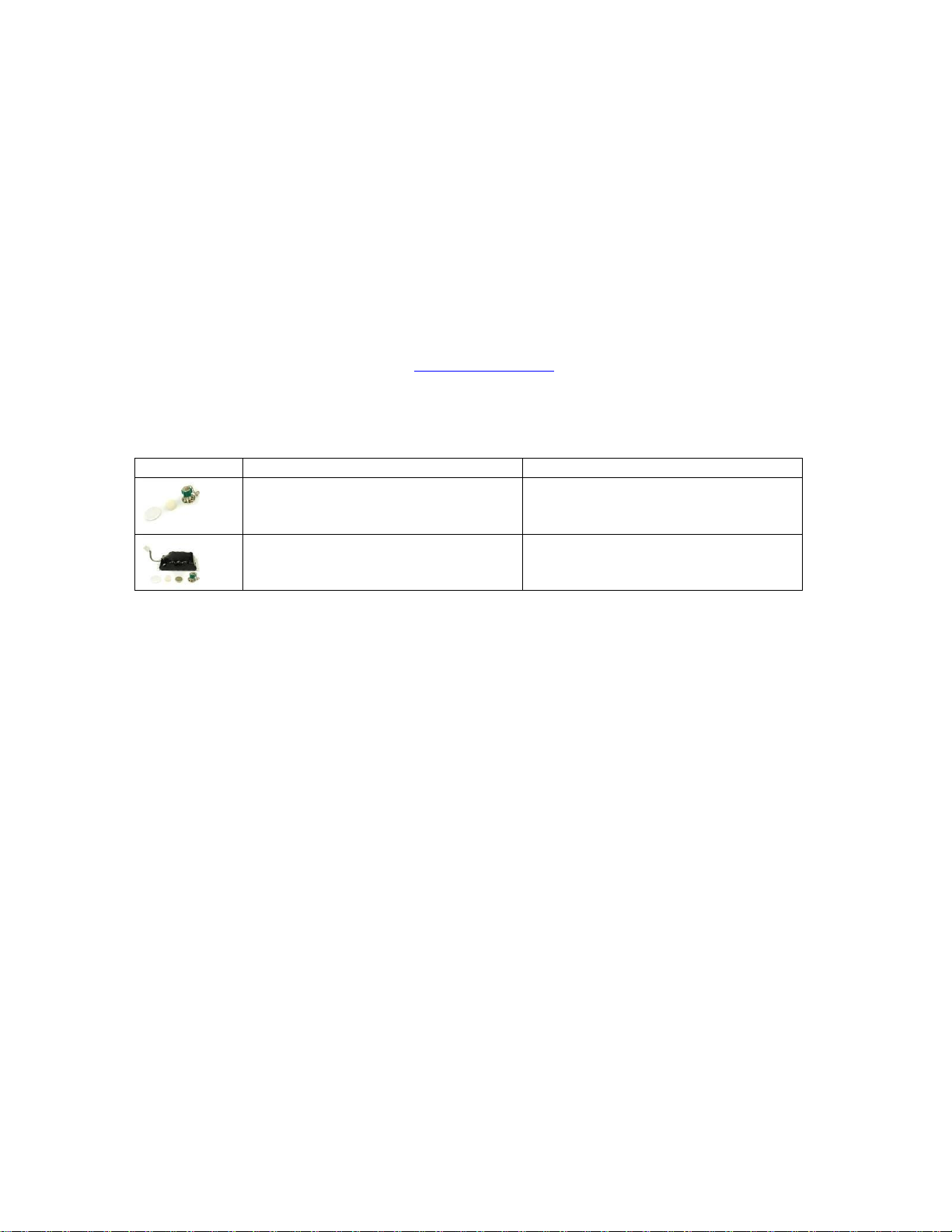
Picture
Description
Kit #
Annual Preventive Maintenance Kit
712-0731-20
4-Year Preventive Maintenance Kit
712-0731-21
should also be performed whenever the operator suspects that the device is not functioning properly or
following mass deployment and before the device is returned to storage. If the device fails the PMC it
should be maintained by a certified Impact service technician in the field or at Impact authorized service
locations. A secure record of PMC results should be maintained for devices not returned to Impact for
maintenance.
Impact’s 731 series service tool the RCS is needed to perform the PMC and reset the ‘performance
maintenance check’ low priority alarm. This tool includes can be purchased from Impact for use by Impact
trained and certified biomedical technicians. Alternatively, 731 series can be sent to an Impact authorized
service center for PMC or other service requirements.
In addition to automating and documenting the PMC process, the RCS is also capable of calibrating the
device and installing and verifying software upgrades and updates to the 731 series of devices.
If you would like to return the ventilator to Impact for service please contact Impact prior to returning this
instrument. (Telephone 973.882.1212, email service@impactii.com). A Returned-Goods-Authorization
number (RGA #) will be issued. The RGA # must appear on both the packing slip and address label. This will
facilitate better tracking of the returned item and result in improved scheduling and handling.
Annual and 4-Year PM Kits are available to trained personnel and service centers.
906-0731-04 Rev. B Sept. 2012 Page 14 of 68
Page 15
Troubleshooting and Repairs
The device uses a comprehensive suite of alarms to alert the operator and guide their actions to resolve the
alarm condition and assure patient safety. At the onset of an alarm, the screen displays the alarm name and
then a series of context-sensitive help messages (see Figure 2 example). These messages serve to guide the
operator by presenting suggestions as to the cause and resolution of a particular alarm. When multiple
alarms occur they are prioritized and displayed based on the risk to the patient. Should the operator not be
able to correct the problem, the ventilator should be taken out of use and sent to an authorized Impact
repair facility.
Trained bio-med technicians are encouraged to use a systematic approach to solving issues with the
ventilator. Use the Alarm Category and Service Code matrices listed in Appendix to resolve the problem or
to identify the suggested replacement service kit. Check on-hand availability or order the kit(s) from Impact,
then follow the detailed instructions listed to replace the kit. Trained repair facilities can contact Impact’s
technical service department via email: service @impactii.com or by telephone toll free: 800-969-0750 or
973-882-1212 for troubleshooting and repair recommendations.
ALARM & PLOT LIST: FIGURE 2
Service Kits
Service kits, which are preassembled and factory tested subassemblies, are available should physical
damage or problems of an unforeseen nature arise. Service kits are available only to qualified trained
biomedical personnel or authorized Impact service centers. Each kit replacement must be followed by a
HiPot test (See section titled HiPot Testing ), then either by a functional test or a calibration and functional
test using the Remote Calibration System (RCS).The following table lists the kits for each 731 series model.
906-0731-04 Rev. B Sept. 2012 Page 15 of 68
Page 16

Service Kit Listing
Description
EMVP
Eagle II
Picture
Kit #
Picture
Kit#
Membrane Panel Kit
712-0731-01
712-EGL2-01
SPM/Vent Assembly Kit
712-0731-02
712-EGL2-02
Battery Compartment Kit
712-0731-03
712-EGL2-03
712-EGL2-13 (MR)
Outer Air Intake Kit
712-0731-04
712-EGL2-04
Bezel Assembly Kit
712-0731-05 (EMVP)
712-AEV1-01 (AEV)
712-EGL2-05
Power Knob Kit
712-0731-06
712-EGL2-06
USB Connector Plate Kit
712-0731-07
712-EGL2-07
Front Case Assembly Kit
712-0731-08 (EMVP)
712-AEV1-02 (AEV)
712-EGL2-08
Battery Case Bottom Cover Kit
712-0731-09
712-EGL2-08
EMV Chassis Kit
712-0731-10
712-EGL2-10
Connector Panel Kit
712-0731-11
712-EGL2-11
Back Case Kit
712-0731-12
712-EGL2-12
PIM Board Kit
702-0731-02
702-0731-02
CPU/UIM & SPO2 Stack Kit
712-0731-14
712-0731-14
USB Connector Kit
712-0731-15
712-0731-15
Gas Output Kit
712-0731-16
712-0731-16
Power Input Kit
712-0731-17
712-0731-17
Oxygen Inlet Fitting Kit
712-0731-18
712-0731-18
Selector Knob Kit
712-0731-19
392-0066-00
906-0731-04 Rev. B Sept. 2012 Page 16 of 68
Page 17
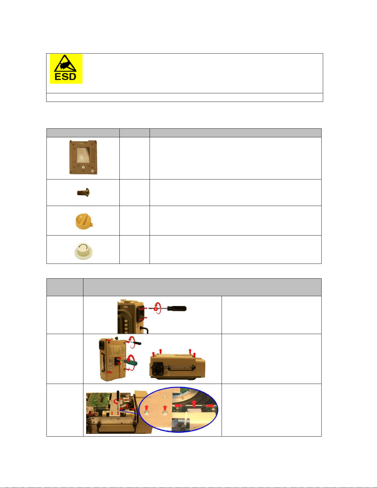
Replacement Instructions
STEP NO.
DIRECTIONS
1
Loosen but do not remove the
(4) 8-32 X 3 screws on the outer air
intake.
2
Loosen and remove the (2) 10-32
Keps nuts and the (4) 6-32 X 2
screws. Remove the back case by
lifting from the ventilator.
3
Remove the (2) 4-40 X ¼ screws on
the Dovetail Mounting Bracket and
disconnect the ribbon cable on the
PIM PCB by simultaneously applying
pressure on the two locking “ears”.
ITEM
QTY
DESCRIPTION
1
Membrane Panel Assembly
7
Screw, Phillips, Pan Head, Zinc Plated, 4-40 X 1/4
1
Power Select Knob with Set screw
1
Selector Knob
CAUTION! Internal components are susceptible to damage from static discharge. All servicing
operations MUST be done in an ESD controlled environment.
CAUTION! Disconnect external power and battery pack prior to performing any service.
Membrane Panel Kit 712-0731-01 / 712-EGL2-01
Contents:
Instructions:
906-0731-04 Rev. B Sept. 2012 Page 17 of 68
Page 18

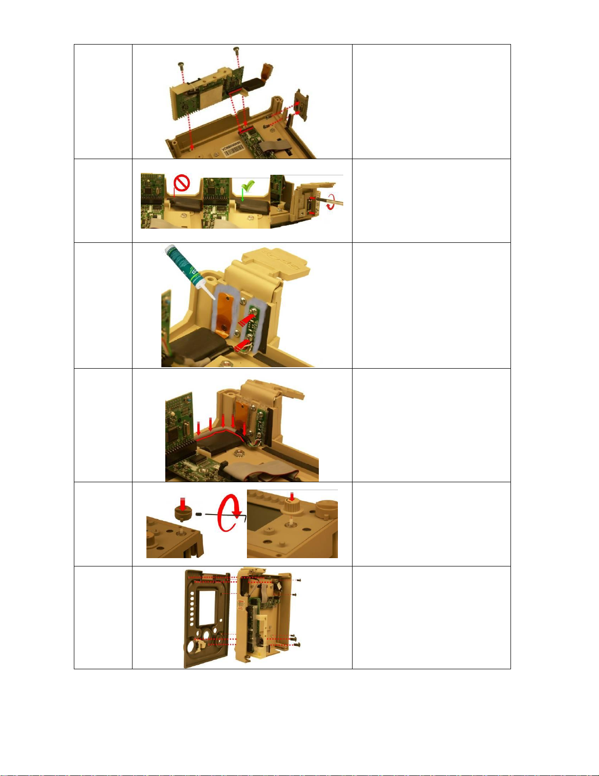
4
Flip the ventilator over and remove
the front case assembly by lifting it
straight up away from the ventilator
module.
5
Remove the bezel by loosening and
removing the (7) 4-40 X ¼ screws
that hold the bezel to the front case.
6
Using a sharp knife, carefully cut the
RTV sealant around the USB Printed
Circuit Board and around the SPO2
Connector. Be careful not to cut
either cable.
7
Loosen and remove the two 4-40 X
3/16 screws holding the Mini USB
Cable Assembly to the front case.
Loosen and remove the two M2.5 X
5mm screws holding the SPO2 cable
to the front case.
8
Loosen and remove the two (2)
6-32 X 5/16 screws that hold the
CPU/UIM & SPO2 Stack to the front
case.
9
Lift the CPU/UIM & SPO2 Stack up
from the front case. Handle the
SPO2 cable with extreme care. Do
not pull on the cable.
10
Loosen and remove the two 4-40 X
5/16 screws holding the USB
Connector Plate to the front case.
906-0731-04 Rev. B Sept. 2012 Page 18 of 68
Page 19
11
Tighten the two 4-40 X 5/16 screws
holding the USB Connector Plate to
the replacement front case. Tighten
the two (2) 6-32 X 5/16 screws that
hold the CPU/UIM & SPO2 Stack to
the front case. Make sure that all the
pins on the header mate correctly.
12
Make sure the SPO2 Flex Cable lays
flat against the front case and is
assembled correctly into the UIM
Bracket and SPO2 Isolation Shield.
Insert and tighten the two M2.5 X
5mm screws holding the SPO2 cable
to the front case.
13
Remove any excess RTV sealant from
the SPO2 flex cable and USB PCB.
Tighten the two 4-40 X 3/16 screws
holding the USB PCB to the front
case. Apply RTV sealant to USB PCB
and SPO2 flex cable. Allow to
dry/cure.
14
Dress the USB Connector cable along
the case and over the SPO2 flex
cable.
15
Place the included power knob on
the new membrane panel switch -
align with flat on switch – insert the
included 6-32 X ¼ set screw and
tighten. Push the included selector
knob on the membrane panel switch
- align with flat on switch .
16
Place the front case assembly on to
the bezel and tighten the included
(7) 4-40 X ¼ screws.
906-0731-04 Rev. B Sept. 2012 Page 19 of 68
Page 20
17
Place the front case assembly over
the vent module and tighten the (2)
4-40 X ¼ screws unto the dovetail
mounting bracket. Reconnect the
ribbon cable unto the PIM PCB.
Make sure the two locking “ears”
lock into position.
18
Attach the back case to the vent
module and align cover with handle,
air intake housing and dovetail
mounting studs. Insert and tighten
the included (2) 10-32 Keps nuts and
the (4) 6-32 X 2” screws.
19
Tighten the (4) 8-32 X 3 screws on
the outer air intake.
20
Perform HiPot Testing then perform
Calibration and Functional Test using
the RCS.
906-0731-04 Rev. B Sept. 2012 Page 20 of 68
Page 21
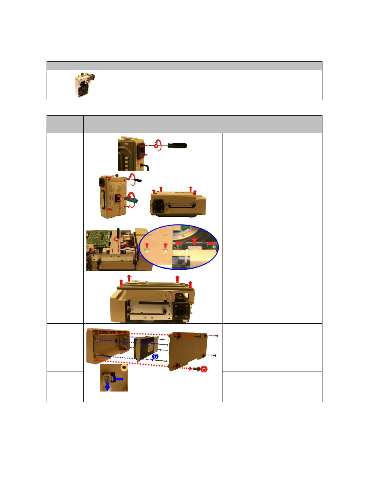
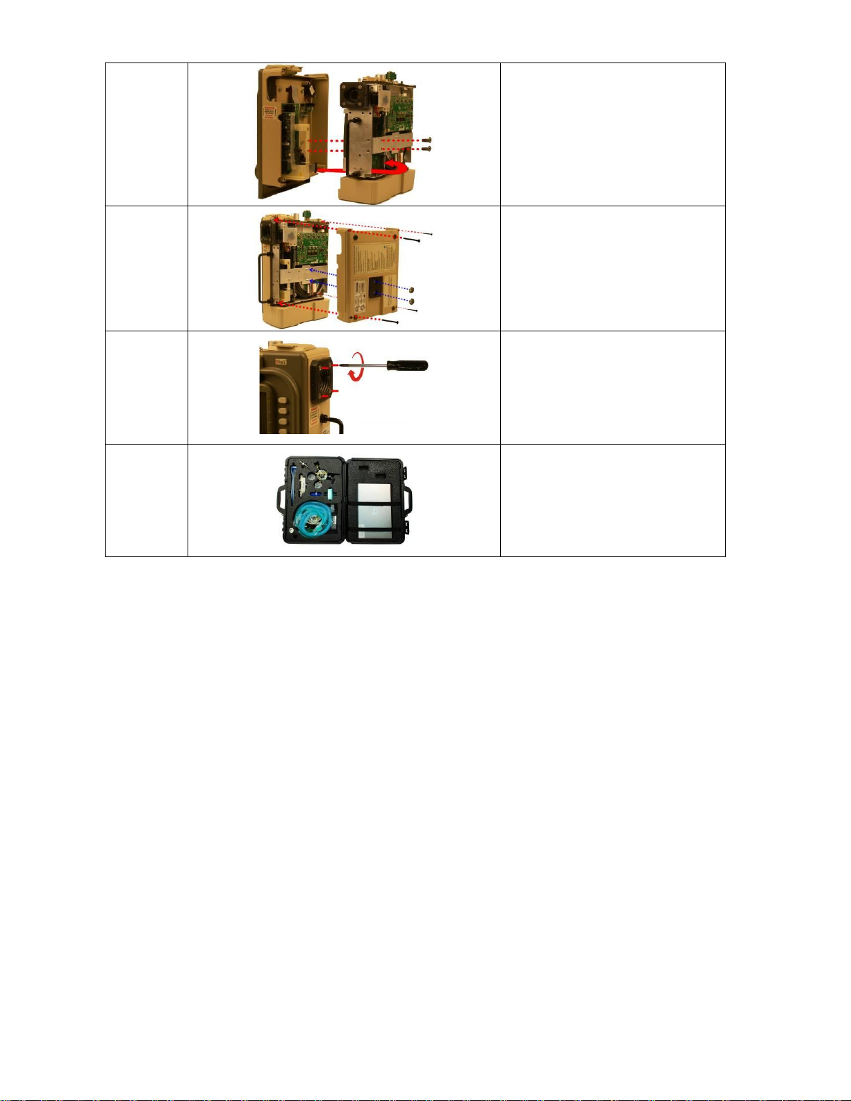
SPM Kit 712-0731-02 / 712-EGL2-02
STEP NO.
DIRECTIONS
1
Loosen but do not remove the
(4) 8-32 X 3 screws on the outer air
intake.
2
Loosen and remove the (2) 10-32
Keps nuts and the (4) 6-32 X 2
screws. Remove the back case by
lifting from the ventilator.
3
Remove the (2) 4-40 X ¼ screws on
the Dovetail Mounting Bracket and
disconnect the ribbon cable on the
PIM PCB by simultaneously applying
pressure on the two locking “ears”.
4
Flip the ventilator over and remove
the front case assembly by lifting it
straight up away from the ventilator
module.
5
Remove the battery compartment
cover by unscrewing the (4) 6-32 X
5/16 screws.
6
Remove the battery by unscrewing
the (4) 6-32 X 2 ¼ screws and
detaching the plug from its locking
latch.
ITEM
QTY
DESCRIPTION
1
SPM/Vent Assembly
Contents:
Instructions:
906-0731-04 Rev. B Sept. 2012 Page 21 of 68
Page 22

7
Unscrew the (4) 6-32 X 5/16 Phillips
screws to remove the damaged battery
compartment case.
8
Loosen and remove the (2) 4-40 X 1 ¼
Screws and nylon spacers supporting the
Power Input assembly unto the chassis.
9
Loosen and remove the (2) 6-32 X ¼
screws holding the chassis to the dovetail
mounting bracket and remove the SPO2
insulator. Loosen and remove the (2) 8-
32 X ¼ screws holding the chassis to the
vent module.
10
Insert screwdriver through the holes on
the chassis to loosen and remove the (2)
6-32 x 5/16 screws holding the chassis to
the vent module.
11
Lift the damaged chassis from the
ventilator module.
12
Disconnect the Power Input cable from
the PIM PCB by pressing on the locking
latch and pulling the cable straight up
from the connector.
13
Remove the PIM PCB by loosening the (5)
4-40 X 5/16 screws.
906-0731-04 Rev. B Sept. 2012 Page 22 of 68
Page 23

14
Remove the Dovetail stabilizer bracket by
loosening and removing the (2) 6-32 x ¼
and the (2) 4-40 X ¼ screws.
15
Install the dovetail stabilizer bracket onto
the new SPM assembly by tightening the
(2) 6-32 X ¼ and (2) 4-40 X ¼ screws.
16
Secure the PIM Board to the new SPM
with the (5) 4-40 x 5/16 screws.
17
Secure the chassis to the vent module
using the (2) 6-32 X ¼ screws with SPO2
insulator, the (2) 8-32 X ¼ and the (2) 6-
32 x 5/16 screws.
18
Secure the Power Input assembly to the
Chassis using the (2) spacers and (2) 4-40
X 1 ¼ screws. Do not over-tighten the
screws.
906-0731-04 Rev. B Sept. 2012 Page 23 of 68
Page 24

19
Rotate battery compartment to mate
with upper and lower case cutouts and
press firmly into place. Secure with (4) 6-
32 X 5/16 screws provided.
20
Re-assemble the battery by connecting
its cable to the connector (pull on cable
to insure it is locked in place) then
tightening the (4) 6-32 X 2 ¼ screws.
21
Re-assemble the battery compartment
cover by tightening the (4) 6-32 X 5/16
screws.
22
Place the front case assembly over the
vent module and tighten the (2) 4-40 X ¼
screws unto the dovetail mounting
bracket. Reconnect the ribbon cable unto
the PIM PCB. Make sure the two locking
“ears” lock into position.
23
Attach the back case to the vent module
and align cover with handle, air intake
housing and dovetail mounting studs.
Insert and tighten the included (2) 10-32
Keps nuts and the (4) 6-32 X 2” screws.
24
Tighten the (4) 8-32 X 3 screws on the
outer air intake.
25
Perform HiPot Testing then perform
Calibration and Functional Test using the
RCS.
906-0731-04 Rev. B Sept. 2012 Page 24 of 68
Page 25

Battery Compartment Kit 712-0731-03 / 712-EGL2-03
Step No.
Directions
1
Remove the battery
compartment cover by
unscrewing the (4) 6-32 X 5/16
screws.
2
Remove the battery by
unscrewing the (4) 6-32 X 2 ¼
screws and detaching the plug
from its locking latch.
3
Unscrew the (4) 6-32 X 5/16
Phillips screws to remove the
damaged battery compartment
case.
4
Rotate battery compartment to
mate with upper and lower case
cutouts and press firmly into
place. Secure with (4) 6-32 X
5/16 screws provided.
5
Re-assemble the battery by
connecting its cable to the
connector (pull on cable to
insure it is locked in place) then
tightening the (4) 6-32 X 2 ¼
screws.
6
Re-assemble the battery
compartment cover by tightening
the (4) 6-32 X 5/16 screws.
7
Perform HiPot Testing then
perform Functional Test using
the RCS.
ITEM
QTY
DESCRIPTION
1
Battery Compartment Case with Gaskets
4
Screw, Phillips, Pan Head, SS, 6-32 X 5/16
Contents:
Instructions:
906-0731-04 Rev. B Sept. 2012 Page 25 of 68
Page 26

Outer Air Intake Kit 712-0731-04 / 712-EGL2-04
STEP NO.
DIRECTIONS
1
Remove the damaged Outer Air Intake by
unscrewing the (4) 8-32 X 3 screws.
2
The O-Ring is pre-installed into the groove on
40mm Adapter. Verify it is inserted correctly.
3
Place Intake Plate over 40mm Adapter and the 4
8-32 X 3 screws through Intake Plate and 40mm
Adapter.
4
Rotate assembly such that the alignment pin on
the BV Filter Holder mates with the alignment
hole on the 40mm Adapter.
5
Place entire assembly into BV Filter Holder and
tighten the included (4) 8-32 X 3 screws.
6
Perform HiPot Testing then perform Calibration
and Functional Test using the RCS.
ITEM
QTY
DESCRIPTION
1
Plate, Intake
4
Screw, PFH, SS, 8-32 X 3
1
Adapter, 40mm with O-Ring
1
O-Ring, Buna, 2-3/8X2.5X1/16" (Pre-installed into 40mm adapter)
Contents:
Instructions:
906-0731-04 Rev. B Sept. 2012 Page 26 of 68
Page 27

Bezel Assembly Kit 712-0731-05 / 712-EGL2-05 / 712-AEV1-01
STEP NO.
DIRECTIONS
1
Loosen but do not remove the
(4) 8-32 X 3 screws on the outer air intake.
2
Loosen and remove the (2) 10-32 Keps nuts
and the (4) 6-32 X 2 screws. Remove the
back case by lifting from the ventilator.
3
Remove the (2) 4-40 X ¼ screws on the
Dovetail Mounting Bracket and disconnect
the ribbon cable on the PIM PCB by
simultaneously applying pressure on the
two locking “ears”.
4
Flip the ventilator over and remove the
front case assembly by lifting it straight up
away from the ventilator module.
ITEM
QTY
DESCRIPTION
1
Bezel Assembly
7
Screw, Phillips, Pan Head, Zinc Plated, 4-40 X 1/4
1
EMV Label
1
EMVP Label
Contents:
Instructions:
906-0731-04 Rev. B Sept. 2012 Page 27 of 68
Page 28

5
Remove the bezel by loosening and
removing the (7) 4-40 X ¼ screws that hold
the bezel to the front case.
6
Select the correct label for your device,
peel the backing off and affix to the front
bezel.
7
Install the new bezel by tightening the
included (7) 4-40 X ¼ screws.
8
Place the front case assembly over the vent
module and tighten the (2) 4-40 X ¼ screws
unto the dovetail mounting bracket.
Reconnect the ribbon cable unto the PIM
PCB. Make sure the two locking “ears” lock
into position.
9
Attach the back case to the vent module
and align cover with handle, air intake
housing and dovetail mounting studs.
Insert and tighten the included (2) 10-32
Keps nuts and the (4) 6-32 X 2” screws.
10
Tighten the (4) 8-32 X 3 screws on the
outer air intake.
11
Perform HiPot Testing then perform
Functional Test using the RCS.
906-0731-04 Rev. B Sept. 2012 Page 28 of 68
Page 29

Power Knob Kit 712-0731-06 / 712-EGL2-06
STEP NO.
DIRECTIONS
1
Loosen but do not remove the
(4) 8-32 X 3 screws on the outer air intake.
2
Loosen and remove the (2) 10-32 Keps nuts
and the (4) 6-32 X 2 screws. Remove the
back case by lifting from the ventilator.
3
Remove the (2) 4-40 X ¼ screws on the
Dovetail Mounting Bracket and disconnect
the ribbon cable on the PIM PCB by
simultaneously applying pressure on the
two locking “ears”.
4
Flip the ventilator over and remove the
front case assembly by lifting it straight up
away from the ventilator module.
5
Remove the bezel by loosening and
removing the (7) 4-40 X ¼ screws that hold
the bezel to the front case.
ITEM
QTY
DESCRIPTION
1
Power Knob
1
Screw, Socket, Cup Point, Set, 6-32 X 1/4 (installed into knob)
Contents:
Instructions:
906-0731-04 Rev. B Sept. 2012 Page 29 of 68
Page 30

6
On the membrane panel assembly, loosen
the 6-32 X ¼ set screw using a 1/16 Ball Hex
Driver (located in the power knob) and lift
the damaged knob from the membrane
panel.
7
Place the replacement knob on the
membrane panel switch - align with flat on
switch – insert the included 6-32 X ¼ set
screw and tighten.
8
Install the new bezel by tightening the
included (7) 4-40 X ¼ screws.
9
Place the front case assembly over the vent
module and tighten the (2) 4-40 X ¼ screws
unto the dovetail mounting bracket.
Reconnect the ribbon cable unto the PIM
PCB. Make sure the two locking “ears” lock
into position.
10
Attach the back case to the vent module
and align cover with handle, air intake
housing and dovetail mounting studs.
Insert and tighten the included (2) 10-32
Keps nuts and the (4) 6-32 X 2” screws.
11
Tighten the (4) 8-32 X 3 screws on the
outer air intake.
12
Perform HiPot Testing then perform
Calibration and Functional Test using the
RCS.
906-0731-04 Rev. B Sept. 2012 Page 30 of 68
Page 31

USB Connector Plate Kit 712-0731-07 / 712-EGL2-07
STEP NO.
DIRECTIONS
1
Loosen but do not remove the
(4) 8-32 X 3 screws on the outer air
intake.
2
Loosen and remove the (2) 10-32 Keps
nuts and the (4) 6-32 X 2 screws.
Remove the back case by lifting from
the ventilator.
3
Remove the (2) 4-40 X ¼ screws on
the Dovetail Mounting Bracket and
disconnect the ribbon cable on the
PIM PCB by simultaneously applying
pressure on the two locking “ears”.
4
Flip the ventilator over and remove
the front case assembly by lifting it
straight up away from the ventilator
module.
5
Remove the bezel by loosening and
removing the (7) 4-40 X ¼ screws that
hold the bezel to the front case.
ITEM
QTY
DESCRIPTION
1
USB Connector Plate Assembly
2
Screw, Phillips, Pan Head, Zinc Plated, 4-40 X 5/16
Contents:
Instructions:
906-0731-04 Rev. B Sept. 2012 Page 31 of 68
Page 32

6
Using a sharp knife, carefully cut the
RTV sealant around the USB Printed
Circuit Board and around the SPO2
Connector. Be careful not to cut either
cable.
7
Loosen and remove the two 4-40 X
3/16 screws holding the Mini USB
Cable Assembly to the front case.
Loosen and remove the two M2.5 X
5mm screws holding the SPO2 cable
to the front case.
8
Loosen and remove the two (2)
6-32 X 5/16 screws that hold the
CPU/UIM & SPO2 Stack to the front
case.
9
Lift the CPU/UIM & SPO2 Stack up
from the front case. Handle the SPO2
cable with extreme care. Do not pull
on the cable.
10
Loosen and remove the two 4-40 X
5/16 screws holding the damaged USB
Connector Plate to the front case.
11
Insert and tighten the two included 4-
40 X 5/16 screws holding the
replacement USB Connector Plate to
the front case.
12
Tighten the two (2) 6-32 X 5/16 screws
that hold the CPU/UIM & SPO2 Stack
to the front case. Make sure that all
the pins on the header mate correctly.
906-0731-04 Rev. B Sept. 2012 Page 32 of 68
Page 33

13
Make sure the SPO2 Flex Cable lays
flat against the front case and is
assembled correctly into the UIM
Bracket and SPO2 Isolation Shield.
Insert and tighten the two M2.5 X
5mm screws holding the SPO2 cable
to the front case.
14
Remove any excess RTV sealant from
the SPO2 flex cable and USB PCB.
Tighten the two 4-40 X 3/16 screws
holding the USB PCB to the front case.
Apply RTV sealant to USB PCB and
SPO2 flex cable. Allow to dry/cure.
15
Place the included power knob on the
new membrane panel switch - align
with flat on switch – insert the
included 6-32 X ¼ set screw and
tighten. Push the included selector
knob on the membrane panel switch -
align with flat on switch .
16
Place the front case assembly on to
the bezel and tighten the included (7)
4-40 X ¼ screws.
17
Place the front case assembly over the
vent module and tighten the (2) 4-40
X ¼ screws unto the dovetail
mounting bracket. Reconnect the
ribbon cable unto the PIM PCB. Make
sure the two locking “ears” lock into
position.
18
Attach the back case to the vent
module and align cover with handle,
air intake housing and dovetail
mounting studs. Insert and tighten the
included (2) 10-32 Keps nuts and the
(4) 6-32 X 2” screws.
19
Tighten the (4) 8-32 X 3 screws on the
outer air intake.
20
Perform HiPot Testing then perform
Calibration and Functional Test using
the RCS.
906-0731-04 Rev. B Sept. 2012 Page 33 of 68
Page 34

Front Case Assembly Kit 712-0731-08 / 712-EGL2-08 / 712-AEV1-02
STEP NO.
DIRECTIONS
1
Loosen but do not remove the
(4) 8-32 X 3 screws on the outer air
intake.
2
Loosen and remove the (2) 10-32 Keps
nuts and the (4) 6-32 X 2 screws.
Remove the back case by lifting from
the ventilator.
3
Remove the (2) 4-40 X ¼ screws on
the Dovetail Mounting Bracket and
disconnect the ribbon cable on the
PIM PCB by simultaneously applying
pressure on the two locking “ears”.
4
Flip the ventilator over and remove
the damaged front case assembly by
lifting it straight up away from the
ventilator module.
ITEM
QTY
DESCRIPTION
1
Front Case Assembly
2
Screw, Phillips, Pan Head, Zinc Plated, 4-40 X 1/4
1
EMV Label
1
EMVP Label
Contents:
Instructions:
WARNING: Disconnect external power and battery pack prior to performing service.
906-0731-04 Rev. B Sept. 2012 Page 34 of 68
Page 35

5
Place the replacement front case
assembly over the vent module and
tighten the (2) 4-40 X ¼ screws unto
the dovetail mounting bracket.
Reconnect the ribbon cable unto the
PIM PCB. Make sure the two locking
“ears” lock into position.
6
Attach the back case to the vent
module and align cover with handle,
air intake housing and dovetail
mounting studs. Insert and tighten the
included (2) 10-32 Keps nuts and the
(4) 6-32 X 2” screws.
7
Tighten the (4) 8-32 X 3 screws on the
outer air intake.
8
Select the correct label for your
device, peel the backing off and affix
to the front bezel.
9
Update serial numbers using
the RCS:
a. Use the “C:\program
files\impact\EMV\bin\
EmvDLGui.exe” to change
the serial numbers.
b. Use the RCS FD app to re-
flash the firmware.
10
Perform HiPot Testing then perform
Calibration and Functional Test using
the RCS.
906-0731-04 Rev. B Sept. 2012 Page 35 of 68
Page 36

Battery Case Bottom Cover Kit 712-0731-09 / 712-EGL2-09
STEP NO.
DIRECTIONS
1
Remove the damaged cover by unscrewing
the (4) 6-32 X 5/16 screws.
2
Remove backing from Bumper feet and place
one at each corner of Battery case bottom
cover.
3
Rotate cover to align with battery
compartment then insert and tighten the (4)
6-32 X 5/16 screws.
4
Perform HiPot Testing then perform
Functional Test using the RCS.
ITEM
QTY
DESCRIPTION
1
Battery case bottom cover
4
Screw, Phillips, Pan Head, SS, 6-32 X 5/16
4
Bumper, Rubber, Foot, P/S, Round, 1/2" Dia. X 1/8", Blk
Contents:
Instructions:
906-0731-04 Rev. B Sept. 2012 Page 36 of 68
Page 37

EMV Chassis Kit 712-0731-10 / 712-EGL2-10
STEP NO.
DIRECTIONS
1
Loosen but do not remove the
(4) 8-32 X 3 screws on the outer air
intake.
2
Loosen and remove the (2) 10-32 Keps
nuts and the (4) 6-32 X 2 screws.
Remove the back case by lifting from
the ventilator.
3
Remove the (2) 4-40 X ¼ screws on
the Dovetail Mounting Bracket and
disconnect the ribbon cable on the
PIM PCB by simultaneously applying
pressure on the two locking “ears”.
4
Flip the ventilator over and remove
the front case assembly by lifting it
straight up away from the ventilator
module.
ITEM
QTY
DESCRIPTION
1
EMV Chassis Assembly
2
Screw, Phillips, Pan Head, SS, 6-32 X 5/16
2
Screw, Phillips, Flat Head, 8-32 X 1/4, Undercut, ZP
2
Screw, Phillips, Flat Head, 6-32 X 1/4, Undercut
1
SPO2 Insulator
Contents:
Instructions:
906-0731-04 Rev. B Sept. 2012 Page 37 of 68
Page 38

5
Remove the battery compartment cover
by unscrewing the (4) 6-32 X 5/16
screws.
6
Remove the battery by unscrewing the
(4) 6-32 X 2 ¼ screws and detaching the
plug from its locking latch.
7
Unscrew the (4) 6-32 X 5/16 Phillips
screws to remove the damaged battery
compartment case.
8
Loosen and remove the (2) 4-40 X 1 ¼
Screws and nylon spacers supporting the
Power Input assembly unto the chassis.
9
Loosen and remove the (2) 6-32 X ¼
screws holding the chassis to the dovetail
mounting bracket and remove the SPO2
insulator. Loosen and remove the (2) 8-
32 X ¼ screws holding the chassis to the
vent module.
10
Insert screwdriver through the holes on
the chassis to loosen and remove the (2)
6-32 x 5/16 screws holding the chassis to
the vent module.
11
Lift the damaged chassis from the
ventilator module.
906-0731-04 Rev. B Sept. 2012 Page 38 of 68
Page 39

12
Secure the replacement Chassis to the
vent module using the included (2) 6-32 X
¼ screws with SPO2 insulator, the (2) 8-
32 X ¼ and the (2) 6-32 x 5/16 screws.
13
Secure the Power Input assembly to the
Chassis using the (2) spacers and (2) 4-40
X 1 ¼ screws. Do not over-tighten the
screws.
14
Rotate battery compartment to mate
with upper and lower case cutouts and
press firmly into place. Secure with (4) 6-
32 X 5/16 screws provided.
15
Re-assemble the battery by connecting
its cable to the connector (pull on cable
to insure it is locked in place) then
tightening the (4) 6-32 X 2 ¼ screws.
16
Re-assemble the battery compartment
cover by tightening the (4) 6-32 X 5/16
screws.
17
Place the front case assembly over the
vent module and tighten the (2) 4-40 X ¼
screws unto the dovetail mounting
bracket. Reconnect the ribbon cable unto
the PIM PCB. Make sure the two locking
“ears” lock into position.
906-0731-04 Rev. B Sept. 2012 Page 39 of 68
Page 40

18
Attach the back case to the vent module
and align cover with handle, air intake
housing and dovetail mounting studs.
Insert and tighten the included (2) 10-32
Keps nuts and the (4) 6-32 X 2” screws.
19
Tighten the (4) 8-32 X 3 screws on the
outer air intake.
20
Perform HiPot Testing then perform
Calibration and Functional Test using the
RCS.
906-0731-04 Rev. B Sept. 2012 Page 40 of 68
Page 41

Connector Panel Kit 712-0731-11 / 712-EGL2-11
STEP NO.
DIRECTIONS
1
Loosen but do not remove the
(4) 8-32 X 3 screws on the outer air
intake.
2
Loosen and remove the (2) 10-32 Keps
nuts and the (4) 6-32 X 2 screws.
Remove the back case by lifting from
the ventilator.
3
Remove the (2) 4-40 X ¼ screws on
the Dovetail Mounting Bracket and
disconnect the ribbon cable on the
PIM PCB by simultaneously applying
pressure on the two locking “ears”.
4
Flip the ventilator over and remove
the front case assembly by lifting it
straight up away from the ventilator
module.
ITEM
QTY
DESCRIPTION
1
Connector Panel Assembly
3
8-32 X 1/4 Screw
4
6-32 Keps Nut
2
O-Ring ½” OD X 3/8” ID
Contents:
Instructions:
906-0731-04 Rev. B Sept. 2012 Page 41 of 68
Page 42

5
Remove the O2 Inlet fitting by
unscrewing the dust cap then unscrewing
the (3) 8-32 X 7/16 screws.
6
Loosen and remove the (3) 8-32 X ¼
screws. Loosen and remove the Gas
Output fitting using a 1-inch deep-socket
wrench.
7
Disconnect the Power Input cable by
pressing on the locking latch and pulling
the cable straight up from the connector.
8
Loosen and remove the (2) 4-40 X 1 ¼
Screws and nylon spacers supporting the
Power Input assembly unto the chassis.
9
Loosen and remove the (2) 6-32 Keps
nuts using a 5/16 open-end wrench.
10
Using a needle nose pliers, carefully
remove the 3 tubing on the
“Transducer”, “Exhaust Do not Occlude”,
and “Exhalation Valve” fittings.
11
Loosen and remove the (2) 6-32 Keps
nuts using a 5/16 open-end wrench.
906-0731-04 Rev. B Sept. 2012 Page 42 of 68
Page 43

12
Lift the damaged connector panel
assembly out from the SPM.
13
Place the included ½” OD X 3/8” ID O-ring
onto the manifold.
14
Position the replacement Connector
Panel over the SPM and secure with the
(4) included 6-32 Keps nuts.
15
Secure the Power Input assembly to the
Chassis using the (2) spacers and (2) 4-40
X 1 ¼ screws. Do not over-tighten the
screws. Connect the Power Input cable
by inserting into connector. Insure that
locking latch engages.
16
Insert the 3 tubing unto their correct
connectors. “V_BACKUP” to “Exhalation
Valve”, V_ACAL” to “Transducer” and
smallest tubing to “Exhaust do Not
occlude”
17
Secure the connector panel to the vent
module using the (3) included 8-32 X ¼
screws.
18
Insert the included 3/8” ID O-Ring unto
the Oxygen Inlet fitting and the existing
1/2” ID O-ring unto the Gas Output
adapter.
906-0731-04 Rev. B Sept. 2012 Page 43 of 68
Page 44

19
Place Oxygen Inlet Fitting over the
connector panel then insert and tighten
with the (3)8-32 X 7/16 screws.
Place fitting and O-ring unto Gas Output
and tighten with a 1” deep socket
wrench. (Do not cross thread).
20
Place the front case assembly over the
vent module and tighten the (2) 4-40 X ¼
screws unto the dovetail mounting
bracket. Reconnect the ribbon cable unto
the PIM PCB. Make sure the two locking
“ears” lock into position.
21
Attach the back case to the vent module
and align cover with handle, air intake
housing and dovetail mounting studs.
Insert and tighten the included (2) 10-32
Keps nuts and the (4) 6-32 X 2” screws.
22
Tighten the (4) 8-32 X 3 screws on the
outer air intake.
23
Perform HiPot Testing then perform
Calibration and Functional Test using the
RCS.
906-0731-04 Rev. B Sept. 2012 Page 44 of 68
Page 45

Back Case Kit 712-0731-12 / 712-EGL2-12
STEP NO.
DIRECTIONS
1
Loosen but do not remove the
(4) 8-32 X 3 screws on the outer air intake.
2
Loosen and remove the (2) 10-32 Keps nuts
and the (4) 6-32 X 2 screws. Remove the
case by lifting from the ventilator.
3
Place the replacement cover over ventilator
and align cover with handle, air intake
housing and dovetail mounting studs. Insert
and tighten the included (2) 10-32 Keps nuts
and the (4) 6-32 X 2” screws.
4
Tighten the (4) 8-32 X 3 screws on the outer
air intake.
5
Perform HiPot Testing then perform
Functional Test using the RCS.
ITEM
QTY
DESCRIPTION
1
Back Case Assembly
4
Screw, Phillips, Pan Head, SS, Black Oxide, 6-32 X 2
2
Nut, Keps, 10-32
Contents:
Instructions:
906-0731-04 Rev. B Sept. 2012 Page 45 of 68
Page 46

PIM Board Kit 702-0731-02
STEP NO.
DIRECTIONS
1
Loosen but do not remove the
(4) 8-32 X 3 screws on the outer
air intake.
2
Loosen and remove the (2) 10-
32 Keps nuts and the (4) 6-32 X
2 screws. Remove the back case
by lifting from the ventilator.
3
Remove the (2) 4-40 X ¼ screws
on the Dovetail Mounting
Bracket and disconnect the
ribbon cable on the PIM PCB by
simultaneously applying
pressure on the two locking
“ears”.
4
Flip the ventilator over and
remove the front case assembly
by lifting it straight up away
from the ventilator module.
5
Remove the battery
compartment cover by
unscrewing the (4) 6-32 X 5/16
screws.
6
Remove the battery by
unscrewing the (4) 6-32 X 2 ¼
screws and detaching the plug
from its locking latch.
7
Disconnect the Power Input
cable from the PIM PCB by
pressing on the locking latch and
pulling the cable straight up
from the connector.
ITEM
QTY
DESCRIPTION
1
PIM PCB
Contents:
Instructions:
906-0731-04 Rev. B Sept. 2012 Page 46 of 68
Page 47

8
Loosen and remove the(5) 4-40
X 5/16 screws holding the PIM
PCB to the ventilator module.
Position SPO2 Insulator out of
the way (Do Not Fold) and insert
screwdriver through the holes
to aid in removing screws.
9
Lift the defective PIM Board out
of the ventilator module.
10
Place the new PIM Board
Unto the vent module (make
sure male header pins are
inserted correctly into the
mating header.
11
Secure the PIM Board with the
(5) 4-40 x 5/16 screws.
12
Re-assemble the battery by
connecting its cable to the
connector (pull on cable to
insure it is locked in place) then
tightening the (4) 6-32 X 2 ¼
screws.
13
Re-assemble the battery
compartment cover by
tightening the (4) 6-32 X 5/16
screws.
14
Place the front case assembly
over the vent module and
tighten the (2) 4-40 X ¼ screws
unto the dovetail mounting
bracket. Reconnect the ribbon
cable unto the PIM PCB. Make
sure the two locking “ears” lock
into position.
906-0731-04 Rev. B Sept. 2012 Page 47 of 68
Page 48

15
Attach the back case to the vent
module and align cover with
handle, air intake housing and
dovetail mounting studs. Insert
and tighten the included (2) 10-
32 Keps nuts and the (4) 6-32 X
2” screws.
16
Tighten the (4) 8-32 X 3 screws
on the outer air intake.
17
Perform HiPot Testing then
perform Calibration and
Functional Test using the RCS.
906-0731-04 Rev. B Sept. 2012 Page 48 of 68
Page 49

CPU/UIM & SPO2 Stack Kit 712-0731-14
STEP NO.
DIRECTIONS
1
Loosen but do not remove the
(4) 8-32 X 3 screws on the outer air
intake.
2
Loosen and remove the (2) 10-32 Keps
nuts and the (4) 6-32 X 2 screws.
Remove the back case by lifting from
the ventilator.
3
Remove the (2) 4-40 X ¼ screws on
the Dovetail Mounting Bracket and
disconnect the ribbon cable on the
PIM PCB by simultaneously applying
pressure on the two locking “ears”.
4
Flip the ventilator over and remove
the front case assembly by lifting it
straight up away from the ventilator
module.
5
Using a sharp knife, carefully cut the
RTV sealant around the SPO2 Cable.
ITEM
QTY
DESCRIPTION
1
CPU/UIM & SPO2 Stack
2
Screw, Phillips, Pan Head, SS, 6-32 X 5/16
2
Screw, Metric, Phillips, Flat Head, M2.5 x 5mm Stainless Steel
Contents:
Instructions:
906-0731-04 Rev. B Sept. 2012 Page 49 of 68
Page 50

6
Loosen and remove the two M2.5 X
5mm screws holding the SPO2 cable
to the front case.
7
Disconnect the USB cable by pressing
on locking tab and pulling cable
downwards.
8
Loosen and remove the two (2)
6-32 X 5/16 screws that hold the
CPU/UIM & SPO2 Stack to the front
case.
9
Lift the CPU/UIM & SPO2 Stack up
from the front case. Handle the SPO2
cable with extreme care. Do not pull
on the cable.
10
Tighten the two (2) 6-32 X 5/16 screws
that hold the CPU/UIM & SPO2 Stack
to the front case. Make sure that all
the pins on the header mate correctly.
11
Make sure the SPO2 Flex Cable lays
flat against the front case and is
assembled correctly into the UIM
Bracket and SPO2 Isolation Shield.
Insert and tighten the two M2.5 X
5mm screws holding the SPO2 cable
to the front case.
906-0731-04 Rev. B Sept. 2012 Page 50 of 68
Page 51

12
Apply RTV Sealant around the SPO2
Flex Cable and allow to dry.
13
Dress the USB Connector cable along
the case and over the SPO2 flex cable.
14
Attach USB Connector cable to its
mating connector on the CPU PCB.
Make sure tab locks the cable in place.
15
Place the front case assembly over the
vent module and tighten the (2) 4-40
X ¼ screws unto the dovetail
mounting bracket. Reconnect the
ribbon cable unto the PIM PCB. Make
sure the two locking “ears” lock into
position.
16
Attach the back case to the vent
module and align cover with handle,
air intake housing and dovetail
mounting studs. Insert and tighten the
included (2) 10-32 Keps nuts and the
(4) 6-32 X 2” screws.
17
Tighten the (4) 8-32 X 3 screws on the
outer air intake.
18
Perform HiPot Testing then perform
Calibration and Functional Test using
the RCS.
906-0731-04 Rev. B Sept. 2012 Page 51 of 68
Page 52

USB Connector Kit 712-0731-15
STEP NO.
DIRECTIONS
1
Loosen but do not remove the
(4) 8-32 X 3 screws on the outer air
intake.
2
Loosen and remove the (2) 10-32 Keps
nuts and the (4) 6-32 X 2 screws.
Remove the back case by lifting from
the ventilator.
3
Remove the (2) 4-40 X ¼ screws on
the Dovetail Mounting Bracket and
disconnect the ribbon cable on the
PIM PCB by simultaneously applying
pressure on the two locking “ears”.
4
Flip the ventilator over and remove
the front case assembly by lifting it
straight up away from the ventilator
module.
5
Using a sharp knife, carefully cut the
RTV sealant around the USB Printed
Circuit Board.
6
Loosen and remove the two 4-40 X
3/16 screws holding the Mini USB
Cable Assembly to the front case.
ITEM
QTY
DESCRIPTION
1
USB Connector Assembly
2
Screw, Phillips, Pan Head, Zinc Plated, 4-40 X 3/16
Contents:
Instructions:
906-0731-04 Rev. B Sept. 2012 Page 52 of 68
Page 53

7
Remove the damaged cable by
pressing on locking tab and pulling
cable downwards.
8
Remove any excess RTV from the
case. Insert and tighten the two
included 4-40 X 3/16 screws holding
the new USB Connector to the front
case. Dress the USB Connector cable
along the case and over the SPO2 flex
cable.
9
Attach USB Connector cable to its
mating connector on the CPU PCB.
Make sure tab locks the cable in place.
10
Apply RTV Sealant around USB PCB
and allow to dry.
11
Place the front case assembly over the
vent module and tighten the (2) 4-40
X ¼ screws unto the dovetail
mounting bracket. Reconnect the
ribbon cable unto the PIM PCB. Make
sure the two locking “ears” lock into
position.
12
Attach the back case to the vent
module and align cover with handle,
air intake housing and dovetail
mounting studs. Insert and tighten the
included (2) 10-32 Keps nuts and the
(4) 6-32 X 2” screws.
13
Tighten the (4) 8-32 X 3 screws on the
outer air intake.
14
Perform HiPot Testing then perform
Functional Test using the RCS.
906-0731-04 Rev. B Sept. 2012 Page 53 of 68
Page 54

Gas Output Kit 712-0731-16
Step No.
Directions
1
Remove the damaged fitting by unscrewing
with a 1-inch deep socket wrench.
2
Place O-ring unto underside of outlet fitting.
3
Place fitting and O-ring unto Gas Output and
tighten with a 1” deep socket wrench. (Do
not cross thread).
4
Perform HiPot Testing then perform
Functional Test using the RCS.
ITEM
QTY
DESCRIPTION
1
Fitting, Patient, Outlet, SPM
1
O-Ring, Neoprene, 1/2" ID
Contents:
Instructions:
906-0731-04 Rev. B Sept. 2012 Page 54 of 68
Page 55

Power Input Kit 712-0731-17
Step No.
Directions
1
Loosen but do not remove the
(4) 8-32 X 3 screws on the outer
air intake.
2
Loosen and remove the (2) 10-32
Keps nuts and the (4) 6-32 X 2
screws. Remove the back case by
lifting from the ventilator.
3
Remove the (2) 4-40 X ¼ screws
on the Dovetail Mounting
Bracket and disconnect the
ribbon cable on the PIM PCB by
simultaneously applying pressure
on the two locking “ears”.
4
Flip the ventilator over and
remove the front case assembly
by lifting it straight up away from
the ventilator module.
ITEM
QTY
DESCRIPTION
1
Power Input Assembly
2
Screw, Phillips, Flat Head, Zinc Plated, 4-40 X 1/4
2
Screw, Phillips, Flat Head, 4-40 X 1 1/4
2
Spacer, Nylon, #4, x .812 Long
Contents:
Instructions:
906-0731-04 Rev. B Sept. 2012 Page 55 of 68
Page 56

5
Remove the battery compartment
cover by unscrewing the (4) 6-32 X
5/16 screws.
6
Remove the battery by unscrewing
the (4) 6-32 X 2 ¼ screws and
detaching the plug from its locking
latch.
7
Loosen and remove the (2) 4-40 X
1 ¼ Screws and nylon spacers
supporting the Power Input
assembly unto the chassis.
8
Disconnect the Power Input cable
from the PIM PCB by pressing on
the locking latch and pulling the
cable straight up from the
connector.
9
Loosen and remove the (2) 4-40 X
¼ screws holding the Power Input
to the connector panel.
10
Using two small flat blade
screwdrivers, separate the two
locking tabs on the power plug
and pull the power input assembly
away from the connector panel.
Unobstructed view
906-0731-04 Rev. B Sept. 2012 Page 56 of 68
Page 57

11
Insert the new power input
assembly into the connector panel
socket and pull on the assembly to
insure the locking tabs have
engaged.
12
Secure the Power Input assembly
to the Connector Panel using the
(2) included 4-40 X ¼ screws.
13
Secure the Power Input assembly
to the Chassis using the (2)
included spacers and (2) included
4-40 X 1 ¼ screws. Do not over-
tighten the screws.
14
Re-assemble the battery by
connecting its cable to the
connector (pull on cable to insure
it is locked in place) then
tightening the (4) 6-32 X 2 ¼
screws.
15
Re-assemble the battery
compartment cover by tightening
the (4) 6-32 X 5/16 screws.
16
Place the front case assembly over
the vent module and tighten the
(2) 4-40 X ¼ screws unto the
dovetail mounting bracket.
Reconnect the ribbon cable unto
the PIM PCB. Make sure the two
locking “ears” lock into position.
17
Attach the back case to the vent
module and align cover with
handle, air intake housing and
dovetail mounting studs. Insert
and tighten the included (2) 10-32
Keps nuts and the (4) 6-32 X 2”
screws.
906-0731-04 Rev. B Sept. 2012 Page 57 of 68
Page 58

18
Tighten the (4) 8-32 X 3 screws on
the outer air intake.
19
Perform HiPot Testing then
perform Calibration and
Functional Test using the RCS.
906-0731-04 Rev. B Sept. 2012 Page 58 of 68
Page 59

Oxygen Inlet Fitting Kit 712-0731-18
STEP NO.
DIRECTIONS
1
Remove the damaged O2 Inlet fitting by
unscrewing the dust cap then unscrewing the
(3) 8-32 X 7/16 screws.
2
Install the included O-Ring into groove on
underside of inlet fitting.
3
Place Oxygen Inlet Fitting over the ventilators
connector panel then insert and tighten the 3
supplied 8-32 X 7/16 screws.
4
Perform HiPot Testing then perform
Functional Test using the RCS.
ITEM
QTY
DESCRIPTION
1
Oxygen Inlet Fitting with Filter, Cap and Chain
3
Screw, Phillips, Flat Head, 8-32 X 7/16, ZP
1
O-Ring, Black, Neoprene, 1/2"O.D.X 3/8"I.D. (Nominal)
Contents:
Instructions:
906-0731-04 Rev. B Sept. 2012 Page 59 of 68
Page 60

Selector Knob Kit 712-0731-19 / 392-0066-00
STEP NO.
DIRECTIONS (For Eagle II go to step no. 12)
1
Loosen but do not remove the
(4) 8-32 X 3 screws on the outer air intake.
2
Loosen and remove the (2) 10-32 Keps nuts
and the (4) 6-32 X 2 screws. Remove the
back case by lifting from the ventilator.
3
Remove the (2) 4-40 X ¼ screws on the
Dovetail Mounting Bracket and disconnect
the ribbon cable on the PIM PCB by
simultaneously applying pressure on the
two locking “ears”.
4
Flip the ventilator over and remove the
front case assembly by lifting it straight up
away from the ventilator module.
5
Remove the bezel from the membrane
panel assembly by loosening and removing
the (7) 4-40 X ¼ screws that hold the bezel
to the front case.
ITEM
QTY
DESCRIPTION
1
Selector Knob with label
Contents:
Instructions:
906-0731-04 Rev. B Sept. 2012 Page 60 of 68
Page 61

6
Lift the damaged selector knob from the
membrane panel assembly.
7
Push the replacement knob on the
membrane panel switch - align with flat on
switch .
8
Install the new bezel by tightening the
included (7) 4-40 X ¼ screws.
9
Place the front case assembly over the vent
module and tighten the (2) 4-40 X ¼ screws
unto the dovetail mounting bracket.
Reconnect the ribbon cable unto the PIM
PCB. Make sure the two locking “ears” lock
into position.
10
Attach the back case to the vent module
and align cover with handle, air intake
housing and dovetail mounting studs.
Insert and tighten the included (2) 10-32
Keps nuts and the (4) 6-32 X 2” screws.
11
Tighten the (4) 8-32 X 3 screws on the
outer air intake.
12
For Eagle II ventilators the Selector knob
can be removed by prying the knob up
from the case. Align flats on knob and shaft
and push down to install.
13
Perform HiPot Testing then perform
Functional Test using the RCS.
906-0731-04 Rev. B Sept. 2012 Page 61 of 68
Page 62

Ventilator
Alarm Category
Comments
Service Kit / Resolution
CPU Failure
user interface goes blank; audible and red LED
indicators activated; backup vent; Mute/Cancel no
effect
712-0731-14
Compressor
Fault/Failure
no compressor
712-0731-02
restrictions through pneumotach screen or internal
gas path detected by internal sensor; outside normal
operating conditions
712-0731-02
O2 Valve
Fault/Failure
no O2 Valve
712-0731-02
restrictions through pneumotach screen or internal
gas path detected by internal sensor; outside normal
operating conditions
712-0731-02
O2 Supply
Pressure Low
Fault/Failure
inability to detect presence of high-pressure O2;
trigger < 35 psig, clear > 45 psig
712-0731-02
O2 Supply
Pressure High
Fault/Failure
inability to detect presence of high-pressure O2;
trigger > 80 psig, clear < 75 psig
712-0731-02
Fresh Gas Intake
Fault/Failure
obstructions of Fresh Gas / Emergency Air Intake;
internal filter dirty/clogged (pressure drop across
filter monitored)
712-0731-02
Power
Fault/Failure
failure of internal power management system
702-0731-02
Low Battery
Power
remaining operating time
703-0731-01
Missing Battery
not able to detect internal battery
702-0731-02
SPM Change
CPU does not recognize SPM; indicative of complete
unit not properly calibrated after new SPM installed
Recalibrate using RCS
Calibration
Fault/Failure
associated with internal sensors monitoring and
controlling breath delivery
712-0731-02
Exhalation System
Fault/Failure
associated with control of exhalation valve and
airway pressure; triggers (airway pressure): > 40, 75
cmH2O
712-0731-02
Airway Pressure
High
trigger (factory default) > 35 cmH2O
712-0731-02
Troubleshooting
A list of alarms by category and service codes follows with a description of each alarm and possible service
kit(s) or action to use to repair the device.
Alarm Category
906-0731-04 Rev. B Sept. 2012 Page 62 of 68
Page 63

PEEP Leak
airway pressure
712-0731-02
Disconnect
airway pressure
712-0731-02
Calibration Due
time since last calibration
Recalibrate using RCS
Ambient Pressure
Fault
ambient pressure range: -2000 to +25,000 ft altitude
712-0731-02
Ambient
Temperature
Fault
ambient temperature range: -25 to +50C
712-0731-02
Service
Code
Alarm Name
Comments
Service Kit /
Resolution
1001
Compressor Failure (Compressor
Control Fault - No Backup)
compressor fails to operate or
provide enough flow
712-0731-02
2001
Compressor Fault (Compressor Control
Fault - Backup Available)
communication between
compressor controller and SPM
fails
3001
Compressor Fault (Compressor Control
Fault - Backup Selected)
compressor fails to operate or
provide enough flow
1002
Compressor Failure (Compressor Signal
Chain Fault - No Backup)
communication between
compressor controller and SPM
is lost
712-0731-02
2002
Compressor Fault (Compressor Signal
Chain Fault - Backup Available)
communication between
compressor controller and SPM
is lost
3002
Compressor Fault (Compressor Signal
Chain Fault - Backup Selected)
communication between
compressor controller and SPM
is lost
1003
Self Check Failure
flow error > +/- 20%
712-0731-02
1010
O2 Valve Failure (O2 Valve Failed
Open)
O2 Valve fails in open position
712-0731-02
1011
O2 Valve Failure (O2 Valve Control
Fault - No Backup)
O2 Valve not delivering required
flow
712-0731-02
2011
O2 Valve Fault (O2 Valve Control Fault
- Backup Available)
signal to O2 Valve outside of
calibration range for given flow
3011
O2 Valve Fault (O2 Valve Fault - Backup
Selected)
signal to O2 Valve outside of
calibration range for given flow
1012
O2 Valve Failure (O2 Valve Signal Chain
Fault - No Backup)
communication between O2
Valve and SPM fails
712-0731-02
2012
O2 Valve Fault (O2 Valve Signal Chain
Fault - Backup Available)
communication between O2
Valve and SPM fails
3012
O2 Valve Fault (O2 Valve Signal Chain
Fault - Backup Selected)
communication between O2
Valve and SPM fails
1020
O2 Supply Failure (O2 Tank Pressure
Low - No Backup)
O2 supply pressure: trigger < 35
psig, clear > 40 psig
712-0731-02
Service Codes
906-0731-04 Rev. B Sept. 2012 Page 63 of 68
Page 64

2020
O2 Supply Pressure Low (O2 Tank
Pressure Low)
O2 supply pressure: trigger < 35
psig, clear > 40 psig
1030
Fresh Gas Intake Failure
Fresh Gas / Emergency Air Inlet
blocked
712-0731-02
2030
Fresh Gas Intake Fault (Compressor
Intake Blocked - Backup Available)
Fresh Gas / Emergency Air Inlet
blocked
3030
Fresh Gas Intake Fault (Compressor
Intake Blocked - Backup Selected)
Fresh Gas / Emergency Air Inlet
blocked
3031
Fresh Gas Intake Fault (Compressor
Intake Restricted)
Fresh Gas / Emergency Air Inlet
blocked
712-0731-02
3032
Fresh Gas Intake Fault (Intake Pressure
Signal Chain Failure)
communication between Fresh
Gas / Emergency Air Inlet
pressure sensor and SPM lost
712-0731-02
1041
O2 Supply Pressure High Failure (O2
Tank Pressure Excessive - No Backup)
O2 supply pressure > 80 psig
Lower Oxygen
input pressure
3041
O2 Supply Pressure High (O2 Tank
Pressure High)
O2 supply pressure: trigger > 75
psig, clear < 68 psig
1051
Run-Time Calibration Failure
failure of calibration system
712-0731-02
1052
Airway Pressure Sensing Failure
communication between airway
pressure sensor and SPM is lost
712-0731-02
2053
Suspicious Triggers (False Trigger or
Bad Baseline)
airway pressure sensor fails to
calibrate during expiratory
phase of breath
712-0731-02
1060
Exhalation System Failure (Exhalation
Valve Failure)
exhalation control valve fails to
operate
712-0731-02
1061
Exhalation System Failure (Excessive
Airway Pressure)
triggers (airway pressure): > 40,
75 cmH2O
712-0731-02
2062
Exhalation System Fault (Gas Trapped)
airway pressure at end of
expiration > 5 cmH2O above
PEEP
712-0731-02
2070
Airway Pressure High
Paw > high limit
712-0731-02
2071
Low Airway Pressure
Paw < low limit
712-0731-02
2072
High Tidal Volume
Vt > high limit
Check
internal/exter
nal tubing
connections
2073
Low Tidal Volume
Vt < low limit
2074
High Breath Rate
BPM > high limit
2075
Low Breath Rate / Apnea
BPM < low limit
2076
Apnea
BPM < low limit
2090
PEEP Leak
Paw < [PEEP - 2 cmH2O] during
expiration
3091
Incomplete Exhalation
exhaled flow from patient
continues throughout expiratory
period
3092
Patient Inspiratory Demand Not Met
end inspiratory Paw < -1.0
cmH2O
2095
Insufficient Flow
pressure target not reached
during inspiratory period during
pressure-targeted ventilation
906-0731-04 Rev. B Sept. 2012 Page 64 of 68
Page 65

2100
Patient Disconnect
Paw < [PEEP + 7 cmH2O]
3110
RTC Battery Fault (RTC Battery Low)
Vstby < 2.5V
712-0731-02
3120
Self Check Fault (Calibration Due)
> 365 days since last calibration
Recalibrate
using RCS
3130
Ambient Pressure Fault (Excessive
Altitude Sensor Failure)
ambient pressure transducer
has failed
712-0731-02
3131
Ambient Pressure Fault (Excessive
Altitude)
ambient pressure transducer:
altitude > 25,000 ft
Ventilator
being used
outside of
specification
limits
3132
Ambient Pressure Fault (Excessive
Altitude)
ambient pressure transducer:
altitude < -2,000 ft
3140
Operational Temperature Fault
ambient temperature > 55C
3141
Operational Temperature Fault
(Excessive Temperature Low)
ambient temperature < -10C
3143
Self Check Fault
failure of internal temperature
sensors
712-0731-02
2170
Spontaneous Breath - PIP High
Paw > high limit during 2
consecutive spontaneous
breaths
2171
Spontaneous Breath - PIP Low
Paw < low limit during 2
consecutive spontaneous
breaths
1172
Run-Time Self Check Alarm
supply voltage to circuitry NG
712-0731-02
2172
Spontaneous Breath - Vt High
Vt > high limit during 2
consecutive spontaneous
breaths
1173
Internal Comm Failure
communication between EMV
and SPM fails
Check Cable
from PIM
board to CPU;
702-0731-02
2173
Spontaneous Breath - Vt Low
Vt < low limit during 2
consecutive spontaneous
breaths
1174
Self Check Failure
failure of PGA offset control
detected during startup
712-0731-02
1175
Internal Comm Failure
SPM DSP unable to
communicate with PGA's
712-0731-02
1176
Offset Self-check Failure
calibration file fails its integrity
test
712-0731-02
2300
Pulse Ox Module Failed
712-0731-14
3300
Pulse Ox Module Failed
2301
Internal Comm Failed
communication between pulse
oximeter module and CPU fails
712-0731-14
3301
Internal Comm Failed (Comm Failure
EMV-Pulse Ox - Monitor Not In Use)
communication between pulse
oximeter module and CPU fails
3310
Pulse Ox Sensor Not Connected
pulse oximeter detects SpO2
sensor disconnect; no power
from either internal battery or
external source
712-0731-14
3311
Defective Pulse Ox Sensor (Defective
Sensor)
3312
Pulse Search (Pulse Search)
3313
Pulse Ox Signal Interference
906-0731-04 Rev. B Sept. 2012 Page 65 of 68
Page 66

2314
Pulse Ox Sensor Off Patient
3315
Pulse Ox Light Contamination
3316
Invalid Pulse Ox Sensor
3317
Low SpO2 Perfusion
3318
Low SpO2 Perfusion
2401
SpO2 Low
2410
Heart Rate High
2411
Heart Rate Low
1420
Complete Power Failure
2421
Input Protection Circuit Failed
failure of input protection circuit
702-0731-02
3421
External Power Fail/Disconnect
external power < 5 VDC
3422
Missing Battery
communication between
battery and CPU has failed
703-0731-01;
702-0731-02
2423
Power Circuit Hardware Fault
internal power circuit has failed,
external power connected but
cannot be used
702-0731-02
3423
Battery Charge Circuit Failed
1430
Empty Battery
703-0731-01
2430
Low Battery (Low Battery - No Backup)
< 5 min of battery operation
remaining
3430
Low Battery (Low Battery - Warning)
< 30 min of battery operation
remaining
3431
Low Battery (Low Battery - With
Backup)
< 30 min of battery operation
remaining
703-0731-01
3441
External Power Failed (External Power
High)
external power: trigger > 33
VDC, clear < 30 VDC
702-0731-02
3442
External Power Failed (External Power
Low)
5V < external power < 11.5V
702-0731-02
3444
External Power Failed
external power voltage polarity
reversed
Use Impact
Power supply
Only
2450
Battery Fault - No External Power
Connected (Battery Nearly Too Hot for
Discharge)
battery temperature > 70C
703-0731-01
3450
Battery Fault - With External Power
Connected (Battery Nearly Too Hot for
Discharge)
battery temperature > 70C
3451
Battery Fault - With External Power
Connected (Battery Too Hot for
Discharge)
battery temperature > 75C
3452
Battery Fault (Battery Too Hot for
Charging)
battery temperature > 45C
3453
Battery Fault - With External Power
Connected (Battery Too Cold for
Charging)
battery temperature < 0C
2455
Battery Fault - No External Power
Connected (Communication Failure)
EMV not able to communicate
with internal battery
703-0731-01;
702-0731-02
906-0731-04 Rev. B Sept. 2012 Page 66 of 68
Page 67

3455
Battery Fault - With External Power
Connected (Battery Communication
Failure)
EMV not able to communicate
with internal battery
3470
Internal Communication (Comm)
Failure Fault - PIM Comm
EMV not able to communicate
with PIM
Check Cable
from PIM
board to CPU;
702-0731-02
1471
Internal Communication (Comm)
Failure
CPU unable to communicate
with UIM and interface controls
Check Flex
cable to LCD;
712-0731-14
1472
Internal Communication (Comm)
Failure
CPU unable to communicate
with SPM
Check Cable
from PIM
board to CPU;
702-0731-02
1473
Internal Comm Failure
no valid data sent from SPM
Check Cable
from PIM
board to CPU;
702-0731-02
1474
Internal Comm Failure
CRC check between EMV and
SPM fails
Check Cable
from PIM
board to CPU;
702-0731-02
1475
LCD Control Failure
CPU unable to control LCD
contrast
712-0731-08
1480
SPM Compatibility Failure
EMV and SPM software revs
incompatible
Recalibrate
using RCS
3480
SPM Compatibility Fault
EMV software detects that it has
not been calibrated with SPM
inside unit
1485
Power-On Self-Check Failure
SPM software fails and is shut
down
712-0731-02
906-0731-04 Rev. B Sept. 2012 Page 67 of 68
Page 68

1) DON’T TOUCH THE UUT OR THE CONNECTIONS DURING THE TEST. HANDLE TEST CLIPS BY INSULATION ONLY, NEVER TOUCH CLIPS DIRECTLY. DO NOT WEAR AN ESD WRISTSTRAP.
Do not attempt to operate the Hipot if impaired for any reason including medication, illness, alcohol, Mental stress etc.
2) Perform continuity and AC Hipot test on the Hipot before testing a unit to ensure the hipots functionality.
3) Insure that the hipot tester’s POWER switch is off. Connect the line cord to the back of the hipot tester and to a grounded 120VAC outlet.
4) Connect the black then white test leads to the hipot tester as indicated
5) Connect the UUT’s power supply to the UUT as indicated.
6) Connect the modified Masimo cable to the UUT as indicated.
7) Connect the black alligator clip to the UUT’s Exhaust Fitting not on the holes as indicated.
8) Connect the red alligator clip to the modified Masimo cable as indicated.
9) Turn the POWER switch ON.
10) Set the HiPot tester as follows: Voltage = 5.00kV, Current = 50uA, Duration = 0.5 sec.
11) Press the green TEST button. The HIGH VOLTAGE ON indicator flashes during the test.
12) If the UUT passes the test, the tester will beep and display the results.
13) If there is a failure, the tester will alarm and the red failure indicator will light up. To stop the alarm press the red RESET button. Record the failure on the DHR and apply a
rejected tag identifying the non conformity after completing steps 13. Place UUT into the NCM area.
14) Turn the POWER switch OFF.
15) Disconnect black test lead from exhaust port and connect to power supply plug ground repeat above starting at step 8.
16) Disconnect the Masimo cable from the UUT.
17) Disconnect the black alligator clip from the power supply plug ground.
18) If there are more units to test, go to step 4.
19) If there are no more units to test, disconnect the white then black test leads from the hypot tester.
Equipment required: 1) Masimo cable (708-0731-01) with braided conductors. 2) Associated Research Hypot III Dielectric Withstand Tester Model 3765 and test leads.
(708-0731-01)
UUT
HiPot Testing
906-0731-04 Rev. B Sept. 2012 Page 68 of 68
 Loading...