

Page 1
INSTRUCTION
OPERATION
326M
SUCTION
GASTROINTESTINAL
PORTABLE,
APPARATUS,
AC/DC/RECHARGEABLE
MANUAL
&
SERVICE
SERIES
SURGICAL,
ABDOMINAL
AND
DRAINAGE
BATTERY
CONTRACT
IMPACT
Manual
INSTRUMENTATION,
P/N
NO.
906-0326-03
SPO200-98-D-8703
INC.
Rev. G (12/00)
Page 2
TABLE
SUBJECT
LIST
OF
ILLUSTRATIONS
SHIPPING
ACCESSORIES
LIMITED
CALIBRATION
LOCATION
WARNINGS
ASSEMBLY,
USAGE
COPYRIGHT
UNPACKING
ASSEMBLY
INTERCONNECTIONS
INITIAL
APPLICATIONS
OF
CONTENTS
CONTENTS
LIST
RELEASE
NOTICE
OF
USE
REGARDING
INTERCONNECTIONS
ADJUSTMENTS
USE
AND
INITIAL
ADJUSTMENTS
PAGE
iii
vi
vi
vi
vi
vi
viii
SECTION
INTRODUCTION
OPERATION
BATTERY
ROUTINE
IN
STORAGE
I.
OPERATION
DESCRIPTION
CONNECTORS
OPERATING
SUCTIONING
VACUUM
COLLECTION
OPERATOR
CARE
CARE
CLEANING
Component
Exterior
Collection
Hydrophobic/Bacterial/Overflow
MAINTENANCE
CASE
OF
OPERATOR
OPERATOR
INFORMATION
OF
CONTROLS,
AND
POWER
REGULATOR
CANISTER
PERFORMANCE
AND
Removal
Case
Canister
DIFFICULTY
CORRECTIBLE
PROBLEMS
CIRCUIT
INDICATORS
SELECTION & STOPPING
(LIMITER)
CHECKS
MAINTENANCE
PROBLEMS
REQUIRING
BREAKER,
Filter
SERVICE
1-1
1-1
1-1
2-1
3-1
4-1
5-1
Page 3
TABLE
SUBJECT
LIMITED
SPECIFICATIONS
SECTION
INTRODUCTION
CAUTIONARY
OPERATING
INTERNAL
HELPFUL
DISASSEMBLY/REASSEMBLY
BOTTOM
BATTERY
SWITCHER
REGULATOR
MAIN
CONNECTOR
PUMP/MANIFOLD
FRONT
CALIBRATION
REQUIRED
PROCEDURES
CIRCUIT
EXTERNAL
INTERNAL
DC
6-VOLT
5-VOLT & 25.6-VOLT
ISOLATED
PUMP
SOLENOID
TIMING
BATTERY
BATTERY
OF
WARRANTY
II
SERVICE
RECHARGEABLE
HINTS
COVER
COMPARTMENT,
PRINTED
PRINTED
PANEL
EQUIPMENT
DESCRIPTIONS
AC
POWER
TO
DC
CONVERTER
POWER
6-VOLT
CIRCUIT
CIRCUITS
CIRCUITS
CHARGER
LEVEL
CONTENTS
NOTES
VOLTAGES
CIRCUIT
PRINTED
CIRCUIT
PANEL
PROCEDURE
POWER
SUPPLY
CIRCUIT
SUPPLY
SUPPLIES
POWER
POWER
CIRCUIT
MONITORING
PRECAUTION
BATTERY
CLEAR
BOARD
BOARD
BOARD
SUPPLIES
SUPPLY
CIRCUIT
(CONT’D)
FRONT
COVER & TOP
PAGE
5-1
6-1
7-1
7-1
COVER
10-1
PREVENTATIVE
VISUAL
PERFORMANCE
CLEANING
TROUBLESHOOTING
TECHNICAL
BLOCK
BILLS
WIRING
WIRE
DIAGRAM
OF
LIST
MAINTENANCE
CHECKS
CHECKS
DOCUMENTATION
MATERIAL
DIAGRAM
IMPACT
GUIDE
&
ELECTRICAL
INSTRUMENTATION,
INSPECTIONS
SCHEMATICS
INC.,
aie
Fairfield
27
Place
West
Caldwell,
NJ
07006
12-1
13-1
Page 4

LIST
FIGURE
OF
iN
2-
3
4.
至
6.
Pã
8.
9.
10.
11.
12.
19.
14.
15:
16.
17.
18.
Wiring
ILLUSTRATIONS
#
Model
326/326M
Interconnection
Suction
Panel
Composite
Bottom
Top
Cover
Connector
Pump & Manifold
Front
AC
Charger
Collection
Wire
Accessory
Accessory
Switcher
Regulator
Main
Block
Diagram & Electrical
Apparatus
Controls,
Illustration
Cover
Assembly
Assembly
Panel &
Panel
Assembly
Rectifier
Canister & Auto
Harness
Printed
Diagram
Assembly
Kit-Air
Kit-Army
Printed
Printed
Circuit
Main
Features
Diagrams
shown
Circuit
Breaker,
Depicting
Battery
Assemblies
Assembly
Force
Assembly
Circuit
Circuit
Board
Schematics
with
Connectors
Pack
Power
Assembly
Assembly
Board
Assembly
Board
Assembly
(5
DESCRIPTION
hydrophobic/bacterial/overflow
and
Indicators
Major
Sub-Assemblies
Assemblies
Cable
Assemblies
pages)
filter
13-37
PAGE
iv
vii
1-1
13-1
13-2
13-3
13-4
13-5
13-6
13-7
13-8
13-9
13-10
13-11
13-12
13-13
13-14
13-15
thrul3-41
-
iii
-
Page 5
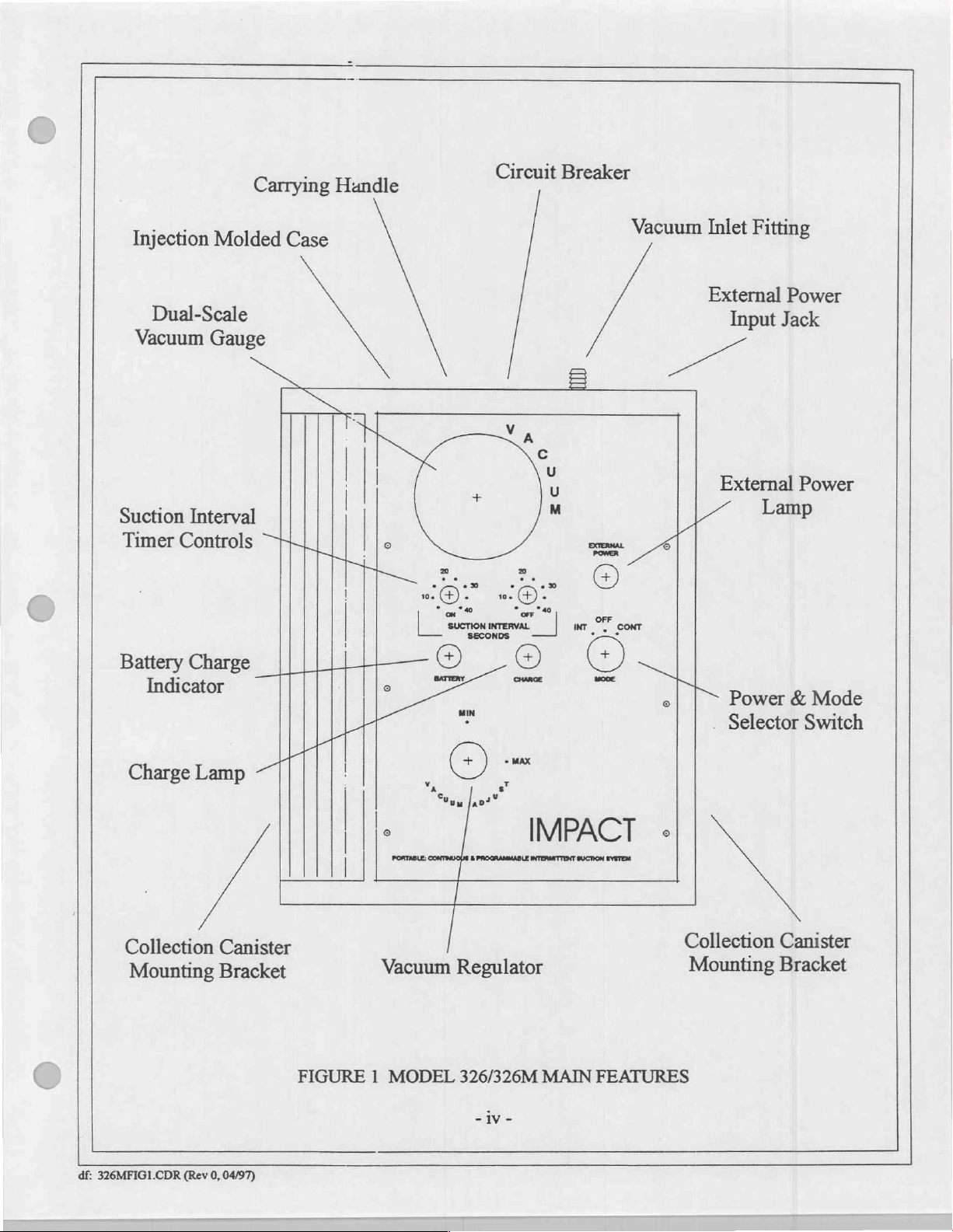
Injection
Dual-Scale
Vacuum
Suction
Timer
Interval
Controls
Carrying
Molded
Gauge
TT
Case
Handle
TS
|
|
lle
TTT
|
Circuit
Va
로
E .
0
10
Di
. > .
„©
Breaker
a
c
U
n
0
soma
Pal
©
Vacuum
a
Inlet
Fitting
External
Input
External
Lamp
Power
Jack
Power
Battery
Charge
Collection
Mounting
Charge
.
Lamp
_|||1Il_
개
<|
Canister
Bracket
一
BATTERY
i
レレ
,
FIGURE 1 MODEL
Vacuum
© ©
に
©
Regulator
326/326M
CHARGE
i
+
(+)
MODE
IMPACT
MAIN
FEATURES
rel
M
o|
PS
«
Collection
Mounting
Power € Mode
Selector
Switch
Canister
Bracket
df:
326MFIG1.CDR
(Rev
0,
04/97)
VE
Page 6
SHIPPING
Each
Model
326
.
Apparatus,
Assembly, Auto
.
Each
lea.
lea.
lea.
2ea.
lea.
lea.
2ea.
2ea.
2ea.
2ea.
lea.
2ea.
Suction
AC/DC
50/60/400
12
Model
Apparatus,
Assembly,
Suction
Fuse,
AC/DC
50/60/400
12
Hose,
Hose,
Hose,
Universal
Instruction
Case,
Strap,
Hose,
Power
VDC
326M
Hose,
Spare
Power
VDC
Clear,
Clear,
Clear,
Padded,
Velcro®
CONTENTS
is
shipped
Suction,
HZ
output)
is
Suction,
Auto
HZ
output)
PVC,
PVC,
PVC,
Canister
Manual,
with
Portable
Power
Sterile,
Supply
input;
shipped
Portable
Power
Sterile,
Supply
input;
1’
18"
2’
Attachment
Operation & Service
Aspirator
the
Cable
Clear,
6’
(115/230
nominal
with
the
Cable
Clear,
6’
(115/230
nominal
Long
Long
Long
following
Long
VAC,
following
Long
VAC,
Bracket
contents:
lea.
Hose,
lea.
Hose,
lea.
Hose,
lea.
Universal
lea.
Fuse,
lea.
Instruction
contents:
The
following
2ea.
Collection
2ea.
Filter,
lea.
Carry-all
The
following
2ea.
Disposable
lea.
Catheter,
1ea.
Catheter,
Clear,
PVC,
Clear,
PVC,
Clear,
PVC,
Canister
Spare
Manual,
are
provided
Canister
Disposable,
(for
use
with
Case
are
provided
Collection
14
French
18
French
1’
Long
18"
Long
2’
Long
Attachment
Operation
with
Assembly,
Hydrophobic/Bacterial/Overflow
reusable
with
Label
with
Canister & Lid
Bracket
NSN
6515-01-435-0050
Autoclavable
canisters
Air
only)
Force
Accessory
Kit
ACCESSORIES
The Accessories
Accessories
tity
required.
Telephone
FAX
PART
465-0005-00
540-0068-00
540-0055-00
540-0051-00
703-0326-07
703-0326-06
820-0018-00
906-0326-03
906-0326-01
906-0326-04
LIMITED
Permission
military
a
in
use
may
be
orders:
NUMBER
hereby
is
service
List
ordered
orders:
COPYRIGHT
LIST
contains
973/882-4993
granted
training
common
direct
973/882-1212
Filter,
Hose,
Hose,
Hose,
Assembly,
AC/DC
Tubing,
Instruction
Instruction
Instruction
the
to
program
items,
from
Impact.
Send
“DESCRIPTION
Disposable,
Clear,
Clear,
Clear,
Collection
Power
Suction,
Manual,
Manual,
Manual,
RELEASE
Department
other
and
required
When
PVC,
PVC,
PVC,
from
time
to
time.
Each
ordering,
written
Hydrophobic/Bacterial/Overflow
1’
Long
18"
Long
2’
Long
Jar
Supply
Sterile,
Operation & Service,
Operation,
Operation & Service,
Defense
of
technical
please
purchase
9/32"
LD. X
Model
reproduce
to
training
include
orders
to:
6”
Model
326
Model
all
programs.
item
is
the
part
Impact
P.O.
27
West
326M
326
material
furnished
preceeded
number,
Box
Fairfield
Caldwell,
by
description
Instrumentation,
508
Place
New
under
its
this
part
number.
and
quan-
Inc.
Jersey
07006
contract
for
Page 7

CALIBRATION
_
This
device
should
be
ing
specifications.
shorter
οἱ
period
DER
anual.
Calibration
between
of
UNPACKING
Check
the
of
shipping
before
contents
damage.
attempting
signs
manual
LOCATION
The
Model
326/326M
vironment,
tic
sheet,
a
etc.).
should
WARNINGS
Caution:
Federal
law
NOTICE
incorporated
preventative
300
hours
of
the
shipping
If
there
to
operate
OF
is a transportable
take
precautions
ito a regular
measurements
maintenance
of
operation.
case(s)
is
no
the
USE
REGARDING
restricts
this
device
should
inspections. A calibration
Recommended
against
apparent
instrument.
device,
and protect
therefore,
to
sale
sign
preventative
be
made
on a biannual
maintenance
the
enclosed
of
mechanical
its
physical
this
device
USE
by
or
on
the
order
maintenance program
basis
unless
check
should
checks
packing
by
list.
damage,
area
covering
of a physician.
can
Examine
read
the
of
use
will
it
with a protective
to
insure
compliance
significant
be
made
be
found
in
the
the
instrument
instructions
vary.
When
contained
operated
barrier
with
usage
warrants
following
SERVICE
for
any
within
in a wet
(small
operat-
a
each
section
obvious
this
en-
tarp, plas-
This
equipment
certified
nicians
CLEANING).
medical
Danger - Possible
Caution - Electric
only.
Do
not
operate
Disposable
Do
not
clean
is
intended
therapists.
explosion
shock
See
section
this
instrument
hydrophobic/bacterial/overflow
collection
ASSEMBLY,
ADJUSTMENTS
ASSEMBLY:
INTERCONNECTIONS:
depicts
disposable
DESCRIPTION
and
the
INITIAL
verify
No
assembly
interconnections
hydrophobic/bacterial/overflow
ADJUSTMENTS:
CONTROLS,
OF
performance
device
for
use
by
hazard
hazard,
entitled
canister
SERVICE.
prior
with
qualified
if
used
do
not
to
abrasive
remove
reading
medical
in
the
inside
the
filter
cleansers
personnel
presence
cover.
instructions
is
for
use
or
INTERCONNECTIONS
is
required
Tubing
required
Before
prior
before
placing
interconnections
connect
to
filter.
placing
CIRCUIT
to
this
interfacing
Model
the
device
BREAKER,
with
this
required
are
into
patient.
or
of
flammable
Refer
contained
only
with
(See
ROUTINE
device
into
before
326/326M
operation
CONNECTORS
person(s)
anesthetics.
servicing
reusable,
to
within
autoclavable,
CARE
AND
operation.
placing
reusable
the
to
the
read
AND
under
the
guidance
qualified
this
AND
biomedical
manual.
collection
MAINTENANCE
INITIAL
into
device
this
collection
section
entitled
INDICATORS.
i
and
instruction
equipment
canisters.
section
operation.
canisters
OPERATION,
Make
(in
control
tech-
Figure
series)
settings
of
2
and
|
Page 8
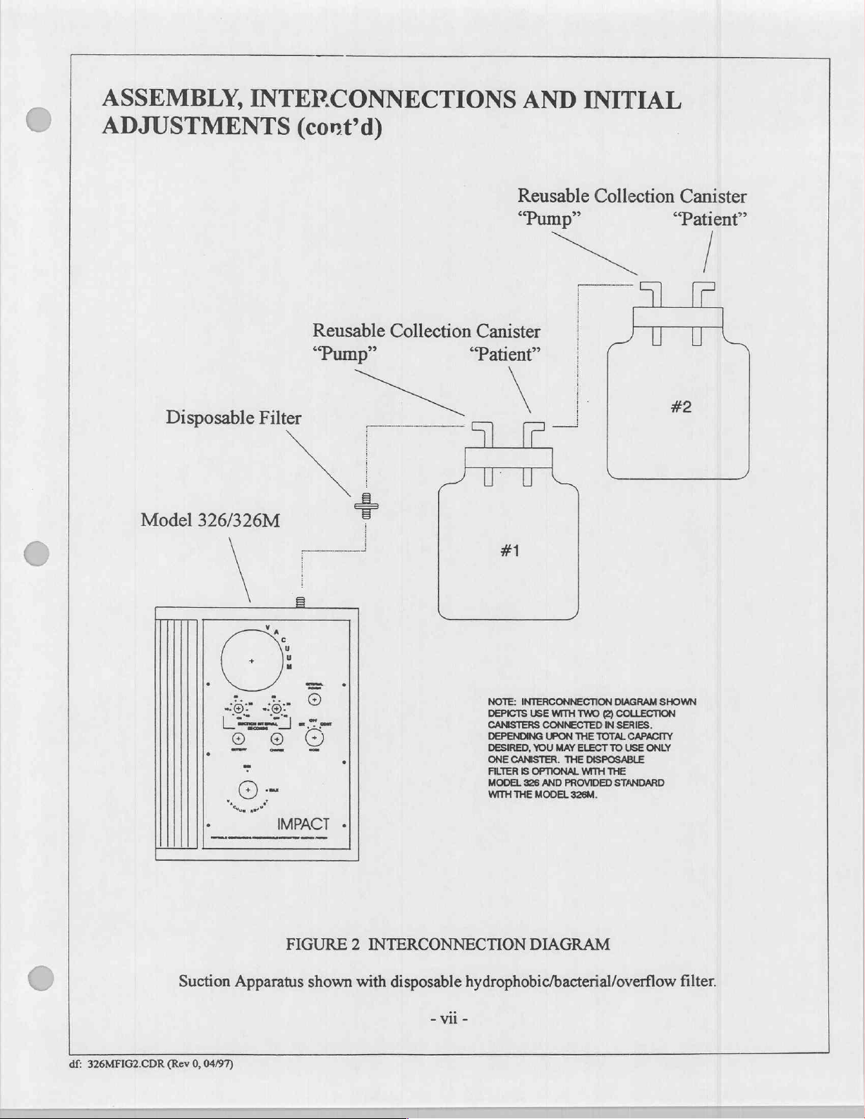
ASSEMBLY,
ADJUSTMENTS
Disposable
INTERCONNECTIONS
(cont’d)
Reusable
“Pump”
Filter
Collection
AE
ML
AND
Reusable
“Pump”
Canister
“Patient”
INITIAL
Collection
πε
(l
Canister
“Patient”
|
U
im
U
#2
Model
326/326M
IMPACT
-
#1
NOTE:
DEPICTS
CANISTERS
DEPENDING
DESIRED,
ONE
CANISTER.
FILTER
MODEL
WITH
THE
INTERCONNECTION
USE
WITH
TWO
CONNECTED
UPON
THE
YOU MAY
IS
OPTIONAL
326
MODEL
AND
ELECT
THE
PROVIDED
326M.
(2)
IN
TOTAL
TO
DISPOSABLE
WITH
THE
STANDARD
DIAGRAM
COLLECTION
SERIES.
CAPACITY
USE
ONLY
SHOWN
FIGURE
Suction
df:
326MFIG2.CDR
(Rev
0,
Apparatus
04/97)
shown
2
INTERCONNECTION
with
disposable
-
vii
DIAGRAM
hydrophobic/bacterial/overflow
-
filter.
Page 9
USAGE
APPLICATIONS - DEEP
IMPACT
Deep
drainage/gastro-intestinal
Wangensteen*),
placement
deviations
The
ON/OFF
oe
and
The
collapse
area,
tions
The
and
tract,
(18"
tinal
and
tubing
and/or
Impact
protocols.
gastro-intestinal
thus
and
intended
pushed
thus
maximum
wall,
Models
cycling
are
ea
around
preventing
hemorrhage
action
during
removing
height)
thus
relocating
MODELS
requires a thorough
lengths.
additional
306/306M
times
may
arbitrary.
tract
an
implanted
additional
at
the
of
intermitte
ON
and
accumulated
flows
it
306/306M
suction,
The
following
considerations.
and
be
varied
It is
represents a pliable
drainage
drainage
collapsed
at
OFF
cycles.
fluids.
back
into
in
time
for
DRAINAGE/GASTRO-INTESTINAL
AND
frequently
understanding
data
is
326/326M
from
recommended
site.
suction
the
the
are
patient
area
tube.
Such a collapse
while
fluids
is
to
provide a hydraulic
The
"pull"
The
"push"
drainage
next
ON
capable
to
326/326M
referred
of
"mild
for
reference
of
patient
that the
which
when
accumulate
effect
occurs
effect
occurs
site,
washing"
cycle.
PORTABLE
to
as
Wangensteen
suction"
maintaining
effectively
user
can
procedures
only
and
optimizing
select
subjected
cause
continuous
and
potential
effect
as
suction
when
fluid
the
implanted
suction
including
specific
precise
intervals
vacuum
drainage
consistent
to
continuous
ulcerations
whereby
is
applied
in
the
catheter
SUCTION
ASPIRATORS
(after
Dr.
collection
applications
suction
drainage
to
the
elevated
may
and
airflow
intervals.
with
negative
in a specific
can
lead
fluids are
gastro-intestinal
connecting
away
from
Owen
bottle
warrant
levels.
Cycling
past
practices
pressure
tissue
to
perfora-
pulled
tubing
the intes-
H.
will
It
is
important
tubing
each
has a critical
and
120
mmHg
tion,
involving
the
delivered
for
this
tal
end
of
connecting
from
actually
the
ON
creased
The
hydraulic
than
the
atmospheric
height
of
tinuous
Models
visual
objections
The
factors
considered
*"INTESTINAL
Illinois:
326USAGE.CHP
df:
particulate
suction
effect,
the
the
implanted
tubing.
entering
cycle
can
possibility
distal
end
pressure,
the
distal
suction
306/306M
involving
in
order
Chapter
to
note
that
the
height
effect on
would
raise a column
matter
strength
user
is
cautioned
suction
Since
mild
the
collection
be
extended
of
tissue
action
previously
of
the
implanted
enabling a gravitational
end
of
the
presence
to
between
and
326/326M
the
appearance
the
time
to
have
OBSTRUCTIONS"
VI.
overall
(solids),
can
only
catheter.
suction
to
compensate
occlusion
discussed
implanted
patient
and
cycles
safe,
effective
of
the
collection
performance.
of
water
approximately
blood
clots,
raise
the
drained
not
to
exceed
The
consists
canister
exists.
catheter.
catheter, a siphoning
and
collection
of
drained
(ON
and
by
an
user
should
of
minimal
prior
to
for
this,
is
only
possible
During
backflow
collection
canister
fluids
OFF),
intermittent
Owen
H.
Wangensteen,
canister
Under
4’
and viscous
contents
18"
height
between
also
airflow,
the
beginning
however,
when
OFF
cycles,
to
occur.
effect
canister
will
continue
and
seek
options
collection
suction.
vio
and
placement
normal
and
be
the
canister
conditions,
5’
respectively.
secretions
to a height
collection
discouraged
excessive
of
the
clinician
the
collection
the
Models
If
the
collecting
can
occur.
which
is
despite
regarding
height
M.D.,
"dressing”
vacuum
It
is
could
present a situation
of
roughly
from
tubing
next
OFF
must
canister
306/306M
Siphoning
undesireable.
siphoning.
and
C.C.
Thomas,
3’
bottle
using
lengths
cycle.
always
jar
is
collection
connecting
Publisher,
of
the
connecting
levels
of
possible
entry
recognize
is
and
positioned
Cycling
Clinicians
that
to
4’.
To
point
excessive
could
prevent
The
actual
at a height
326/326M
will
act
as a con-
between
canister
tubing
Springfield,
90
mmHg
mild
suc-
whereby
compensate
and
the
dis-
lengths
that
below
may
placement.
of
fluid
length
an
in-
greater
vent
to
the
the
have
must
be
of
Page 10
INTRODUCTION
The
Impact
from
the
gastrointestinal
EMI/RFI
taneous
Power
from
aircraft
designed
The
Model
power
canister
jection
handle
This
before
Model
upper
airway
and
suppression
operation
Supply
supply
device
or
electrical
to
accept
326/326M
circuits; a dual-scale
mounting
molded
and
attempting
case
mounting
is
intended
326/326M
during
abdominal
circuitry
and
battery
12
VDC
systems
DC
power
is a completely
brackets,
which
interface
to
operate
OPERATION
SECTION
is a self-contained,
oropharyngeal,
wound
recharge
using
(24
sources ranging
accessories
includes a locking
for
for
use
this
drainage;
and
is
suitable
is
the
provided
to
28
VDC)
self-contained
vacuum
and
wall,
bulkhead,
in
non-explosive
instrument.
L
multi-purpose,
nasopharyngeal
or
surgical
for
use
in
permitted
Auto
gauge
attachment
from
Power
is
permissible
from
11 to
suction
with
adjustable
battery
compartment
pole
atmospheres.
OPERATION
and
site
desert,
either
Cable
with
30
volts,
source
tubing
or
cart
suction
tracheal
debris
tropic,
115/230
accessories.
positive
vacuum
is
provided.
mounting.
Read
apparatus
suctioning
in
field
arctic
VAC,
an
appropriate
or
complete
regulator
The
door, a locking
the
instructions
designed
procedures;
hospitals.
or
aeromedical
50-400
Simultaneous
negative
with
complete
The
hz
using
cable.
The
ground.
vacuum
(limiter);
device
control
panel
contained
for
removing
programmable
apparatus
environments.
the
operation
Model
pump,
circuit
door
within
includes
provided
and/or
326/326M
controls
breaker,
is
housed
(clear),
this
secretions
Simul-
AC-DC
recharge
is
and
DC
collection
within
an
in-
carrying
manual
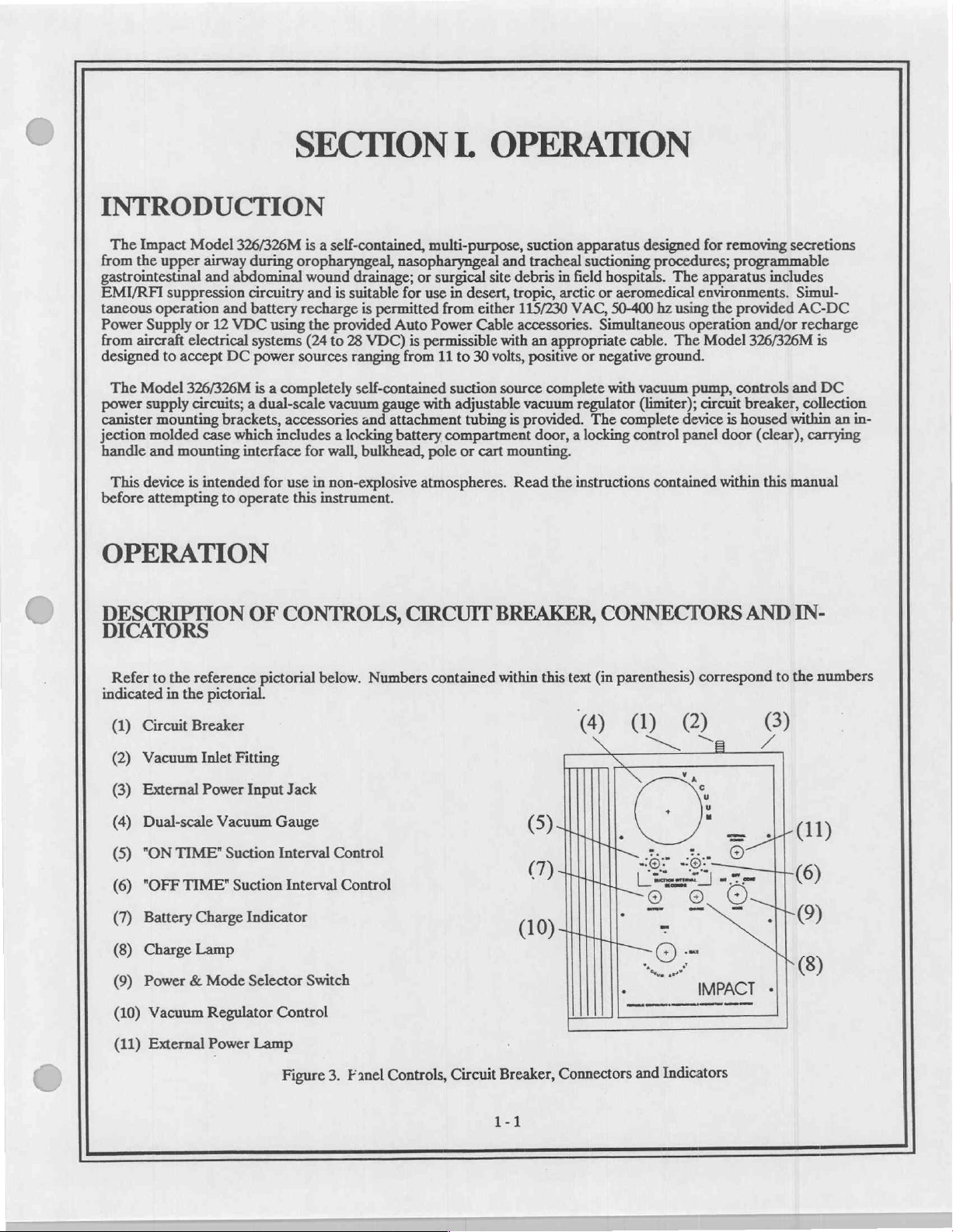
DESCRIPTION
DICATORS
Refer
to
the
reference
indicated
(1)
(2)
(3)
(4)
(5)
(6)
(7)
(8)
(9)
(10)
(11)
in
the
pictorial.
Circuit
Vacuum
External
Dual-scale
"ON
"OFF
Battery
Charge
Power
Breaker
Inlet
Power
TIME”
TIME"
Charge
Lamp
&
Vacuum
External
Vacuum
Mode
Regulator
Power
OF
CONTROLS,
pictorial
Fitting
Jack
Input
Gauge
Suction
Interval
Suction
Interval
Indicator
Selector
Control
Lamp
Switch
below.
Numbers
Control
Control
CIRCUIT
contained
BREAKER,
within
this
text
(4)
|
(5)
[ῃ
a
a
a
0)
CONNECTORS
(in
parenthesis)
(1) (2)
и
|
T
O
=
i
ei
correspond
8
с,
A
ia
cene
IMPACT
E
AND
to
(3)
Z
jin
-
IN-
the
numbers
(11)
し
(6)
(9)
®
Figure
3.
Fanel
Controls,
Circuit
Breaker,
1-1
Connectors
and
Indicators
Page 11
OPERATION
DESCRIPTION
DICATORS
(1)
Circuit
(2)
Vacuum
(3)
External
(4)
Dual-scale
(5)
"ON
(6)
"OFF
(7)
Battery
(8)
Charge
(9)
Power & Mode
Breaker - Protects
Inlet
Power
11
to
30
VDC
TIME"
TIME"
Charge
portrays
Lamp - Indicates
"INT"
suction
(cont'd)
OF
CONTROLS,
(cont'd)
Fitting - Vacuum
Input
Jack - Connection
input,
positive
Vacuum
Suction
the
Gauge - Displays
Interval
Suction
Interval
Indicator - Displays
discharged
the
Selector
mode
Switch - Turns
is
selected.
CIRCUIT
pump
motor
from
source
connection
for
or
negative
vacuum
Control - Setting
Control - Setting
battery
zone.
presence
of
operating
drawing
external
ground.
developed
determines
determines
charge
battery
charging
BREAKER,
excessive
to
filter
operating
within
status.
power
Off
current.
and
collection
and
the
how
long
how
long
Green
area
current
or
On
CONNECTORS
canister(s).
battery
patient
intermittent
from
when
recharging
circuit.
before
portrays
an
external
the
the
continuous
power.
suction
next
intermittent
the
charged
power
will
last.
zone,
source.
"CONT"
AND
Input
accomodates
cycle
the
or
intermittent
IN-
begins.
red
area
CONT - Selects
INT - Selects
(10)
Vacuum
(11)
External
OPERATING
The
Model
Mode
Selector
Regulator
Power
326/326M
Switch
SUCTIONING
all
that
Insure
1.
ly
secured,
2.
3.
vacuum
Charge
Power
Turn
pump
fittings
Lamp
should
continuous
intermittent
Time
interval
Lamp - Illuminates
POWER
is
(9)
suction
in
place
(8) will
Mode
&
begin
combinations
(Limiter)
designed
acts
as a master
tubing
as
shown
illuminate
Selector
operation.
suctioning,
suctioning,
Control - Limits
SELECTION
to
properly
is
(Figure
during
Switch
are
when
operate
power
secured
2),
operation
(9)
vacuum
vacuum
selectable
the
connected
&
from
external
switch
to
and
no
appropriate
the
to
adjustable
adjustable
maximum
STOPPING
to
respective
kinks
if
external
from 0 to
between 5 and
to a "live"
power
start
and
in
connecting
operating
position:
from 0 to
deliverable
AC
or
stop
fittings.
550
200
40
seconds
vacuum
mains.
internal
rechargeable
operation.
Verify
tubing.
power
CONTinuous
mmHg
mHg.
that
is
ON,
and 5 and
level.
batteries.
collection
applied.
INTermittent.
or
40
seconds
The
canister
lids
Power
are
internal
The
OFF.
&
proper-
to
the
(Limiter)
collection
levels
Adjust
4.
vacuum
the
Adjusted
Vacuum
tubing
and
Regulator
going
delivered
vacuum
Control
canister.
displayed
are
maximum
the
to
(10)
Deliverable
Dual-scale
the
on
1-2
vacuum
desired
levels
Vacuum
vacuum
not
will
Gauge
level
exceed
(4).
"pinching"
by
preset
the
holding
and
maximum
level.
Page 12

OPERATION,
SUCTIONING,
5. A disposable
tion
canisters.
should
be
cumulative
mediate
important
6.
is
not
7.
tion
replaced
vicinity.
that
Disposable
necessary
Reusable
of
the
VACUUM
The
Vacuum
selected
vacuum.
ing
and
by
Vacuum
the
vacuum
delivered
hydrophobic/bacterial/overflow
This
filter
hours
pump
when
of
use.
The
the
operator
collection
to
use
canisters
mechanism.
REGULATOR
Regulator
rotating
the
regulator
tubing
vacuum
(cont’d)
(cont'd)
connects
discoloration
This
filter’s
canisters,
the
disposable
should
(Limiter)
Vacuum
going
levels
between
filter
retention
be
aware
be
used
Regulator
adjustments
to
the
will
continuously
filter
the
Vacuum
of
its
is
traditionally
membrane
designed
of
aerosolized
of this
and
filter
in
conjunction
with
the
to
replace
include a built-in
disposable
(LIMITER)
(10)
works
in
conjunction
(Limiter)
should
be
patient.
Deliverable
display
is
Inlet
occurs,
retain
bacteria
aspirate
(10):
made
vacuum
during
provided
Fitting
the
and
the
filter
with
disposable
filter
to
with
clockwise
to
the
maximum
levels
operation
for
use
with
(2)
and
collection
membrane
which
would
will
create
more
accordingly.
filter
and
may
canisters.
prevent
the
inadvertent
Vacuum
to
increase
desired
will
not
on
the
Impact’s
contacts
otherwise
be
Gauge
vacuum;
exceed
dual-scale
standard
canister
aspirate,
be
resistance
used
with
overflow,
(4).
vacuum
this
Vacuum
autoclavable
(Figure
exhausted
to
airflow
your
Vacuum
counterclockwise
level
by
preset
2).
or
following
into
the
resistance.
Model
326/326M.
damage
maximum.
Gauge
or
levels
may
"pinching"
(4).
This
contamina-
to
Adjusted
collec-
filter
150
im-
It is
be
decrease
and
hold-
It
COLLECTION
Protect
promptly
Collection
accordance
commercially
the
suction
cleaned.
canisters
with
available
OPERATOR
placing
Before
operating
Verify
1.
continuous
Verify
2.
Vacuum
the
Test
3.
4,
Insure
that
CANISTER
mechanism
Use
the
disposable
may
be
repeatedly
their
respective
cleanser/disinfectants
PERFORMANCE
into
device
this
selections
power
operation,
Regulator
all
hoses
and
fittings
from
overflows
filter
in
conjunction
sterilized
instructions).
Collection
DO
please
Canister
Collection
Hose
CHECKS
operator
from
verify
¿re
the
external
intermittent
for
(10)
properly
service,
Limiter
which
may
via
autoclave,
NOT
use
note
the
Bottle:
Canister
Fittings:
perform
can
power
operation.
correct
operation
connected.
permanently
with
reusable
ethylene
abrasive
following
Polysulfone/Polycarbonate
Stainless
sources
cleansing
material
Cap:
EPDM
Steel
various
internal
or
various
at
damage
collection
dioxide
the
canisters.
gas
agents.
content:
to
checks
rechargeable
vacuum
vacuum
insure
pump
or
cold
liquid
To
determine
proper
batteries.
settings.
if
not
properly
sterilants
device
(diluted
compatibility
performance.
and
in
with
1-3
Page 13
BATTERY
The
Model
ticularly
cedures.
with
discretion
326/326M
this
much
performance
lengthy
able
to
better.
VAC
is
recharged
with
automotive
Vacuum
The
External
battery
is
required.
The
life
prevent
1.
DO
2.
DO
3.
DO
326/326M
during
The
battery
requires
so
the
and
periods
recharge
Continuous
accomplished
from
Inlet
Fitting
recharging.
of
these batteries
premature
NOT
operate
NOT
charge
NOT
store
CARE
utilizes
long
periods
pack
and
its
design
16-hours
subsequent
life
expectancy.
of
disuse
the
unit
battery
using
an
external
plug
is
furnished.
(2).
Power
Input
An
appropriate
charge
this
this
this
instrument
sealed
of
storage.
in
this
device
understood.
to
fully
recharge
Because
without
once
instrument
replenishment
every
recharging
the
AC/DC
12VDC
The
Jack
(3)
depends,
depletion
instrument
G=L
This
is
not
To
recharge
time
is
their
two
months.
from
Power
power
source
External
will
accept
cable,
to
to a great
and
reduction
where
where
with
the
cell
batteries
ensures
provide
its
usually
the
interface
the
the
batteries
an
intended
long
fully
discharged
less.
self-discharge
charging
This
will
AC
mains
Supply
extent,
accessory
too.
For external
Power
voltages
between
upon
of
battery
temperature
temperature
discharged.
which
ample
for
use
life
and
GEL
rate
is
possible.
insure
is
permissible
Input
Jack
ranging
the
life.
range
range
offer
excellent
amount
as
Cell
the
care
of
the
primary
maximum
batteries.
batteries
is
extremely
If
long-term
that
battery
supplied
between
Always
but not
12VDC
(3)
is
located
External
they
receive.
exceeds
exceeds
store
charge
power
during
power
performance
Of
course,
require
low
disuse
charge
required.
with
the
operation
on
11
and
30
Power
Following
-60‘C
to
-20'C
to
in a charged
retention
emergencies
source,
the
little
(approximately 1 1/2%
is
maintained
Model
or
the
connector
VDC
Input
60‘C
50‘C
characteristics,
and
therefore,
capabilities,
batteries
user
is
common,
Recharging
326/326M.
recharge, a connecting
for
Jack
(-76F
(-4‘F
condition.
care
at
panel
device
(3)
and
these
simple
to
to
122F).
are
to
it
80%
Batteries
operation
140‘F).
transitory
it
should
the
Model
rarely
discharged
provide
per
would
be
capacity
from
115
can
adjacent
and/or
the
power
guidelines
par-
pro-
be
used
optimum
month),
advise-
or
or
230
be
cable
to
the
source
will
4.
For
long-term
storage,
the
optimum
storage
temperature
range
is
10°C
to
30°C
(50'F
to
80“F).
Page 14
ROUTINE
CLEANING
Note:
Routine
tant.
With
shortly
thereafter
growth.
LY/REASSEMBLY).
or
326/326M
lection
stances.
In
ethylene
©
Component
The
collection
e
Exterior
Periodically
canister(s)
Disinfectant
e
Collection
decontaminations
the
device
the
event
oxide
PRIOR
canister(s)
Case
or
when
CARE
operating,
into
the
of
an
All
gas.
DISCONNECT
TO
CLEANING.
Removal
applicable,
and
filter.
spraying
Canister
simply
Vacuum
aspirate
pump
head
and
filter
DO
is
recommended
AND
which
do
spray a small
Inlet
Fitting
overflow,
components
AC/DC
should
clean
the
NOT
immerse
MAINTENANCE
not
involve
(2).
remove
POWER
be
detached
exterior
or
at
the
amount
This
should
the
pump
may
be
sterilized
SUPPLY
to
case
using a mild,
allow
liquids
regular
removal
of
disinfectant
be
head
OR
facilitate
to
intervals.
of
aspirate
performed
assembly
using a liquid
AUTO
cleaning.
non-
enter
Allow
can
directly
after
(SECTION
POWER
abrasive
the
case. A damp
to
dry.
be
effected
into
each
disinfectant, a mild
CABLE
cleanser.
using a spray
the
collection
use
to
avoid
IL.
SERVICE,
FROM
Disconnect
cloth
will
canister
risk
of
DISASSEMB-
spray
disinfectant
MODEL
Remove
suffice
in
disinfec-
and
bacterial
col-
most
in-
Impact’s
sterilants
compatibility
1.
canister,
2.
3.
4.
5.
recommended.
lier
Disposable
barb
6.
may
particulate
store
reusable
(diluted
with
Thoroughly
cap
both
Tubing
Insure
Orient
To
within
Disposable
prevent
each
at
used
be
the
device
is
considered
that
collection
this
section.
filters
end
repeatedly
matter
collection
in
accordance
commercially
clean
collection
hose
fittings
disposable
all
parts
are
canister
cross
of
risk
If
to
filters
to
are
filters
connect
facilitate
may
until
repeated
during
its
original
canisters
with a short
securely
and
contamination
not
between
quick
obtained
be
discolored
airflow
may
with
their
available
Collection
canister(s),
and
fastened
route
tubing
this
used,
the
connections
from
or
usages,
levels.
be
repeatedly
respective
cleanser/disinfectants
Canister
Collection
Hose
and
fittings
length
of
should
collection
be
and
as
the
and
should
device
to
Impact.
contact
reduction
a
properly
shown
the
sterilized
instructions).
please
Bottle:
Fittings:
tubing.
discarded
spread
canister
collection
When
with
in
Polysulfone/Polycarbonate
Canister
Stainless
after
each
This
following
connected
in
Figure 2 following
airborne
of
disinfected
be
Vacuum
and
canister
ordering,
device
and/or
airflow
aspirate
Cap:
will
via
autoclave,
Do
not use
note
EPDM
steel
use.
Handy
prevent
each
after
particulate
cleaned,
and
Inlet
and
specify
fluids
will
ethylene
abrasive
the
following
hint:
Before
accidental
use.
cleaning.
cleaning.
matter,
following
(2).
Fitting
Vacuum
Impact
occurs.
become
part
evident.
oxide
cleansing
material
emptying
spillage
use
the
each
The
Fitting
Inlet
number
filters
As
Filter
gas
or
cold
agents.
content:
collection
of
aspirate.
bacterial
of
as
use,
contains
filter
(2).
465-0005-00.
become
occluded
replacement
liquid
To
determine
filters
described
hose
a
Filters
will
is
ear-
with
re-
Page 15
ROUTINE
e
Bacterial/Overflow
Do
not
attempt
it
becomes
comes
first.
Do
not
bypass
lowed
to
accumulate
reduction
levels.
MAINTENANCE
Routine
vice.
Routine
1.
Cleaning
2.
Filter
or
following
3.
Operational
to
discolored
this
in
device
maintenance
maintenance
checks - as
checks - replace
150
hours
checks - as
CARE
clean
disposable
or
contacts
filter.
Its
in
the
airflow
will
should
described
when
of
cumulative
AND
Filter
aspirate,
intended
pump
head _ As
become
be
performed
should
consist
above.
discolored,
described
MAINTENANCE
bacterial/overflow
airflow
use
is
to
retain
filters
evident.
on
this
of
the
contact
nse.
in
OPERATOR
filters.
is
impeded,
bacteria
become
Filter
replacement
apparatus
following:
with
aspirate
PERFORMANCE
This
or
following
which
occluded
at
regular
occurs, airflow
item
is
disposable
would
with
particulate
will
restore
intervals
CHECKS.
(cont’d)
and
150
cumulative
be
expelled
device
through
matter during
performance
and
prior
performance
should
hours
of
the
to
its
being
diminishes
be
replaced
use,
whichever
exhaust
repeated
to
its
normal
placed
whenever
port
or
al-
usages,
considerably
airflow
into
ser-
a
4.
Tubing
checks - replace
crimped, cracked
or
worn
tubing
as
required.
3-2
Page 16
IN
CASE
OF
DIFFICULTY
Authorization
Impact
Such
members
ment.
OPERATOR
integrity
item
from
to
OPERATOR
contact
Instrumentation,
Impact
Common
To
If
will,
upon
departments
attend a factory
problems
of
all
or
the
suction
isolate a problem,
the
collection
the
filter,
then
the
tests
described
your
nearest
to
service
are
CORRECTIBLE
tube
vacuum
PROBLEMS
this
Inc.
request,
connections,
apparatus
canister
provide
encouraged
training
may
be
quickly
check
to
from
above
Impact
representative
instrument
assume
by
for
do
any
competent
to
contact
course. Details
rectified
tubing,
testing
the
the
not
fittings,
for
vacuum
to
the
filter
to
REQUIRING
resolve
by
other
than
factory-trained
responsibility
biomedical
the
PROBLEMS
by
vacuum
at
the
inlet of
Vacuum
the
Vacuum
an
operating
or
the
factory
may
be
users.
and
control
at
various
Inlet
Fitting;
Impact
and/or
Should
each
Inlet
SERVICE
liability
engineering
for
assistance
obtained
the
settings.
locations.
item,
tracing
or
if a filter
Fitting.
problem,
Customer
or
certified
resulting
departments
when
by
contacting
Model
326/326M
One
can
backwards
is
service
is
Service
personnel
from
such
with
needed
used:
required.
Department
and
the
Impact
fail
quickly
through
vacuum
isolate
Should
will
not
unauthorized
service
it
to
(973)
data
is
recommended
Customer
operate
from
properly,
problems
the
system,
the
servicing
882-1212.
be
given,
nor
does
servicing.
and schematics.
that
staff
Service
to
collection
be
Depart-
verify
an
accessory
i.e.:
vacuum
canister
necessary,
the
Please
quest.
have
The
the
Model
Model
and
326/326M
Serial
Numbers
Serial
Number
ready
is
located
and
any other
on
the
pertinent
outer
case
data
you
wish
identification
label.
to
include
in
your
service
re-
Page 17
STORAGE
For
prolonged
pui
of
direct
low.
When
batteries
Following
stabilize
periods
to a temperature
LIMITED
Impact
period
be
sumable
neither
authorized
Instrumentation,
of
one
warranted
in
usage,
assignable
personnel.
INFORMATION
storage
sunlight.
are
of
in
Storage
extended
WARRANTY
(1)
year.
only
for
defects
will
be
nor
transferable,
All
periods,
extended
Batteries,
warranted
the
temperatures
storage,
STORAGE
Below
68“
86°
storage
within
its
Inc.
warrants
which
of
manufacturing
warranty
Model
326/326M
should
it
is
recommended
AMBIENT
68'F (20'C)
to
86F
(20º
го
104
(30º
in
non-controlled
specified
only
no;
repairs
operating
this
instrument
by
their
for
defects
does
it
shall
range
to
30'C)
to
40'C)
nature
origin
of
apply
be
subject
should
be
stored
between
that
they
-RECHARGE
environments,
range
(see
BATTERY
to
be
free
from
are
consumable
for a period
manufacturing
if
this
of
instrument
to
return
indoors.
5‘F
and
receive a refresh
18
months
12
months
6
months
allow
all
and
ninety
origin
is
tampered
postage
The
104‘F (-15°C
INTERVAL
the
CARE).
defects
subjected
(90)
days.
prior
billing.
environment
to
40°C),
charge
Model
326/326M
in
materials
to
environmental
Disposable
to
their
initial
with,
misused
should
humidity
at
recommended
sufficient
and
workmanship
accessories,
use.
This
or
serviced
be
clean,
should
inter-
time
for
extremes,
con-
warranty
by
un-
and
be
to
a
will
is
Page 18
SPECIFICATIONS
VACUUM
FREE
TEMPERATURE
CONTROLS:
DISPLAYS:
CONNECTORS:
RANGE
AIRFLOW:
(Continuous):
(Intermittent):
OPERATING
RANGE:
0-550
mm/Hg
0-200
mmHg
30
Liters
Per
-20°C
to
Power & Mode
Vacuum
"ON
"OFF
Power
Charge
External
Battery
Vacuum
External
Regulator
TIME"
TIME"
Source
Indicator
Power
Charge
Gauge,
Vacuum
Power
Suction
(0-22
inches/mercury)
(0-8
inches/mercury)
Minute
49°C
Suction
(LPM)
(-4°F
Selector
(Limiter)
Interval
Interval
Select
Switch
Lamp
Lamp
Indicator
Dual-Scale
Inlet
Fitting
Input
Jack
to
Switch
120°F)
(Power
Control
Control
(115/230
(Meter)
(Metric/English), 2 1/2"
OFF/CONTinuous/INTermittent
(5-40
seconds,
(5-40
seconds,
VAC,
located
continuously
continuously
on
AC/DC
diameter.
Power
variable)
variable)
Supply)
PUMP
POWER:
COLLECTION
WARRANTY:
PROTECTION:
External:
Internal:
Battery
Recharge
CASE:
Material:
Size:
Weight:
115/230
12
VDC:
11-30
VDC:
Pack,
12
Time:
CAPACITY:
VAC,
VDC:
50-400
Hz:
Circuit
Continuous
Continuous
Continuous
Operating
16-hours
One
24.1
Breaker
operation
operation
operation
Time,
(maximum)
1200
ml X 2
1100
ml X 2
(1)
Polycarbonate,
cm W x
5.5
kg
year,
(12
(Model
limited,
29.2
Ibs)
and/or
recharge
and/or
2-hours
(Air
326M
as
color-through,
cm H x
recharge
and/or
recharge
(minimum,
Force)
NSN:
specified
injection-molded
12.4cm D (9.5"
with
supplied
with
supplied
(cable
when
cycled
6515-01-435-0050
W x
11.5"
not
supplied)
as
only)
Hx
AC/DC
Auto
specified)
4.87"
Power
Power
D)
Supply
Cable
Page 19
SPECIFICATIONS,
MODEL
MODEL
326
lea.
lea.
lea.
lea.
lea.
lea.
326M
lea.
lea.
lea.
2
ea.
2ea.
Hose,
(Included
Apparatus,
Suction
Hose,
Universal
AC/DC
Instruction
(Included
Apparatus,
Suction
AC/DC
Universal
Accessories):
Hose,
Clear,
Canister
Power
Manual,
Suction,
Hose,
Power
Clear,
Canister
Suction,
Sterile,
PVC,
Supply
Accessories):
Sterile,
Supply
PVC,
(cont’d)
Portable
Clear,
6’
18"
Long
Attachment
Operation
Portable
Clear,
6’
18"
Long
Attachment
Long
Bracket
Long
Bracket
lea.
lea.
lea.
lea.
lea.
lea.
2
ea.
lea.
2ea.
lea.
Assembly,
Hose,
Clear,
Hose,
Clear,
Fuse,
Spare
Padded
Assembly,
Fuse,
Hose,
Hose,
Padded
Case,
Spare
Clear,
Clear,
Case,
Auto
Power
PVC,
PVC,
Aspirator
Auto
Power
PVC,
PVC,
Aspirator
1’
2’
1’
2’
Cable,
Long
Long
Cable,
Long
Long
6°
6’
Long
Long
2
ea.
Strap,
The
The
Velcro®
following
following
are
provided
are
provided
with
2
ea.
2ea.
lea.
with
2ea.
lea.
lea.
2
ea.
NSN
6515-01-435-0050
Collection
Filter,
Carry-all
Air
Disposable
Catheter,
Catheter,
Canister
Disposable,
Case
Force
Accessory
Collection
14
French
18
French
Instruction
Assembly,
Hydrophobic/Bacterial/Overflow
with
Label
Manual,
Kit
Canister
Operation
Autoclavable
and
Lid
&
Service
SPECIFICATIONS
CONTAINED
HEREIN
REPRESENT
6-2
TYPICAL
DEVICE
PERFORMANCE
Page 20
INTRODUCTION
The
information
sonnel
trained
resulting
Impact
travel
if
prevailing
The
ter.
West
from
Instrumentation
and
meal
requested.
rates.
Impact
All
service
Caldwell,
contained
in
the
care
unauthorized
costs
resulting
The
customer
service
facility
requests
New
Jersey 07006;
may
CAUTIONARY
OPERATING
Prior
to
servicing
VOLTAGES
this
device,
SECTION
herein
and
servicing
servicing
will
provide
therefrom
will
be
encourages
be
addressed
via
NOTES
be
aware
is
intended
of
nor
service
responsible
telephone
only
this
product.
will
it
be
training
shall
be
for
dialogue
to
the
973/882-1212;
PRECAUTION
of
the
presence
for
use
The
held
liable
at
the
borne
by
costs
incurred
from
user
Service
of
IL
Manager,
SERVICE
by
factory-trained,
manufacturer
for
any
injuries
manufacturing
the
user.
Impact
by
Impact
service
potentially
personnel
Impact
or
fax
973/882-4993.
dangerous
and
certified
does
not
authorize
or
damages
site
at
no
will
perform
personnel
towards
Instrumentation,
operating
personnel
incurred
schooling charge
training
for
travel,
rectifying
Inc.,
voltages.
or
assume
therefrom.
at
the
meal,
any
service
27
Fairfield
or
military
any
obligations
to
users;
however,
customer’s
and
time - at
related
Place,
per-
site
mat-
INTERNAL
Military
Prior
unit
placing
to
until
its
contracts
battery
HELPFUL
attempting
Before
cessory
clogged.
problem
supply
related.
Check
Insure
Refer
voltages.
ALWAYS
bracelets,
and
integrity
the
collection
that
the
to
functional
a
to
safeguard
enclosed
RECHARGEABLE
may
require
operation,
into
device
this
pack
is
installed.
HINTS
repair/calibrate
to
vacuum
all
of
canisters
schematic,
segment
personal
your
liquids
keep
and
this
product
hoses
properly,
seal
assembly
the
of
well
from
away
BATTERY
to
be
that
insure
instrument,
this
tubing.
and
overflow
drawing,
when
vicinity
the
Verify
circuitry.
being
shipped
with
its
battery
its
please
Verify
shut-off
and
the
troubleshooting
live
of
pack
take
the
that
valves
pictorials
integrity
circuitry.
battery
a
pack
installed
is
moments
few
tubing
not
do
electrically
when
circuit
of
electronic
contained
and
no
has
stick,
ground
circuitry.
within a separate
that
cuts
or
presence
the
Remove
DO
the
in
filters
recharged.
insure
to
crimps
bacterial
and
troubleshooting.
and
operate
NOT
problem
it.
used)
(if
Isolate
correct
of
jewelry,
such
carton.
not
is
each
this
ac-
are
power
rings
as
not
Page 21
DISASSEMBLY/REASSEMBLY REQUIRED
Screwdriver,
Screwdriver,
Screwdriver,
10mm
socket
1/4"
socket
5/16"
socket
3/8"
socket
Pliers,
needle
Open-end
Open-end
Bench
vise
Diagonal
Cable
Tie,
3-32
Allen
Retaining Ring
Teflon
Tape
Ruler,
6"
Krytox®
TOOLS
slotted,
phillips
phillips
wrench
with
with
with
wrench,
wrench
with
Cutter
miniature
Key
Fluorinated
6"
head,
head,
drive
drive
drive
nosed
adjustable,
set,
smooth
Extractor
Grease
to
8"
small
medium
handle
handle
handle
1/4"
to
jaws
long,
#1
10"
5/8"
small
#2
DISSASSEMBLY/REASSEMBLY
BOTTOM
Verify
Door,
COVER
that
Mode
disconnect
Selector
Battery
Pack
Switch
is
connector
tip
in
and
OFF
release
position.
Disconnect
Velcro\
all
holddown
hoses
and
strap.
cables.
Remove
Open
Battery
Battery
Pack.
Compartment
Unscrew
tom
and
Top
screws
securing
bottom
Cover
ponents.
BATTERY
Front
Separator.
three
Cover.
ing
HIGHER).
crimped
of
Bottom
Connector
can
now
To
reassemble,
Perform
Cover
With
Diagonal
(3)
#6
Remove
three
(3)
Pull
bottom
To
reassemble,
by
two
(2)
6-32
Covers.
COMPARTMENT,
following
or
DO
flat
#6
Pull
Top
Bottom
Cover
Panel
be
lifted
reverse
Top
Cover.
Cutter,
NOT
washers
Battery
flat
washers
of
Top
top
reverse
Cover
cut
of
Turn
and
adjacent
secures
from
instructions
any
that
Compartment
Cover
Top
and
Phillips
Otherwise
unit
over
Top
Covers.
to
Bottom
Top
above
cut
miniature
other
secure
and
three
upwards
Cover
this
process
Front
Bind
to
Cover
process.
only
cable
above
Panel.
Head
so
that
DO
the
Condensed
Cover
Assembly.
Insure
CLEAR
if
servicing
proceed
cable
tie.
Battery
Separator,
(3)
4-40
until
Manifold
exactly.
screws
and
its
Bottom
NOT
with
to
next
tie
Using
Compartment
keps
it
is
Cover
unscrew
Operating
four
that
Battery
FRONT
Battery
step.
that
secures
1/4"
Battery
nuts
inbetween
Assembly.
Replace
washers
(4)
Compartment
socket
Compartment
that
cable
(located
is
facing
the
one
Instructions
4-40
Phillips
Pack
COVER
battery
with
drive
Separator,
secure
the
Regulator
Remove
tie.
inside
upward.
(1)
6-32
Phillips
label.
Bind
Head
connector
AND
TOP
Separator,
connector
handle,
Battery
Front Panel
Insure
Door
and
Top
that
Compartment
Switcher
Cover.
Battery
Unscrew
Bind
screws.
wires
are
COVER
Battery
wires
to
remove
and Clear
to
Top
Printed
Battery
Pack
Compartment)
five
(5)
Phillips
Head
screw
Remove
not
crimped
Compartment
Battery
three
Door
Front
Cover.
connector
between
Compartment
(3)
4-40
and
Cover.
Circuit
securing
Bind
that
is
screws.
Door,
Clear
keps
nuts
Clear
Remove
Board
wires
are not
Bot-
Head
located
Bottom
com-
and
Front
remain-
(NO
on
|
Page 22
SWITCHER
_
Unscrew
Printed
Regulator
REGULATOR
connector
Main
MAIN
Board
removing
nut.
Socket
Power
removed.
that
ribbon
Circuit
Printed
Follow
these
Unscrew
from
Printed
Follow
these
PRINTED
Unscrew
to
rear
their
Separate
Wrench.
Lamp.
To
reassemble,
each
control
cable
PRINTED
four
(4)
4-40
Board.
Circuit
instructions
PRINTED
four
(4) 1/4"
Regulator
Circuit
four
connector
Board.
instructions
CIRCUIT
(4)
of
cable
Carefully
hex,
Front
Panel.
caps
and
connectors
Carefully
reverse
is
in
its
CIRCUIT
screws
and
four
Unplug
is
2-Pin
Board.
in
hex,
Printed
in
female-to-female
loosening
remove
remove
above
full
couterclockwise
properly
connector.
reverse
CIRCUIT
male-to-female
Circuit
reverse
BOARD
Carefully
their
from
Main
nut
and
each
nut
steps.
aligned
BOARD
(4)
#4
lock
Lift
to
reassemble.
BOARD
4-40
spacers
Board.
to
reassemble.
turn
locking
Printed
washer
and
Be
and attached.
Lift
4-40
spacers
unit
over,
screws.
Circuit
with
washer
careful
not
position - this will
washers
Switcher
securing
Regulator
Make
sure
and one
with
its
Under
Board.
an
open-end
with
an
open-end
to
scratch
securing
Printed
Regulator
Printed
that
(1)
4-40
clear
door
each
collet
Remove
wrench.
Front
permit
Switcher
Circuit
header
wrench.
proper
Board
Circuit
keps
opened.
knob
Mode
Unscrew
Panel.
knob
Printed
to
Printed
Board
pins
and
nut
that
Remove
skirt
is a nut.
Selector
Main
When
pointer
Circuit
separate
Circuit
to
separate
their
secures
the
Printed
reinstalling
Board
its
Board.
its
respective
Main
two
(2)
small
Carefully
Switch
Charge
knob
Lamp
Circuit
collet
alignment.
to
header
Unplug
header
sockets
Printed
collet
remove
using
and
Board
knobs,
Make
Regulator
from
5-pin
from
align.
Circuit
knobs
each
10mm
External
can
now
insure
sure
that
by
be
CONNECTOR
Connector
Remove
two
(2)
4-40
Remove
Reverse
PUMP/MANIFOLD
The
rect
positioning
Front
Panel
PUMP/MANIFOLD/PUMP
Remove
hosebarb
Remove
pulling
and
Panel
nut
securing
keps
nuts
External
Pump/Manifold
attached
Power
above
of
as
one
IMPORTANT:
After
ID
1/8"
retaining
twisting
PANEL
is
attached
Circuit
and
two
Jack
steps
to
reassemble.
Assembly
the
Vacuum
assembly.
reassembly,
tubing
PVC
manifold.
to
from
ring
from
front
to
Breaker
(2)
#4
and
flange.
Adjust
HEAD
Note
from
Hold
Plug
side
Bottom
fiber
Remove
should
Knob
the
this
test
black
3/8"
Valve
of
panel.
Cover.
to
washers
not
orientation
hose
See
Connector
securing
tubing
be
disassembled
are
important.
to
device
barb
swivel
cuff
by
manifold
in
Bottom
Panel.
to
of
all
insure
end
at
when
using
Cover
Remove
the
External
Suction
Under
components
proper
removing,
Port.
unless
normal
operation
manifold,
of
retaining
a
disassembly
Circuit
Power
it
is
absolutely
conditions
prior
pulling
ring
for
Breaker.
Jack
to
disassembly/reassembly.
before
3/8"
and
corrugated
on
extractor.
initial
disassembly
Remove
and
flange
necessary.
treat the
returning
corrugated
ID
Pump/Manifold
section
Remove
two
to
Connector
Its
alignment
patient
for
it
hose
may
Valve
Plug
instructions.
(2)
4-40
screws,
Panel.
and
cor-
and
use.
ID
3/8
from
damage
hose.
carefully
by
Page 23

PUMP/MANIFOLD/PUMP
Using
nut
driver,
solenoid
manifold.
and a metal
mat
solenoid
and
may
This
steady.
valve plate
manifold.
pump
with
valves
The
disk
set.
With
pump
valves.
lockwashers
stick,
slightly,
Note:
The
will
insure
To
remove
Use
of
to
To
reassemble:
Make
sure
Use
teflon
Tighten
head
is
wrench
or
screws.
square-shaped
still
distance
proper
manifold
wrench(es)
head
die cut
tape
even
secure
remove
Using
under
the
soldered
Rotate
pump
securing
to
pump
between
fit
from
plate.
Follow
valve
on
1/8"
slowly
with
manifold
in
vise.
HEAD
four
(4)
the
3/32
valve
seal.
Save
to
wiring,
to
have
pump
head
body,
this
the
during
reassembly.
pump
or a vise
Separate
the
disassembly
is
seated
NPT
close
until
you
bottom.
(cont’d)
6-32
keps
allen key,
has a rubber
these parts
carefully
access
to
to
pump
is
normal
manifold
head,
use
should
plates
reach
not
to
access
instructions
properly
nipple
(no
the
0.150
CAUTION:
nuts
securing
remove
gasket.
for
reassembly
lift
pump
bottom
body.
Pull
and
the
hands
to
be
necessary.
die
before
securing
more
+/-
pump
both
sets
The
rectangular
with
off
of
6-32
of
pump
head.
pump
head
beginning
rotate
pump
Remove
cut
valve.
in
reverse.
between
than 2 1/2
.020
inches
Do
not
over
brackets.
of
screws
the
stud.
Remove
and
of
the
pump
head
two
Observe
valve plate
wraps).
between
tighten,
Lift
pump
slightly
(two
per
valve).
valve
has a metal
same
solenoid
Do
not
four
manifold
head
counterclockwise
(2)
small
the
following
Use
hands
pump
pump
and
pinch
wiring
(4)
8-32 x 3/4
from
should
phillips
notes
and
head
when
head
and
head
could
the
be
for
access
Pull
solenoids
rod, a circular
manifold;
attached
phillips
pump
0.150
while
holding
flat
head
and
plate.
rotating
manifold,
crack.
rubber
they
to
body.
Pump
+/-
.020
screws securing
cautions.
pump
head
and
bottom
Do
not
to
both
from
seal,
are
a
pump
or
head
screws
head
inches.
manifold
onto
of
tighten
Make
sure
pump
head.
After
reattaching
studs.
Align
stop
flat
on
underside
rings
with
Krytox®.
Note:
you
may
pump/manifold.
Reattach
FRONT
Unscrew
Reverse
retaining
PANEL
six (6)
above
diaphragm
solenoids,
pin
in
manifold
of
front
Carefully
have
Tighten
ring
4-40
steps
position
panel.
Check
insert
to
loosen
screws
keps
to
and
and
hoses
nuts.
reassemble.
is
top,
with
notch
plug
the
6-32 X 5/16
four
to
The
dead
center,
pump
in
in
vacuum
o-rings
on
valve,
making
(4)
6-32
complete
Front Panel
and
that
it
its
proper
plug
phillips
keps
reassembly.
adjust
valve
sure
head
nuts
can
now
setting
hole
for
it
holding
is
laying
and
on
front
damage,
is
in
completely.
screws
brackets
be
removed
properly
slide
pump
panel.
replace
Check
securing
brackets
to
from
on
pump
with
Manifold
if
necessary.
for
front
panel.
the
Top
before
brackets
and
pump
Lubricate
proper
to
pump
Cover.
reattaching
onto
four
(4)
head
should
plug
90°
rotation.
to
align
pump
6-32
valve
lay
o-
Page 24

CALIBRATION
REQUIRED
A.
Oscilloscope,
B.
Small,
C.
Stopwatch,
D.
Regulated
PROCEDURES
A.
MAXIMUM
e
1.
Set
tery
e
2.
Select
e
3.
Turn
e
4.
Occlude
EQUIPMENT
DC,
slotted
screwdriver.
minimum
DC-Power
LOW
controls
power).
INTermittent
VACUUM
VACUUM
PROCEDURE
Triggered,
0.1
second
Supply
VACUUM
for
either
AC
operation.
ADJUST
INLET
with a minimum
resolution.
(5-Ampere
LEVEL
or
DC
control
minimum
LIMIT
operation
to
fitting
and
MAXimum
5-second
rated
(insure
adjust
R20
horizontal
output)
that
batteries
(fully
clockwise).
until
Front Panel
sweep,
have
storage
been
fully
vacuum
capability
charged
gauge
desirable.
if
reads
calibrating
200
mmHg.
from
bat-
e
B.
INTERMITTENT
NOTE:
may
find
timing
reference
e
@
©
e
@
e
NOTE:
motor
input
5.
This
reading
An
oscilloscope
it
easier
1.
Set
controls
tery
power).
2.
Select
3.
Set
ON/OFF
4.
Turn
VACUUM
5.
Trigger
sweep.
seconds.
6.
Adjustments
ment.
Close
Trigger
Steps 5 and 6 above
should
may
ON/OFF
to
calibrate
points.
for
INTermittent
times
oscilloscope
verification
oscilloscope
should
be
used
be
verified
may
be
this
either
AC
operation.
for
ADJUST
sweep
to
be
to
may
and
the
using a calibrated
TIMING
used
unit
5-seconds
can
begin
within
be
CIRCUITS
to
calibrate
using a stopwatch.
or
DC
operation
ON, 5-seconds
control
to
be
monitored
oscilloscope
to
begin
made
using a storage
when
motor
+/-0.5
ON/OFF
(insure
MAXimum
when
motor
turns
seconds.
at
triggering
Again,
various
vacuum
When
off
gauge
Timing
that
OFF.
(fully
turns
and
points.
slope
Circuits
using a stopwatch,
batteries
clockwise).
on
and
type
oscilloscope.
adjust
the
use
For
set
for
applied
adjust
R12
of a storage
simplicity
the
to
as
described
have
been
R7
Adjustments
to
set
ON
circuit,
OFF
and
the
vacuum
below.
utilize
pump
fully
charged
to
set
ON
Time
type
oscilloscope
convenience,
then
reset
inlet.
However,
turn
if
calibrating
Time
circuit
should
circuit
for a 5-second
will
the
for
technicians
on
and
turn
for a 5-second
be
to
within
simplify
positive
OFF
circuit.
off
as
from
bat-
+/-
0.5
sweep.
measure-
voltage
Page 25

C.
LOW
e
1.
@
2.
e
3.
e
4.
directly
e
5.
BATTERY
Disconnect
Preset
Turn
Adjust
Disconnect
INDICATOR
and
external
external
external
between
the
remove
power
power
supply
power
the
red
external
ADJUSTMENT
battery
supply
on,
supply
and
green
power
pack
from
for
12
VDC
set
Aspirator
for
11.1-volts,
divisions.
supply,
Aspirator.
and
attach
Mode
and
adjust
reconnect
to
Aspirator
Select
R36
battery
pack.
Switch
until
the
battery
connector.
to
CONTinuous.
Low
Battery
Indicator
needle
is
centered
Page 26

CIRCUIT
EXTERNAL
circuit
which
cated
in
tion
of
either
INTERNAL
DC
Converter
and
isolated
whenever
power
jack,
power
supply
DC
TO
allow a wide
the
power
has
two
operation.
6-VOLT
and
is
only
tion.
5-VOLT
cuit.
The
provides a stable
consists
three
terminal
circuit.
AC
enables
an
external
nominal
POWER
section
6-volt
an
external
the
unit
must
DC
CONVERTER - The
external
supply
blocking
of
Both
diodes,
POWER
operational
AND
25.6-VOLT
higher
voltage
reference
C21,
C22
regulator.
power
DESCRIPTIONS
POWER
enclosure,
sections.
will
be
is
energized
SUPPLY - The
SUPPLY - Components
simultaneous
while
115
VAC
or
SUPPLIES - The
which
provides
Connector
power
plug
is
not
function
energized
input
D4
for
is
and
U8,
supplies
with
voltage
whenever a valid
and
DS,
the
INTermittent
POWER
required
for
the
and
the
The
25.6-volt
are
active
instrument
C20
230
VAC
pre-
J1
inserted
even
the
DC
to
range
that
6-volt
SUPPLIES - The
to
prevent
comparator
25.6-volt
supply
whenever
Refer
to
enclosed
operation
is
mounted
input
power.
instruments’
regulation
incorporates a switch
into
the
if a charged
plug
inserted,
DC
Converter
of
11
to
30
external
prevents
Power
reverse
Supply
mode.
the
amplifiers
circuit
supply
consists
external
schematic
P1,
F1,
VS1,
and
on
the
Connector
internal
for
externally
jack.
If
no
battery
or
the
consists
VDC,
while
DC
power
voltage
consists
Switch
SW1C
25.6-volt
from
that
controls
of
U9,
C23, C24,
of a voltage
power
diagrams.
T1,
BR1,
and
battery
recharging.
Panel
inside
power
supply
applied
that
switches
power
is
installed.
plug
must
of
FLT1,
maintaining a stable
source
from
of
C8
turns
Power
operating
the
doubling
is
present.
consists
power,
is
available
For
be
removed
U7,
is
connected.
being
thru
C11,
on
this
Supply
at
charge
D6
and
circuit
from
Rtrim,
applied
powers
indicating
D7.
C20
represent a full
All
components
the
instrument.
of
five
plus
separate
battery
at
the
plug
the
instrument
to
allow
D4,
13.5
The
to
the
and
U4.
It
section
the
when
the
power
The
5-volt
built
lamp.
around
separate
power
when
to
operate,
battery
D5
and
VDC
output.
output
converter
powers
in
the
battery
rail.
The
The
supply
the
wave
bridge
except
C20
VS1
allows
sections: a DC
6-volt,
5-volt,
to
external
it
is
inserted
the
operation.
LP2.
Its
function
This
of
this
section
during
the
timing
INTermittent
charge
monitoring
5-volt
Supply
5-volt
Power
is a simple
ICL7662
rectifier
are
lo-
selec-
to
25.6-
volt
power
into
the
external
is
section
battery
circuitry,
integrated
to
of
also
posi-
cir-
Supply
fixed
ISOLATED
battery
M1.
provides
FLT2
timing
to
mode.
C14,
the
solenoid
activates
after
operate
and
is
time
monitoring
PUMP
SOLENOID
device.
CIRCUIT - The
When
resettable
is
required
circuit
the
pump,
The
R15,
pump
S1.
at
approximately
as a monostable
C12
provide a trigger
The
off
(0-volts).
duration.
6-VOLT
set
to
is
and
CIRCUITS - There
bleed
R16,
from
D1
the
beginning
555
R16
POWER
circuit,
CONTinuous
overload
for
EMI
in
an
"ON"
when
properly
solenoid
R18,
US
stalling
When
when
is a suppression
3-seconds
is
negative
the
and
C14
SUPPLY - The
and
is
active
in
pump
circuit
consists
mode,
switch
protection,
suppression.
cycle.
calibrated,
circuit
and
D2.
flow
of
an
"OFF"
to
multivibrator,
input
pulse
edge
device
set
the
while
In
U6
is a 3-terminal
are
two
consists
When
the
is
restricted.
diode
that
cycle
conserve
which
to
the
triggered,
is
triggered,
time
isolated
the
CONTinuous
of
R17,
SW1B
D3
suppresses
the
INTermittent
will
limit
solenoids
of
S1,
O2
timing
The
suppresses
to
bring
power
during
means
so
it
will
its
output
duration
6-volt
Q4,
O5,
supplies
adjustable
the
maximum
with
respective
and
D1.
circuit
is
same
signal
reverse
the
vacuum
battery
that
it
will
trigger
goes
that
the
output
supply
consists
and
INTermittent
C16
thru
C19,
full
system
reverse
mode,
regulator.
The
in
the
that
EMF
collection
operation.
provide a single
only
high
power
EMF
R17,
04
pump
circuitry.
dump
solenoid
"ON"
cycle, the
turns
when
when
O1
(to
Vcc = 6-volts),
stays
on.
of
C33, C34,
operating
U6,
to
when
the
and
05
R20
allows
output
vacuum
Both
circuit
on
the
pump
the
solenoid
system
US
is a 555-timer
output
turns
off.
D2,
like
and
modes.
R19, R20,
the
pump.
pump’s
turn
on
adjustment
to
are
active
consists
bleed
solenoid
also
turns
to
atmospheric
pulse
Normally,
and
stays
D1,
is a suppression
U13.
SW1B,
motor
power
200mmHg.
turns
when
CB1,
Circuit
breaker
is
to
of
the
only
in
of
$2,
is
activated
on
off.
The
pressure.
circuit
that
it
is
the
output
high
for
It is
utilized
FLT2,
CB1
turned
the
Q2
off.
U6
whenever
voltage
INTermittent
Q3,
C12
to
which
dump
solenoid
It
turns
is
connected
triggered.
of
the
the
programmed
diode.
in
the
D3
and
Filter
the
applied
thru
prevent
drives
off
to
R15
timer
10-1
Page 27

TIMING
clock
how
circuit
when
set
the
allow
tion
essentially
drives
each
the
master
er
for
BATTERY
LP1.
charge
depleted,
amplifies
resistor
and
at
system supply
power
BATTERY
U12,
and
good
ground
nals
and
center
CIRCUITS - The
is a 50
long
the
that
it
is
triggered.
time
user
adjustment
T=RC.
the
buffer
other,
clock
the
timing
R21
is a 1-ohm
monitor.
and
and
for
C25
provide a stable
supply
and
Meter1.
CONTinuous
sensitivity
for
this
are
fed
R30.
U12B
the
meter
timing
Hz,
self-starting
pump
stays
is
connected
R3
period
so
U10.
into
that the
The
output
same
as
U1B,
and
that
the
to
only
circuitry,
CHARGER
resistor
The
battery
later
tapers
ground
rail.
LEVEL
references
U11A
potential, a higher supply
The
MONITORING
It
is
mode.
at
an
operating
circuit.
summing
is
an
inverting
with a battery
square
on
during
to
operate
and
C2
timer
of
the
"ON"
of
the
"ON"
the
"ON"
gates
on
"ON"
timer
trigger
is
battery
powered
R27
the
while
CIRCUIT - The
that
charger
downward
connected
reference
charging
The nominal
point
and
amplifier
amplifier
voltage
circuitry
wave
generator
an
"ON"
cycle,
as a monostable
are
driven
by
output
is
on
time.
C3,
R6,
timer
triggers
timer.
It
consists
buffer
U1A
whenever
triggers
R13
provides
the
by
R29
the
"ON"
timer
is a pulldown
battery
current
is a simple
to
about
small
voltage
as a comparator,
voltage
the
for
(25.6V)
and
monitoring
CIRCUIT - The
actual
battery voltage
away
from
divide
the
U12A
via
with a gain
of
11.1V
consists
buffer
after
battery
R28
of a master
consisting
and
multivibrator,
U1A,
it
is
and
R7
the
of
U3,
its
"OFF"
timer
when
the
resistor
charging
limiting
charger
50-75ma
that
appears
and
the
comparator.
powers
battery
voltage.
being
the
power
battery
and
of
being
present.
clock,
of
consists
triggered.
"OFF"
as
voltage
R30.
1.
of
and
provide a trigger
are
used
timer
R8
thru
R12,
output
is
whenever
"OFF"
timer
for
the
circuit
and
also
that
provides
the
battery
across
drives
Since
U10
and
circuit
is
level
Switch
monitored
rail,
the
in
R33
R34
and
two
U1C,
U1D,
U2,
R3
thru
which
means
RS
is
brought
to
adjust
the
by
means
C6,
C7
low
(off).
the
former
has
CMOS
consists
charging
active
half.
provides
timed
transistors
of
acts
as
the
higher
replenishes.
R21
as
lamp
the
signal
U11
to
prevent
whenever
monitoring
SW1A
is
12-volts.
isolated
R31
gain
R35
are
part
timers
R1,
R2,
R7,
that
input
out
delay
of
R8
and
The
"ON"
times
out.
R21
thru
current
initial
the
battery
LP1
being
an
circuit
powers
6-volt
supply
and
R32
for
of
and
interconnecting
and
C1.
The
C3,
C4,
and
C35.
it
will
provide a single
pulse
to
the 555.
on
the
instrument
multiplier
and
C36.
and
out,
U1B
Q2
R26,
sense
charging
U10
is a differential
through
measured
the
amplifiers
external
consists
this
To
allow
provide
this
stage
this
stage.
in
C5.
The
The
output
"OFF"
and
and
Q1
and
04.
U10,
resistor
current
is
charging.
R26
power
of
circuitry
the
is
used
an
in
R36
circuitry.
"ON"
timer
U2
is a 555-timer
output
C4,
R4,
front
panel
the
time
period
"OFF"
timer
of
the
"OFF"
timers
are
the
"OFF"
timer
act
as
an
output
U11A,
C25, Q6,
for
the
battery
when a battery
amplifier
R22
is
the
and
Q6.
R24,
across
R21
is
from
operating
source
is
SW1A,
circuit
to
offset
conjunction
R27
in
both
INTermittent
to
operate
supply a virtual
signal.
with
can
be
trimmed
The
controls
pulse
and
R5
to
equa-
functions
timer
slaved
to
gates
buff-
and
is
that
gain
R25
essentially
at
the
present.
thru
R36,
with
Both
sig-
R28
to
Waveforms
considerable
mance
and
leeway
over a broad
voltage
has
been
range
measurements
given
as to
of
conditions...
***NOTE***
have
been noted
what
constitutes
at
various
an
acceptable
locations
on
voltage
each
value
schematic
in
order
to
drawing.
maintain
In
most
device
cases,
perfor-
Page 28

PREVENTATIVE
Preventative
These
inspections
Preventative
If
monthly
If
monthly
VISUAL
1.
Exterior
is
intact,
2.
AC
Examine
3.
Input
NOTE:
Department
4.
Strain
respective
5.
Circuit
6.
Inspect
maintenance
maintenance
usage
usage
CHECKS:
case
that
all
Power
the
output
and
output
This
device
before
reliefs.
strain
breaker.
all
should
is
less
is
greater
Visual
housing.
assembly
Supply
tubing
Plugs.
power
line
may
replacing
Examine
relief.
This
to
MAINTENANCE
inspections
consist
than
hardware
contain
insure
of
inspections
50
hours - PMI
than
100
checks
Examine
Examine
plug
for
cords.
Inspect
shielded
any
defective
strain
reliefs
device
has a switch
that
should
both
visual
(PMI)
hours - PMI
should
include,
exterior
is
tight,
and
incoming
visible
signs
cords
line
line
at
both ends
they
are
be
incorporated
and
performance
should
be
bimonthly.
monthly.
but
of
unit
for
that
there
AC
plug
of
damage.
for
signs
cords
to
cord.
of
type
circuit
not
cracked,
INSPECTIONS
on a routine
checks,
made
as
follows:
not
be
limited
cleanliness
are
for
of
damage.
meet
each
breaker.
crimped
and
no
signs
visible
EMI/RFI
line
cord.
Verify
or
and
to:
general
of
spilled
signs
of
If
evidence
criteria.
Each
the free
dirty.
Replace
basis
to
insure
cleaning
physical
liquids
damage.
of
damage
Contact
line
cord
movement
proper
when
warranted.
condition.
or
other
Verify
that
exists,
Impact
should
defective
device
abuse.
plug
replace
Customer
be
held
of
its
"red"
tubing
performance.
Be
sure
that
blades
are
entire
Service
securely
stem.
immediately.
housing
secure.
cord.
by
its
7.
Inspect
8.
Controls
Record
Check
proper
operation.
Verify
in
device
9.
Vacuum
vacuum
10.
tion
on
dicator
replace a battery,
11.
vacuum
12.
all
fittings
and
switches.
the
settings
for
physical
alignment
specifications.
as
Battery
battery
reading.
Indcators
gauge
Labeling.
and
correct
pump/motor.
indicated
Pack
power
Check
label
and
for
Verify
and
connectors.
Examine
of
all
controls
damage,
postive
operation
Perform
Confirm
in
device
and
AC
Power
for
several
condition
it
with
displays.
cracks
and
that
all
Keplace
all
controls
and
switches
loose
mounting
stopping.
of
the
specifications.
the
Confirm
scale
labeling
During
vacuum
this
test
with
proper
Supply. Inspect
minutes
of
date
to
AC
Power
of
replacement.
the
operation
visibility.
is
intact
fittings
and
switches.
that
must
and
inappropriate
this
inspection,
adjustment
vacuum
operation
check
Make
and
of
physical
that
Supply
of
sure
legible.
port
battery
and
all
and
connectors
Check
be
returned
motion.
insure
control
and
occluded.
vacuum
the
pump/motor.
condition
is
charged
confirm
indicators,
indicator
that
their
to
their
If
the
that
that
it
of
batteries
and
that
it
meters,
rests
exhibit
positions
original
control
each
control
is
usable
Verify
and
can
hold a charge.
charges
on
the
gauges
zero
evidence
to
positions
has
over
battery
and
without
of
verify
correct
fixed-limit
and
switch
entire
suction
deliverability
connectors.
battery.
visual
vacuum
wear
or
suspected
alignment.
following
stops,
performs
range
of
maximum
Note
battery
When
it
is
displays.
applied.
the
inspection.
check
for
its
proper
indicated
Check
opera-
charge
necessary
Inspect
the
leaks.
|
in-
to
11-1
Page 29

13.
chips,
,
14.
into
aspirated
Accessories.
leaks
and
general
Mechanical
collection
into
canister
pump
Verify
that
wear.
overflow
until
if
overflow
clean
canisters,
Replace
protection.
protective
To
device
mechanism
when
verify
fails.)
suction
necessary.
is
catheters,
operation
activated.
and
of
mechanical
(Observe
tubing
overflow
when
performing
are
available.
protection,
Inspect
this
test
canisters
liquids
must
so
that
liquid
for
cracks,
be
aspirated
is
not
„Расе а bucket
canister.
15.
PERFORMANCE
1.
analyzer,
ο.
ol
2.
temporarily
100
3.
place
own
tion
collection
produce
4.
time
maximum
tion
5.
tainable
about
Turn
Disposable
Grounding
or
multimeter
cord
Leakage
microamperes.
Maximum
filter.
canister
Rate
it
canister.
Maximum
(do
not
canister
about
of
takes
vacuum
vacuum.
550
mmHg.
opened.
Filters
vacuum
of
water
unit
on
and suction
bacterial
CHECKS:
resistance.
with
and
exposed
current.
flow.
connect
using a small
to
DO
vacuum.
Record
Measure
filter
cause
fitting.
30
liters
rise
reach
300
position.
NOT
Make
If
lower
Measure
restrictions
per
(pumpdown).
mmHg
perform
With
sure
on
floor
water
and
hydrophobic
Performance
Perform
good
resolution
(unpainted
leakage
the
maximum
the
maximum
when
performing
length
of
connecting
Vacuum
minute
This
vacuums
adjust
free
when
devic=
this test
collection
that
vacuum
adjacent
this
resulting
are
to
into
collection
filters.
checks
test
with
of
and
not
current
leakage
free
this
in
valve
airflow.
With
collection
the
"patient"
should
with a filter
canister
adjust
noted,
unit.
Connect a short
canister.
Replace
should
AC
Power
fractional
anodized)
to
airflow
test).
reduced
hose.
must
reach
in
valve
check
metal
ground
current
with a flowmeter.
DO
NOT
free
Use
be
set
canister
fitting
300
or
with a collection
place,
is
set
for
air
Verify
when
discolored
include,
Supply
ohms,
with
with
connecting
to
is
occluded.
mmHg
turn
to
leaks
connected.
measure
surfaces.
the
grounding
the
unit
perform
airflow.
its
maximum
in
place
within
unit
on,
the
maximum
in
length
of
activation
or
but not
collection
be
and
Grounding
off
and
Perform
this
test
Connect
hose
having
vacuum
and
Make
4-
seconds
canister
occlude
vacuum
record
conductor
using a stopwatch,
sure
hose
to
patient
of
overflow
contacted
limited
flowmeter
"patient"
canister,
to:
Using
an
resistance
resistance
on.
Leakage
this
with a disposable
an
inside
position.
that
vacuum
when
that
has
position.
fitting
protection
with aspirate.
ohmmeter,
between
should
of
plug-connected
current
test
with
to
"patient"
diameter
This
record
adjust
connected
its
own
fitting
and
This
hoses,
and
on
collection
mechanism.
electrical
grounding
not
exceed
equipment
should
collection
canister
device
to a 1000
integral
note
unit
around
canister
having
fitting
on
properly
should
the
amount
valve
is
filter.
the
maximum
should
fittings.
safety
0.5
not
exceed
its
collec-
sized
of
set
to
ml
collec-
produce
pin
in
to
the
at-
6.
Vacuum
tween
CLEANING:
portion
1.
Clean
2.
The
3.
Replace
the
unit’s
of this
the
vacuum
gauge
accuracy.
vacuum
Refer
to
Manual.
exterior
pump/motor
filters,
hoses,
gauge
the
case
tubing,
Using a test
and
the
ROUTINE
and
reusable
requires
fittings
gauge,
test
gauge
CARE
no
AND
collection
lubrication.
and
connectors
compare
should
canister
vacuum
be
MAINTENANCE
as
readings
within
10%.
as
needed.
required.
11-2
at
various
"CLEANING*
vacuum
section
settings.
in
Readings
the
OPERATION
be-
Page 30

TROUBLESHOOTING
Continuous
Symptom:
Controls:
Check:
Symptom:
Controls:
Check:
Intermittent
Symptom:
Controls:
Suction
No
Vacuum
Mode
Selector
Vacuum
Hose
Verify
Check
Momentarily
If
If
No
Mode
Check
Remove
output
Suction
Poor
Mode
Vacuum
ON
OFF
Adjust - MAXimum,
and
hose
that
pump
interconnections
no
vacuum
voltage
is
Internal
Selector
for
charging
AC
of
BATT
Intermittent
Selector
ADJUST - MAXimum,
Time - 5
Time - 5
or
Weak
Vacuum.
Switch - CONTinuous
fully
connections
runs
select
INTermittent
is
present,
not
present,
Battery
Power.
Switch - OFF/CHARGE
current
Charger
through
Operation.
Switch - INTermittent
seconds
seconds
for
with
collection
check
verify
that
going
S1A
cracks
CB1
(allow
freely.
Rectifier.
clockwise.
or
canister(s).
Mode
and
(3A),
EXTernal
through
Select
Internal
adequate
fully
clockwise.
crimps.
verify
reset
if
POWER
R16
into
12
recharge
Verify
Jack
BATT.
power
that
at
and
is
See
time
voltage
necessary,
VDC
canister
M1.
S1B
for
not
damaged.
that
L1
illuminates.
(CONTinuous
before
testing
lid(s)
is/are
voltage
Mode)
for
sealed
tight.
presence.
and
battery
output).
test
Check:
Symptom:
Check:
Symptom:
Check:
Check
6-volt
Check
U1D,
Check
output
Check
input
Check
output
Check
overall
cables
Motor
does
Check
circuit
Perform
Check
integrity
ON
or
OFF
Perform
Check
that
signal
at
U3,
appears
output
connections
Check
Check
when
same
same
clock
pin
4.
not
Cycle
regulator
pin
11,
for
of
U1D,
to
U6
for
proper
of
U6,
and
appearance
erratic
operation
turn
on.
breaker
checks
checks
of
of
switch
does
signal
at
the
ON
of
CB1,
as
as
trigger
timer (U2,
timing
(U4)
for
proper
pin
4,
for
try
to
of
PC
reset
for
poor
SW1B.
not
end.
for
poor
appears
input
resistors
proper
clock
switching.
adjust
occurs.
output.
signal
proper
at
pin
switching.
R20
Boards
for
if
necessary.
intermittent
intermittent
U1A,
pin
of
U2,
3);
verify
R4
and
(approximately
until
motor
operates.
shorts,
bad
solder
suction
suction
3;
pin
2.
that
RS,
verify
that
when
and
above.
above.
U2,
R9
50Hz).
Adjust
connections
1
when
U1A,
pin
i _
pin
3,
goes
low, a trigger
and
R10.
R20
and/or
3,
for
200
mmHg.
loose
goes
low, a trigger
connector
]
pulse
appears
.
signal
12-1
Page 31

TECHNICAL
NOTE:
Refer
to
DOCUMENTATION
applicable
Bill
of
Material
for
Part
Number
Description
Assembly,
Top
Cover
Assembly,
Assembly,
Circuit
Main,
Switcher
Front
Printed
Boards:
Regulator,
Panel
Assembly,
FIGURE
|
Battery
4,
Pack
COMPOSITE
ILLUSTRATION
PAGE
Assembly,
DEPICTING
13 - 1
Manifold
MAJOR
x
Assembly,
SUB-ASSEMBLIES
Bottom
Cover
Page 32

ITEM
1
2
3
4
5
SEE
IMPACT
312-0018-00
325-0326-01
325-0326-02
334-0053-00
334-0054-00
BILL
OF
MATERIAL
P/N
ITEM
IMPACT
6
338-0007-00
7
346-0440-01
8
346-0632-01
9
358-0632-06
10
358-0632-08
703-0326-01
FIGURE
5,
P/N
(PAGE
13 - 21)
ASSEMBLY,
PAGE
ITEM
11
12
13
14
15
FOR
BOTTOM
13 - 2
IMPACT
362-0440-06
376-0007-00
376-0008-00
392-0750-11
404-0326-11
COMPLETE
P/N
COVER
PART
ITEM
16
AZ
NUMBER
IMPACT
416-0326-11
450-0008-00
P/N
DESCRIPTION
Page 33

ITEM
1
2
3
SEE
IMPACT
312-0041-00
338-0007-00
358-0632-06
BILL
OF
MATERIAL
P/N
ím
ITEM
703-0326-03
4
5
6
FIGURE
IMPACT
376-0007-00
376-0008-00
390-0002-00
>
P/N
(PAGE
13 - 23)
6,
ASSEMBLY,
PAGE
ITEM
次
8
9
FOR
13
Subassembly
IMPACT
392-0750-11
404-0750-91
416-0326-21
COMPLETE
TOP
COVER
-3
P/N
PART
not
shown:
ITEM
10
11
da
NUMBER
IMPACT
418-0750-31
418-0750-41
703-0326-02
P/N
DESCRIPTION
\
Page 34

04
|
(03
704-0750-03
Assembly,
Battery
Pack
ITEM
1
2
IMPACT
016-0029-00
021-0019-00
P/N
=
ITEM
3
4
IMPACT
099-0009-02
310-0016-00
P/N
/
s
ITEM
703-0326-15
5
6
IMPACT
600-0003-00
700-0326-17
P/N
Assembly,
Subassemblies
Sealants
Not
Connector
&
Shown:
Panel
0008
^
o)
06
ITEM
1
2
3
4
IMPACT
016-0062-00
081-0017-00
089-001
253-1096-41
SEE
P/N
1-00
BILLS
MATERIAL
OF
ITEM
FOR
FIGURE
5
6
了
8
COMPLETE
346-0440-01
IMPACT
335-0003-00
358-0440-08
376-0035-00
703-0326-15
&
P/N
PART
7,
ASSEMBLY,
ASSEMBLY,
(PAGE
PAGE
ITEM
NUMBER
BATTERY
IMPACT
9
404-0326-61
10
422-0326-21
11
480-0220-00
602-0001-00
12
28)and
-
13
DESCRIPTION
CONNECTOR
13 - 4
PACK
P/N
704-0750-03
ITEM
13
14
15
16
PANEL
IMPACT
700-0326-01
700-0326-24
704-0326-01
820-0037-00
(PAGE
13
-
P/N
31)
Page 35

0808
DA
go
ca
45)
se
SA
O°
06
ITEM
1
2
3
4
5
Ga
KIZA
Oo
pa
O7—
IMPACTP/N
031-0002-00
031-0010-00
041-0013-00 8 —
047-4935-00
358-0632-04
~
i
a
“08
ITEM
6
7
9
10
Items
ELWD
>
IMPACTP/N
358063205
374-0017-00
3745002600
376-0004-00
404-0326-31
ITEM
Not
IMPACT
11
404-0326-41
12
404-032651
13
602-0006-00
14
700-0326-03
15
700-0326-07
щи
|
Pump
P/N
2:8
o
Head
Disassembled
ITEM
16
17
18
IMPACT
700-0326-14
700-0326-16
703-0326-09
P/N
|
Not
shown:
VA
474813113
DA
ITEM
1
2
3
4
5
©
EN
AY
IMPACT
016-0004-00
016-0016-00
047-4935-00
092-0006-00
100-0002-00
SEE
UY
P/N
(PAGE
BILLS
|
AS
06
ITEM
OF
13 - 27)
6
7
8
9
10
MATERIAL
IMPACT
305-0001-00
348-0002-00
480-0068-00
480-0132-00
480-0210-00
703-0326-05
FOR
COMPLETE
P/N
ITEM
11
12
13
14
15
(PAGE
PART
IMPACT
480-0229-00
490-0045-01
700-0326-08
700-0326-12
700-0326-19
13 - 24);
NUMBER
P/N
and
DESCRIPTION
ITEM
16
17
18
703-0326-09
IMPACT
700-0326-20
700-0326-21
704-0326-03
P/N
FIGURE 8 ASSEMBLY,
PUMP & ASSEMBLY,
PAGE
13-5
MANIFOLD
Page 36

へ
ay
NN
o
sy
\
|
ei
il
\
\
А
©
x
NER.
EST
SA
<
|
|
=
~
~
Nr
3
Y
-
©
9)
606
VE
Hardware
(for
Board
ITEM
1
2
3
4
5
6
7
IMPACT
035-0002-00
068-0004-00
068-0005-00
092-0006-00
100-0010-00
315-0008-00
346-0440-01
Items
connecting
and
Pump
Е
(07)
(08)
(09)
P/N
SEE
FOR
Not
Shown
Printed
Assemblies):
0)
ITEM
8
9
10
11
12
13
14
BILL
FIGURE 9 ASSEMBLY,
Circuit
~
42)
43)
IMPACT
346-0632-01
358-0440-06
368-0010-00
368-0025-00
368-0028-00
376-0019-00
392-0025-00
OF
MATERIAL
COMPLETE
P/N
703-0326-02 (PAGE
PART
NUMBER
ITEM
15
16
17
18
19
20
21
FRONT
Sub-Assemblies
702-0326-01
702-0326-02
702-0326-03
IMPACT
392-0026-00
392-0029-00
392-0032-00
392-0033-00
422-0326-31
478-0002-00
480-0219-00
DESCRIPTION
P/N
13 - 22)
PANEL
Not
Shown:
703-0326-05
ITEM
IMPACT
22
540-0083-00
23
602-0001-00
24
700-0326-22
25
700-0326-23
P/N
PAGE
13 - 6
Page 37

©)
ITEM
+
NOOhWN
IMPACT
016-0004-00
016-0034-00
016-0043-00
023-0020-00
031-0009-00
047-0005-00
081-0020-00
P/N
SEE
FOR
ES
p
12121)
ITEM
10
11
12
14
8
9
13
BILL
OF
IMPACT
117-0013-00
312-0034-00
325-0326-03
334-0034-00
334-0067-00
340-0030-00
340-0048-00
MATERIAL
COMPLETE
N
P/N
ITEM
15
16
17
18
19
20
21
703-0326-06
PART
NUMBER
Not
IMPACT
346-0440-01
346-0632-01
346-0832-01
358-0440-04
358-0440-06
358-0632-10
368-0045-00
(PAGE
P/N
13 - 25)
DESCRIPTION
Shown:
ITEM
22
23
24
25
26
27
(25)
IMPACT
374-0016-00
402-0326-11
414-0326-11
606-0001-00
708-0014-00
708-0750-01
P/N
FIGURE
10
ASSEMBLY,
PAGE
AC
1
3-7
CHARGER
RECTIFIER
Page 38

(R)
ITEM
1
ITEM
IMPACT
410-0010-04
IMPACT
P/N
P/N
ITEM
2
ITEM
IMPACT
416-0016-00
IMPACT
P/N
P/N
ITEM
3
ITEM
IMPACT
540-0066-00
IMPACT
P/N
P/N
1
SEE
FIGURE
11
016-0068-00
BILLS
OF
(PAGE
13 - 32)
ASSEMBLY,
MATERIAL
FOR
COLLECTION
2
099-0004-02
703-0326-07
COMPLETE
PAGE
3
(PAGE
PART
CANISTER & AUTO
13 - 8
13 - 26);
NUMBER
and
DESCRIPTION
708-0750-01
708-0326-01
POWER
CABLE
Page 39

JO)
(©
o
É
/
/
9)
N
ASIS
ITEM
—
OAnONM
IMPACT
016-0004-00
016-0044-00
031-0002-00
092-0006-00
092-0007-00
P/N
ITEM
6
8
9
10
SEE
BILL
FOR
FIGURE
IMPACT
099-0010-02
100-0008-00
100-0009-00
374-0017-00
374-0018-00
OF
MATERIAL
COMPLETE
12
P/N
704-0326-01
PART
NUMBER
ASSEMBLY,
PAGE
13 - 9
ITEM
11
12
13
14
15
DESCRIPTION
WIRE
IMPACT
700-0326-02
700-0326-04
700-0326-05
700-0326-06
700-0326-09
(PAGE
P/N
13 - 30)
HARNESS
ITEM
16
17
18
19
IMPACT
700-0326-10
700-0326-11
700-0326-13
700-0326-18
P/N
Page 40

AS
65
Ne
ITEM
1
2
3
4
IMPACT
081-0020-00
334-0020-00
334-0030-00
402-0017-00
FIGURE
P/N
SEE
FOR
ITEM
5
6
7
540-0055-00
8
540-0068-00
BILL
OF
COMPLETE
13
ASSEMBLY,
IMPACT
410-0004-00
540-0051-00
P/N
MATERIAL
PART
ACCESSORY
PAGE
ITEM
802-0326-02 (PAGE
NUMBER
9
10
11
12
IMPACT
703-0326-06
708-0326-01
820-0004-00
820-0005-00
DESCRIPTION
KIT - AIR
13 - 10
P/N
13 - 33)
FORCE
ITEM
13
14
IMPACT
820-0018-00
906-0326-03
P/N
Page 41

ITEM
1
2
3
4
FIGURE
IMPACT
081-0020-00
334-0020-00
334-0030-00
402-0017-00
SEE
P/N
BILL
14
ITEM
OF
MATERIAL
FOR
ASSEMBLY,
IMPACT
5
465-0005-00
6
540-0051-00
7
540-0055-00
8
540-0068-00
703-0326-16
COMPLETE
ACCESSORY
P/N
PART
PAGE
(PAGE
NUMBER
13 - 11
ITEM
9
10
11
12
13 - 29)
KIT,
ARMY
IMPACT
703-0326-06
703-0326-07
703-0326-16
708-0326-01
and
DESCRIPTION
P/N
802-0326-03
(NSN
6515-01-435-0050)
ITEM
13
14
(PAGE
IMPACT
820-0018-00
906-0326-03
13 - 34)
F/N
Page 42

을
©
꼬
일
зе
>
ni
1
»
3
m
oO
出
배
07
을
lb]
pros
©
(3827
FLTI
©
O)
See
Bill
of
Material
702-0326-03,
Page
13-20,
for
complete
af:70203263.DWG
THIS
DOCUMENT
INSTRUMENTATION,
SO
UME
WITHOUT
THE
EXPRESS
INSTRUMENTATION.
STRICTLY
PROHIBITED.
AND THE
INC.
WRITTEN
INC,
IS
THE
Part
USE
Number
TOLERANCES
OTHERWISE
FRACTION
*/ー
DRAWN
|
στο
SPECIFIED
DEC
be
Rs
UNLESS
ANGLES
+-
Е
[oa
2-14-96]
Description
сео
PRINTED
SCALE
NONE
Rev.
D
IMPACT
CIRCUIT
SIZE | DRAWING
B 7 08 _ 0 3 E 6 그 0 3
SHEET 1 pr
©1995
IMPACT
BOARD
ND.
INSTRUMENTATION,
|
INC.
Page 43

2604
3AN9I4
EI-€1
9T
See
Bill
of
Material
P
©
702-0326-02,
Page
06
13-19,
for
df:70203262.DWG
NEGRO
THE
INSTRUMENTATION,
AND
DOCUMENT
INSTRUMENTATION,
STRICTLY
JE
complete
SOLE
PROPERTY
REPRODUCTION
DR
FOR
PROHIBITED,
Bras
OF
IMPACT
THE
INC.
OF
ANY
PURPOSE
Е
INC,
1S
Part
wee
USE
THIS
Number
OTHERVISE
SPECIFIED
0
[rave
DRAW?
|
СНЕС)
Ya
U
|
7
だ
09R
ge
falto
E
al
Description
SCALE
NONE
Rev.
а
PRINTED
E
M P A
SIZE | DRAWING
Β
©
1995
C Ť
CIRCUIT
]709-035έ-09
SHEET
IMPACT
INSTRUMENTATION,
1
BOARD
NO.
OF
|
INC.
Page 44

2604
38N9I4
?1-e1
LT
See
Bill
of
Material
702-0326-01,
Page
13-18,
df:70203261.DWG
“HIS
DOCUMENT
UME
SOLE
PROPERTY
INSTRUMENTATION,
AND
OR
REPRODUCTION
DOCUMENT
FOR ANY
От т EXPRESS
MIS:
INSTRUMENTATION,
STRICTLY
PROHIBITED.
for
complete
TOLERANCES
OTHERWISE
FRACTION
+=
AND
INC,
JNC,
THE
OF
PURPOSE
Ἴμρλετ
OF
15
[APPROVALS |
THE USE | DRAWN
THIS
sa
Е
Part
SPECIFIED
DEC
Ls
Number
UNLESS
ANGLES
er
DATE
2-14-96
2-14-96|
PRINT
SCALE
MENE
Rev,
Description
IMPACT
AS
>
si
SIZE | DRAWING
B
E
©1995
|
MAIN
UIT : BOARD
=
1102032601
SHEET 그 만
IMPACT
INSTRUMENTATION,
NO.
=,
그
INC,
Page 45

а
SOLENOID
in
HA
|
|
|
METER
|
BA
BLEED
SOLENOID
e
|
VACUUM
ADJUST
VACUUM | psi
GAUGE
|
PUMP?
MOTOR
VACUUM
|
|
|
一
ㆍ
一
一
-一
7
|
er
PORT
二
|
EXTERNAL
POWER
INDICATOR
s
EXTERNAL | 2?
AC
power
SUPPLY
|
|
ON/OFF
TIMERS
(INTERMITTENT
OPERATION)
|
pans
SUP
7
[
|
—
1
|
BATTERY | INDICATOR
CHARGER
D
y
E
———
j
[O
|
charme
는
INDICATOR
|
SOLENOID|
|
CONTROL
=
A
©
MOTOR
CONTROL
(INTERMITTENT
;
i
OPERATION)
—
MOTOR
CONTROL
(CONTINUOUS
OPERATION)
—
i
|
|
BATTERY
LEVEL
BATTERY | 一
PACK
===
+
SZ
一
|
FIGURE
18
PAGE
BLOCK
13-15
DIAGRAM
Page 46

ITEM
NUMBER NUMBER
0001
0002
0003
0004
0005
0006
0007
0008
0009
0010
0011
0012
0013
0014
0015
0016
0017
0018
0019
PART
701-0326-01
702-0326-01
702-0326-02
702-0326-03
703-0326-01
703-0326-02
703-0326-03
703-0326-05
703-0326-06
703-0326-07
703-0326-09
703-0326-15
703-0326-16
704-0326-01
704-0750-03
708-0326-01
802-0326-02
802-0326-03
802-0326-05
QTY
1
1
1
1
1
1
1
1
1
1
1
1
1
1
1
1
1
1
1
UMPAGT
REV
ITEM
B
Assembly,
C
Assembly, Main
E
Assembly,
В
Assembly,
A — Assembly,
C © Assembly,
A
Assembly,
А
Assembly,
B
Assembly,
O
Assembly,
A
Assembly,
0
Assembly,
0
Assembly,
0
Assembly,
0
Assembly,
A
Assembly,
B
Assembly,
B
Assembly,
0
Assembly,
NAME/
Final
Regulator
Switcher
Bottom
Front
Top
Pump
AC
Charger
Collection
Manifold
Connector
Carry
Wire
Battery
Auto
Accessory
Accessory
Accessory
MASTER
Model
DESCRIPTION
Mechanical
Printed
Circuit
Board
Printed
Circuit
Printed
Circuit
Cover
Panel
Cover
Rectifier
Canister
Panel
Case,
Hard
Harness
Pack,
4AH
or
SAH
Power
Cable
Kit,
Air
Force
Kit,
Army
Kit,
DEPMEDS
Instrumentation,
BOM
326M
Board
Board
Inc.
DESIGNATION
N/A
N/A
N/A
N/A
N/A
N/A
N/A
N/A
N/A
N/A
N/A
N/A
N/A
N/A
N/A
N/A
N/A
N/A
N/A
E
P
a
DRAWING
NUMBER
PL701-0326-01
PL702-0326-01
PL702-0326-02
PL702-0326-03
PL703-0326-01
PL703-0326-02
PL703-0326-03
PL703-0326-05
PL703-0326-06
PL703-0326-07
PL703-0326-09
PL703-0326-15
PL703-0326-16
PL704-0326-01
PL704-0750-03
PL708-0326-01
PL802-0326-02
PL802-0326-03
PL802-0326-05
800-032600
7
la
Master
Bill
Materials,
Of
Model
TITLE
326M
MODEL
WHERE
326M
USED
È
REV__
12/4/00
DATE
…
Page
13-16
Page 47

ITEM
NUMBER
0001
0002
0003
0004
0005
0006
0007
0008
0009
0010
0011
PART
|
NUMBER
016-0004-00
305-0001-00
312-0014-00
346-0440-01
358-0632-08
376-0007-00
602-0006-00
703-0326-01
703-0326-03
703-0326-15
704-0750-03
QTY
2
2
1
2
7
8
ASREQ
1
1
1
1
ITEM
NAME / DESCRIPTION
3/16"
Tubing,
Tie
Tape,
Nut,
Assembly,
Assembly,
Assembly,
Shrink,
Wrap,
Foam,
Keps,
Screw,
Phillips,
Washer,
Sealant,
Assembly,
Flat,
Vibratite
Miniature,
P/S,
White,
4-40
Pan
Head,
SS,
#6
Bottom
Cover
Top
Cover
Connector
Battery
Pack,
4"
X
I.D.
Long
2"
SS,
Panel
4AH
Long
1"
Long
6-32 X 1/2
or
SAH
DESIGNATION
à
N/A
N/A
N/A
N/A
N/A
N/A
N/A
N/A
N/A
N/A
N/A
DRAWING
NUMBER
PL703-0326-01
PL703-0326-03
PL704-0750-03
701-0326-01
|
PL
©
ーー
Assembly,
Final
TITLE
Mechanical
_
MODEL
WHERE
326M
USED
B
REV
10/4/00
DATE
=
Page
13-17
Page 48

ITEM
NUMBER
0001
0002
0003
0004
0005
0006
0007
0008
0009
0010
0011
0012
0013
0014
0015
0016
0017
“0018
0019
0020
0021
0022
0023
0024
0025
0026
0027
0028
0029
0030
0031
0032
0033
0034
0035
0036
0037
0038
0039
0040
702-0326-01
PART
NUMBER
012-0003-00
051-3643-00
054-4001-00
055-0358-00
055-0555-00
055-4310-00
055-7806-00
068-0005-00
093-0013-05
093-0029-04
093-0039-07
109-0007-00
109-0008-00
117-0018-00
200-0103-02
200-0104-02
200-0203-02
200-0223-02
200-0473-02
200-0474-02
200-0564-02
213-1002-00
213-1003-00
213-1212-00
213-3482-00
213-4701-00
214-0254-01
216-0202-00
216-0203-00
216-0204-10
240-0326-01
253-1076-21
253-2276-11
253-2276-21
253-3366-21
255-4756-11
257-1034-12
259-1044-51
346-0440-01
358-0440-04
PL
QTY
ASREQ
1
1
1
3
3
2
1
1
1
1
1
4
1
p
1
2
1
2
1
1
1
4
1
2
2
2
1
1
2
1
2
1
1
2
1
6
10
2
2
Assembly,
ITEM
NAME / DESCRIPTION
Busswire,
Transistor,
IC,
IC,
IC,
IC,
IC,
Lampholder
Header,
Header,
Header,
Socket,
Socket,
Switch,
Resistor,
Resistor,
Resistor,
Resistor,
Resistor,
Resistor,
Resistor,
Resistor,
Resistor,
Resistor,
Resistor,
Resistor,
Resistor
Resistor,
Resistor,
Resistor,
Printed
Capacitor,
Capacitor,
Capacitor,
Capacitor,
Capacitor,
Capacitor,
Capacitor,
Nut,
Screw,
Main
TITLE
18
CMOS,
DIP,
LM358N
DIP,
Timer,
ZVN4310A
TO-220,
Case
Right
Right
Straight,
IC,
IC,
Rotary,
Fixed,
Fixed,
Fixed,
Fixed,
Fixed,
Fixed,
Fixed,
Fixed,
Fixed,
Fixed,
Fixed,
Fixed,
Variable,
Vertical
Vertical
Vertical
Circuit
Keps,
Phillips,
Printed
Solid
AWG,
2N3643
CD4001AE;
MOS,
DIP,
N-Channel,
7806,
Green
w/lens,
Angle,
Angle,
Dual
14-Pin,
DIP,
8-Pin,
DIP,
3-Pole,
Carbon
Carbon
Carbon
Carbon
Carbon
Carbon
Carbon
Precision,
Precision,
Precision,
Precision,
Precision,
PM,
Mounting,
Mounting,
Mounting,
Board,
Aluminum,
Aluminum,
Aluminum,
Aluminum,
Tantalum,
10%,
Mylar,
Metallized
4-40
Head,
Pan
Board
Circuit
Quad,
LM555CN
J-FET
Voltage
+6V
Lock,
Friction
Lock,
Friction
7
Male,
Row,
Hi-Rel
Hi-Rel
3-Position,
Film,
Film,
Film,
Film,
Film,
Film,
Film,
Linear
Main
Electrolytic,
Electrolytic,
Electrolytic,
Electrolytic,
Radial,
.01
Film,
1/4W,
1/4W,
1/4W,
1/4W,
1/4W,
1/4W,
1/4W,
Metal
Metal
Metal
Metal
Metal
Taper
Trim,
Trim,
Trim,
4.7
ufd,
5%,
Zinc
Non-Shorting,
Film,
Film,
Film,
Film,
Film,
2K
20K
200K
Radial,
Radial,
Radial,
Radial,
ufd,
100V
ufd,
.1
Plated,
2-Input,
Regulator
.100
5-Pin,
.100
4-Pin,
Pins,
2
X
10K
5%,
100K
5%,
20K
5%,
22K
5%,
47K
5%,
470K
5%,
5%,
560K
1/4W,
1/4W,
1/4W,
1/4W,
1/4W,
250K
1/2W,
100
220
SU,
SU,
10V
50V
X
4-40
WHERE
NOR
Centers
Centers
Centers
.1
1%,
1%,
1%,
1%,
1%,
ufd,
ufd,
220
33
1/4
MODEL
PCB
10K
100K
12.1K
34.8K
4.7K
16V
10V
ufd,
ufd,
16V
16V
326M
USED
E
REV
DESIGNATION
N/A
Ql
Ul
U12
U,2,3,5
Q2,3,4
U4,13
LP1
BPI
BP2
BP3A
N/A
N/A
SW!
R3,8,17
R2
R6,11
RI
18
R13,
RIS
R16
R31
R28,30,33,35
R34
R4,9
29
R27,
10
R5,
R36
R32
12
R7,
N/A
C35,
36
en
C9
C4,7
CI4
6,
5,
3,
C2,
C1,8,10,26-29,32-34
N/A
N/A
10/4/00
DATE
12,
13
DRAWING
NUMBER
Page
때
13-18
Page 49

ITEM
ume
0001
0002
0003
0004
0005
0006
0007
0008
0009
0010
0011
0015
0016
0017
0012
0013
0014
0018
0019
0020
0021
0022
0023
0024
0025
0026
0027
0028
0029
0030
0031
0032
0033
0034
0035
0036
PART
une.
012-0008-00
047-4004-00
047-5825-00
051-3643-00
055-0003-00
055-0338-00
055-0340-00
055-0358-00
055-7662-00
055-9540-00
093-0036-03
093-0037-05
093-0038-07
109-0008-00
200-0102-02
200-0181-02
200-0241-02
204-0010-02
213-1003-00
213-1823-00
213-5600-00
216-0502-00
240-0326-02
252-1066-41
253-2276-11-1
255-1066-11
257-1034-12
259-1044-51
310-0024-00
310-0025-00
310-0326-00
310-0326-10
344-0003-00
346-0632-01
358-0632-06
700-0326-15
Y
1
3
2
3
1
1
3
1
2
2
7
4
4
1
1
1
1
1
1
1
1
1
1
1
1
1
1
1
1
1
1
1
1
1
1
1
ITEM
NAME
Busswire,
Diode,
Diode,
Transistor,
IC,
IC,
IC,
IC,
IC,
IC,
Header,
Header,
Header,
Socket,
Resistor,
Resistor,
Resistor,
Resistor,
Resistor,
Resistor,
Resistor,
Resistor,
Printed
Capacitor,
Capacitor,
Capacitor,
Capacitor,
Capacitor,
Insulator,
Insulator,
Heat
Heat
Lug,
Nut,
Screw,
Jumper,
18
1N4004,
Schottkey,
2N3643
AMPO2EP,
DIP,
Regulator,
TO-42,
LM340LAZ-5.0,
DIP,
LM358N
ICL7662,
DIP,
Case
221A-03,
Straight,
Right
Straight,
DIP,
IC,
Fixed,
Fixed,
Fixed,
Fixed,
Fixed,
Fixed,
Fixed,
Vertical
Circuit
Aluminum,
Aluminum,
Tantalum,
Mylar,
Metallized
Heat
Heat
6051B,
Sink
6072B,
Sink
Solder,
6-32
Keps,
Phillips,
Red,
/
DESCRIPTION
Long
1/2"
AWG,
400PIV)
(1A,
(SA,
40V)
Instrumentation
LM338K
5A,
Voltage
8V
IRF9540,
Dual
Row,
Angle,
5
Pin,
.156
Dual
Row,
Hi-Rel
8-Pin,
Film,
Carbon
Carbon
Film,
Film,
Carbon
Metal
Oxide
Precision,
Precision,
Precision,
Mounting,
Board,
Sink
Sink
#10
Pan
18AWG,
Metal
Metal
Metal
Regulator
Electrolytic,
Electrolytic,
Radial,
.01
10%,
Film,
TO-220
Pad,
TO-3
Pad,
TO-3
For
220A
For
SS,
Head,
Long.
1"
ufd,
5%,
Pkg
Pkg
Amplifier
Voltage
Male,
Female,
Trim,
Regulator
Converter
P-Channel
3
X
Centers
7
5%,
1/4W,
1/4W,
5%,
5%,
1/4W,
Film,
1W,
Film,
Film,
Film,
5K
Axial,
Radial,
16V
ufd,
10
100V
.1
ufd,
X
6-32
J-Fet
2
Pins,
X
2
1K
180
240
5%,
1/4W,
1/4W,
1/4W,
10
50V
3/8
.1
Pins,
1.0
1%,
1%,
1%,
ufd,
KA,
Centers
.1
Centers
100K
182K
560
35V
220
ufd,
10V
DESIGNATION
JP
6,7
DS,
D4,
D8
Q6
U10
U6
U8
011
U9
05
BP6A
BP4
BP3B
N/A
R23
R26
RI9
R21
R25,
37,
38
R24
R22
R20
N/A
24
C23,
C19
C17
38
C37,
C16,18,21,22,25,30,31
N/A
N/A
N/A
N/A
N/A
N/A
N/A
N/A
DRAW
at
702-0326-02
|
PL
~~
Assembly,
Regulator
TITLE
Circuit
Printed
Board
MODEL
WHERE
326
USED
E
REV
=.
Page
13-19
Page 50

ITEM
NUMBER NUMBER
0001
0002
0003
0004
0005
0006
0007
0008
PART
026-0001-00
031-0011-00
093-0034-02
093-0035-03
200-0513-02
240-0326-03
312-0058-00
602-0001-00
QTY
1
1
1
1
1
1
ASREQ
ASREQ
ITEM
NAME / DESCRIPTION DESIGNATION
VDC-out
13.8
V-in,
Module,
Filter,
Input
Header,
Right
Header,
Straight,
Resistor,
Circuit
Printed
Tape,
Copper,
Sealant,
Silicone
Switcher,
Fixed,
11-30
Module
Angle,
Friction
Dual
Carbon
Board,
EMI/RFI,
Rubber,
Lock,
Row,
Female, 3 x 2 Pin,
Film,
1/4W,
Switcher
1"
Wide,
RTV,
Translucent
.1
5%,
50'
Long
Centers,
51K
2-pin
.100
Centers
U7
FLTI
BP7
BP6B
RTRIM
N/A
N/A
N/A
DRAWING
NUMBER
702-0326-03
PL
“Assembly,
Switcher
Printed
TITLE
Circuit
Board
MODEL
WHERE
326M
USED
B
REV
10/4/00
DATE
ーー
Page
13-20
Page 51

ITEM
NUMBER
0001
0002
0003
0004
0005
0006
0007
0008
0009
0010
0011
0012
0013
0014
0015
0016
0017
PART
NUMBER
312-0018-00
325-0326-01
325-0326-02
334-0053-00
334-0054-00
338-0007-00
346-0440-01
346-0632-01
358-0632-06
358-0632-08
362-0440-06
376-0007-00
376-0008-00
392-0750-11
404-0326-11
416-0326-11
450-0008-00
QTY
1
1
1
1
1
2
4
2
2
2
4
2
2
2
2
1
8
ITEM
NAME / DESCRIPTION
Tape,
Foam,
White,
Label,
P/S,
Mylar,
Label,
I.D.
Strap,
Velcro,
9"
Strap,
Velcro,
10"
Rivet,
Blind,
1/8"
Nut,
Keps,
4-40
Nut,
Keps,
6-32
Screw,
Phillips,
Screw,
Phillips,
Screw,
Truss
Head,
Washer,
Washer,
Knob,
Bracket,
Cover,
Bumper,
Flat,
SS,
Flat,
SS,
Molded,
Slide,
Bottom,
Rubber,
P/S,
Condensed
Long,
Long,
Dia,
Pan
Head,
Pan
Head,
Phillips, SS,
#6
#4
Door
Molded,
EMI/RFI,
Foot,
4"
Long
Operating
w/D-Ring
w/
Hook
Aluminum,
SS,
6-32 X 3/8
SS,
6-32 X 1/2
3.20"
(Nickel
P/S,
Round,
Instructions & Warning
Dome
Head,
4-40 X 3/8
Coated)
1/2"
Dia. X 1/8",
19/32"
Long N/A
Blk
DESIGNATION
N/A
N/A
N/A
N/A
N/A
N/A
N/A
N/A
N/A
N/A
N/A
N/A
N/A
N/A
N/A
N/A
DRAWING
NUMBER
|
703-0326-01
PL
=
Assembly, Bottom
TITLE
Cover
MODEL
WHERE
326M
USED
A
REV
10/4/00
DATE
E
Page
13-21
Page 52

Απο
ITEM
0001
0002
0003
0004
0005
0006
0007
0008
0009
0010
0011
0012
0013
0014
0015
0016
0017
0018
0019
0020
0021
0022
0023
0024
0025
0026
0027
0028
0029
PART
κ
035-0002-00
068-0004-00
068-0005-00
092-0006-00
100-0010-00
315-0008-00
346-0440-01
346-0632-01
358-0440-06
368-0010-00
368-0025-00
368-0028-00
376-0019-00
392-0025-00
392-0026-00
392-0029-00
392-0032-00
392-0033-00
.
422-0326-31
`
478-0002-00
480-0219-00
540-0083-00
602-0001-00
700-0326-22
700-0326-23
702-0326-01
702-0326-02
702-0326-03
703-0326-05
А
1
2
1
4
1
1
1
4
4
4
5
4
4
2
2
2
1
1
1
1
1
1
ASREQ
1
1
1
1
1
1
ITEM
NAME
Meter,
Low
Bulb,
Incandescent,
Lampholder
Crimp
Terminal,
Connector,
Gauge,
Vacuum,
Nut,
Keps,
4-40
Nut,
Keps,
6-32
Screw,
Phillips,
Spacer,
Hex,
Spacer,
Hex,
Spacer,
Hex,
Washer,
Knob,
Knob,
Knob,
Knob,
Knob,
Panel,
Orifice
Cap,
Hose,
Sealant,
Jumper,
Jumper,
Assembly,
Assembly,
Assembly,
Assembly,
Lock,
Collet,
Cap,
Nut Cover,
Collet,
Cap,
Front,
Restrictor,
Brass,
8"
Long
Silicone
Red,
Green,
Main
Regulator
Switcher
Pump
/
DESCRIPTION
Battery
Indicator
14V,
80mA
w/lens,
Green
.1
Spacing
4-Pin,
.100
Centers
2"
O.D.
CBM,
Pan
Head,
SS,
4-40 X 3/8
Threaded,
Threaded,
Threaded,
Internal
Gray
Black w/Indicator,
Black
Gray
Square
1/4"
22AWG,
Female,
Male-to-Female,
Male
Tooth,
w/Indicator,
Black
Matte
w/Indicator,
Hole
.010"
Orifice,
NPTF
Rubber,
22
Printed
5"
AWG,
Circuit
Printed
Printed
RTV,
Long
5"
to
SS,
1/8"
w/Indicator,
1/4"
Long N/A
Circuit
Circuit
Dual
Scale,
4-40 X 5/8"
4-40 X 3/4"
Female,
4-40 X 1/2
#4
1/8"
Shaft
Shaft
21mm
Shaft
10/32
THD X 1/8
Translucent
Board
Board
Board
1/4"
NPTM
Long,
1/4"
Brass/Zinc
Long,
Brass/Nickel
Long,
Alum.
Shaft
ID
Hose
Barbs
DESIGNATION
N/A
N/A
N/A
NA
N/A
N/A
N/A
N/A
N/A
N/A
N/A
N/A
N/A
N/A
N/A
N/A
N/A
N/A
N/A
N/A
N/A
N/A
N/A
NA
N/A
N/A
N/A
N/A
DRAW
NUMBER
703-0326-02
PL
Assembly,
Front
TITLE
Panel
MODEL
WHERE
326M
USED
€
REV
10/4/00
-
DATE
—Page
13-22
Page 53

ITEM
NUMBER
0001
0002
0003
0004
0005
0006
0007
0008
0009
0010
0011
0012
PART
NUMBER
312-0041-00
338-0007-00
358-0632-06
376-0007-00
376-0008-00
390-0002-00
392-0750-11
404-0750-91
416-0326-21
418-0750-31
418-0750-41
703-0326-02
QTY
2
1
2
2
1
1
1
1
1
1
1
1
ITEM
NAME / DESCRIPTION
Tape,
Foam,
White,
P/S, 1 1/2"
Rivet,
Blind,
1/8"
Dia,
Aluminum,
Screw,
Phillips,
Washer,
Washer,
Handle
(With
Knob,
Molded, Door N/A
Bracket,
Cover,
Top,
Door,
Battery
Door,
Top
Assembly,
SS,
Flat,
SS,
Flat,
Mounting
Battery
EMI/RFI,
Compartment
Cover
Front
Pan
Head,
#6
#4
Compartment
(Nickel
Panel
Lg
SS,
6-32
Flanges)
Divider
Coated)
Divider,
Dome
X 3/8
EMI/RFI
(Nickel
Head,
Coated)
19/32"
Long N/A
(Nickel
Coated)
DESIGNATION
N/A
N/A
N/A
N/A
N/A
N/A
N/A
N/A
N/A
N/A
DRAWING
NUMBER
|
703-0326-03
PL
Assembly,
Top
TITLE
Cover
MODEL
WHERE
326M
USED
A
REV
10/4/00
DATE
ší“
Page
13-23
Page 54

ITEM
NUMBER
0001
0002
0003
0004
0005
0006
0007
0008
0009
0010
0011
0012
0013
0014
0015
0016
0017
0018
PART
NUMBER
031-0002-00
031-0010-00
041-0013-00
047-4935-00
358-0632-04
358-0632-05
374-0017-00
374-0026-00
376-0004-00
404-0326-31
404-0326-41
404-0326-51
602-0006-00
700-0326-03
700-0326-07
700-0326-14
700-0326-16
703-0326-09
QTY
1
1
1
1
2
4
2
1
6
1
1
1
ASREQ
1
1
1
1
1
ITEM
NAME / DESCRIPTION DESIGNATION
Ferrite
Filter,
Low
Pass,
EMI
Pump,
Vacuum,
Diode,
1N4935,
Screw,
Phillips,
Screw,
Phillips,
Terminal,
Terminal,
Washer,
Bracket,
Bracket,
Bracket,
Sealant,
Jumper,
Jumper,
Jumper,
Jumper,
Assembly,
Diaphragm,
Fast
Pan
Pan
Insulated,
Insulated,
Lock,
Internal
Left
Right
Filter
Mounting
Vibratite
Black,
18AWG,
Black,
18AWG,
Red,
18AWG,
Red,
18AWG, 1 1/2"
Manifold
Recovery
Head,
SS,
Head,
SS,
Ring,
#6
Ring,
1/4"
Tooth,
4"
8"
11"
Long.
In-Line
6-32 X 1/4
6-32 X 5/16
Stud,
16-14
Stud,
SS,
#6
Long.
Long.
Long.
Ports,
AWG,
16-14
12V
AWG,
Blue
Blue
N/A
N/A
N/A
N/A
N/A
N/A
N/A
N/A
N/A
N/A
N/A
N/A
N/A
N/A
N/A
N/A
N/A
N/A
DRAWING
NUMBER
703-0326-05
PL
©
Assembly,
Pump
TITLE
MODEL
WHERE
326M
USED
A
REV
10/4/00
DATE
Page
13-24
Page 55

MER
ITEM
0001
0002
0003
0004
0005
0006
0007
0008
0009
0010
0011
0012
0013
0014
0015
0016
0017
0018
0019
0020
0021
0022
0023
0024
0025
0026
0027
PART
ui
016-0004-00
016-0034-00
016-0043-00
023-0020-00
031-0009-00
047-0005-00
081-0020-00
117-0013-00
312-0034-00
325-0326-03
334-0034-00
334-0067-00
340-0030-00
340-0048-00
346-0440-01
346-0632-01
346-0832-01
358-0440-04
358-0440-06
358-0632-10
368-0045-00
374-0016-00
402-0326-11
414-0326-11
606-0001-00
708-0014-00
708-0750-01
QTY
5
2
1
1
1
1
1
1
1
1
1
1
1
1
4
1
2
4
4
1
1
2
1
1
ASREQ
1
1
NAME
ITEM
Tubing,
Tubing,Shrink,
Tubing,
Shrink,
Shrink,
Transformer,
Attenuator,
Diode,
Fuse,
Switch,
Tape,
Label,
Fuseholder,
Collar,
Bushing,
Bushing,
Nut,
Nut,
Nut,
Screw,
Screw,
Screw,
Spacer,
Terminal,
Case,
Chassis,
Silicone
Line
Assembly,
Split
Bridge
Midget,
Rotary,
Foam,
Serial
Universal,
Strain
Strain
Strain
4-40
Keps,
6-32
Keps,
8-32
Keps,
Phillips,
Phillips,
Phillips,
Nylon,
Insulated,
Charger
AC
Charger/Rectifier
Grease
SJT,
Cord,
Cable,
Power,
White,
Number,
Relief,
DESCRIPTION
/
1"
X
I.D.
3/16"
1"
X
I.D.
1/8"
4"
X
I.D.
3/16
115/230VAC
Channel,
Rectifier,
2A,
Voltage
Relief,
Relief,
Pan
Pan
Pan
.625"
Or
18
Assembly
12A,
250V
Select
Lg
3"
Heat
&
In-line,
Cable
Nylon,
Nylon,
Head,
Head,
Head,
X
O.D.
#10
Ring,
Rectifier
Sink
Heat
3
AWG,
Shielded,
SOPIV
Mounting
Zinc
SS,
SS,
342
Compound
Cord,
2-Con-w/molded
Long
Long
Long
Sink,
Red
w/Nut,
Lg.
W/Nut,
Lg.
Plated,
4-40
6-32
1.D.
Stud,
Primary
326/326M
Leads
4-40
3/8
X
5/8
X
.375"
X
16-14
Long
120"
14VAC,
to
LTF
LFT9,
X
AWG,
2.5
Power
11,
Black
1/4
Long
Blue
MM
3A
Supply
Black
Plug,
Secondary
Sft
DESIGNATION
N/A
N/A
N/A
N/A
N/A
N/A
N/A
N/A
N/A
N/A
N/A
N/A
N/A
N/A
N/A
N/A
N/A
N/A
N/A
N/A
NA
N/A
NA
N/A
N/A
N/A
N/A
ας.
703-0326-06
Assembly,
AC
TITLE
Charger
Rectifier
MODEL
WHERE
—
326M
USED
B
REV
10/4/00
DATE
Page
13-25
||
Page 56

ITEM
NUMBER
0001
0002
0003
PART
NUMBER
410-0010-04
416-0016-00
540-0066-00
TY
을
2
1
1
TEM
|
Collection,
Jar,
Cap,
Molded,
Elbow,
Tube,
DESCRIPTION
/
NAME
Polysulfone/Polycarbonate,
83mm
LD.
.319"
SS,
.375"
X
O.D.
RESIGNATGH
N/A
N/A
N/A
DRAWING
NUMBER
703-0326-07
PL
Assembly,
Collection
TITLE
Canister
MODEL
WHERE
326M
USED
O0
REV
10/4/00
DATE
Page
13-26
Page 57

ITEM
NUMBER
0001
0002
0003
0004
0005
0006
0007
0008
0009
0010
0011
0012
0013
0014
0015
0016
0017
0018
PART
NUMBER
016-0004-00
016-0016-00
047-4935-00
092-0006-00
100-0002-00
305-0001-00
348-0002-00
480-0068-00
480-0132-00
480-0210-00
480-0229-00
490-0045-01
700-0326-08
700-0326-12
700-0326-19
700-0326-20
700-0326-21
704-0326-03
QTY
2
1
2
5
1
3
1
1
1
1
1
1
1
1
1
1
1
1
NAME
ITEM
Tubing,
Tubing,
Tie
Nipple,
Shrink,
Shrink,
1N4935,
Diode,
Terminal,
Crimp
Connector,
Wrap,
Stop,
Pin,
Barb,
Hose
Close,
45
Elbow,
Swivel,
Elbow,
Plug
Valve,
Jumper,
Jumper,
Jumper,
Jumper,
Jumper,
Assembly,
Black,
Red,
Orange,
Orange,
Grey,
DESCRIPTION
/
I.D.
3/16"
LD.
3/8"
Recovery
Fast
Spacing
.1
5-Pin
Long
Chrome,
Street,
10-32
WG,
22A
22AWG,
22AWG,
22AWG,
22AWG,
4"
1/8"
1/8"
1/8"NPTM
x
9"
11"
Miniature,
Knob
Chrome,
Deg.,
Manifold/Valve
X
1
X
NPTM
NPTM
1/8"
Long.
9"
Long.
9"
11"
Long.
Long
1"
Long
1/2"
to
Tube,
Long.
Long.
I.D.
3/8"
1/8"
X
1/8"NPTF
x
Black
Tube
NPTM
,
.500
Long
DESIGNATION
N/A
N/A
N/A
N/A
N/A
N/A
N/A
N/A
N/A
N/A
N/A
N/A
N/A
N/A
N/A
N/A
N/A
N/A
DRAWING
NUMBER
703-0326-09
PL
Assembly,
Manifold
TITLE
MODEL
WHERE
326M
USED
A
REV
10/4/00
DATE
Page
Lİ
13-27
Page 58

ITEM
NUMBER
0001
0002
0003
0004
0005
0006
0007
0008
0009
0010
0011
0012
0013
0014
0015
0016
PART
|
NUMBER
016-0062-00
081-0017-00
089-001
253-1096-41
335-0003-00
346-0440-01
358-0440-08
376-0035-00
404-0326-61
422-0326-21
480-0220-00
602-0001-00
700-0326-01
700-0326-24
704-0326-01
820-0037-00
1-00
QTY
1
1
1
1
1
6
6
2
2
1
1
ASREQ
1
1
1
1
ITEM
NAME / DESCRIPTION
Tubing
Cable
Wrap,
Blk,
Circuit
Breaker,
Connector,
Capacitor,
Flange,
Panel
Keps,
Nut,
Screw,
Phillips,
Washer,
Bracket,
Panel,
Hose
Sealant,
Jumper,
Jumper,
Assembly,
Hose,
Flat,
Connector
Barb,
Silicone
Black,
Red,
Spiral,
5A,
PMF,
Aluminum,
Mounting
4-40
Pan
Fiber,
Jack,
Power-Type
Union
Rubber,
18AWG, 2 1/2"
18
AWG,
Harness
Wire
8"
Long
32VDC,
2.5mm
Electrolytic,
Head,
#4
Bulkhead,
1/2" X 5"
PIN,
SS,
PM,
RTV,
3"
Long
250VAC
Moulded
4-40 X 1/2
Long.
PC
Radial,
3/8" X 3/8
Translucent
Mount
10,000
DESIGNATION
w/Switch
ufd,
35V N/A
N/A
N/A
N/A
N/A
N/A
N/A
N/A
N/A
N/A
N/A
N/A
N/A
N/A
N/A
N/A
DRAWING
NUMBER
B404-0326-61
B422-0326-21
703-0326-15
PL
>
‘Assembly,
Connector
TITLE
Panel
MODEL
WHERE
326M
USED
0
REV
10/4/00
DATE
=
Page
13-28
Page 59

ITEM
NUMBER
0001
0002
0003
0004
0005
PART
NUMBER
313-0009-00
313-0010-00
313-0013-00
325-0300-07
402-0005-00
QTY
1
1
1
1
1
ITEM
NAME / DESCRIPTION
Foam,
Die
Cut,
Pad,
Lid,
Base,
Pad,
Cut,
Die
Foam,
Foam,
Die
Cut,
Pad,
Insert
P/S,
Label,
Case,
HDPE,
Anodized
Mylar,
Black,
23" X 16" X 7"
19
3/8" x 12
1/4"
18
Name
3/8" x 1"
1/4"
14
x
Model
&
x
I
DESIGN
84108
N/A
N/A
N/A
N/A
N/A
DRAWING
NUMBER
703-0326-16
PL
Assembly,
Carry
ITLE
Case,
Hard
MODEL
WHERE
326M
USED
0
REV
10/4/00
DATE
Page
13-29
Page 60

ITEM
NUMBER
0001
0002
0003
0004
0005
0006
0007
0008
0009
0010
0011
0012
0013
0014
0015
0016
0017
0018
0019
PART
NUMBER
016-0004-00
016-0044-00
031-0002-00
092-0006-00
092-0007-00
099-0010-02
100-0008-00
100-0009-00
374-0017-00
374-0018-00
700-0326-02
700-0326-04
700-0326-05
700-0326-06
700-0326-09
700-0326-10
700-0326-11
700-0326-13
700-0326-18
QTY
2
1
4
2
5
1
1
1
1
2
1
1
1
1
1
1
1
1
1
ITEM
NAME /
Tubing,
Shrink,
Tubing,
Shrink
Ferrite
Terminal,
Crimp
Crimp
Terminal,
Plug,
Black
Connector,
Connector,
Terminal,
Terminal,
Jumper,
Jumper,
Jumper,
Jumper,
Jumper,
Jumper,
Jumper,
Jumper,
Jumper,
Black,
Black,
Black,
Black,
Black,
Red,
Red,
Red,
Orange,
DESCRIPTION
3/16"
3/4
I.D. X 3"
Spacing
.1
.156
Wire
Insulated,
.156
5-Pin,
2-Pin,
.100
Insulated,
Insulated,
18AWG,
18AWG,
18
AWG,
18AWG,
22AWG,
18AWG,
22AWG,
22AWG,
22AWG,
I.D. X 1"
Spacing
Centers
Centers
Ring,
#6
Ring,
#4
3"
6"
7"
9"
11"
9"
Long.
Long.
7"
11"
7"
Long
Stud,
Stud,
Long.
Long.
Long
Long.
Long.
Long.
Long.
Long
16-14
22-18
AWG,
AWG,
Blue
Red
DESIGNATION
N/A
N/A
N/A
N/A
N/A
N/A
N/A
NA
N/A
N/A
N/A
N/A
N/A
N/A
NA
N/A
N/A
N/A
NA
DRAWING
NUMBER
704-0326-01
Assembly,
TITLE
Wire
Harness
MODEL
WHERE
326M
USED
0
REV
10/4/00
DATE
Page
13-30
Page 61

ITEM
NUMBER
0001
0002
0003
0004
0005
0006
PART
|
NUMBER
016-0029-00
021-0019-00
099-0009-02
310-0016-00
600-0003-00
700-0326-17
QTY
1
2
1
1
ASREQ
1
ITEM
NAME / DESCRIPTION
123mm
Tubing,
Shrink,
Battery,
Gel-Cel,
Plug,
Red
Insulator,
Glue,
Jumper,
Battery
Stick
Orange,
Wire
6VDC,
Insulated,
18AWG,
X
Flat
5.0AH,
3"
Long.
3/4"
9
6VDC,
Long
5.6AH
DESIGNATION
N/A
N/A
N/A
N/A
N/A
N/A
DRAWING
NUMBER
704-0750-03
PL
Assembly,
Battery
_
TITLE
Pack,
4AH
or
=
5AH
0
MODEL
WHERE
326M
USED
0
REV
10/4/00
DATE
Page
13-31
Page 62

ITEM
NUMBER
0001
0002
0003
PART
NUMBER
016-0068-00
099-0004-02
708-0750-01
QTY
1
1
1
ITEM
NAME / DESCRIPTION
Tubing,
Shrink,
CMM,
Plug,
Assembly,
2-Cond,
Cable,
3/8"
LD. X 5/8"
Auto
Shielded,
Long,
Type
2-Con-w/molded
2.5
MM
Plug,
Sft
DESIGNATION
N/A
N/A
N/A
DRAWING
NUMBER
708-0326-01
PL
“Assembly,
Auto
TITLE
Power
Cable
Е
-
WHEREUSED_
MODEL
326M
|
A
REV
10/4/00
—
DATE
=
Page
13-32
Page 63

ITEM
NUMBER
0001
0002
0003
0004
0005
0006
0007
0008
0009
0010
0011
0012
0013
0014
PART
NUMBER
081-0020-00
334-0020-00
334-0030-00
402-0017-00
410-0004-00
540-0051-00
540-0055-00
540-0068-00
703-0326-06
708-0326-01
820-0004-00
820-0005-00
820-0018-00
906-0326-03
QTY
2
2
2
1
2
2
2
1
1
1
1
1
1
2
ITEM
NAME
Fuse,
Midget,
Strap,
Velcro/Webbing
Holder,
Collection
Case,
Padded,
Jar,
Disposable,
Hose,
2'
Hose
18"
Hose,
12"
Assembly,
Assembly,
Catheter,
Catheter,
Tubing,Suction,
Manual,
/
2A,
Aspirator,
w/Lid,
Long
Long
Long
AC
Charger
Power
Auto
French
14
French
18
Sterile,
Operation/Service,
DESCRIPTION
250V
1"W
X
Bottle,
Chrome
W/O
Accessories
1200cc,
Rectifier
Cable
9/32"
I.D.
Model
24"L
w/
Plated
Impact
X
6'
Long
326M
Name
DESIGNATION
N/A
N/A
N/A
N/A
N/A
N/A
N/A
N/A
N/A
N/A
N/A
N/A
N/A
N/A
DRAWING
NUMBER
802-0326-02
PL
Assembly,
Accessory
TITLE
Kit,
Air
Force
MODEL
WHERE
326M
USED
B
REV
10/4/00
DATE
Page
13-33
Page 64

ITEM
NUMBER
0001
0002
0003
0004
0005
0006
0007
0008
0009
0010
0011
0012
0013
0014
PART
NUMBER
081-0020-00
334-0020-00
334-0030-00
402-0017-00
465-0005-00
540-0051-00
540-0055-00
540-0068-00
703-0326-06
703-0326-07
703-0326-16
708-0326-01
820-0018-00
906-0326-03
QTY
2
2
2
1
2
2
2
1
1
2
1
1
1
2
ITEM
NAME / DESCRIPTION
2A,
Midget,
Fuse,
Strap,
Velcro/Webbing
Holder,
Collection
Case,
Padded,
Filter,
Hose,
Hose
18"
Hose,
Assembly,
Assembly,
Assembly,
Assembly,
Tubing,Suction,
Manual,
Aspirator,
Hydro/Bact,
2'
Long
Long
12"
Long
AC
Charger
Collection
Carry
Auto
Operation/Service,
250V
1"W X 24"L
Bottle,
Disposable,
Rectifier
Canister
Case,
Hard
Power
Cable
Sterile,
9/32"
Chrome
W/O
Accessories
I.D. X 6'
Model
Plated
w/Hose
326M
Barbs
Long
DESIGNATION
N/A
N/A
N/A
N/A
N/A
N/A
N/A
N/A
N/A
N/A
N/A
N/A
N/A
N/A
DRAWING
NUMBER
802-0326-03
PL
Assembly,
Accessory
TITLE
Kit,
Army
=
MODEL
WHERE
326M
USED
B
REV
10/4/00
DATE
=
Page
13-34
||
Page 65

ITEM
NUMBER
0001
0002
0003
0004
0005
0006
0007
0008
0009
0010
0011
0012
0013
0014
PART
NUMBER
081-0020-00
334-0020-00
334-0030-00
402-0017-00
402-0326-02
465-0005-00
540-0051-00
540-0055-00
540-0068-00
703-0326-06
703-0326-07
708-0326-01
820-0018-00
906-0326-03
QTY
2
2
2
1
1
2
2
2
1
1
2
1
1
2
ITEM
NAME / DESCRIPTION DESIGNATION
Fuse,
Midget,
2A,
250V
Strap,
Velcro/Webbing
Holder,
Collection
Case,
Padded,
Case,
Reusable
Filter,
Hose,
2'
Hose
18"
Hose,
Assembly,
Assembly,
Assembly,
Tubing,Suction,
Manual,
Aspirator,
Hydro/Bact,
Long
Long
12"
Long
AC
Charger
Collection
Auto
Operation/Service,
1"W X 24"L
Bottle,
Transit,
326M
Disposable,
Rectifier
Canister
Power
Cable
Sterile,
9/32"
Chrome
W/O
Accessories
I.D. X 6'
Model
Plated
w/Hose
326M
Barbs
Long
N/A
N/A
N/A
N/A
NA
N/A
N/A
N/A
N/A
N/A
N/A
N/A
N/A
N/A
DRAWING]
NUMBER
802-0326-05
|
L
Assembly,
Accessory
TITLE
Kit,
DEPMEDS
_
MODEL
WHERE
326M
USED
0
REV
104/00
DATE
=
コー
=
Page
a
13-35
Page 66

Part
700-0326-01
4£
Sub
Assy
#
703-0326-15
Jumper,
Model
Description
Black,
18AWG, 2 1/2"
Long.
326M
Color
BLK
Wire
Gauge
18
Length
21/2
List
Strip
Tin
Origin
3/8 Y J1-1
Strip
Tin
Destination
3/8 Y CASE
C20(-)
700-0326-02
700-0326-03
700-0326-04
700-0326-05
700-0326-06
700-0326-07
700-0326-08
700-0326-09
700-0326-10
700-0326-11
700-0326-12
700-0326-13
700-0326-14 703-0326-05
700-0326-15
700-0326-16
700-0326-17
700-0326-18
704-0326-01
703-0326-05
704-0326-01 Jumper,
704-0326-01
704-0326-01
703-0326-05
703-0326-09
704-0326-01
704-0326-01
704-0326-01
703-0326-09
704-0326-01
702-0326-02
703-0326-05
704-0750-03
704-0326-01
Jumper,
Jumper,
Jumper,
Jumper,
Jumper,
Jumper,
Jumper,
Jumper,
Jumper,
Jumper,
Jumper,
Jumper,
Jumper,
Jumper,
Jumper,
Jumper,
Black,
18AWG,
Black,
18AWG,
Black,
18AWG,
Black,
18
Black,
18AWG,
Black,
18AWG,
Black,
22AWG,
Black,
22AWG,
Red,
18AWG,
Red,
22AWG,
Red,
22AWG,
Red,
22AWG,
Red,
18AWG,
Red,
18AWG,
Red,
18AWG, 1 1/2"
Orange,
Orange,
22AWG,
AWG,
18AWG,
3"
4"
6"
7"
9"
8"
9"
11"
9"
7"
9"
11"
11"
1"
3"
7"
Long.
Long.
Long.
Long
Long.
Long.
Long.
Long.
Long.
Long.
Long.
Long.
Long.
Long.
Long.
Long.
Long.
BLK
BLK
BLK
BLK
BLK
BLK
BLK
BLK
RED
RED
RED
RED
RED
RED
RED
ORG
ORG
18
18
18
18
18
18
22
22
18
22
22
22
18
18
18
18
22
3
4
6
7
9
8
9
11
9
7
9
11
11
1
11/2
3
di
3/8 Y J1-1
38
3/8 Y CONN
3/8
3/8
3/8 Y PUMP(-)
3/8
3/8 Y J1-1
3/8 У BATT
3/8 Y J1-4
3/8 Y DUMP
3/8 Y J1-2
3/8 Y CB
3/8 Y U6-3
3/8 Y MOTOR
3/8 Y B1(-)
38
Y
LOW
BP4-5
BP4-4
BP1-4
J1-3
PASS(-)
(+)
(+)
PANEL
(+)
(-)
3/8
3/8
3/8
3/8
3/8 Y BATT
3/8
3/8 Y DUMP
3/8
3/8
3/8
3/8
3/8
3/8 Y LOWPASS
3/8 Y C19(+)
3/8 Y LOWPASS
3/8 Y B2(+)
3/8
CASE
CASE
CASE
CASE
CASE
SWITCHER
BP4-3
BP4-1
BP1-3
SWITCHER
BP4-2
CONN.PANEL(-)
(-)
(-)
(-)
(-)
(-)
(-)
(-)
(+)
B(+)
A(+)
700-0326-19
700-0326-20
700-0326-21
700-0326-22
700-0326-23 703-0326-02
700-0326-24 703-0326-15
703-0326-09
703-0326-09
703-0326-09
703-0326-02
Jumper,
Jumper,
Jumper,
Jumper,
Jumper,
Jumper,
Model
Orange,
Orange,
Grey,
Red,
Green,
Red,
326M
TITLE
22AWG,
22AWG,
22AWG,
22AWG,
22
AWG,
18
AWG,
Wire
11"
List
9"
11"
5"
5"
3"
Long.
Long.
Long.
Long
Long
Long
ORG
ORG
GRY
RED
GREEN
RED
326/326M
WHERE
22
22
22
22
22
18
11
11
USED
9
3/8 Y CB
3/8 Y BLEED
3/8 Y BLEED
5
3/8 Y EXTPWR+
5
3/8 Y EXTPWR-
3
38
Y
A
REV
J1-2
(+)
(-)
10/4/00
DATE
3/8
3/8
3/8
3/8
3/8
3/8 Y C20+
BP1-5
BP1-1
BP1-2
BP2-3
BP2-4
Page
13-36
Page 67

or
1N4935
sı
150mA
12W
obed
LE-ET
#13.5VIN
02
1N4935
{
4
ο
This
Document
and the
Inatrumentaton
Inc.
the
written
The
without
82
350mAiW
03
1N4935
pact
326/326M
Information & contains
use
or
οἱ
are
reproduction
fe
ol
vs
Inatrumentation
M
Aspirator
240-0326-00-4
te
for
ts
any
4
of
impact
purpose
sole
property
property
ne,
Page 68

αι
203043
RS
ATK
l:
RIS
470K,
vec
oz
ZVNA310A
obed
85-ЕТ
2
=
ut
Ww
=
m
Tes
fu
=
uz
cz
Olu
2208
ны
cz
La
=
2
6
1
=
us
2200
66
our
cas
Olu
Là
us
ca
La
=5))
“6
cu
>
1
=
CHARGE
LAMP
RIO
100K
1% 1% жк
Raz
20K
Por
ssvisoL
HH
R27
47K
1%
RM
ον
=
HEADER
7X2
Veni
une
=
835
세
100K
oo
e—o/1rsw3
ANT
ERC
Sto.
|
conromnsm
oo
48YISOL
>
Foy
Approval
|
mm
HK
Le
Rev.
This
816/09
Fw
|
61699
C
Document
and
Instrumentation
inc.
without
the
written
swic
SWIA
ARSWI
=
HEARERS
Date
Impact
Instrumentation,
West
Caldwell,
NJ
07008.
the
nformašon K contain
The
use
of
reproduction
permission
of
Impact
|
3
26/326M
are
the
of
this
property
a
Main
240-0326-01-4
[sw
20
sole
property
ol
Impact
for
any
purpose
ис в ие,
inc.
PCB
4
Page 69

sv
av
изу
=
sm
pose
ve
GNO
TcL7662CPA_
«135%
οι
개
us
rÅMMDAZSO
in
ο
5
T
‘our
ww
C22
개
05
IRF9540
[cts
i
u
24
us
vin
vour
ローー
AD
Я
Rig
240
cis
wu
i
İce
Tio
10V
obed
T
と
6E-
=
E
|
HEADER
기
=
sa,
R24
Ras
100K
3x2
10%
Tu
104
sv
+258
sf
una
イ
uss
+
si
R20
cw
1
R21
1
1W
Rs
160
Ds
n
135
2v
+
Г
os
2N3643
i
Approval
|
DIA
D
Document
and
inc. The
the
written
Date
the
permission
A
fu ) 212
kw
This
Instrumentation
without
Impact
Instrumentation,
West
Caldwell,
326/326M
information R contains
use
oF
ave
reproduction
of ths
of
Impact
ingtrumentation
the
PCB
of
impact
any
purpose
ebicty
prohbted
Inc.
NJ
07006
Regulator
240.0326-02-4
[set 3 4
sole
property
property
for
Ine.
is
Page 70

80662
HEADER
로거.
2
OP-ET
Approval | Det | Impact
Er
HK
(Checked
FW | 81659
Rev
В
"This
Document
and
Instrumentaton
without
the
written
8/16/99
the
information
ine.
The
use
or
permission
of
West
reproduction
Impact
Instrumentation,
Caldwer,
NJ
07008
326/326M
À
contains ave
Switcher
240-0326-03-4
[set
the
sole
property
of
tia
property
Instrumentation
Inc. a strictly
for
amy
44
PCB
of
purpose
Inc.
4
Impact
prohibited.
Page 71

эбеа
==
ae
KE
ТУ-ЕТ
Approval | Date | Impact
단어
HK
=
Fw | 81609
rev
A
This
Document
and
Instrumentation
the
written
inc.
“without
Wast
8/16/99
326/326M
the
information I contains
The
use
oF
reproduction
permission
of
impact
Instrumentation,
Caldwel,
NJ
07008
AC/DC
Power
703-0926-06-4
ми
are
the
ole
property
of
this
property
instrumentation
for
Inc.
ls
abicty
Inc.
Supply
ты
т
of
Impact
ary purpose
prohibited,
 Loading...