

Page 1
INSTRUCTION
OPERATION
SUCTION
AND
MODEL
MANUAL
&
SERVICE
PRESSURE
SURGICAL
317M
APPARATUS,
NSN
CONTRACT
IMPACT
6515-01-174-1477
NO.
SP0200-94-C-8511
INSTRUMENTATION,
INC.
REV
A
(02/94)
Page 2
TABLE
OF
CONTENTS
LIST
OF
ILLUSTRATIONS
SHIPPING
ACCESSORIES
LIMITED
CALIBRATION
UNPACKING
LOCATION
WARNINGS
ASSEMBLY,
ASSEMBLY
INTERCONNECTIONS
Hydrophobic
INITIAL
SECTION
CONTENTS
LIST
COPYRIGHT
NOTICE
USE
OF
REGARDING
INTERCONNECTIONS
Filter,
ADJUSTMENTS
I.
OPERATION
SUBJECT
RELEASE
USE
-
Suction
Module,
Collection
Jar
System
AND
INITIAL
Overflow
Shutoff
PAGE
ADJUSTMENTS
Valve,
INTRODUCTION
OPERATION
DESCRIPTION
OPERATING
SUCTIONING
PRESSURE
VACUUM
COLLECTION
OPERATOR
ROUTINE
CLEANING
Component
Exterior
Control
Collection
Overflow
Hydrophobic/Bacterial
MAINTENANCE
OF
CONTROLS
POWER
REGULATOR
JAR
SYSTEM
PERFORMANCE
CARE
Case
Module
AND
Removal
Canisters
Shutoff
Valve
SELECTION
Filter
AND
INDICATORS
&
STOPPING
CHECKS
MAINTENANCE,
1-1
1-1
21
Page 3
TABLE
OF
CONTENTS
(cont’d)
IN
CASE
OF
OPERATOR
OPERATOR
STORAGE INFORMATION
LIMITED
SPECIFICATIONS
SECTION
INTRODUCTION
CAUTIONARY
HELPFUL
DISASSEMBLY/REASSEMBLY
CALIBRATION
CIRCUIT
WARRANTY
II.
HINTS
DESCRIPTIONS
SUBJECT
DIFFICULTY
CORRECTIBLE
PROBLEMS
SERVICE
NOTE
PROCEDURE
PROBLEMS
REQUIRING
PAGE
3-1
SERVICE
41
41
4-1
5-1
51
5-1
6-1
7-1
8-1
PREVENTATIVE
TROUBLESHOOTING
TECHNICAL
BILLS
OF
MATERIAL
ELECTRICAL
IMPACT
MAINTENANCE
GUIDE
DOCUMENTATION
SCHEMATIC
INSTRUMENTATION,
INSPECTIONS
INC.,
27
Fairfield
dic
Place,
West
9-1
10-1
11-1
Caldwell,
NJ
07006
Page 4
LIST
OF
FIGURE
1.
2
3.
4.
2
6.
7
8.
9.
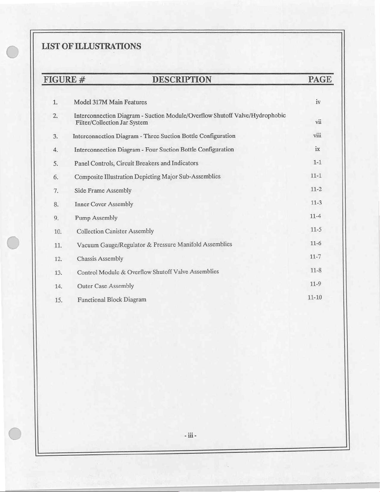
ILLUSTRATIONS
#
Model
317M
Main
Features
Interconnection
Filter/Collection
Interconnection
Interconnection
Controls,
Panel
Composite
Frame
Side
Cover
Inner
Assembly
Pump
Diagram - Suction
Jar
Diagram - Three
Diagram - Four
Circuit
Illustration
Assembly
Assembly
System
Breakers
Depicting
DESCRIPTION
Module/Overflow
Suction
Suction
and
Major
Bottle
Bottle
Indicators
Sub-Assemblies
Shutoff
Configuration
Configuration
Valve/Hydrophobic
PAGE
iv
vii
viii
ix
11
111
11-2
11-3
11-4
10.
14.
12:
13.
14.
15.
Collection
Vacuum
Chassis
Control
Outer
Functional
Canister
Gauge/Regulator
Assembly
Module
Assembly
Case
Block
Assembly
Overflow
&
Diagram
Pressure
&
Shutoff
Manifold
Assemblies
Valve
Assemblies
11-5
11-6
11-7
11-8
11-9
11-10
-这
-
Page 5
Hospital-Grade
He
Positive
Disposable
with
SJT
Cable
Pressure
Output
Filter
Plug
Port
s
Quick-Release
Collection
Jars
Voltage/Frequency
elector
ircuit
EMEA
Removable
ker
Breaker
Sel
Switcl
P
Control
ŞA
i
Module
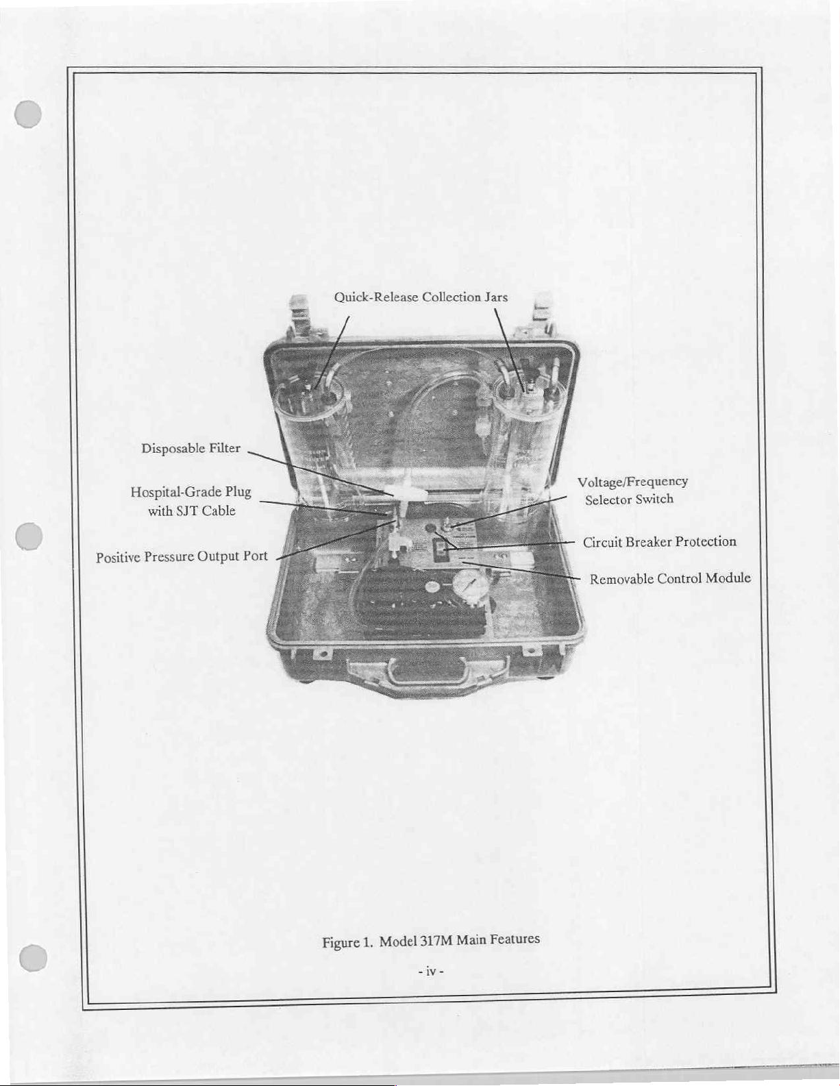
Figure
1,
Model
317M
iv-
Main
Features
Page 6
SHIPPING
Each
Model
lea.
Apparatus
Lea.
Control
2
ca.
Reusable
1
ca.
Assembly,
1
ea.
Hose,
1
ea.
Hose,
2ea.
Suction
2
ea.
Instruction
lea.
Filter,
CONTENTS
317M
is
shipped
Outer
Module
Collection
Overflow
Clear,
Clear,
Hose,
Manual,
Disposable,
with
the
following
Container
Canister
Shutoff
PVC,
6”
PVC,
Sterile,
Long
12"
Long
Clear
Operation
Hydrophobic/Bacterial
System
Valve
&
Service
contents:
ACCESSORIES
The
Accessories
number.
description
Accessories
and
Send
written
Telephonic
Part
Number
465-0005-00
540-0067-00
540-0068-00
703-0317-02
704-0317-02
820-0018-00
906-0317-01
quantity
orders:
LIST
List
contains
may
required.
purchase
201/882-1212
common
be
ordered
orders
to:
Impact
Р.О.
27
West
Description
Filter,
Disposable,
Hose,
Clear,
Hose,
Clear,
Assembly,
Assembly,
Tubing,
Instruction
Collection
Overflow
Suction,
Manual,
items,
required
direct
from
Instrumentation,
Вох
508
Fairfield
PVC,
PVC,
Place
Caldwell,
Hydrophobic
6"
Long
12"
Long
Canister
Shutoff
Sterile,
9/32"
Operation & Service
from
Impact.
New
Jersey
Valve
1D.
time
When
Inc.
X
6º
to
time.
ordering,
07006
Each
please
item
include
is
preceeded
the
by
part
its
part
number,
LIMITED
Permission
tract
for
COPYRIGHT
is
hereby
use
in a military
granted
service
RELEASE
to
the
training
Department
program
of
Defense
and other
to
reproduce
technical
training
all
material
programs.
furnished
under
this
con-
Page 7
CALIBRATION
This
device
operating
warrants
lowing
SERVICE
UNPACKING
Check
vious
within
specifications.
a
each
the
signs
this
should
shorter
καν
of
manual
period
cumulative
contents
shipping
before
NOTICE
be
incorporated
Calibration
between
period
μας
ο
of
ο.
of
the
shipping
damage.
If
attempting
into
a
regular
measurements
preventative
300
hours
of
o;
case(s) against
there
is
no
apparent
to
operate
preventative
should
maintenance
eration.
pi
the
Recommended
the
enclosed
sign
of
instrument.
maintenance
be
made
on
inspections.
packing
mechanical
a
A
maint:
list.
damage,
program
biannual
calibration
basis
'enance
ce
Examine
read
to
insure
compliance
unless
check
check
checks
the
the
significant
should
can
instrument
instructions
be
be
found
for
contained
usage
made
i
in
any
with
fol-
the
ob-
LOCATION
The
Model
317M
environment,
sheet,
plastic
tarp,
WARNINGS
This
equipment
Danger
Caution
nel
Do
Always
Do
Cleaning).
only.
not
not
-
Possible
-
Electric
operate
overflow
use
clean
OF
USE
is
a
transportable
user’s
should
etc.).
REGARDING
is
intended
explosion
shock
this
instrument
shutoff
collection
take
precautions
for
use
hazard
hazard,
canisters
do
prior
valve
with
device,
USE
by
qualified
if
used
not
to
reading
protect
to
abrasive
therefore,
and
protect
medical
in
the
remove
instrument
the
pump
cleansers
its
physical
this
device
personnel
presence
instructions
mechanism,
of
covers.
(See
area
of
by
covering
only.
flammable
Refer
contained
ROUTINE
use
will
vary.
it
with
a
anesthetics.
servicing
within
CARE
to
this
manual.
AND
MAINTENANCE
When
operated
protective
qualified
service
in
barrier
person-
section
a
wet
(small
ASSEMBLY,
ASSEMBLY:
INTERCONNECTIONS:
flow
Shutoff
Impact’s,
utilize
INTERCONNECTIONS
No assembly
Valve,
Hydrophobic
the
connection
is
required
The
following
instructions
Filter
AND
before
placing
interconnections
and
Collection
provided
this
by
Jar
the
INITIAL
device
into
are
required
System.
respective
When
ADJUSTMENTS
operation.
to
connect
using a collection
collection
the
jar
manufacturer.
Model
317M
system
to
its
other
Over-
than
Page 8
ASSEMBLY,
INTERCONNECTIONS
Hose,
3/8"
I.D. X 12"
Long
AND
Overflow
INITIAL
Shutoff
ADJUSTMENTS
Valve
(cont'd)
Collection
Hose,
Hose,
Canister
9/32" - 3/8"
(To
Patient)
3/8"
LD. X 12"
Vacuum
LD. X 6
Long
Inlet
#2
Long
=
ie
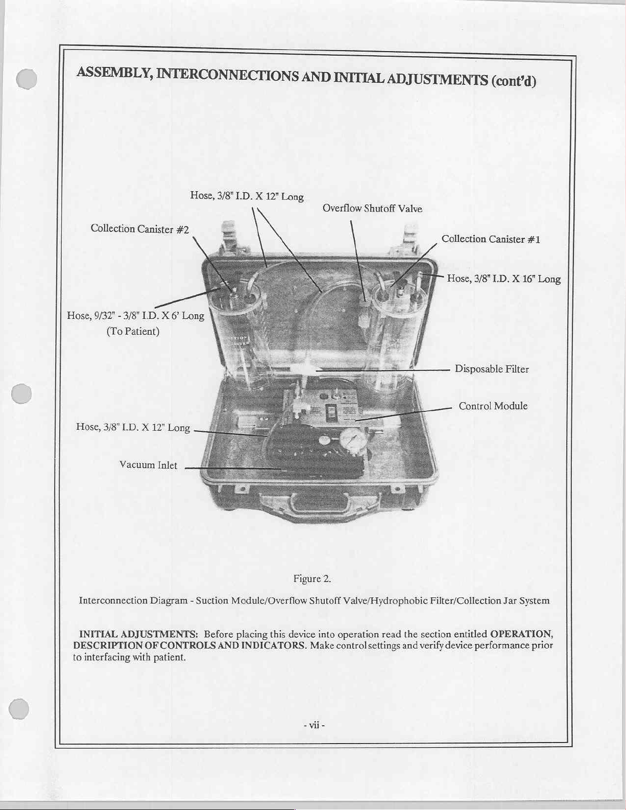
Interconnection
INITIAL
DESCRIPTION
to
interfacing
Diagram - Suction
ADJUSTMENTS:
OF
CONTROLS
with
patient.
Module/Overflow
Before
placing
AND
INDICATORS.
this
device
Figure
Shutoff
into
Make
-vii-
2.
Valve/Hydrophobic
operation
control
read
settings
Filter/Collection
the
and
verify
section
entitled
device
Jar
System
OPERATION,
performance
prior
Page 9
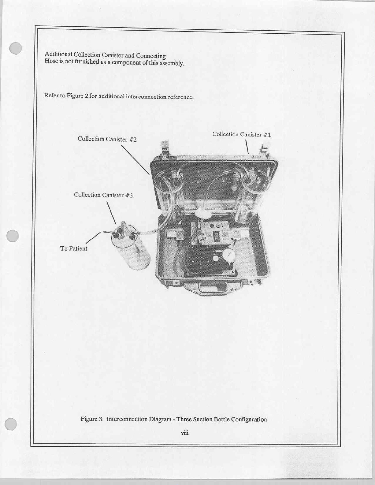
Additional
Hose
is
not
Refer
to
Figure
Collection
furnished
Collection
Collection
2
for
additional
Canister
as
Canister
and
a
component
interconnection
Canister
#3
Connecting
of
this
assembly.
reference.
#2
Collection
Canister
#1
To
Patient
Figure
3.
Interconnection
Diagram - Three
Suction
Bottle
Configuration
Page 10
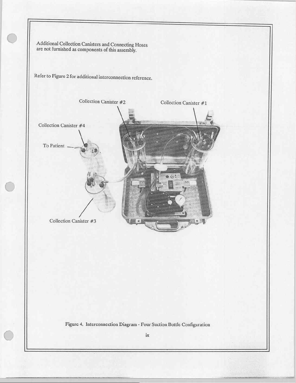
Additional
are
not
furnished
Refer
to
Figure
Collection
Collection
2
Canister
Canisters
as
components
for
additional
Collection
#4
and
Connecting
of
this
interconnection
Canister
Hoses
assembly.
reference,
#2
Collection
Canister
#1
Collection
Canister
Figure
#3
4,
Interconnection
Diagram - Four
ix
Suction
Bottle
Configuration
Page 11
SECTION L OPERATION
INTRODUCTION
The
Impact
Operating
The
Model
cuits, a dual-scale
lection
device
trol
module
ment.
This
suctioning.
OPERATION
Model
voltages
317M
canister
is
housed
and
is
device
Read
317M
and
frequencies
consists
vacuum
system;
intended
overflow
within.a
collection
instructions
the
is a self-contained,
for
115/230
of a control
gauge
structural
canisters
use
for
module
with
adjustable
shutoff
valve;
ABS
enclosure
are
rail
non-explosive
in
contained
mounted
within
general-purpose, Suction/Pressure
VAC,
50/60
HZ
are
"key
switch"
containing:
regulator,
hydrophobic/bacterial
atmospheres:
this
vacuum/pressure
and
featuring
with
latch-locks
quick
manual
pressure
for
before
port
filter
release
surgical
attempting
guides
apparatus
selectable
pump,
with
and
attachment
and
integral
to
procedures;
designed
for
control
overload
facilitate
to
and
protection; a dual
tubing.
carrying
oral,
operate
for
world-wide
power
The
handle.
removal
this
and
and
nasal
instrument.
field
use.
usage.
supply
cir-
col-
complete
The
con-
deploy-
tracheal
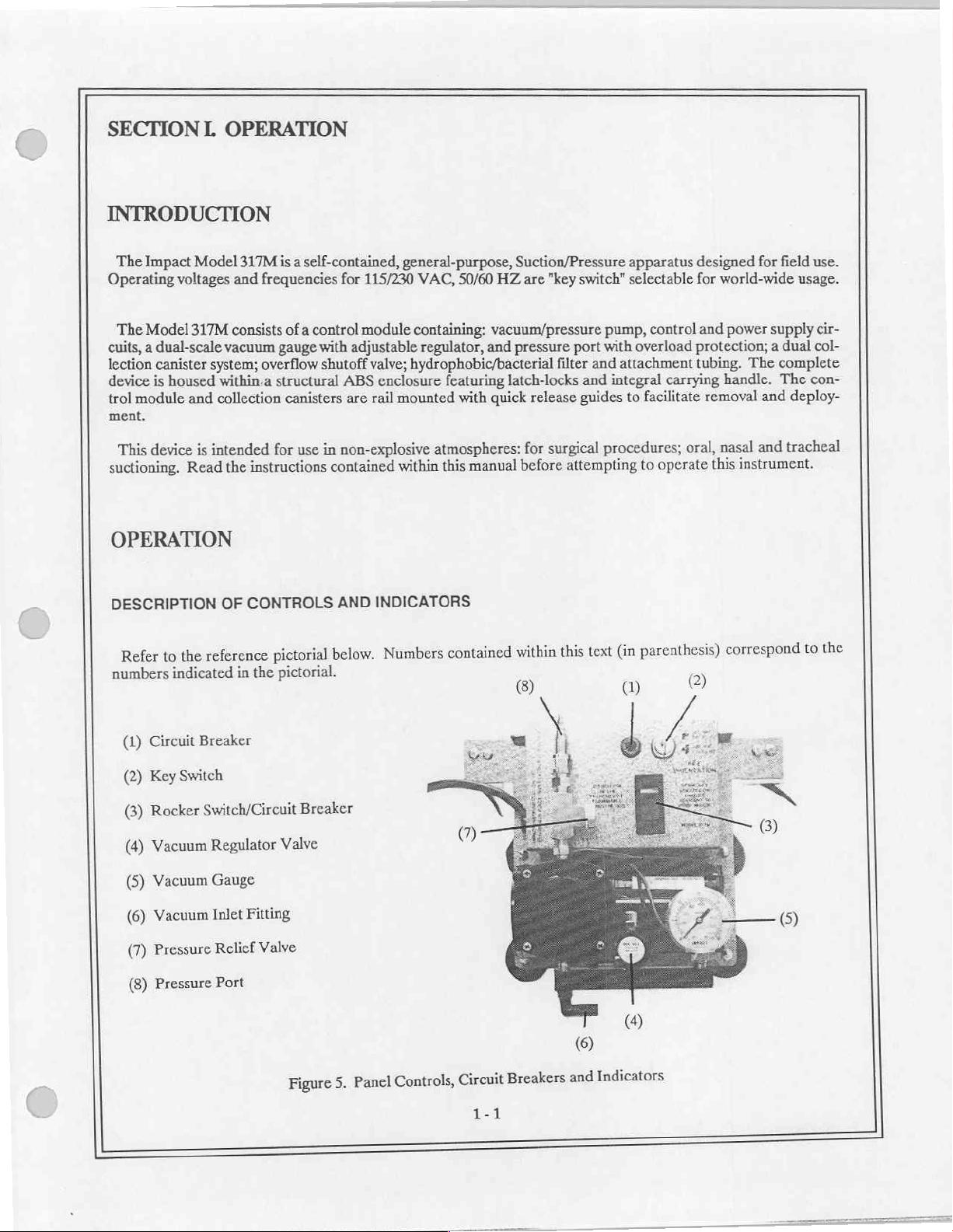
DESCRIPTION
the
to
Refer
numbers
(1)
(2)
(3)
(4)
Circuit
Key
Rocker
Vacuum
(5)
Vacuum
Vacuum
(6)
(7)
Pressure
(8)
Pressure
indicated
Switch
CONTROLS
OF
reference
Breaker
Switch/Circuit
Regulator
Gauge
Inlet
Relief
Port
pictorial
in
the
Fitting
Valve
pictorial.
Valve
AND
below.
Breaker
INDICATORS
Numbers
contained
within
(8)
this
text
parenthesis)
(in
0)
©
correspond
to
the
5.
Figure
Panel
Controls,
Circuit
1-1
Breakers
and
Indicators
Page 12
OPERATION
OPERATING
_
The
Model
is
selected
to
operation
start
and
SUCTIONING
1.
Verify
2.
Insure
properly
3.
Depress
4,
Adjust
vacuum
maximum
Gauge
POWER
317M
by
setting
within
stop
operation.
that
that
secured,
Rocker
Vacuum
tubing
level.
(5).
(cont’d)
SELECTION & STOPPING
is
designed
Key
Switch
the
220-240
Key
Switch
all
suction
fittings
going
Adjusted
in
Switch/Circuit
Regulator
to
the
to
(2)
VAC.
(2)
is
tubing
place
Valve
first
delivered
and
operate
to
the
The
set
to
correct
is
properly
as
shown
Breaker
(4)
stage
collection
on
115
VAC,
applicable
Rocker
secured
(Figure
(3)
to
vacuum
115
Switch/Circuit
operating
to
2),
to
"ON"
the
maximum
canister.
levels
50/60
HZ
VAC
or
230
voltage.
respective
and
no
kinks
position.
desired
Deliverable
continuously
are
or
230
VAC,
VAC
setting.
Breaker
fittings.
Verify
in
connecting
vacuum
vacuum
displayed
50/60
(3)
acts
level
HZ. The
Note:
as a master
that
collection
tubing.
by
"pinching"
levels
will
on
230
not
the
operating
VAC
settings
power
canister
and
exceed
scale
dual-
voltage
apply
switch
lids
holding
the
preset
Vacuum
to
are
the
applications
For
5.
warrant
which
tions
disposable
A
6.
mechanism
mechanism
filter
this
DO
7.
Verify
1.
Secure
2.
Depress
3.
connect
connect
2).
of
designed
is
filter.
block
NOT
that
tubing
Rocker
Always
canisters,
(Figure
flow
flow
discoloration
This
bypass
PRESSURE
require
which
suctioning
overflow
overflow
filter
and
and
membrane
its
Key
(not
mechanism
mechanism
which
collection
collection
retain
to
occlude
or
Switch
(2)
supplied)
Switch/Circuit
fast
greater
of
hydrophobic
both
is
canister.
canister
occurs,
bacteria
Pressure
the
set
is
to
down
pump
quantities
between
between
When
furthest
membrane
the
would
which
Port
correct
to
Pressure
Breaker
Port
(3)
times,
aspirate,
of
vacuum
vacuum
bacterial
and
multiple
from
(8)
operating
to
canisters
the
contacts
otherwise
during
(8).
position.
"ON"
first
utilize
utilize
and
pump
and
pump
provided.
is
are
patient
voltage.
(Figure
aspirate,
exhausted
be
suctioning.
collection
stage
canisters,
dual
collection
collection
used,
or
canister
This
connect
This
2).
following
into
canister
connected
canister.
furthest
connects
filter
filter
the
should
filter
cumulative
150
immediate
the
only.
series,
in
When
from
between
between
be
vicinity.
applica-
For
shown.
as
multiple
using
patient
the
the
the
replaced
of
hours
DO
over-
over-
when
use.
NOT
1-2
Page 13
OPERATION
PRESSURE
4.
DO
nect
the
sure
related
5. A Pressure
NOT
block
VACUUM
The
selected
vacuum.
holding
vacuum
play
during
(cont'd)
NOT
block
overflow
applications.
or
REGULATOR
Vacuum
by
rotating
Vacuum
the
vacuum
levels
operation
(cont'd)
or
occlude
mechanism,
Relief
Valve
occlude
Regulator
will
this
the
Vacuum
regulator
tubing
not
exceed
on
Vacuum
filter,
(7)
limits
valve.
Valve
(4)
Regulator
adjustments
going
to
this
preset
the
dual-scale
Inlet
Fitting
suction hose(s)
maximum
works
in
Valve
should
the
first
maximum.
Vacuum
(6), or
and
deliverable
conjunction
(4):
be
made
stage
collection
Gauge
suction
collection
pressure
with
clockwise
to
the
canister
Adjusted
(5).
lines.
canister(s)
to
the
Vacuum
to
increase
maximum
(canister
and
delivered
It
is
recommended
when
11
pounds
Gauge
vacuum;
desired
closest
vacuum
that
the
utilizing
per
(5).
counterclockwise
vacuum
this
square
Vacuum
level
to
"patient").
levels
will
device
inch
by
"pinching"
continuously
user
discon-
for
pres-
(PSI).
levels
to
Deliverable
DO
may
decrease
and
be
dis-
COLLECTION
ALWAYS
which
canisters,
Collection
agents
tants
OPERATOR
Before
performance.
1.
use
permanently
may
hydrophobic
canisters
chlorinated
or
please
note
Bushings:
placing
operating
Verify
JAR
SYSTEM
overflow
the
damage
filter,
may
hydrocarbons.
the
following
Collection
Hose
PERFORMANCE
Canister
Fittings:
device
this
power
shutoff
be
valve
vacuum
the
overflow
repeatedly
material
and
CHECKS
operation,
into
selections
provided
pump.
shutoff
sterilized
determine
To
content:
Covers:
the
115
at
unit
this
with
Vacuum
control
and
valve
ethylene
using
compatibility
Polycarbonate
Stainless
Neoprene
operator
230
or
Stecl
Rubber
can
VAC.
protect
to
is
tubing
module
dioxide
with
perform
suction
the
provided
Vacuum
commercially
various
for
Inlet
DO
gas.
operational
mechanism
interconnection
Fitting
use
NOT
available
checks
from
of
(6).
abrasive
cleanser/disinfec-
insure
to
overflows
collection
cleansing
proper
2.
Verify
continuous
operation.
1-3
Page 14
OPERATION
OPERATOR
3.
Test
4.
Insure
PERFORMANCE
the
vacuum
that
(cont'd)
regulator
all
hoses and
CHECKS
for
correct
fittings
are
(cont'd)
operation
properly
at
various
connected.
vacuum
settings.
Page 15
ROUTINE
CLEANING
NOTE:
disinfectant.
canister
to
avoid
II.
fectant, a mild
The
ment.
(1)
fully
module
Arail edge
to-guide
locked
Routine
With
and
shortly
risk
of
SERVICE,
©
Component
control
The
cam-locking
to
module
control
the
right.
or
canisters
view
interface
into
the
CARE
bacterial
DISASSEMBLY/ASSEMBLY).
spray
guide.
rail’s
AND
decontaminations
the
device operating,
thereafter
growth.
disinfectant
Removal
and
module
Each
To
lock,
can
discloses a concave
is
made
rectangular
MAINTENANCE
into
the
In
the
or
ethylene
collection
is
secured
guide contains a locking
slide
the
lever
slide
along
their
when
(1)
track.
which
vacuum
event
canisters
with
and
the
do
not
involve
simply
spray a small
inlet
of
of
an
aspirate
All
pump
oxide
gas.
may
be
two
(2)
cam-locking
to
the
left.
rails
for
repositioning
rectangular
convex
track
the
removal
amount
the
pump
head.
overflow,
head
components
removed
lever.
When
track. A guide
is
from
guides,
To
release
the
guide
or
"tipped"
into
removal.
of
aspirate
of
disinfectant
This
remove
their
edge
may
respective
each
collection
tension
lever
is
view
the
convex
the
can
be
effected
directly
should
be
performed
pump
head
assembly
be
sterilized
rails
for
canister
(unlock
in
its
discloses a convex
the
unlocked
track,
and
guide),
using a spray
into
the
collection
after
each
(SECTION
using a liquid
cleaning
is
position,
(2)
or
secured
slide
the
track.
the
guide
use
disin-
deploy-
with
one
the
lever
control
The
rail-
lever
is
©
Exterior
Periodically
trol
module,
facilitate
©
Control
UNPLUG
cloth
damp
Collection
Collection
Impact’s
cleansing
cleanser/disinfectants,
Case
or
when
collection
cleaning.
Module
POWER
suffice
will
Canisters
canister
reusable
agents
collection
or
Collection
Hose
Fittings:
Bushings:
applicable,
canisters,
CORD
systems
before
most
in
chlorinated
please
Canister
clean
overflow
cleaning
Disinfectant
cases.
should
be
canisters
hydrocarbons.
note
the
and
Covers:
the
exterior
shutoff
cleaned
may
following
valve,
control
or
repeatedly
be
material
Polycarbonate
Stainless
Neoprene
case
using a mild,
hydrophobic/bacterial
module.
spraying
disposed
To
DO
recommended
is
in
of
sterilized
determine
content:
Steel
Rubber
non-
NOT
accordance
using
compatibility
abrasive
filter
liguids
allow
regular
at
with
ethylene
cleanser.
and
to
their
gas.
oxide
with
Remove
any
stored
accessories
control
enter
intervals.
respective
commercially
instructions.
NOT
DO
the
module.
abrasive
use
available
con-
to
A
2-1
Page 16
ROUTINE
©
Collection
1.
Thoroughly
Collection
plunger
shown
The
tion.
reassembling.
knob
2.
Tubing
3.
Insure
4.
Orient
in
®
Overflow
overflow
Disinfectant
©
Hydrophobic/Bacterial
CARE
Canisters
clean
canisters
up
with
is
considered
that
all
collection
2.
Figure
Shutoff
shutoff
AND
(cont'd)
collection
are
held
one
hand
disposable
covers
and
canisters
Valve
valve
may
solutions
should
MAINTENANCE,
canister(s),
in
place
and
pull
and
parts
are
as
shown
be
disassembled
be
Filter
and
by
a
spring
the
canister
should
securely
in
Figure
diluted
according
fittings
be
fastened
and
after
loaded
forward
discarded
2
following
cleaned
to
CLEANING
each
use.
plunger.
with
following
after
cleaning,
using
their
To
the
other.
cleaning.
warm
respective
(cont’d)
quickly
each
soapy
remove
use.
Route
connecting
water
instructions.
either
or
a
canister,
tubing
mild
disinfectant
Dry
thoroughly
and
pull
the
filter
as
solu-
before
DO
NOT
attempt
replaced
hours
DO
port
As
come
MAINTENANCE
Routine
service.
1.
2.
siderably
3.
aspirate
4.
whenever
of
use,
NOT
bypass
allowed
or
filters
become
evident.
maintenance
Routine
Cleaning
Filter
checks - replace
or
following
Overflow
or
following
Operational
to
clean
it
becomes
whichever
this
filter.
accumulate
to
occluded
Filter
replacement
maintenance
checks - as
150
shutoff
valve - clean
150
checks - as
the
discolored
comes
first.
Its
intended
in
with
should
be
should
described
when
hours
hours
of
described
disposable
or
use
head.
pump
the
particulate
will
restore
performed
consist
above.
discolored,
of
cumulative
in
warm,
cumulative
in
OPERATOR
hydrophobic/bacterial
contacts
is
to
matter
device
on
of
contact
use,
soapy
use.
aspirate,
retain
during
performance
this
apparatus
the
following:
with
water
Dry
thoroughly
PERFORMANCE
bacteria
repeated
aspirate
or
with a mild
filter.
airflow
which
to
at
regular
occurs, airflow
before
This
item
is
impeded,
would
be
usages,
its
a
reduction
original
disinfectant
airflow
intervals
reassembling.
CHECKS.
is
disposable
or
following
exhausted
in
device
levels.
and
prior
performance
solution
and
150
through
airflow
to
being
diminishes
when
contacted
should
cumulative
the
pressure
will
be-
placed
into
con-
with
be
5.
Tubing
checks - replace
crimped,
cracked
or
worn
tubing
2-2
as
required.
Page 17
IN
CASE
OF
DIFFICULTY
Authorization
nor
does
Impact
servicing.
Impact
schematics.
mended
Customer
OPERATOR
Common
integrity
cessory
To
vacuum
vacuum
OPERATOR
will,
upon
Such
that
staff
Service
CORRECTIBLE
problems may
of
all
tube
item
or
isolate a problem,
jar
from
from
the
PROBLEMS
to
service
Instrumentation,
departments
members
Department.
the
#2
overflow
this
instrument
request,
connections,
Suction
jar
to
provide
are
attend a factory
PROBLEMS
be
quickly
Module
check
for
vacuum
#1,
shutoff
REQUIRING
tubing,
by
Inc.
assume
competent
encouraged
rectified
fittings,
by
testing
vacuum
valve
from
to
at
jar
the
SERVICE
other
than
any
responsibility
biomedical
to
contact
training
by
the
users.
and
for
vacuum
inlet
to
#1
Vacuum
course.
Should
control
of
the
Inlet
factory-trained
engineering
the
factory
Details
the
settings.
at
various
each
item,
vacuum
filter,
Fitting
and
and/or
liability
for
may
Model
One
locations.
tracing
from
(6).
assistance
be
317M
can
certified
departments
backwards
the
personnel
resulting
when
obtained
fail
to
operate
quickly
to
filter
by
isolate
the
will
from
such
with
service
needed
through
and
contacting
properly,
problems
the
overflow
not
be
given,
unauthorized
data
and
it
is
recom-
the
Impact
verify
the
to
an
ac-
system,
shutoff
i.e.
valve,
tests
the
If
contact
sary,
have
Please
request.
described
your
Model
the
Model
The
above
nearest
and
317M
not
do
Impact
Serial
Serial
operating
resolve
representative
Numbers
Number
an
ready
located
is
or
and
problem,
Impact
the
any
the
on
other
outer
service
Customer
pertinent
case
is
data
identification
required.
Service
Department
wish
you
label.
Should
include
to
(201)
your
in
be
882-1212.
servicing
neces-
service
Page 18

STORAGE
For
prolonged
and
out
of
should
be
The
Model
or
parts
Following
stabilize
LIMITED
Impact
for a period
of
manufacturing
is
tampered
SPECIFICATIONS
INFORMATION
storage
direct
sunlight.
low.
317M
may
replacements.
periods
to a temperature
Instrumentation,
of
of
WARRANTY
one
(1)
origin.
with,
misused
periods,
Storage
be
stored
extended
within
Inc.
warrants
year.
Accessories,
This
warranty
or
serviced
the
Model
temperatures
for
lengthy periods
storage
its
in
non-controlled
specified
this
which
is
neither
by
unauthorized
317M
should
should
of
time,
operating
instrument
by their
range
assignable
personnel.
be
stored
indoors.
range
between
without
environments,
(see
SPECIFICATIONS,
to
be
free
from
nature
are
consumable,
nor
transferable,
The
5'F
and
requiring
allow
the
all
defects
nor
environment
104F
(-15‘C
periodic
will
maintenance
Model
below).
in
materials and
be
warranted
does
it
to
317M
apply
should
sufficient
if
be
clean,
40‘C),
humidity
inspections
time
workmanship
only
for
defects
this
instrument
to
Vacuum:
Airflow:
Temperature
Controls:
Collection
Power:
Case:
Size:
Cube:
Weight:
Warranty:
SPECIFICATIONS
Capacity:
Operating
CONTAINED
Range:
550
mm/Hg
(22
31
Liters
Per
-29'C
to
60'C
Power
Switch - OFF/ON
Vacuum
1600cc x 2
Nominal
Structural
47cm
12
9.8
One
HEREIN
W
cu.
kg
(1)
ft.
(25
Adjust
115/230
x
ycar,
REPRESENT
inches/mercury)
Minute
(-20'F
ABS
18cm
lbs.)
(LPM)
to
VAC,
integeral
with
39cm
x
H
limited
140'F)
HZ
50/60
(18.5"
D
TYPICAL
carrying
x7"
W
DEVICE
handle
Hx
D)
15.5"
PERFORMANCE
Page 19

SECTION
II.
SERVICE
INTRODUCTION
The
information
personnel
iz
therefrom.
Impact
however,
in
travel,
The
lated
field
Should
Number
Number
trained
en
Instrumentation
travel
meal
Impact
matter.
Place,
factory
ready
is
contained
in
resulting
and
and
time
service
Allservice
West
Caldwell,
servicing
and
any
located
on
the
care
from
unauthorized
will
meal
costs
costs
facility
requests
become
other
the
outer
herein
is
and
servicing
provide
resulting
charged
encourages
may
New
Jersey 07006,
necessary,
pertinent
case
identification
intended
of this
servicing
service
to
be
training
therefrom
the
user
dialogue
addressed
201/882-1212.
or
data
you
only
for
use
product.
nor
will
at
shall
be
at
prevailing
from
user
to
the
technical
wish
assistance
to
include
label.
by
factory-trained,
The
manufacturer
it
be
held
liable
the
manufacturing
borne
by
the
rates.
service
Service
personnel
Manager,
is
required,
in
your
and
does
for
site
user.
Training
Impact
please
service
certified
not
any
injuries
at
no
towards
Instrumentation,
request.
personnel
authorize
or
schooling
at
the
rectifying
have
the
The
or
damages
charge
user’s
site
any
Model
Model
or
military
assume
incurred
to
will
service
Inc.,
27
317M
317M
any
users;
result
re-
Fair-
Serial
Serial
CAUTIONARY
Prior
to
servicing
HELPFUL
Before
not
Check
Insure
hydrophobic/bacterial
ment
from
attempting
accessory
the
that
the
to
Refer
the
of
Always
safeguard
the
vicinity
related,
integrity
all
circuitry.
NOTE
this
device,
HINTS
repair/calibrate
to
all
of
collection
filter
schematic
Always
your
of
active
insure
and
tubing
canisters
is
not
dirty
assembly
and
insure
personal
circuitry.
well
that
Key
instrument,
this
fittings.
properly
seal
or
clogged.
pictorials
integrity
the
when
being
Switch
(2)
is
please
tubing
that
Verify
that
and
trouble
when
ground
circuit
of
troubleshooting
set
for
the
take
is
overflow
shooting.
appropriate
moments
few
a
crimped
not
mechanisms
Isolate
correct
the
and
electronic
operating
insure
to
cracked
or
not
do
problem
the
mains
AC
circuitry.
Keep
voltage.
that
to
due
stick.
a
to
voltage.
jewelry
problem
the
fatigue.
Verify
that
functional
liquids
and
is
the
seg-
Page 20

DISASSEMBLY/REASSEMBLY
REQUIRED
Screwdriver,
Screwdriver,
3/8"
socket
3/8"
open
end
Pliers,
needle
Open
end
wrench,
Bench
vise
PUMP
screws
secured
down. The
head
pump
head
slotted
ment.
HEAD
Four
(4)
in
Once
the
with
Flapper
screw
head.
is
sometimes
screw which
Reinsert
10-32 X 1/2
order
pump
valves
which
TOOLS
slotted,
phillips
with
drive
wrench
nosed
with
smooth
to
access
head
four
(4)
are
flapper
valves
is
Removing
compressed
secures
and
medium
head,
handle
adjustable,
slotted
is
8-32 X 3/8
located
secured
these
tighten
size
medium
10"
jaws
cap
the
pump
removed,
phillips
inside
are
each
to a metal
screws
and
the
facing
the
slotted
size
head
screws
head
for
the
pump
flat
the
pump
held
in
disk.
should
prevents
flapper
screw
secure
cleaning
diaphragm
head
screws
head
and
place
by a small
Four
(4)
release
the
disk
valve.
which
the
the
pump
head
or
servicing
is
"clamps"
can
8-32 X 7/16 phillips
disk,
assembly
Set the
will
quickly
(see
Figure
accessible
be
rectangular
however, a gasket
flapper and
the
seen
from
"back
for
diaphragm
once
coming
out"
to
the
pump
9).
cleaning
the
head
flat
washer
flat
located
free.
its
rectangular
the
housing.
or
replacement.
in
place.
is
removed
and
head
screws
Should
disk
assembly.
Remove
and
6-32 X 3/16
fasten
between
this
washer
the
occur,
A metal
turned
slotted
this
disk
aside
these
upside
disk
to
and
pump
remove
for
the
four
disk,
bind
the
the
mo-
The
underside
sembled
To
sure
screw.
NOTE:
sure
head
CAUTION:
Pump
vacuum
by
reassemble,
that
the
Orient
Refer
ports.
in
place
head
and
of
the
removing
valves
Tightly
using
Test
components
pressure
its
align
lay
cach
washer
to
Figure 9 for
secure
the
for
disk
assembly
respective
the
fiber
flush on
vacuum
port
with
the
disk
four
(4)
must
functions
the
be
gasket
disk
the
proper
with
10-32 X 1/2
the
at
assembled
exposes a fiber
6-32 X 3/16
within
surface.
stamped
orientation
its
vacuum
and
the
four
slotted
and
negate
will
slotted
pump
Each
word
(4)
port
gasket
bind
head.
valve
"UP"
visible.
of
the
assembled
8-32 X 3/8
cap
head
reassembly
after
oriented
as
intended
and
second
head
screw
and
Secure a flapper
is
held
to
the
disk
Set
the
disk
phillips
shown
flat
screws.
prior
in
operation.
device
head
Figure
flapper
assembled
to
to
valve.
rectangular
valve
to
each
with a rectangular
disk
avoid
reversing
screws.
returning
9.
Mount
this
Deviation
This
valve
washer.
side
of
washer
within
the
vacuum
the
device
result
will
can
be
the
disk
making
and
slotted
the
pump
and
assembled
patient
for
reversal
in
disas-
head.
pres-
pump
use.
of
Page 21

DISASSEMBLY/REASSEMBLY
VACUUM
Disassembly
of
these
which
To
This
Place
disconnect
ly
disassembled
To
head
respective
CONTROL
GAUGE/REGULATOR
of
the
two
assemblies
are
secured under
disassemble,
will
prevent
the
reassemble,
in
the
pump
each
vise,
port.
MODULE
remove
damage
head
manifold
using
insure
using
Do
vacuum
contain
high
the
to
in
the
at
the
adjustable
that
minimal
not
reverse
(INNER
AND
gauge/regulator
tapered
torque
pump
chromed
vise
and
the
point
all
fittings
holding
port
CASE)
(cont'd)
PRESSURE
and
pressure
pipe
threads.
pressures
head
and/or
secure
where
wrench
are
force.
connections.
to
as
described
smooth
with
it
enters
and
vise
correctly
Refer
MANIFOLDS
manifolds
Caution
achieve
minimal
an
earlier. A vise,
surfaces.
holding
the
pump
(see
Figure
aligned
to
Figure
are
must
be
airtight
and
force.
head.
Each
11).
tightened
11
and
seal.
periodically
exercised
with
Using
manifold
insure
to
protective
an
on
each
that
each
required.
prevent
(smooth)
adjustable
component
manifold.
manifold
Most
components
breakage
jaws
is
open
end
may
be
Secure
is
secured
of
fittings
required.
wrench,
individual-
the
pump
to
its
The
Control
Pump
Assembly,
The
control
is
rail
Remove
The
remove
pump.
(unlock
in
edge
into
ASSEMBLY
Pump
bind
with
Set
tension
lever
A
to-guide
locked
PUMP
slotted
To
sembly
Module
To
module
the
its
unlocked
view
discloses a concave
interface
the
is
the
rail’s
Control
Assembly
screws,
head
entire
the
hand,
one
Pump
the
Assembly
access
any
is
secured
guide),
slide
position,
when
made
rectangular
Module
(see
Pump
remove
Assembly
Assembly
Figure
electrically
and
Assembly;
each
consists
of
with
the
the
(1)
track.
down,
of a Chassis
these
assemblies,
two
lever
control
and
convex
the
mechanically
is
9)
position
the
of
then
Assembly,
the
(2)
cam-locking
the
to
fully
module
rectangular
(Inner
connected
three
separate
can
track
Case)
via
Inner
the
mounting
Side
Frame
Control
guides.
right.
slide
track. A guide edge
"tipped"
is
as
mounted
an
automotive
the
Module
Each
lock,
To
along
into
the
to
on
which
in
directed
insulated
Case
screws
guide
slide
its
rail
the
the
Chassis
two-conductor
of
one
connector
Assembly,
must
be
removed
contains a locking
lever
the
for
repositioning
view
discloses a convex
convex
preceding
its
go
track,
Assembly
sides.
through
halves.
section.
automotive-grade
While
the
Inner
the
to
and
with
grasping
Chassis
Cover
from
the
lever.
left.
or
remoyal.
the
(2)
three
underside
Assembly
Outer
To
the
When
track.
guide
8-32
(3)
connector.
Pump
the
and
Case.
release
guide
The
rail-
lever
3/8
X
As-
the
into
is
Page 22

DISASSEMBLY/REASSEMBLY
PUMP
Service
tween
INNER
Pump
ASSEMBLY
NOTE:
To
To
The
lips
electrically
The
brown
Itis
acceptable
personnel
reassemble,
metal
surfaces
COVER
remove
pan
the
Assemblies
Inner
Cover
head
connected
Cover
Inner
from
wires
(cont'd)
should
reverse
and
ASSEMBLY
Inner
as
described
Assembly
screws.
Assembly
CB1;
to
separate
determine
the
above
are
neatly
Cover
Assembly
is
Remove
to
the
rest
can
the
and
the
which
procedure.
"dressed"
earlier
secured
these
of
the
electrically
be
"faston"
(cont'd)
automotive
method
out
(Figure
within
to
screws
circuitry
8),
this
the
Chassis and
to
disconnected
connected
connector
is
more
Insure
that
of
the
way.
it
is
necessary
section.
disengage
and
black
halves
prior
convenient.
the
automotive
to
remove
Side
the
by
white
Frame
Inner
Assemblies
Cover.
removing
wires
to
removing
connector
the
Control
The
"faston"
the
T1
from
the
wires
Module
with
four
Inner
Cover
connected
(refer
three
mounting
are
not
(Inner
(4)
4-40 X 5/16
Assembly
Electrical
to
"pinched"
Case)
white
black,
Schematic).
screws.
be-
and
phil-
remains
and
reassemble; connect
To
wires
and
secure
SIDE
FRAME
remove
To
Cover
The
screws.
separated
be
and
tor
Removal
reassemble;
To
the
to
the
Assemblies
Frame
Side
Remove
to
red
the
of this
Chassis
Assembly
each
with
the
four
ASSEMBLY
Assembly,
Frame
Side
as
described
Assembly
screws
these
electrically
blue
and
Assembly
connect
disconnect
wires
provides
each
and
to
wire
(4)
phillips
earlier
(Figure
7)
disengage
to
from
to
wire
secure
the
with
respective
its
pan
necessary
is
it
within
secured
is
the
assembly.
this
(refer
fan
service
access
respective
its
the
head
this
to
Side
four
location,
screws.
remove
to
section.
Chassis
the
Frame
Disconnect
Electrical
to
transformer
to
in-line
phillips
(4)
carefully
Control
the
Assembly
red
the
T1,
head
Four
the
carefully
screws.
Assembly.
Schematic).
connection,
pan
close
Module
four
by
(4)
and
bridge
Inner
the
(Inner
(4)
in-line
wires
black
rectifier
attach
Cover
Case),
X
4-40
"faston"
from
D1-4
the
avoid
to
Pump
phillips
5/16
connections
pump
the
and
Frame
Side
pinching
Inner
and
head
pan
must
connec-
capacitor
C1.
Assembly
Page 23

CALIBRATION
EQUIPMENT
1,
Vacuum
to
dampen
2.
Pressure
oscillations).
3.
Flow
PROCEDURES
NOTE:
1.
Vacuum
exposed,
a)
Connect
REQUIRED
Gauge,
needle
Gauge,
Meter
(Rotameter),
All
calibration
Tests:
even
slightly,
device
PROCEDURE
0
-
30"
Hg
(0
-
760
oscillations).
0
-
30
PSI,
+/-3%
0
-
40
tests
may
be
All
vacuum
to
to a live
tests
atmosphere.
A.C.
power
mmHg),
accuracy
LPM,
+/-3%
performed
must
be
The
pressure
source.
+/-
3%
or
better.
accuracy
with
device
performed
port,
accuracy
(A
liquid
or
better,
mounted
in
the
absence
however,
or
better.
filled
minimum
within
of
must
(A
gauge
its
air
flow.
remain
liquid
filled
is
preferrable
inlet
fitting
outer
case.
Insure
unblocked.
gauge
bore
that
to
dampen
1/4",
no
vacuum
is
preferrable
needle
port
is
b)
Insure
©)
Insure
proceeding
before
d)
Close
e)
Turn
f)
Connect
g)
The
reading.
mmHg.
titled
h)
at
between
IMPORTANT
cluded
far
tive
Allow
CALIBRATION
Verify
preset
vacuum
vacuum
in
excess
circuit
that
all
that
all
vacuum
power
vacuum
device
will
for
Allow
for
similar
maximum
NOTICE:
inlet
of
pump
breaker
tubing,
tubing
further
regulator
on.
vacuum
readings
vacuum
gauges
will
fittings
is
free
with
gauge
to
now
commence
stabilization
gauge
PROBLEMS.
between
levels
which
The
at
the
time
motor
capability.
trip
to
and
collection
from
kinks
calibration
valve
by
turning
patient
prevent
inlet
"pumping
gauge
of
tolerances
the
of
100,
can
be
additive.
vacuum
of
the
power
The
any
canisters
and
fatigue
verifications.
its
knob
fully
fitting
of
the
down"
and
final
in
vacuum
300
must
on
sequence
motor
and
reading.
mmHg
be
will
damage
reading
device
and
gauge
electrical
are
properly
cracks.
verify
gauge
"stall",
Replace
clockwise.
leftmost
drawing
that
If
and
to
verify
connected
can
result
temporarily
from
connected
all
collection
a
vacuum
reading
reading
device
the
test
gauge
linearity.
after
power
in a startup
draw
occurring.
and
tubing
exhibiting
canister.
as
evidenced
fact
in
is
below
is
vacuum
gauge.
Allow
is
applied
motor
excessive
tightly
to
equal
standards
Repeat
for
torque
current,
secured.
these
characteristics
by
the
vacuum
greater
or
see
this
tolerance
to
the
device.
requirement
and
gauge
500
than
section
procedure
differences
the
en-
An
oc-
that
is
protec-
Page 24

CALIBRATION
VACUUM
2,
posed,
side
a)
b)
c)
d)
tubing.
e)
f)
If
pressure
3.
Air
phere.
TESTS
Pressure
even
slightly,
circuit.
the
of
Connect
that
Insure
Connect
Insure
Turn
Verify
that
Insure
power
a
measurement
flow
DO
NOT
Test:
device
pressure
that
minimum
test:
PROCEDURES
(cont’d)
All
pressure
to
atmosphere.
live
a
to
fittings
all
gauge
pressure
tubing
on.
pressure
is
Air
flow
occlude
tests
must
Do
power
A.C.
secured.
tightly
are
to
pressure
gauge
connecting
is
rated
for
use
reading
below
10
PSI
measurements
any
ports
on
be
not
source.
port.
under
of 10
see
must
the
pressure
(cont'd)
made
in
the
block
or
occlude
tubing
section
is
pressure.
PSI.
Allow
entitled
be
taken
circuit
free
absence
the
from
fatigue
for
pressure
CALIBRATION
with
the
or
air
flow
of
air
flow.
pressure
or
gauge
vacuum
and
measuring
Insure
relief
valve
signs
of
tolerance
PROBLEMS.
pressure
instrument.
that
no
pressure
or
any
ports
cracking.
when
taking
circuits
on
the
Replace
final
exposed
port
is
ex-
vacuum
defective
reading,
to
atmos-
a)
Connect
b)
Remove
secured.
©)
Insure
that
tics.
d)
Connect
e)
Turn
power
f)
Verify a minimum
ing
is
below
30
IMPORTANT
diameter
imum.
restricting
of
at
Bends
effect
device
to a live
disposable
all
tubing
flow
meter
on.
free
LPM
see
NOTE:
least
1/4” so
in
tubing,
upon
and
flow.
A.C.
filter
from
is
free
to
the
patient
air
flow
section
All
connecting
as
not
the use
power
source.
circuit,
from
kinks
or
port
on
of
30
LPM.
entitled
to
CALIBRATION
tubing
unnecessarily
of
connection
Insure
fatigue
the
leftmost
Allow
and
fittings
restrict
elbows
that
all
tubing,
cracking.
collection
for
flow
meter
PROBLEMS.
used
flow.
Connecting
to
the
fittings
Replace
tolerance
with
the
flow
meter
and
any
tubing
canister.
when
measuring
tubing
should
collection
exhibiting
taking
final
flow
meter
lengths
also
should
be
avoided
canisters
these
must
are
characteris-
reading,
have
be
kept
as
each
tightly
If
read-
an
inner
to a min-
has
a
Page 25

CALIBRATION
CALIBRATION
1.
Vacuum
and
collection
vacuum
LY/REASSEMBLY
the
tings.
measurement
SEMBLY/REASSEMBLY
sure
collection
ly
regulating
If
these
steps
diaphragm
2.
Pressure
Replace
If
these
If
the
above
that
3.
Air
flow
mounted.
the
PROBLEMS
tests:
canister
valve
do
not
is
not
test:
defective
steps
do
test.
steps
diaphragm
test:
If
canisters.
Insure
PROCEDURES
If
insufficient
components.
is
closed
result
in
desired
instructions.
cracked
If
an
not
If
the
fail
an
Replace
that
or
worn.
insufficient
tubing
which
result
in
desired
pressure
to
result
in
instructions.
is
not
crimped
insufficient
defective
the
vacuum
vacuum
Replace
(turned
vacuum
Verify
that
Replace
pressure
is
crimped
pressure
reading
proper
Verify
or
air
flow
tubing
regulating
(cont’d)
readings
fully
exceeds
pressure
worn.
reading
are
all
defective
clockwise).
readings,
all
flapper
the
reading
or
readings,
10
that
Replace
is
which
valve
made,
tubing
Verify
remove
valves
are
pump
head
is
made,
cracked.
partially
PSI,
this
readings,
all
made,
is
is
remove
flapper
the
insure
crimped
closed
insure
the
which
that
the
pump
properly
gasket
insure
the
Verify
that
occlude
valve
requires
the
valves
are
pump
head
the
proper
or
cracked.
(turned
proper
is
crimped
the
pump
head
sealing
if
torn
or
proper
the
pump
the
replacement.
pump
properly
gasket
connection
Verify
fully
clockwise).
connection
or
cracked.
head
is
securely
as
described
and
tightly
cracked.
connection
head
pressure
head
as
described
sealing
if
torn
or
that
the
of
all
in
the
secured.
of
all
is
securely
relief
valve
and
tightly
cracked.
of
all
tubing,
pump
tubing,
Insure
mounted.
DISASSEMB-
tubing
head
fittings
that
Insure
and
mounted.
during
in
the
DISAS-
secured.
fittings
is
secure-
the
that
fit-
the
In-
and
If
these
steps
do
not
SEMBLY/REASSEMBLY
sure
that
the
diaphragm
result
in
the
instructions.
is
not
crimped
desired
Verify
or
worn.
air
flow
reading,
all
that
Replace
remove
flapper
the
pump
are
valves
head
the
pump
properly
gasket
head
sealing
if
torn
as
described
and
or
cracked.
in
the
secured.
tightly
DISAS-
In-
Page 26

CIRCUIT
P1,
CB1,
S1
115
or
230
VAC.
output.
incoming
DC
purpose
the
overloads.
cases,
device
CB1
AC
D1-4
and
C1
signal
suitable
is
to
vacuum/pressure
Waveforms
considerable
performance
DESCRIPTIONS
and
T1
represent a voltage
TI
is a dual-primary,
is a two-pole,
line,
represent a full-wave
for
maintain a continuous
and
voltage
leeway
multi-voltage
powering
pump
over a broad
the
motor.
measurements
has
been
range
(Refer
selection
power
circuit
bridge
pump
and
air
flow,
Circuit
have
given
as to
of
conditions.
breaker
to
the
circuit. SI
transformer
breaker/switch
rectifier
and
fan
motors.
during
operation,
CB2
***NOTE***
been
noted
what
constitutes
attached
rated
filter
M1
protects
at
various
schematic
is a Key
for
50/60
which
protects
capacitor
represents
within
the
rectifier
locations
an
acceptable
Switch
the
which
Hz
operation
the
for
converting
the
miniature
electronics
and
on
voltage
drawing).
allows
selection
with a nominal
"hot"
and
"neutral"
the
12
cooling
enclosure.
motor
circuits
the
schematic
value
in
of
sides
VAC
to a filtered
fan's
motor.
M2
represents
against
drawing.
order
to
maintain
nominal
12
VAC
of
the
Its
current
In
most
Page 27

PREVENTATIVE
Preventative
mance.
Preventative
If
monthly
If
monthly
VISUAL
1.
Inspection
be
replaced
2.
Check
3.
Check
4.
Check
PERFORMANCE
maintenance
These
inspections
maintenance
usage
usage
CHECKS:
of
as
necessary.
the
vacuum
the
disposable
collection
tubing,
MAINTENANCE
inspections
should
inspections
is
less
than
is
greater
canisters
CHECKS:
than
Visual
fittings
gauge
Hydrophobic
consist
50
hours - PMI
100
hours - PMI
checks
should
and
collection
for a "zero
for
chips
Performance
should
of
both
(PMI)
bimonthly.
include,
area"
Filter
or
cracks
checks
INSPECTIONS
be
incorporated
visual
and
performance
should
canisters
reading
for
be
made
monthly.
but not be
for
cracks,
when
discoloration.
in
bottle,
for
should
on a routine
as
follows:
limited
crimps,
the
device
Replace
worn
or
include,
but
basis
checks,
to:
leakage
is
turned
if
discolored.
loose
fitting
not
be
to
insure
and
cleaning
and
general
off.
lids.
limited
proper
Replace
to:
device
when
wear.
as
perfor-
warranted.
They
should
required.
1.
Check
Check
2.
OPERATION
3.
Check
4.
Check
CLEANING:
portion
of
tactile
feel
and
various
the
cam-locking
this
operating
portion
Overflow
Refer
manual.
of
to
guides
operation
modes
this
manual).
Shutoff
for
ROUTINE
the
of
switches
(refer
Valve.
Insure
attachment
CARE
and
the
to
that
the
and
detachment
MAINTENANCE
AND
controls.
OPERATOR
ball
float
PERFORMANCE
does
not stick
operation.
"CLEANING"
and
CHECKS
is
debris
section
free.
the
in
section
OPERATION
in
the
Page 28

TROUBLESHOOTING
SYMPTOM:
Check
Disconnect
SYMPTOM:
Verify
voltages
ly
secured.
SYMPTOM:
Check
for
correct
clockwise.
SYMPTOM:
Check
for
active
M2
proper
at
T1,
D1-4, and
tubing
seal,
for
overload
No
power.
(live)
mains
at
its
automotive
Inadequate
Key
Switch
No
vacuum
connections
Insure
that
Circuit
breaker
at
M1
GUIDE
line.
connector
power.
positioning
CB2
to
determine
or
weak
for
crimps
pump
head
CB2
and
M2,
Reset
CB1
then
to
the
correct
if
pump
vacuum.
and
cracks.
is
properly
trips.
by
disconnecting
and/or
recheck
line
motor
Insure
secured.
CB2.
Check
voltages
voltage.
is
overloading
fittings
Check
each
motor
for
proper
to
see
if
pump
Disconnect
circuit.
are
properly
to
see
if
vacuum
individually
voltages
is
overloading
M2
at its
Insure
secured.
regulating
to
isolate
at
T1,
D1-4,
circuit.
automotive
that
pump
head
Check
collection
valve
problem.
M1
and
M2.
connector,
is
proper-
canisters
is
turned
fully
test
SYMPTOM:
Check
for
Circuit
defective
breaker
transformer
CB1
trips.
T1,
bridge
rectifier
D1-4
or
capacitor
C1.
10-1
Page 29

TECHNICAL
NOTE:
Refer
DOCUMENTATION
to
applicable
Bill
Of
e
Material
Collection
for
Part
Number
Canister
description.
Assembly
Outer
Case
Overflow
Assembly
Valve
Assembly
Shutoff
Side
Pressure
Pump
Assembly
Frame
Manifold
Assembly
Assembly
Vacuum
Gauge/Regulator
has
Inner
Module
my
Cover
Control
Assembly
Assembly
Sub-Assemblies
Composite
Figure
6.
Illustration
Depicting
11-1
Major
Page 30

(9)
(10)
@
# Part
Number
043-0001-00
099-0009-02
305-0001-00
322-0001-00
334-0012-00
DURADO
340-0002-00
#
Part
7
340-0014-00
8
346-0440-03
9
346-0632-01
10
352-0632-10
11
374-0002-00
12
374-0009-00
See
Bill
aa
Number
of
Material
0
#
Part
Number
B
374-0016-00
14
416-0002-00
15
422-0316-11
708-0002-00
704-0316-02
Figure
7.
for
complete
Side
11-2
Frame
Part
Number
Assembly
Description,
Page 31

(3)
@
(1)
(5)
(2)
(4)
#
PartNumber
1
081-0006-00 5 374-0001-00
2
081-0007-00 6 374-0003-00
3
131-0007-00 7 416-0316-11
4
305-0001-00
#
See
Part
Bill
Number
of
Material
704-0316-03
Figure
8.
Inner
for
complete
Cover
11-3
Part
Number
Assembly
Description.
Page 32

(4)
0)
(3)
Ter
|
(5)
Oa
Number
Part
#
1
660131
2
633439
3
617045
4
621102
5
654129
6
625141
7
625109
8
654649
9
608148
10
625160
CAUTION:
reassembly
after
patient
for
assembled
be
Incorrect
of
Vacuum
cause
device
Pump
Gasket
Valve
Flapper
Valve
Screw,
Screw,
Hold
Diaphragm
Screw,
for
Test
prior
Pump
use.
oriented
and
reassembly
and
will
Pressure
malfunction,
Ex
Description
Head
Keeper
Valve
Plate
Valve
Plate
Pump
Head
Down
Plate
Valve
Keeper
Vacuum
at
vacuum
returning
to
head
result
Port
this
components
shown
as
in
the
functions
i
moh
Port
device
must
above.
reversal
and
PRESSURE
PORT
|
|
|
|
|
@
=—
5
TE
|
“E
©
©
@
a
#
Part
Number
1
016-0004-00 3 099-0010-02 5 705-0316-01
2
041-0002-00 4 704-0305-02
#
See
Part
Number # Part
Bill of
Material
704-0316-04
Number
Figure
for
complete
9.
Pump
11-4
Part
Assembly & Pump
Number
Description.
Head
©
Page 33

TO
(2)
a
(13)
#
Part
Number
1
016-0317-11
2
340-0025-00
3
340-0027-00
4
357-1032-05
5
365-0003-00
#
PartNumber
6
370-0002-00
7
392-0014-00
8
404-0316-21
9
404-0900-11
10
416-0317-11
See
Bill
of
Material
#
Part
Numbe
11
416-0317-21
12
540-0066-00
13
602-0001-00
704-0305-02
Figure
10.
r
fo:
r
complete
Collection
Canister
11-5
Part
Number
Assembly
Description.
Page 34

#
Part
Number
1
315-0003-00
2
325-0305-05 5 480-0048-00
3
470-0001-00 6 480-0058-00
#
Part
Number
4
480-0038-00
#
Part
Number
7
480-0065-00
See
Bill
of
Material
#
PartNumber
1
480-0057-00 3 480-0103-00 5 480-0105-00
2
480-0100-00 4 480-0104-00 6 490-0003-00
#
See
Part
Number
Bill of
Material
704-0305-02
(2)
#
Part
Number
705-0316-01
for
complete
for
complete
Part
Part
Number
Number
Description.
Description.
Figure
11.
Vacuum
Gauge/Regulator & Pressure
11-6
Manifold
Assemblies
Page 35

(11)
(8)
(23)
(9)
(14)
(2)
(7)
(10)
(6)
(4)
0
NE
|
(3)
24)
(5)
(13)
25)
(27)
eo
eu 62
(15)
(22)
(18)
(20)
08)
65)
#
Part
Number
016-0020-00
023-0007-00
047-0005-00
252-4786-31
305-0001-00
334-0012-00
346-0440-03
346-0632-01
VAIANALNA
346-1032-01
10
346-1032-05
11
352-0632-10
#
PartNumber # Part
12
358-0440-05
13
358-1032-03
14
358-1032-10
15
374-0001-00
16
374-0002-00
17
374-0014-00
18
376-0020-00
19
404-0316-11
20
404-0900-151
21
414-0317-11
22
450-0006-00
See
Bill of
Material
(21)
Number
23
602-0001-00
24
606-0001-00
25
700-0316-01
26
700-0316-02
27
700-0316-04
28
700-0316-05
29
700-0316-06
30
700-0316-07
31
700-0316-08
32
700-0316-09
33
700-0316-10
704-0317-01
Figure
12.
for
complete
Chassis
11-7
(26)
Part
Number
Assembly
Description.
Page 36

#
PartNumber
1
352-0832-06 3 704-0316-02 5 704-0316-04
2
358-0440-05 4 704-0316-03 6 704-0317-01
#
Part
Number # Part
1
340-0019-00 3 820-0016-00
2
475-0002-00 4 820-0034-00
#
See
See
Part
Number
Bill
of
Number
Bill of
Figure
#
Material
Material
13.
Control
Part
Number
703-0316-02
704-0317-02
Module & Overflow
for
complete
for
complete
Part
Number
©
oi
(2) — *
Part
Number
Shutoff
Valve
Description.
ο.
Description.
Assemblies
(4)
11-8
Page 37

©
(14)
OM
(10)
|
δα
(4
©
©
an
©)
(15)
#
Part
Number # Part
1
325-0317-01 6 346-1032-01
2
334-0029-00 7 358-1032-07
3
338-0005-00 8 376-0031-00
4
338-0006-00 9 378-1032-08
5
340-0011-00
10
Number # Part
394-0004-00
Number
11
402-0316-11
12
450-0006-00
13
602-0001-00
14
900-0002-00
15
900-0003-00
06)
03)
(6)
(12)
=
See
Bill of
Material
703-0317-01
Figure
14.
Outer
for
complete
11-9
Case
Part
Number
Assembly
Description.
Page 38

POWER
SELECTION
115
VAC-
50/60
230
VAC
HZ
|_|
12
VDC
FAN
PUMP/
MOTOR
RELIEF
PRESSURE
PORT
VACUUM
REGULATOR
HYDROPHOBIC
FILTER
OVERFLOW
VALVE
|
—__>
PATIENT
Figure
15.
Functional
11-10
COLLECTION
Block
Diagram
SHUTOFF
VALVE
CANISTER
SYSTEM
Page 39

1
701-0317-01
1
WL702-0316-01
1
703-0316-02
1
703-0317-01
2
703-0317-02
1
704-0305-02
1
704-0316-02
1
704-0316-03
1
704-0316-04
1
704-0317-01
1
704-0317-02
1
705-0316-01
1
802-0317-01
Assembly,
Wire
List
Assembly,
Assembly,
Assembly,
Assembly,
Assembly,
Assembly,
Assembly,
Assembly,
Assembly,
Assembly,
Assembly,
TON
Final
Mechanical
Case,
Inner
Case,
Outer
Collection
Vacuum
Side
Canister
Gauge/Regulator
Frame
Cover, Inner
Pump
Chassis
Assembly,
Manifold,
Accessory
Overflow
Pressure
Kit
Shutoff
Valve
Dw NUMBER
COMP.
PL701-0317-01
WL702-0316-01
PL703-0316-02
PL703-0317-01
PL703-0317-02
PL704-0305-02
PL704-0316-02
PL704-0316-03
PL704-0316-04
PL704-0317-01
PL704-0317-02
PL705-0316-01
PL802-0317-01
DES.
800-0317-00
MASTER
BILL
MATERIALS
OF
MODEL
317
o
1
1
LES
11-11
==
==
SET
SE
z
A
Page 40

'Y
PART
NUMBER
DES
COMP.
DES.
1
465-0005-00
1
540-0067-00
3
540-0068-00
1
703-0316-02
1
703-0317-01
2
703-0317-02
Filter,
Hose,
Hose,
Assembly,
Assembly,
Assembly,
Disposable,
6”
Long,
12”
Hydrophobic/Bacterial
Clear,
Long,
Clear,
Case,
Inner
Case,
Outer
Collection
PVC
PVC
Canister
PL703-0316-02
PL703-0317-01
PL703-0317-02
701-0317-01
ASSEMBLY,
FINAL
MECHANICAL
11-12
MODEL
317
ο
LES
1
Page 41

RUN
COLOR
1
2
3
4
5
6
7
SLD-(AWG)-STR
Blk
Blk
Bm
Red
Red
Og
LENGTH
18
18
18
18
18
18
(“)
STRIP
11/2
63/4
111/2
71/2
71/2
10
1/2 3/8
318
318
3/8
3/8
3/8
(”)
TIN
ORIGIN
У
Ti-Primary
(1)
DI-4
(-)
(5)
081
(2)
CB2 3/8
(2)
082
(5)
D1-4
(+)
STRIP
CT
3/8
3/8
318
3/8
3/8
(")
TIN
У
Ti-Primary
(3)
M2
Y
Ti-Primary
(3)
ML
(3)
M2
(5)
082.
DESTINATION
CT
8
Grn
9
Grn
10
Blu
11
ASSEMBLY
WL702-0316-01
NOTES:
Blue,
=
(1)
Blue,
=
(2)
(3) = Red,
(4) = Red,
(5) = Red,
.250,
.187,
.250,
18
18
18
Fully
.250,
Fully
.250,
Fully
Fully
Fully
Unspecified
WIRELIST
3
7
63/4
Insulated
Insulated
Insulated
Insulated
Insulated
Female
Female
Female,
Female.
Female.
terminal material
318
318
3/8
(Both
(Both
Nylon.
Y
Y
(1)
wires
wires
be
may
MODEL
Ti
Secondary
Ti
Secondary
DI-4
(-)
crimped
crimped
vinyl
316/317
same
to
same
to
nylon.
or
3/8
3/8
3/8
terminal).
terminal).
LES
0
(5)
(5)
(3)
D1-4
D1-4
ML
1
(AC)
(AC)
1
©
11-13
Page 42

QTY
PART
3
352-0832-06
8
358-0440-05
NUMBER
Serew,
Screw,
DESCRIPTION.
Bind Head,
Pan
Head,
Phillips,
Slotted,
8-32 X 3/8
4-40 X 5/16
DWG.
NUMBER
COMP.
DES.
704-0316-02
704-0316-03
704-0316-04
704-0317-01
ыыны
Assembly,
Assembly,
Assembly,
Assembly,
Side
Cover,
Pump
Chassis
Frame
Inner
PL704-0316-02
PL704-0316-03
PL704-0316-04
PL704-0317-01
703-0316-02 O ASSEMBLY,
CASE,
INNER
11-14
MODEL
316
o
Page 43

QTY
A,
1
a:
2
4
4
5
2
5;
12
7
2
1
PART
325-0316-02
325-0317-01
334-0029-00
338-0003-00
338-0004-00
338-0005-00
340-0011-00
346-1032-01
358-1032-07
376-0031-00
378-1032-09
394-0003-00
402-0316-11
NUMBİ
Label,
Label,
Clip,
Rivet,
Rivet,
Rivet,
Bushing,
Nut,
Screw,
Washer,
Standoff,
Hinged
Case,
Keps,
DESCRIPTION
P/S,
Instructions
Metal,
Retaining
ABS
Pop,
#4
Pop,
#4
Pop,
#4
Rolled
10-32
Phillips,
Flat,
Self-Clinching,
Lid
Support
I.D.
Collar,
Pan
Aluminum,
#10
Head,
1/8”
10-32 X 7/16
I.D.
Female,
10-32 x 9/16
DWG.
NUMBER | COMP.
C325-0316-02
B325-0317-01
DES
€
4
As
Req
2
1
703-0317-01
450-0006-00
602-0001-00
900-0002-00
900-0003-00
ASSEMBLY,
Suction
Sealant,
Rail,
Rail,
CASE,
Cup,
3”
15
OUTER
Foot,
Silicone,
Long
1/2”
w/10-32 X 3/8"
Rubber,
Long
RTV
MODEL
Stud
317
1
LES
A
1
ο
=
SSeS
11-15
ーーーーーー
Page 44

QTY
PART
NUMBER
DESCRIPTION
DWG.
NUMBER
COMP.
DES.
As
1
2
1
2
1
1
1
1
1
1
1
2
Req
016-0317-11
340-0025-00
340-0027-00
357-1032-05
365-0003-00
370-0002-00
392-0014-00
404-0316-21
404-0900-11
416-0317-11
416-0317-21
540-0066-00
602-0001-00
Tubing,
Grommet
Gasket,
Serew,
Serew,
Spring,
Knob, Pull,
Bracket,
Bracket,
Cover,
Cover,
Elbow,
Sealant,
Clear,
P/S
Phillips,
Shoulder,
Compression
Mounting,
Guide
Top
Bottom
S/S
Silicone
Lexan, 9 1/4”
Flat
Head,
Aluminum
w/10-32
Female
Collection
Rubber,
Long
10-32 X 5/16
Insert
Canister
RIV
B016-0317-11
B365-0003-00
C404-0316-21
B404-0900-11
B416-0317-11
B416-0317-21
703-0317-02
|
ASSEMBLY,
COLLECTION
CANISTER
11-16
MODEL
317
Page 45

QTY
PART
1
315-0003-00
1
325-0305-05
1
470-0001-00
1
480-0038-00
1
480-0048-00
1
480-0058-00
1
480-0065-00
NUMBER
DESCRIPTION
Vacuum
Gauge,
1/8"
NPTM
Label,
Manifold,
Valve,
Nut,
Nipple,
Elbow,
Valve
Chrome,
Chrome,
Close,
Polyethylene,
3/8"
I.D.
2
1/4”
0.D.,
Gauge/Regulator
Ball
Seat,
1/8”
1/8”
NPTF,
Modified
Chrome,
Tube
1/8"
Black,
Bottom
NPTM
NPTM,
1/8”
NPTM
Mounting,
Modified
to
DWG.
NUMBER
|
COMP.
DES.
ο
ο
704-0305-02
ионов
|
ASSEMBLY,
=
VACUUM
GAUGE/REGULATOR
=
11-17
MODEL
305
E
LHS
e
1 1
Page 46

QTY
PART
1
043-0001-00
1
099-0009-02
4
305-0001-00
1
322-0001-00
2
334-0012-00
1
340-0002-00
1
340-0003-00
6
346-0440-03
4
346-0632-01
4
352-0632-10
2
374-0001-00
374-0009-00
1
374-0016-00
NUMBER
DESCRIPTION
Fan,
12VDC
Plug,
CMM/F, 2 Cond,
Cable
Tie,
Miniature
Grill,
Fan
Clip,
P/S,
for
Bushing,
Bushing,
Nut,
Nut,
Screw, Bind
Terminal,
Terminal,
Nylon
Terminal,
Strain
Strain
Self-Clinching,
Keps,
6-32
Fully
Fully
Insulated,
3/8"
Relief,
Relief,
Head,
Slotted,
Insulated
Insulated
(Red
Hire
for
for
4-40
Red,
Wire
Insulated)
Bundle
SPT-1
SJT
Wire
6-32 X 5/8
Female,
Male,
Red,
#10
Ring
Wire
Red,
.250W,
.250W
DWG.
NUMBER
COMP.
ML
DES.
1
416-0002-00
1
422-0316-11
1
708-0002-00
704-0316-02
|
Cap,
Panel,
Cable,
ASSEMBLY,
Vented,
Hospital-Grade
FRAME
SIDE
Black
Side
Frame
Molded,
16/3
Plug
SJT
w/Molded
MODEL
316
C422-0316-11
LHS
A
PL
1
1
Page 47

m
{
=
PART
2
016-0004-00
1
981-0006-00
1
081-0007-00
1
131-0007-00
6
305-0001-00
1
374-0001-00
2
374-0003-00
ュ
416-0316-11
1
700-0316-03
1
700-0316-11
NUMBİ
DESCRIPTION
Tubing,
Circuit
Circuit
Switch,
Cable
Shrink,
Breaker,
Breaker,
Key,
Tie,
Terminal,
Terminal,
Cover,
Jumper,
Jumper,
Top,
Black,
White,
3/16”
7A,
4A,
SPDT
Miniature
Fully
Insulated
Fully
Insulated
Inner
15
1/2“
15
1/2"
I.D.
SPST
DPST
Long
Long
X 1“
Long
Female,
Female,
Red,
Red,
.250W
.187W
DWG.
NUMBER
COMP.
082
CB1
B416-0316-11
WL702-0316-01
WL702-0316-01
704-0316-03
O
ASSEMBLY,
COVER,
INNER
MODEL
316
o
1
1
LHS
11-19
Page 48

QTY
PART
2
016-0004-00
1
041-0002-00
1
099-0010-02
1
704-0305-02
1
705-0316-01
NUMBER
DESCRIPTION
Tubing,
Pump,
Plug,
Assembly,
Assembly, Manifold,
Shrink,
3/16”
Vacuum
CMM/F, 2 Cond,
Vacuum
Gauge/Regulator
Pressure
I.D. X 1”
(Black
Wire
Long
Insulated)
NUMBER
COMP.
M2
PL704-0305-02
PL705-0316-01
DES.
O
704-0316-04
ASSEMBLY,
PUMP
316
MODEL
0
LES
1
1
>
11-20
Page 49

QTY
PART
2
016-0020-00
1
023-0007-00
1
047-0005-00
1
252-4786-31
4
305-0001-00
1
334-0012-00
4
346-0440-03
1
346-0632-01
3
346-1032-01
4
346-1032-05
ュ
352-0632-10
2
358-0440-05
4
358-1032-03
2
358-1032-10
NUMBER
DESCRIPTION
Tubing,
Transformer,
Diode,
Capacitor,
Cable
Clip,
Nut,
Nut,
Nut,
Nut,
Screw,
Serew,
Screw,
Serew,
Teflon
Sleeving,
Power,
Bridge
Rectifier,
Aluminum,
4700
ufd,
25V
Tie,
Miniature
P/S,
For
Self-Clinching,
Keps,
6-32
Keps,
10-32
Cap,
10-32
Bind
Head,
Pan
Head,
Pan
Head,
Pan
Head,
#18
Dual
Primary
12A,
Electrolytic,
3/8"
Wire
Bundle
4-40
Slotted,
Phillips,
Phillips,
Phillips,
AWG
50
PIV
6-32 X 5/8
4-40 X 5/16
10-32 X 3/16
10-32 X 5/8
DWG.
NUMBER
COMP.
DES.
mn
D1-4
οι
5
374-0001-00
2
374-0002-00
4
374-0014-00
8 © 376-0020-00
704-0317-01
ASSEMBLY,
Terminal,
Terminal,
Terminal,
Fully
Fully
Fully
Nylon
Washer,
Lock,
CHASSIS
Insulated
Insulated
Insulated
Internal
Tooth,
Female,
Female,
Female,
Red,
Blue, .250W
Red,
#10
317
MODEL
„250W
.250W,
A
LES
1
2
x
nisi
-
===
NT
OMM
Page 50

=
@
As
As
QTY
1
2
1
4
Reg
Reg
1
1
1
1
1
1
1
1
1
PART
NUMBER
404-0316-11
404-0900-151
414-0317-11
450-0006-00
602-0001-00
606-0001-00
700-0316-01
700-0316-02
700-0316-04
700-0316-05
700-0316-06
700-0316-07
700-0316-08
700-0316-09
700-0316-10
DESCRIPTION
Bracket,
Bracket,
Chassis
Suction
Sealant,
Silicone
Jumper,
Jumper,
Jumper,
Jumper,
Jumper,
Jumper,
Jumper,
Jumper,
Jumper,
Cup,
Black, 1 1/2"
Black, 6 3/4“
Brown,
Red, 7 1/2”
Red, 7 1/2”
Orange,
Green,
Green,
Blue, 6 3/4”
Side
Frame
Guide,
2-Hole
Foot,
Silicone
Grease
11
10
3”
7"
w/10-32
Rubber,
Long
Long
1/2”
Long
Long
Long
1/2"
Long
Long
Long
Long
Stud
RTV
DWG.
NUMBER
B404-0316-11
B404-0900-151
C414-0317-11
WL702-0316-01
WL702-0316-01
WL702-0316-01
WL702-0316-01
WL702-0316-01
WL702-0316-01
WL702-0316-01
WL702-0316-01
WL702-0316-01
COMP.
DES.
€
704-0317-01
O
ASSEMBLY,
CHASSIS
11-22
MODEL
317
A
Ls
2
2
Page 51

QTY
PART
1
340-0019-00
1
475-0002-00
1
820-0016-00
2
820-0034-oo
NUMBER
DESCRIPTION
Bushing,
Ball,
Float
Tube
Cap,
Tube
Shoulder
DWG.
NUMBER
COMP.
DES.
704-0317-02
ASSEMBLY,
OVERFLOW
SHUTOFF
11-23
VALVE
MODEL
317
o
LES
1
1
Page 52

QTY
PART
1
480-0057-00
480-0100-00
480-0103-00
480-0104-00
480-0105-00
pere
1
490-0003-00
NUMBER
DESCRIPTION
Nipple
Adapter,
to
1/4"
NPTM
Tee,
Modified,
Hose
Barb,
Nut, Hex,
Adaptor,
Valve,
Body,
Relief,
Hex,
Chrome
Chrome,
Chrome,
Chrome,
Pressure,
Chrome,
Tapered
#1240
1/4”
11
1/8”
to
#1240
NPIM
PSI
NPTM
to
Male
#1240
DWG.
NUMBER
COMP.
DES.
705-0316-01
©
ASSEMBLY, MANIFOLD,
PRESSURE
11-24
MODEL
316
o
LES
1
1
Page 53

QTY
PART
2
820-0018-00
2
906-0317-01
NUMBER
DESCRIPTION
Tubing,
Manual,
Suction,
Operation/Service
Sterile,
9/32“
I.D. X 6“
Long
DWG.
NUMBER | COMP.
DES.
O
802-0317-01
ASSEMBLY,
ACCESSORY
KIT
11
-25
MODEL
317
o
LES
1
1
Page 54

Run
mar
CBZ»
Ste
SPDT
KEY
SWITCH
CB\=
DPST
BREAKER/
SPST
BREAKER
CIRCUIT
CIRCUIT
SWITCH
=
GRN
50/60
WE
INPUT
AC
ao
aora
в
APPROVALS
2.
|
[7985
DATE
2
[ENE
NONE
DO
NOT
SCALE
B
DRAWING__[sueer
|240-03\6-01-4
\
or
\
SCHEMATIC,
APPARATUS
SIZE
ASPIRATOR
[DRAWING
MODEL
WO:
/
PRESSURE
316/317
SE
ЮЛЕ
BRN
GRN
13.3
ORG
T
+
A1004Fd
a
(Pure)
a
RED
RED
BU
BK-
TA
SG
.
VDC
gez
(13.1
vDe
©
q
=
m
i
UR
; |
TT
DESCRIPTION
παμπ
_
REVISIONS
=
ㆍ
 Loading...