

Page 1
INSTRUCTION
OPERATION
306
PROGRAMMABLE
NSN
NSN
SERIES
INTERMITTENT
6515-01-267-2726
6515-01-267-2727
MANUAL
&
SERVICE
SUCTION - ASPIRATOR
SYSTEM
IMPACT
INSTRUMENTATION,
INC.
Page 2
NON°S
9212-01-20/-2/20,
6515-01-267-272/
SUBJECT
LIST
SHIPPING
ACCESSORIES
LIMITED
CALIBRATION
OF
ILLUSTRATIONS
CONTENTS
LIST
COPYRIGHT
NOTICE
UNPACKING
LOCATION
WARNINGS
ASSEMBLY,
INITIAL
Cart
Interconnections
OF
USE
REGARDING
INTERCONNECTIONS
ADJUSTMENTS
Assembly
Overflow
Filter,
RELEASE
USE
Shutoff
Collection
-
Rear
Valve,
TABLE
AND
Panel,
Jar
OF
CONTENTS
Hydrophobic
System
PAGE
iii
v
vi
vii
vii
vii
vii
vii
viii
SECTION
INTRODUCTION
Electronic
Electronic
Emergency
OPERATION
Description
Operating
Continuous
Intermittent
Electronic
Collection
Operator
BATTERY
Recharging
ROUTING
Cleaning
Maintenance
I.
CARE
CARE
OPERATION
Vacuum
Intermittent
Battery
of
Power
Suction
Suction
Vacuum
Jar
Performance
Batteries
AND
MAINTENANCE
Regulator
Controls
Selection
Operation
Regulator
System
Suction
and
Indicators
&
Stopping
Operation
Checks
1-1
Circuits
1-1
2=1
3-1
Rev. E (10/87)
Page 3
eSATA
BR S RENE
NI:
LAGOS
AE
EST
a
TABLE
OF
CONTENTS
(cont'd)
20666
IN
CASE
OF
DIFFICULTY
Operator
Operator
STORAGE
Correctible
Problems
INFORMATION
WARRANTY
SPECIFICATIONS
SECTION
INTRODUCTION
CAUTIONARY
External
Internal
HELPFUL
II.
NOTES
12VDC
Rechargeable
HINTS
SERVICE
Requiring
Operation
PAGE
4-1
Problems
Service
5-1
5-1
6-1
7-1
7-4
Battery
У
de
DISASSEMBLY
CALIBRATION
CIRCUIT
PREVENTATIVE
TROUBLESHOOTING
TECHNICAL
Bills
Schematics
/REASSEMBLY
PROCEDURE
DESCRIPTIONS
DOCUMENTATION
of
Material
MAINTENANCE
GUIDE
and
Wiring
INSPECTIONS
Diagrams
8-1
9-1
10-1
diet.
1231
1351
»
IMPACT
INSTRUMENTATION,
INC.,
Fairfield
27
ii
Place,
West
Caldwell,
Rev. E (10/87)
NJ
07006
Page 4
NON'S
D212-U1-20/-2/206,
6515-01-267-2727
LIST
OF
ILLUSTRATIONS
FIGURE
1.
2.
4.
7.
10.
9,
5.
6.
8.
9
#
Model
Cart
306/306M
Assembly
Interconnection
Overflow
Filter/Collection
Front
Composite
Front
Rear
Chassis
Heat Sink
Battery
Panel
Sub-Assemblies
Panei
Panel
DESCRIPTION
Main
Diagram - Rear
Shutoff
Controls,
Iilustration
Assembly
Assembly
Assembly
#1 & Heat Sink
Pack & Pump
Features
Panel/
Valve/Hydrophobic
Jar
System
Fuses
Motor
and
Depicting
#2
Assemblies
Assemblies
Indicators
Major
РАСЕ
iv
viii
11.
12
13%
Left
Functional
&
Chassis
Right
Layout
Sub-Side
Block
Assemblies
Diagram
ЗЕ
=
Rev. E (10/87)
Page 5
2
——
NE
EOE
EL
ED
92152—91-20/-2/27/
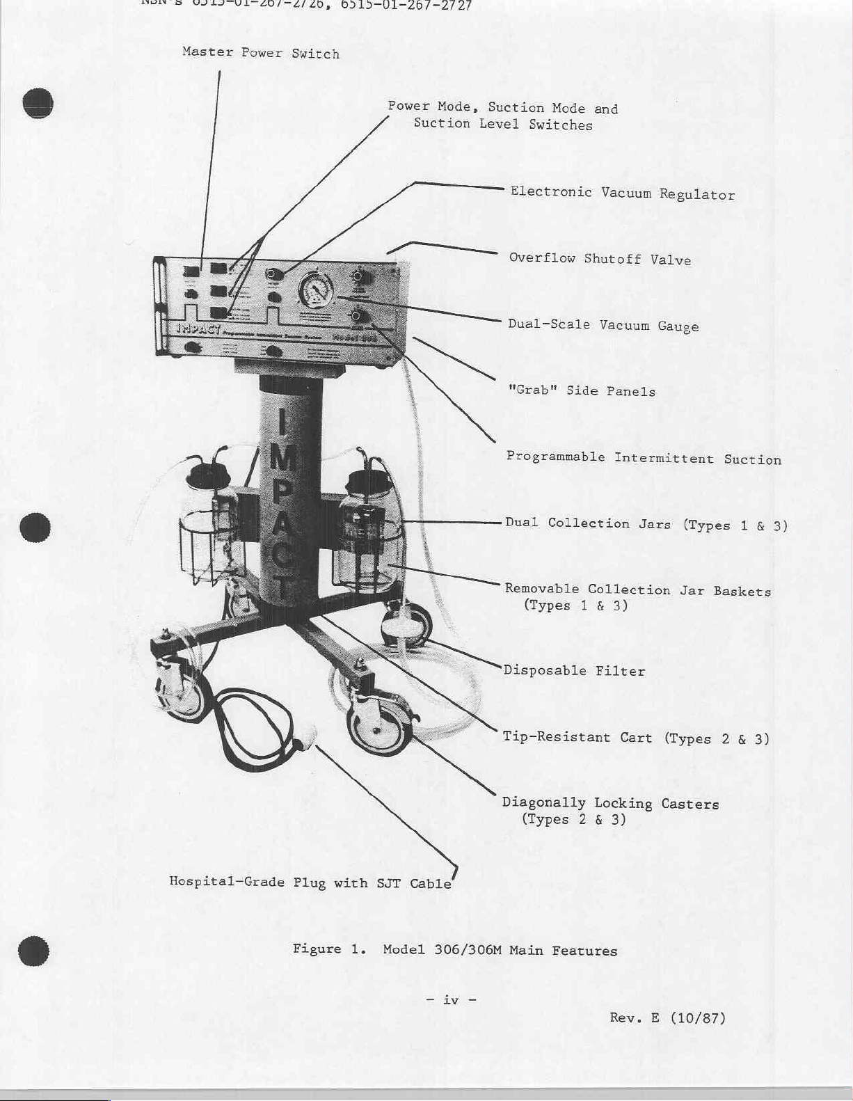
Master
Power
Switch
Power
Suction
Mode,
Suction
Level
Electronic
Overflow
Dual-Seale
"Grab"
Mode
Switches
Side
and
Vacuum
Shutoff
Vacuum
Panels
Regulator
Valve
Gauge
Programmable
Dual
Removable
Disposable
Tip-Resistant
Diagonally
Collection
(Types
Collection
1
&
Filter
Locking
(Types 2 &
Intermittent
Jars
3)
Cart
(Types
Jar
(Types
Casters
3)
Suction
1
&
Baskets
2
&
3)
3)
Hospital-Grade
Plug
with
Figure
1.
SJT
Model
Cable
306/306M
-
iv
—
Main
Features
Rev.
E
(10/87)
Page 6
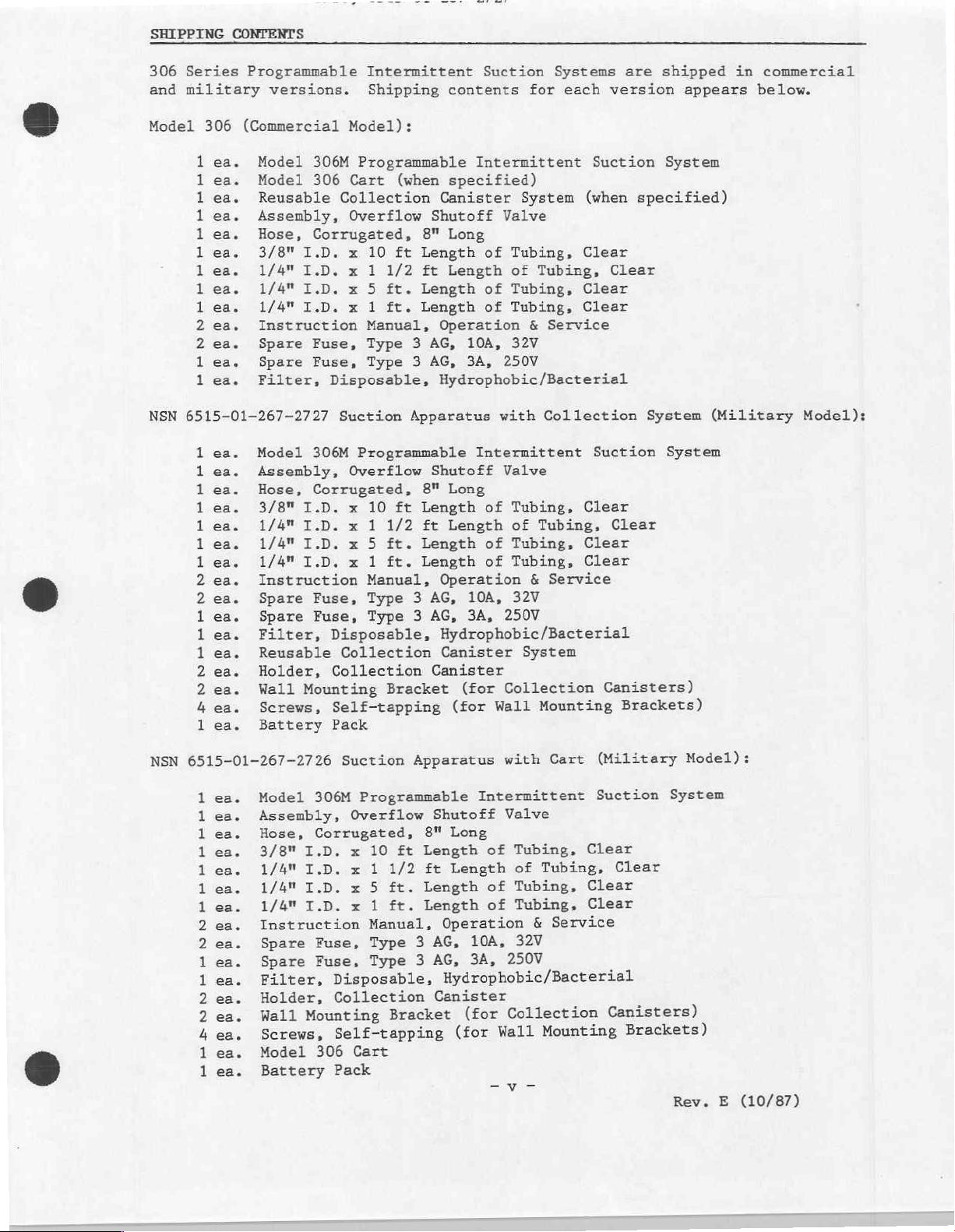
SHIPPING
306
Series
and
military
CONTENTS
Programmable
versions.
Intermittent
Shipping
contents
Suction Systems
for
each
are
version
shipped
appears
in
commercial
below.
Model
NSN
306
ea.
ロビ
ea.
ビビ
ea.
ロロ
ea.
ea.
ビビ
ea.
ea.
ビビ
ea.
ea.
ビビ
らら
ea.
ウゥ
ea.
ea.
ビビ
ea.
6515-01-267-2727
ea.
ea.
ea.
ea.
ea.
ea.
ea.
ea.
ea.
ea.
ea.
ea.
ea.
ea.
ea.
ea.
O
(Commercial
Model
Model
Reusable
Assembly,
Hose,
3/8"
1/4"
1/4"
1/4"
Instruction
Spare
Spare
Filter,
Model
Assembly,
Hose,
3/8"
306M
306
Collection
Corrugated,
I.D. x 10
1.D. x 1
Т.О. х 5
I.D. x 1
Fuse,
Fuse,
Disposable,
Suction
306M
Corrugated,
I.D. x 10
1/4" I.D. x 1
1/4" I.D. x 5
1/4"
I.D. x 1
Instruction
Spare
Spare
Filter,
Reusable
Holder,
Wall
Screws,
Battery
Fuse,
Fuse,
Disposable,
Collection
Collection
Mounting
Self-tapping
Pack
Model):
Programmable
Cart
Overflow
Overflow
(when
Shutoff
8"
ft
Length
1/2
ft
ft.
Length
ft.
Length
Manual,
Type 3 AG,
Type 3 AG,
Apparatus
Programmable
Shutoff
8"
ft
Length
1/2
ft
ft.
Length
ft.
Length
Manual,
Type 3 AG,
Type 3 AG,
Canister
Bracket
Intermittent
Suction
specified)
Canister
Long
Length
Operation
10A,
3A,
Hydrophobic/Bacterial
Long
Length
Operation
10A,
3A,
Hydrophobic/Bacterial
Canister
(for
(for
System
Valve
of
Tubing,
of
Tubing,
of
Tubing,
of
Tubing,
&
Service
32V
250V
with
Collection
Intermittent
Valve
of
Tubing,
of
Tubing,
of
Tubing,
of
Tubing,
&
Service
32V
250V
System
Collection
Wall
Mounting
(when
Clear
Clear
Clear
Suction
Clear
Clear
Clear
System
specified)
Clear
System
System
Clear
Canisters)
Brackets)
(Military
Model):
6515-01-267-2726
NSN
ea.
ロビ
ea.
ビビ
ea.
ea.
ea.
ロビ
ea.
ea.
ロビ
ea.
らら
い
ea.
ea.
ビ
ea.
ビ
らい
ea.
ea.
ea.
よら
ea.
ea.
ロビ
Model
Assembly,
Hose,
3/8"
1/4"
1/4"
1/4"
Instruction
Spare
Spare
Filter,
Holder,
Wall
306M
Corrugated,
I.D. x 10
I.D. x 1
I.D.
I.D.
Fuse,
Fuse,
Mounting
Screws,
Model
Battery
306
Suction
Programmable
Overflow
x
x
Disposable,
Collection
Apparatus
8"
ft
Length
1/2
ft
Length
ft.
5
Length
ft.
1
Manual,
Type 3 AG,
Type
3
Bracket
Self-tapping
Cart
Pack
Cart
with
Intermittent
Shutoff
Long
Length
Operation
AG,
Hydrophobic/Bacterial
Canister
(for
Valve
of
of
of
10A,
3A,
(for
Wall
Tubing,
of
Tubing,
Tubing,
Tubing,
Service
&
32V
250V
Collection
Mounting
(Military
Suction
Clear
Clear
Clear
Clear
Canisters)
Brackets)
Model):
System
Rev. E (10/87)
Page 7
ας,
προς
ROE
ITE"
SI
ROS
SA
PN
ST
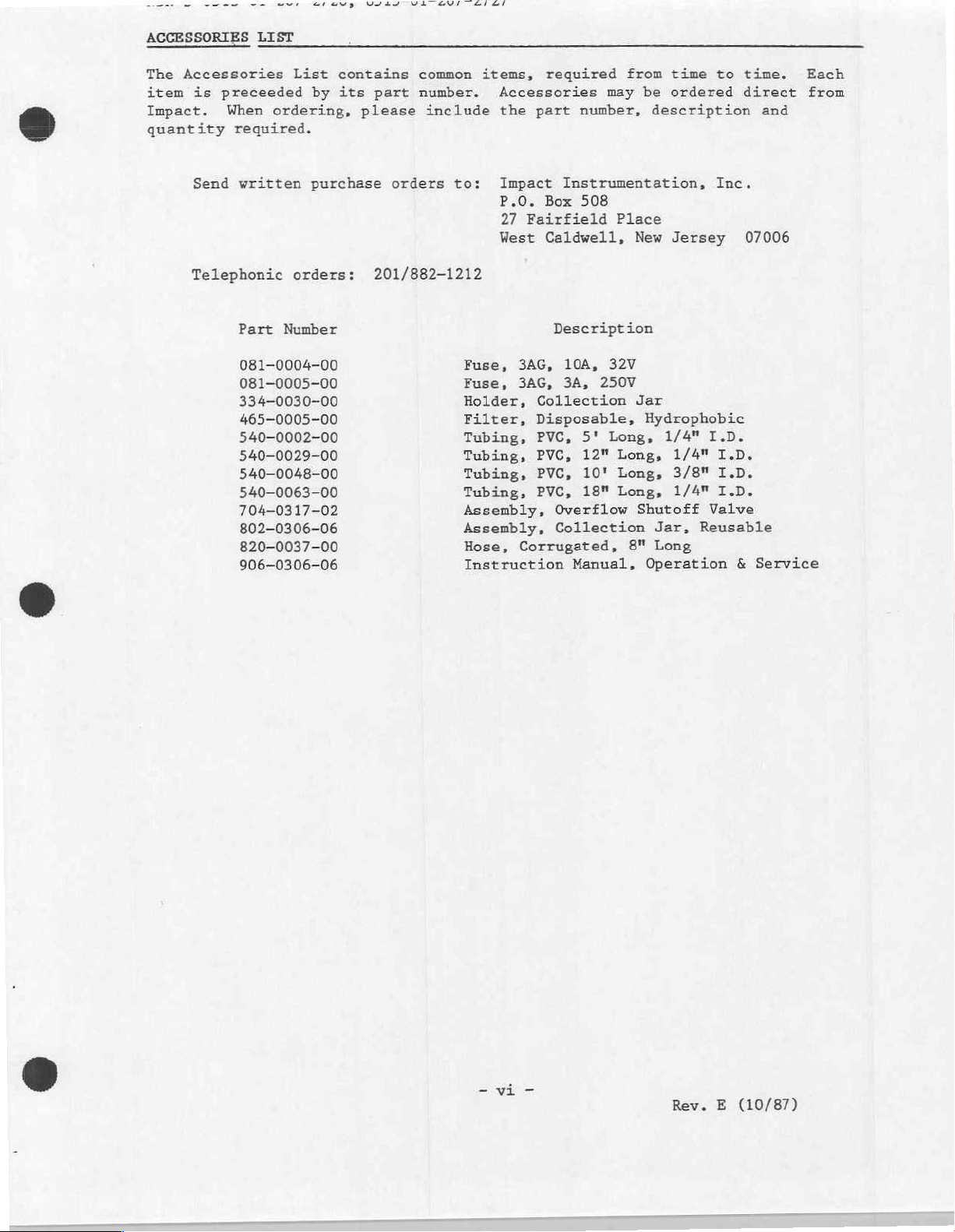
ACCESSORIES
The
Accessories
item
is
preceeded
Impact.
quantity
Send
Telephonic
LIST
List
When
ordering,
required.
written
orders:
Part
Number
081-0004-00
081-0005-00
334-0030-00
465-0005-00
540-0002-00
540-0029-00
540-0048-00
540-0063-00
704-0317-02
802-0306-06
820-0037-00
906-0306-06
contains
by
its
purchase
common
part
number.
please
include
orders
201/882-1212
items,
Accessories
the
to:
Impact
P.O.
27
West
Fuse,
Fuse,
Holder,
Filter,
Tubing,
Tubing,
Tubing,
Tubing,
Assembly,
Assembly,
Hose,
Instruction
required
part
number,
Instrumentation,
Box 508
Fairfield
Caldwell,
Description
3AG,
10A,
3AG,
3A,
Collection
Disposable,
PVC,
5'
PVC,
PVC,
PVC,
12"
10'
18"
Overflow
Collection
Corrugated,
Manual,
from time
may
Place
New
32V
250V
Jar
Long,
Long,
Long,
Long,
Shutoff
8"
to
be
ordered
description
Inc.
Jersey
Hydrophobic
1/4"
I.D.
1/4"
I.D.
3/8"
I.D.
1/4"
I.D.
Valve
Jar,
Reusable
Long
Operation
time.
direct
and
07006
&
Service
Each
from
-vi
-
Rev. E (10/87)
Page 8
E
AN
A
ARE,
LIMITED
COPYRIGHT
Permission
material
program
CALIBRATION
This
program
measurements
and
device
to
warrants
calibration
of
operation.
section
UNPACKING
Check
Examine
no
this
of
the
the
apparent
manual
is
hereby
furnished
other
NOTICE
should
insure
should
a
shorter
check
Recommended
this
contents
instrument
sign
before
RELEASE
granted
under
technical
be
compliance
be
period
should
Manual.
of
of
mechanical
attempting
to
this
contract
training
incorporated
with
made
on a biannual
between
be
made
maintenance
the
shipping
for
any
to
the
Department
programs.
into a regular
operating
preventative
following
case(s)
obvious
damage,
operate
for
use
basis
each
checks
against
signs
read
the
of
Defense
in a military
>
preventative
specifications.
unless
significant
maintenance
cumulative
can
be
found
the
enclosed
of
shipping
the
instructions
instrument.
to
reproduce
service
maintenance
Calibration
inspections.
period
in
the
packing
damage.
contained
all
training
usage
of
300
SERVICE
If
there
within
A
hours
list.
is
LOCATION
The
Model
will
and
vary.
protect
plastic
WARNINGS
This
equipment
Danger
Caution
not
Do
within
Always
External
sources
12VDC
OF
USE
306/306M
When
this
sheet,
REGARDING
is
-
Possible
anesthetics.
Electric
-
servicing
operate
manual.
this
overflow
use
12VDC
when
OPERATION).
2
is a portable
operated
device
etc.).
USE
intended
explosion
shock
to
instrument
this
shutoff
Operation
simultaneous
in a wet
by
covering
for
use
hazard
hazard,
qualified
prior
valve
Operate
—
AC
device,
environment,
it
by
if
not
do
service
to
protect
to
only
power
therefore,
user's
with a protective
qualified
used
remove
in
the
instrument
medical
personnel
reading
is
from
applied
the
pump
diode
(see
mechanism.
its
physical
should
barrier
personnel
presence
only.
instructions
protected
SERVICE
take
of
flammable
covers.
external
section
area
of
precautions
(small
only.
tarp,
Refer
contained
12VDC
EXTERNAL
use
MILITARY
(shipped
VERSIONS
separately)
-
DO
NOT
is
operate suction
installed.
apparatus
until
the
Rev. E (10/87)
battery
pack
Page 9
NSN's
ASSEMBLY,
6515-01-267-2726,
INTERGONNECTIONS
6515-01-267-2727
AND
INITIAL
ADJUSTMENTS
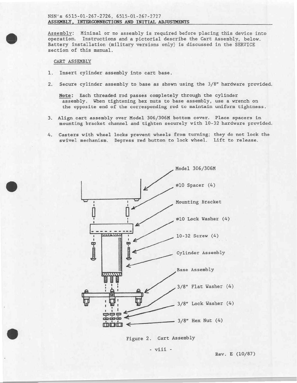
Assembly:
operation.
Battery
section
CART
ASSEMBLY
1.
Insert
2.
Secure
Note:
assembly.
the
3.
Align
mounting
4.
Casters
swivel
Minimal
Instructions
installation
of
this
manual.
cylinder
cylinder
Each
threaded
When
opposite
cart
assembly
bracket
with
mechanism.
wheel
or
no
(military
assembly
assembly
tightening
end
of
channel
assembly
and a pictorial
into
to
rod
passes
the
corresponding
over
Model
and
locks
Depress
prevent
is
versions
cart
base
hex
tighten
red
reguired
describe
only)
base.
as
shown
completely
nuts
to
306/306M
securely
wheels
button
base
rod
bottom
from
to
Model
before
is
discussed
using
through
assembly,
to
lock
placing
the
Cart
the
the
maintain
cover.
with
turning;
10-32
wheel.
306/306M
this
Assembly,
in
the
3/8”
hardware
cylinder
use a wrench
uniform
Place
hardware
they
do
Lift
to
device
below.
SERVICE
provided.
tightness.
spacers
provided.
not
lock
release.
into
on
in
the
AI
ビー
ニー
--
(24
“na
で
ここ
o
a
oe
de
ce
#10
Spacer
Mounting
#10
Lock
10-32
Cylinder
Base
Assembly
3/8"
Flat
3/8"
Lock
3/8"
Hex
(4)
Bracket
Washer
Screw
(4)
Assembly
Washer
Washer
Nut
(4)
(4)
(4)
(4)
Figure
2.
-
Cart
viii
Assembly
-
Rev. E (10/87)
Page 10
NSN's
ASSEMBLY,
6515-01-267-2726,
INTERCONNECTIONS
6515-01-267-2727
AND
INITIAL
ADJUSTMENTS
(cont'd)
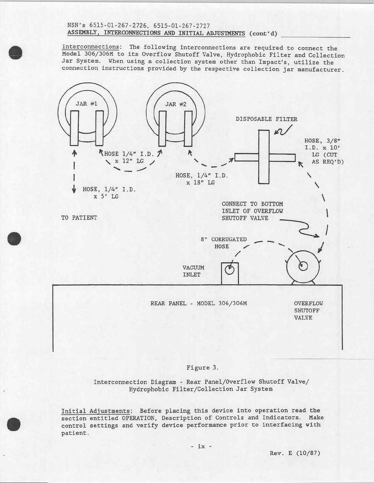
Interconnections:
Model
Jar
connection
306/306M
System.
When
instructions
asi
4
|
|
Ý
TO
PATIENT
KHOSE
HOSE,
x
9°
NE
1/4"
LG
to
1/4"
x
12"
I.D.
The
its
using
E
following
Overflow
a
provided
I.D.
LG
Ea
interconnections
Shutoff
collection
by
ca
À
HOSE,
R
x
the
18"
Valve,
system
respective
N
aio
1/4"
LG
Hydrophobic
other
DISPOSABLE
可
I.D.
CONNECT
INLET
SHUTOFF
are
required
than
Impact's,
collection
TO
BOTTOM
OF
OVERFLOW
VALVE
Filter
FILTER
νι
to
connect
and
utilize
jar
manufacturer.
HOSE,
I.D.
=
R
the
Collection
the
3/8”
x
LG
(CUT
45
REQ'D)
x
X
N
|
η
10!
,
Initial
section
control
patient.
Interconnection
Adjustments:
entitled
settings
OPERATION,
and
REAR
Diagram
Hydrophobic
Before
verify
VACUUM
INLET
PANEL
placing
Description
device
-
MODEL
Figure
-
Rear
Filter/Collection
this
performance
8”
CORRUGATED
HOSE
/
©
306/306M
3.
Panel/Overflow
device
of
Controls
prior
à
и
Jar
into
__
Shutoff
System
operation
and
Indicators.
interfacing
to
_
=
N
OVERFLOW
SHUTOFF
VALVE
Valve/
read
и
the
Make
with
-
ix
-
Rev.
E
(10/87)
Page 11
ーー
-~
veste
va
GUI
TAI
LUS,
OD13-U1-20/—2/2/
SECTION
I.
INTRODUCTION
The
Model
in
art
the
reliable
manual.
this
Electronic
regulators
path
and,
energy
you
micrometer
efficient;
require.
Electronic
times,
selectable
virtually
efficiency.
response.
Emergency
emergency
vacuum
which
mm/hg).
the
battery
levels
can
At
battery
is
restricted
OPERATION
306M
Programmable
portable
service
The
Vacuum
in
several
therefore,
Third,
precision
Intermittent
the
entire
The
ON
Battery
and
transitory
drawn.
provide
200
mm/hg
will
considered
not
emergencies
to
suction
used
when
following
Regulator
ways.
cannot
it
only
the
for
in
144
unit
circuit
- A sealed
With
over
one
cycled
provide
Intermittent
apparatus.
accordance
in
text
-
This
First,
leak,
draws
regulator
your
most
Suction
different
during
immediately
lead-acid
use.
Its
this
of
hour
intermittently
than
more
primary
the
transport
and
Suction
device
with
the
several
differs
regulator
jam
or
proportional
suction
highlights
circuit
the
clog,
current
can
precisely
critical
This
Circuits - These
combinations.
its
time
period
energizes
(GEL
Cell)
operating
in
mind, a high
continuous
time
use
at 5 seconds
power
to
hours
source,
insure
twelve
System
will
instructions
of
from
is
eliminated
stick.
to
select
needs.
circuits
The OFF
thereby
the
battery
varies
capacity
maximum
at
continuous
its
available
represents
provide
key
its
conventional
Second,
the
amount
vacuum
determine
circuit
maximizing
system
for
is
provided
depending
battery
vacuum
ON
and 5 seconds
use.
should
use
power.
the
years
contained
features.
mechanical
from
the
the
regulator
of
levels
ON
shuts
energy
prompt
upon
was
chosen
(550
Because
be
state
of
within
vacuum
vacuum
with
and OFF
dow
for
the
OFF,
this
of
is
OPERATION
Description
Refer
within
to
this
pictorial.
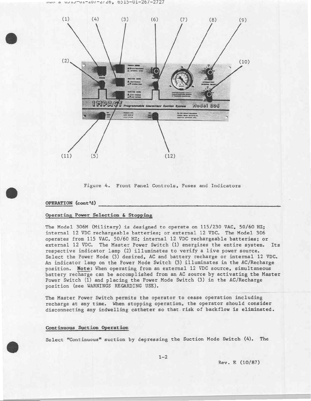
Master
(1)
Master
(2)
Power
(3)
Suction
(4)
Suction
(5)
Vacuum
(6)
of
reference
the
text
Power
Power
Mode
Mode
Level
ON/OFF/ADJ
Controls
parentheses)
(in
Switch
Indicator
Switch
Switch
Switch
Indicators
and
pictorial
Lamp
Switch
following
the
on
correspond
(10)
(11)
(12)
(7)
(8)
(9)
the
to
Vacuum
Vacuum
Time
On
Time
Off
Fuse,
Fuse,
page.
numbers
Regulator
Gauge
Selector
Selector
250V,
3A,
32V,
10A,
Numbers
indicated
Power
Switch
3AG
3AG
contained
Lamp
Switch
in
the
aaah
Rev. E (10/87)
Page 12
мым © VY4JTVLTE0/74/
20,
BDL5-UV1—26/—2/2/
(1)
(11)
(4)
(5)
G)
(6)
(12)
(7)
(8) (9)
OPERATION
Operating
The
Model
internal
operates
external
(cont'd)
Power
306M
12
from
12
respective
Select
An
position.
battery
Power
position
The
recharge
disconnecting
Continuous
the
indicator
Note:
recharge
Switch
(see
Master
at
Figure
VDC
115
VDC.
indicator
Power
lamp
(1)
WARNINGS
Power Switch
any
any
Suction
4.
Selection
(Military)
rechargeable
VAC,
The
lamp
Mode
on
the
When
can
be
and
placing
time.
indwelling
Operation
Front
&
Stopping
is
batteries;
50/60
HZ;
Master
(2)
(3)
desired,
Power Mode
operating
accomplished
the
REGARDING
permits
When
stopping
catheter
Panel
designed
Power
Controls,
internal
Switch
to
or
operate
12
illuminates
AC
and
battery
Switch
from
an
external
from
an
Power Mode Switch
USE).
the
operator
operation,
so
that.
Fuses
external
VDC
(1)
energizes
to
verify a live power
(3)
AC
to
risk
and
Indicators
on
115/230
12
VDC.
rechargeable
the
recharge
illuminates
12
VDC
source,
source
cease
the
by
(3)
in
operation
operator
of
backflow
VAC,
50/60
The
Model
batteries;
entire
source.
or
internal
in
the
simultaneous
activating
the
AC/Recharge
including
should
is
HZ;
306
or
system.
12
VDC.
AC/Recharge
the
Master
consider
eliminated.
Its
Select
"Continuous"
suction
by
depressing
1-2
the
Suction
Mode
Switch
Rev. E (10/87)
(4).
The
Page 13
NSN's
0515-01-207-2726,
6515
OPERATION
indicator
Level
Vacuum),
Vacuum
control
desired
accomplished
evacuate
Remember
(5).
The
(6)
is
read
directly
(cont'd)
lamp
Switch
or
0-550
is
selected.
(6)
clockwise
vacuum
from
that
EVR
"clicked
Intermittent
The
Suction
illuminated
levels
safety
After
preselecting
section,
desired
Mode
for
from
lockout
the
range.
each. A total
tailor"
the
Model
for
(5)
selects
mm/hg
level.
by
blocking
any
collection
the
maximum
indicator
off"
from
Suction
and
intermittent
appearing
allows
the
ON
(9)
Each
of
144
306M
this
switch
two
(High
To
operate
to
its
Preselecting
the
vacuum
lamp
by
turning
the
front
Operation
Suction
at
the
this
desired
and
OFF
circuit
programmable
to
will
operating
Vacuum).
the
"ON"
free
jar
limit
(7)
will
fully
panel
Level
operation.
pump
mode
to
vacuum
(10)
time
is
programmable
your
patient's
not
illuminate
limits
An
indicator
Electronic
position
the
flow
system
Vacuum
Switches
output
operate
and
desired
of
air
when
is
regulated
remain
counterclockwise.
Gauge
To
during
in
level
suction
combinations
needs.
in
for
vacuum;
Vacuum
continue
vacuum
through
preselecting
by
on
until
(8).
(4,
5)
must
prevent
the
as
dangerous
intermittent
Low
described
circuits
in 12
increments
are
available
this
0-200
lamp
illuminates
Regulator
rotating
limit
the
system.
the
the
Suction
the
EVR
Vacuum
be
depressed
Vacuum
in
may
be
mode. . The
mm/hg
(EVR),
it
can
be
Allow
vacuum
Level
Control
readings
high
vacuum
suctioning,
Level
the
set
range
previous
to
of 5 seconds
to
"custom
Suction
(Low
when
to
limit,
Switch
and
the
turn
the
air
Switch
may
a
only.
Low
the
to
be
Electronic
The
EVR
vacuum
Variability
power
when
energy
level
efficient
full
power
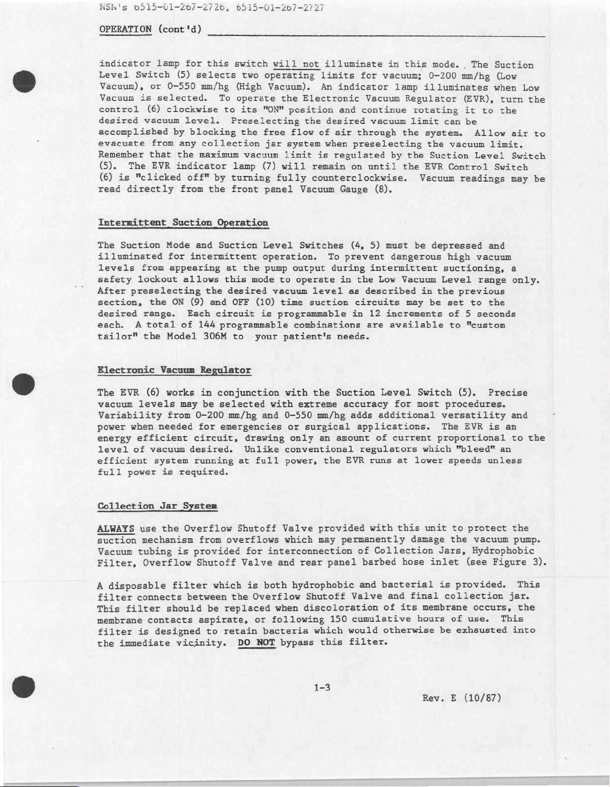
Collection
ALWAYS
suction
Vacuum
Filter,
A
disposable
filter
This
filter
membrane
filter
the
immediate vicinity.
Vacuum
(6)
works
levels
from
needed
efficient
of
vacuum
system
is
Jar
use the
mechanism
tubing
Overflow
connects
should
contacts
designed
is
Regulator
in
may
be
0-200
for
circuit,
desired.
running
required.
System
Overflow
from
is
provided
Shutoff
filter
between
be
aspirate,
to
conjunction
selected
mm/hg
emergencies
drawing
Unlike
at
full
Shutoff
overflows
for
Valve
which
is
the
Overflow
replaced
retain
DO
or
NOT
with
the
with
extreme
and
0-550
or
mm/hg
surgical
only
conventional
power,
Valve
which
interconnection
and
rear
both
hydrophobic
Shutoff
when
discoloration
following
bacteria
which
bypass
Suction
accuracy
adds
an
amount
the
EVR
provided
may
permanently
panel
Valve
150
cumulative
would
this
filter.
Level
for
additional
applications.
of
current
regulators
runs
at
with
this unit
damage
of
Collection
barbed
and
hose
bacterial
and
final
of
its
otherwise
Switch
most
procedures.
versatility
The
proportional
which
lower
speeds
the
Jars,
inlet
is
collection
membrane
hours
be
(5).
EVR
"bleed"
unless
to
protect
vacuum
Hydrophobic
(see
provided.
occurs,
of
use.
exhausted
Precise
and
is an
to
an
the
pump.
Figure
This
jar.
the
This
into
the
3).
1-3
Rev. E (10/87)
Page 14
NSN's
6515-01-20
OPERATION
Operator Performance
Before
operational
1.
Verify
batteries
2.
Verify
operating
3.
Verify
each
4.
Test
low
(cont
placing
operating
continuous
that
of
the
ranges,
'd)
this
checks
and
power
intermittent
the
operating
Electronic
in
Checks
device
to
insure
power
external
operation
modes.
Vacuum
each
into
proper
selections
12
suction
power
of
the
operation,
performance.
at
VDC.
at
both
operates
modes.
Regulator
operating
115
high
by
power
the
operator
or
230
and
low
only
adjusting
modes.
VAC,
ranges,
in
the
can
internal
low
vacuum
perform
in
each
vacuum
in
the
various
rechargeable
of
the
range
high
and
in
1-4
Rev. E (10/87)
Page 15
WOINTS
ODLITYUINL0/—
2/20,
OD19-01-20/—4/427
BATTERY
The
charge
This
procedures.
to-day
understood.
Model
batteries.
subsequent
user
Model
retention
ensures
use,
306M
care
CARE
306/306M
recharge
to
self-discharge
periods
The
receive.
depletion
life
of
disuse
of
Following
and
1.
2.
characteristics,
an
ample
The
battery
therefore,
To
provide
requires
Of
course,
provide
rate
without
these
batteries
reduction
DO
NOT
range
DO
NOT
range
utilizes
amount
pack
it
long
sixteen
the
time
is
optimum
is
extremely
these
of
operate
exceeds
charge
exceeds
sealed
of
should
life
hours
batteries
usually
performance
GEL
particularly
power
in
this
be
and
to
low
replenishment
depends
simple
battery
guidelines
this unit
-60°C
to
life.
this unit
-20°C
to
Cell
batteries
during
device
used with
maximum
fully
are
less.
recharge
rarely
GEL
and
emergencies
is
discretion
performance
life
(approximately
charging
to a great
will
where
60°C
where
50°C
the
(-76°F
the
(-4°F
which offer
during
not
intended
its
discharged
Cell
batteries
expectancy.
1-1/2%
is
possible.
extent
upon
prevent
temperature
to
140°F).
temperature
to
122°F).
long
periods
and
and
capabilities,
fully
this
per
the
premature
excellent
of
transitory
for
routine,
its
design
discharged
much
require
Because
month),
care
they
charge
storage.
the
so
the
little
their
lengthy
day-
Recharging
Ensure
the
(2)
that
Master
illuminates.
position.
ON/OFF/ADJ
unlit.
charging
The
current
replenished
3.
DO
discharged.
4.
For
range
Batteries
the
AC
Power
built-in
Its
Switch
unit
while
NOT
store
long-term
is
10°C
line
cord
Switch
Depress
(1)
the
lamp
"clicked"
is
(6)
in
now
is
automatically
normal
operating
this
unit
Always
storage,
to
30°C (50°F
is
and
ON
Power
will
recharge
a
flows
with
store
the
connected
verify
Mode
illuminate.
and
off
state.
into
power
the
batteries
in a charged
optimum
to
temperature
80°F).
to a 3-wire,
the
that
Switch
(3)
Verify
respective
its
During
batteries
the
requirements
condition.
grounded
Master
the
to
that
normal
keeping
are
Power
and
"AC
Vacuum
the
indicator
operation,
AC
met.
outlet.
Indicator
Recharge"
is
(7)
them
Turn
Lamp
a
Rev. E (10/87)
Page 16

やら
>
VJYLJTV1T60/T4/
40,
0515-01-26/-2
ROUTINE
Cleaning
CARE
Periodically
abrasive
cloth
regular
Collection
their
Impact's
cleansers.
will,
intervals.
respective
reusable
autoclaved.
Maintenance
Routine
and
the
maintenance
prior
following:
1.
Cleaning
2.
Filter
AND
or
when
in
most
jar
systems
to
being
checks - replace
airflow
cumulative
MAINTENANCE
applicable,
DO
NOT
cases,
suffice.
should
instructions.
collection
should
placed
checks - as
performance
use.
be
into
clean
allow
be
cleaned
jar,
performed
service.
described
when
diminishes
the
liquids
Disinfectant
its
cover
on
discolored,
exterior
to
enter
or
disposed
and
this
apparatus
Routine
above.
considerably
case
the
control
spraying
of
hose
connectors
maintenance
contact
or
using
is
in
accordance
at
regular
should
with
following
mild,
system; a damp
recommended
aspirate
may
non-
with
be
intervals
consist
occurs,
150
hours
at
of
of
3.
4.
5.
6.
Overflow
Tubing
Cart
disinfectant
hours
Operational
of
checks
checks
Replace
shutoff
solution
cumulative
checks - as
replace
-
-
verify
worn
casters.
valve
-
when
use.
described
crimped,
smooth
clean
contacted
Dry
turning
in
warm,
with
thoroughly
in
Operator
cracked
of
casters
soapy
aspirate
before
or
water
reassembling.
Performance
tubing
worn
and
or
with a mild
or
following
as
operation
Checks.
required.
of
locks.
150
Rev. E (10/87)
Page 17

NSN's
IN
6515-01-267-2720,
CASE
OF
DIFFICULTY
0515-01-267-2727
Authorization
certified
assume
servicing.
Impact
with
the
factory
attend
Impact
Operator
Common
fail
fittings,
accessory
To
isolate
backwards
the
filter
vacuum
Operator
personnel
any
will,
service
a
factory
Customer
Correctible
problems
to
operate
and
item
through
from
Problems
to
service
will
responsibility
upon
request,
data
and
for
assistance
training
Service
Problems
may
be
properly,
control
or
the
a
problem,
the
to
jar
#1,
the
rear
panel
Requiring
this
instrument
not
be
and/or
provide
schematics.
when
course.
Department.
quickly
verify
settings.
control
check
system,
vacuum
unit
for
i.e.:
from
vacuum
Service
by
other
given,
liability resulting
Such
needed
rectified
the
One
vacuum
the
port
nor
competent
departments
and
Details
by
integrity
can
by
testing
at
vacuum
Overflow
to
does
biomedical
it
may
users.
quickly
for
the
from
the
Overflow
than
Impact
are
is
recommended
be
obtained
Should
of
all
isolate
vacuum
inlet
of
jar
Shutoff
factory-trained
Instrumentation,
from
such
engineering
encouraged
that
by
contacting
the
Model
tube
connections,
problems
at
various
each
item,
#1
to
jar
#2,
Valve
Shutoff
to
and
unauthorized
departments
to
contact
staff
306/306M
to
an
locations.
tracing
vacuum
the
filter,
Valve.
Inc.
members
the
tubing,
from
If
the
tests
required.
Should
representative
Please
wish
located
to
have
include
on
the
described
servicing
or
the
Model
in
Rear
the
your
Panel
above
Impact
and
do
be
Customer
Serial
service
identification
not
resolve
necessary,
Numbers
request.
an
contact
Service
ready
The
label.
operating
your
Department
and
any
Model
306/306M
problem,
nearest
(201)
other
service
Impact
882-1212.
pertinent
Serial
data
Number
is
you
is
Rev. E (10/87)
Page 18

wen's
09212-01-20/-2/26,
6515-01-20
STORAGE
For
The
INFORMATION
prolonged
environment
temperature
be
low.
When
batteries
refresh
LIMITED
Impact
defects
which
will
ninety
does
unauthorized
charge
WARRANTY
Instrumentation,
in
by
be
warranted
(90)
it
apply
range
68°
86°
materials
their
days.
personnel.
storage
should
are
at
Storage Ambient
below
to
to
periods,
be
should
in
extended
recommended
68°F
86°F
(20°
104°F
(30°
be
(20°C)
Inc.
and
workmanship
nature
if
only
This
this
are
consumable
for
warranty
instrument
the
clean,
within
storage,
intervals:
to
30°C)
to
40°C)
warrants
defects
Model
and
out
5°
this
for a period
and
of
is
neither
is
tampered
306/306M
of
direct
to
104°F
it
(-15°
is
recommended
instrument
subjected
manufacturing
assignable
with,
should
sunlight.
to
40°C),
Recharge
18
12
6
to be
of
one
to
environmental
origin
nor
misused
be
stored
Storage
humidity
that
they
Interval
months
months
months
free from
(1)
year.
for a period
transferable,
or
serviced
indoors.
should
receive
all
Batteries,
extremes,
of
nor
by
a
Rev. E (10/87)
Page 19

em:
SPECIFICATIONS
UDIITUI=40/=2/70,
6515-01-207-2727
Vacuum
Free
Temperature
Power:
Controls:
Range:
Continuous:
Low:
High:
Intermittent:
Airflow
External:
Internal:
Operating
Recharge
Master
Power
Suction
Suction
Suction:
On
Interval
Off
Interval
Operating
Power:
Mode:
Mode:
Level:
Range:
Time:
Time:
Select:
Select:
Range:
O - 200
(0 - 8"
0 - 550
(0 - 22"
O -
(0 — 8"
24 - 35
-60°C
115/230
12
1
Hour
16
ON/OFF
AC & Recharge/Internal
mm/Hg,
Hg,
mm/Hg,
200
mm/Hg,
Hg,
Liters
to
60°C
VAC,
VDC
(Rechargeable
at
Hours
(typical)
+/-
+/-
+/-
Hg,
+/-
+/-
+/-
Per
(-76°F
50/60
maximum
25
1"
Hg)
50
2"
Hg)
25
1"
Hg)
Minute
to
HZ;
Batteries)
vacuum
Continuous/Intermittent
High
Vacuum/Low
ON/OFF
5 - 60
5 - 60
/ADJUST
seconds
seconds
Vacuum
in 5 second
in 5 second
mmHg
mmHg
mmig
140°F)
12
VDC
(typical)
12
VDC
(LPM)
increments
increments
Indicators:
Case:
Size:
Weight:
Cart:
Size:
Weight:
Specifications
Instrumentation,
prior
notification.
contained
reserves
Inc.
herein
Master
AC & Recharge
Intermittent
Low
Vacuum
Suction
Vacuum
Aluminum,
46cm W x
(18" W x
11
KG
46cm
W x
(18"
W x
11
Кб
represent
right
the
Power
Gauge - Dual
(25
(25
to
Lamp
Suction
Level
"ON"
Lamp
Epoxy
18cm
7"
H x
lbs.)
46cm
18" D x
lbs.)
typical
change
Lamp
Lamp
Paint
H x
D x
device
Scale,
25cm
10"
75cm
30"
these
Mode
D)
Lamp
Metric/English
Combination
D
H
H)
performance.
specifications
Impact
without
Rev. E (10/87)
Page 20

NSN's
0515-Ui-20/-2/20,
SECTION
II.
INTRODUCTION
The
information
and
certified
of
this
product.
resulting
injuries
Impact
at
no
or
Instrumentation
schooling
therefrom
in
travel,
The
Impact
towards
rectifying
addressed
Place,
West
CAUTIONARY
External,
12VDC
SERVICE
personnel
from
unauthorized
damages
shall
meal
service
to
the
Caldwell,
NOTES
Operation
contained
The
manufacturer
incurred
charge
be
borne
and
time
facility
any
Service
New
herein
or
military
servicing
will
provide
to
users;
by
costs
encourages
service
Manager,
Jersey
is
does
therefrom.
however,
the
user.
charged
related
Impact
07006,
intended
personnel
not
authorize
nor
will
service
training
travel
Training
to
the
dialogue
matter.
Instrumentation,
201/882-1212.
only
trained
it
and
at
user
from
All
for use
in
or
be
held
at
meal
the
user's
at
prevailing
user
service
by
factory-trained,
the
care
assume
liable
the
manufacturing
costs
site
service
requests
Inc.,
and
servicing
any
obligations
for
any
resulting
will
rates.
personnel
may
27
Fairfield
site
result
be
Warning:
employed,
potentially
operation
Internal
Military
cartons.
installed.
HELPFUL
Before
moments
Check
no
crimps
Insure
valves
Refer
troubleshooting.
Always
If
insure
from
Rechargeable
versions
Prior
HINTS
attempting
to
integrity
the
or
that
not
do
the
to
insure
voltages.
simultaneous
that
high
currents.
an
external
of
to
placing
Do
not
to
insure
all
that
cuts
in
collection
stick.
enclosed
Isolate
integrity
the
AC
recharging
the
external
This
12VDC
Battery
this
product
this
operate
this
repair/calibrate
the
problem
vacuum
all
of
it.
jars
schematics
problem
the
of
12VDC
warning
source.
are
device
unit
is
hoses
seal
and
circuit
and
source
does
shipped
into
until
this
not
and
accessory
battery
instrument,
properly.
assembly
functional
a
to
ground
external
is
not
apply
with
operation,
tubing.
Insure
drawings
and
12VDC
diode
batteries
pack
protected
for
the
is
please
related.
Verify
that
when
segment
correct
the
operation
against
independent
in
separate
battery
installed.
pack must
take a few
the
that
overflow
electrically
the
of
power
is
tubing
shut-off
circuitry.
supply
be
has
Always
circuitry.
safeguard
Keep
your
jewelry
personal
and
well
liquids
being
from
JET
troubleshooting
when
vicinity
the
electronic
of
active
circuitry.
Rev. E (10/87)
Page 21

RN
V
SE
DISASSEMBLY
Required
Screwdriver,
Screwdriver,
Allen
3/8"
Pliers,
Wrench,
General
For
the
Panel
When
Top
rear
Insert
wrench,
socket
medium
Open-end,
Access
calibration
top
cover
should
disassembling,
Cover - The
lip,
and
/REASSEMBLY
Tools
slotted,
phillips
and
also
and
tighten
1/16"
drive
size
and
of
this
Top
three
medium
head,
handle
3/8"
many
device.
be
disengaged.
snap
Cover
(3)
each
screw
size
medium
servicing
open
is
secured
along
size
procedures,
For
greater
applicable
by
the
top
when
reassembling.
accessibility,
cable
six
edge.
(6)
the
technician
clamps
screws;
however,
before
three
need
only
the
removing
located
remove
Front
wires.
along
the
Front
Panel
Panel - The
from
disconnect
disengage
are
disconnected,
To
disengage
Front
respective
rear
of
vacuum
at
each
front
underneath).
positioned
the
Chassis
assemblies
To
reassemble,
with
the
seven
vacuum
jacks
drawings).
Sub-Assembly
Printed
assembly.
Board
panel.
panel
connection
general
gauge
(observe
Circuit
jacks.
green
A
one
by
access.
the
Model
the
Front
Panel
ON
Front
Panel,
Printed
gauge.
corner
The
Front
flat
(on
by
the
Wire
may
be
serviced
carefully
screws.
and
connect
pin
polarity
Access
Board
Disconnect
Remove
wire
these
of
the
with
following
306/306M
Panel
to
perform
and
OFF
disconnect
Circuit
The
and
three
Panel
its
facing
Harness
reposition
Connect
P1
The
-
ribbon
four
the
connected
four
Front
Panel
steps
case.
are
contained
Time
Board
Front
(3)
can
surface).
service
or
removed
the
and
P2
-
see
Board
PC
cables
screws
to
screws.
whenever
are
to be
Additional
later
calibrations.
circuits
ribbon
sockets.
Panel
across
now
be
cannot
Disconnect
is
secured
the
pulled
The
loop
with
the
the
Front
two
pieces
to
their
Schematics
located
is
and
P2
Pi,
secure
terminal
purpose
the
a
which
ring
Its
taken
steps
in
only
this
When
be
cables
P1
by
front
away
Front
and
ribbon
Front
Panel
of
vacuum
respective
and
Printed
on
from
P3
the
is
is
Front
to
section.
ribbon
adjusted.
and
vacuum
seven
bottom
from
Panel
Panel
in
place
Printed
the
their
PC
secured
maintain
to
Panel
to
disengage
"electrically"
Do
cables
P2
from
tubing
(7)
screws;
edge
(access
the
Chassis
is
still
cable
left,
P3.
in
and
tubing
Circuit
sub-side,
this
secure
to
Circuit
Board
respective
to
to
the
Board
a
disengaged
is
the
Not
P1
and
their
attached
and
captive
А11
position.
rear
the
sub-side
ground
Front
P2
to
located
from
to
sub-
tightly
of
Board
Assembly
sub-
.
PC
sub-side
for
8-1
Rev. E (10/87)
Page 22

NON'S
O21)-U1-40/-—4/20,
0515-01-267-
DISASSEMBLY
To
reassemble,
with
screws.
screw.
polarity
Battery
main
Chassis.
The
other
lower
keps
the
terminals
nuts.
brackets
open-end
and
B2
are
Reassemble
series
with
terminal
Schematic
pack
Motor
motor
to
in
the
and
Chassis
and
respective
other.
temperature
the
black
chassis
inlet.
six
(6)
The
keps
respective
/REASSEMBLY
position
Make
Connect
-
see
Schematics
Pl,
Pack - The
One
bracket
To
remove
mentioned
wrench.
"fast-on"
the
battery
the
small
and the red
drawing
place
with both
Pump
Assembly - The
with
pump
shafts
shaft
Stacking
extremes.
and
red
ground,
the
motor
nuts
keps
nuts.
(cont'd)
the
PC
sure
the
green
P2
and
P3
to
and
Battery
bracket
snugs
of
each
the
battery.
the
Battery
Pack
snugs
battery
earlier.
Disconnect
connected
pack
orange
wire
to
the
by
jumper,
the
Sheet 1 of 3 for
brackets
Motor
six
(6),
#10-32
together.
via
two
(2),
set
prevents
wires
red
and
or
individually
the
To
disassemble
exiting
wire
pump
coupling
to
can
Board
wire
their
PC
Board
is
secured
the
Each
Pack,
Use the
"fast-on"
in
series
first
remaining
Battery
and
keps
Each
screws
the
TB2-6.
now
be
by
over
four
is
secured
respective
Assembly
battery
pack
to
bracket
remove
3/8"
with a small
connecting
the
black
tighten
and
Pump
threaded
beneath
drawings).
by
two
brackets
pack
to
the
rear
is
the
socket
connected
the
wire
positive
Pack
wiring).
the
four
Assembly
PC
secured
female
Board
the
panel
four
with
red and
orange
batteries,
to
the
terminal
(4)
is
nuts. A flexible coupling
side
of
the
coupling
(1/16"
from
the
Motor
motor.
Disconnect
disengaged
removing
hex)
loosening
and
The
black
as
the
stacked
stacked
due
Pump
wire
vacuum
one
unit
studs
the
lower
jacks
(observe
connected
left,
(4)
drive
sub-side
and
straddles
with
two
keps nuts
handle
black
jumper.
Bl
and
remaining
(refer
Secure
keps
the
nuts.
mechanically
is
secured
one
on
to
vibration
Assembly,
is
connected
tubing
set
by
removing
screws
from pump
and
secure
left-hand
pin
to
the
panel.
the
(2)
#10-32
securing
or
wires.
B2,
negative
to
battery
secured
joins
to
its
top
of
or
disconnect
to
the
and
3/8"
B1
in
the
the
Reassemble
allow
shafts
coupling
for
Position
shaft.
screws
Heat
secured
to
keps
Do
in
Sink
by
TB2-6,
nuts
Reassemble
reattaching
then
Heat
Sink
standoffs.
removing
and
(TB1
2
as
inline
motor
the
each
#1
two
the
can
by
#2
Two
these
TB2)
follows.
to
"float" freely
alignment.
shaft
same
half
-
#10
white
be
with
of
Heat
keps
wire
removed
(flat
Sink
securely
violet,
the
Sink
Heat
-
slotted
screws,
other
and
Mount
and
Tighten
edge)
pump
shaft.
coupling.
#1 is
nuts.
To
going
using
mounting
white
is
#2
screws
wires
six
locations
loosely
on
shafts.
keps nuts
and
tighten
Insert
Connect
mounted
disassemble,
TB2-5
to
3/8"
the
Sink
Heat
and
indirectly
must
as
Heat
be
secure
secure
Carefully
respective
and
red
and
the
to
the
and
socket
to
#1
blue
wires.
Chassis
Sink
disconnected
noted.
motor
without
tighten
black
right,
sub-side
disconnect
wire
blue
drive
with
right,
the
mounted
these
to
#2
at
Disconnect
and
pump
to
position
motor
disturbing
coupling
stacked
wires.
panel.
violet
the
going
to
handle.
sub-side
through
standoffs.
terminal
yellow
the
Rev. E (10/87)
Chassis,
and
alignment.
set
screw
(second)
It is
wire
TB2-4.
panel
two
boards
wire
pump
to
set
going
The
and
Before
and
1
with
Page 23

NSW's
6515-01-26
2726,
6515-01-267-2727
DISASSEMBLY/REASSEMBLY
the
male
Disconnect
the
orange
going
D1-4
that
Disconnect
To
insuring
Connect
to
"fast-on"
two
black
reassemble,
that
vacuum
respective
Transformer
nuts.
on"
wire
wrench.
Disconnect
connections),
at
TB2-1.*
*Model
connected
To
reassemble,
noted.
in-line
the
wire
TB2-3.
vacuum
locations.
306M
"fast-on"
two
going
The
terminals.
wires
tubing
position
both
tubing
-
The
the
one
The
only.
to
the
secure
(cont'd)
terminal
yellow
wires going
to
TB2-2,
two
green wires
Remove
are
ring
entering
Heat
ground
to
solenoid
wires
Transformer
two
green wires
gray
wire
Transformer
Disconnect
transformer
Transformer
the
terminal
Sink
(black)
is
at
can
positioned
to
blue
from
the two
connected
solenoid.
#2
over
are
and
reattach
secured
(Transformer
TB1-3
now
the
orange
primary
to
Chassis
TB1-1,
wire
going
Tl
(secondary)
screws,
its
tightened
to
the
(Model
be
removed
and
("fast-on"
and
along
the
side
red
to
previously,
to
ground
respective
beneath
the
remaining
Chassis
secondary)
306
only)
using
violet
connections).
reconnect
of
wire
TB2-4,
can
be
through
standoffs
by
two
and
the
wires
wires
Transformer
going
and
to
the
removed
mentioned.
one
and
the
front
wires
(2)
at
the
3/8"
as
to
#10-32
D1-4
other
open-end
previously
(T1).
TB1-2,
red
wire
at
Note
screw.
secure,
screw.
their
keps
("£ast-
gray
the
Front
together.
left,
of
the
TB1-4,
along
terminal)
3,
To
Panel/Wire
Follow
disconnect
the
Printed
Printed
gray
side
to
orange
at
reassemble,
instructions.
Rear
cover
three
vacuum
Panel
Panel
must
located
tubing
the
to
Disconnect
TB1-4。
white
("fast-on")
Model
wires
yellow
Select
("fast-on"
T1
indicated.
vacuum
Circuit
Circuit
at
TB1-3,
of
Tl,
ground
TB2-2.
connect
Assembly
first
on
connected
sub-side
following
the
to
and
306M
follows:
as
from
Switch
tubing.
Harness - These
the
General
the
green
ground
Board.
Board.
red
yellow
on
The
The
at
TB1-2,
at
in-line
Heat Sink
Front
wires
order
In
-
removed.
be
the
panel
underside
Rear
to
panels.
line
AC
in-line
(S8)
Disconnect
Disconnect
black
wires
TB2-1.
at
TB2-3.
only:
its
connections).
Rear
Secure
the
Remount
combined
Access
wire
Disconnect
following
yellow
#2,
Panel
listed
disengage
to
bottom
The
Panel.
Panel
The
cord
the
Chassis
at
"fast-on"
follows:
as
To
Panel
bottom
the
assemblies
instructions
secured
the
wires
at
"fast-on"
brown
at
with Wire
above
and
cover
three
and
Remove
can
wires:
wires
red
External
the
ground,
connector.
gray
reassemble,
each
to
cover.
to
ribbon
are
in-line
to
Rear
TB2-5,
Harness
as
directed
Rear
the
is
along
four
be
now
green
from
Power
at
reconnect
sub-side
should
first.
the
bottom
cables
also
"fast-on"
Panel,
blue
can
Panel
secured
the
screws
(4)
positioned
Chassis
to
F3
Jack
yellow
Disconnect
TB1-3,
panel.
be
removed
Starting
left-hand
Pl,
P2
disconnected:
positioned
black
at
TB2-4,
now
be
removed.
in
General
Assembly,
six
with
edge.
rear
holding
face
ground,
"+"
B2
at
(34)
TB1-1
at
AC
the
violet
all
and
wires
Connect
from
the
corner
and
P3
black
(via
ring
red
at
Access
bottom
the
screws,
(6)
Disconnect
the
down.
black
terminal
and
Voltage
orange
as
the
from
at
TB2-
Rear
to
at
8-3
Rev. E (10/87)
Page 24

NON
pb
9242791-20/-4/20,
OD15—U1—20/—2/2/
CALIBRATION
Required
А.
B.
с.
Procedures
A.
B.
PROCEDURE
Equipment
Oscilloscope,
sweep,
Small,
storage
slotted
Stopwatch,
Maximum
1.
2.
3.
4.
Low
Set
controls
have
Select
Turn
Occlude
reading
5.
This
applied
Intermittent
DC,
capability
screwdriver.
minimum
Vacuum
been
fully
CONTINUOUS
Vacuum
the
on
regulator
Rear
the
reading
to
the
ON/OFF Timing
Triggered,
0.1
second
Level Limit
for
either
charged
and
Panel
Front
may
be
verified
vacuum
with a minimum
desirable.
resolution.
AC
or
DC
if
calibrating
LOW
VACUUM
ON
and
fully
Vacuum
Panel
Inlet
vacuum
using a calibrated
inlet.
Circuits
5
operation
operation.
clockwise.
and
adjust
gauge.
second
(insure
from
horizontal
battery
R2
for a 200
vacuum
that
power).
batteries
mm/Hg
gauge
Note:
An
described
Model
the
NOTE:
simplicity
the
306/306M
pump
Steps
oscilloscope
circuit.
oscilloscope
below.
However,
using a stopwatch.
turning
1.
2.
3.
4,
5.
on
Set
controls
have
Select
Set
ON/OFF
Turn
Trigger
and
Close
oscilloscope.
6.
Trigger
adjust
Adjustments
of a storage
5.
and
and
convenience,
triggering
may
the
and
off
been
fully
INTERMITTENT
times
Vacuum
adjust
6.
regulator
the
oscilloscope
R36
verification
the
oscilloscope
R35
to
above
be
used
to
technician
In
as
the
reference
for
either
charged
and
for 5 seconds
to
set the
can
Adjustments
set
the
should
type
may
the
slope
be
oscilloscope
be
positive
set
calibrate
may
such
cases,
AC
or
if
calibrating
LOW
VACUUM
ON
and
fully
sweep
ON
be
made
should
to
begin
OFF
Time
to
within
monitored
voltage
for
the
the
ON/OFF
find
it
easier
the
technician
for
keying
DC
operation
from
operation.
ON, 5 seconds
clockwise.
to
begin
Time
using a storage
when
circuit
+/-
will
at
ON
when
circuit
be
to
the
for a 5
0.5
simplify
various
motor
circuit,
seconds.
Timing
the
stopwatch.
(insure
battery
OFF.
the
for a 5
within
motor
measurement.
points.
input
then
Circuits
to
calibrate
can
that
power).
motor turns
second
type
+/-
0.5
turns
second
Again,
For
should
reset
utilize
batteries
sweep.
seconds.
off
and
sweep.
the use
be
used
for
OFF
ui
as
the
on
and
«di
Rev. E (10/87)
Page 25

NSN!s
6515-01-267-2726。
6515-01-267-2727
CIRCUIT
Refer
AC
Ti,
simultaneous
$2)
Charging
exists,
DESCRIPTIONS
to
the
_to
DC
Rectifier,
Dl-4,
indicates
current
but
replenish.
activated,
battery
illumination
Master
battery
prevents
the
306M)
recharge.
Power
power
simultaneous
battery
permits
220-240VAC.
whenever
external
recharge
the
12VDC
and
Components
Chassis
and
Rear
mounted,
Panels.
enclosed
and
Cl
operation
the
will
Switch
prevents
of
switch,
or
pack
user
J4
Master
operation
D1-6,
Power
represent
presence
will
taper
S1A
Components
L2
during
rectified
from
selection
(Model
from
any
C1
and
while
schematic
and
a
full
and
recharging
of
be
higher,
downward
and S1B
operation
battery
illuminates
AC.
operation
high
current
306M)
Power
enables
switch
other
from
AC
R1
are
the
other
diagrams.
Charging
wave
battery
initially,
towards
acts
from
D5
and
in
Note
from
of
the
is
power
power
mounted
components
Circuits
bridge
capability.
charging
the
as a Master
internal
D6
are
operation.
both
internal
that
S2A and
internal
discharges
input
AC
operation
activated.
source.
when
external
to
Heat Sink
—
Components
rectifier
current
when a discharged
50 - 75
Power
or
external
blocking
Lamp
and
S2B
and
external
in
excess
source;
from
Blocking
This
allows
circuit
Lamp
L2
which
ma
level
control,
power
diodes
L1,
associated
external
reciprocate
of
either 117VAC
an
external
diodes
simultaneous
12VDC
#2
(Flat
of
this
section
P4,
(which
is
battery
as
sources
which
power.
10A.
is
connected.
Heat
appear
S1A,
which
is
limited
the
which
prevent
with
power
which
S8
12VDC
D5
Sink),
F1,
S2A,
enables
part
of
by
state
batteries
unless
and
false
the
modes
F3
protects
(Model
(nominal)
source
and
D7
block
battery
T1
at
the
Front
Rl.
via
or
is
Suction
S4A,
to a Rotary
relative
acts
S5A,
as
Level
Q1-3
Vane
to
the
an
electronic
and
and
motor
switch/potentiometer
amplifier,
increases
generate
depending
can
be
However,
limited
of
200
direct
reciprocating
following
S5A
are
on
Heat
Intermittent
order
In
patient,
intermittent
part
is
illuminates
Front
the
higher
upon
applied
if
by
mm/Hg
input
Front
Sink
to
switches
of
Panel
Q1-Q3.
paralleled
vacuum
the
to
S4A
is
the
setting
when
to
the
switches
sections.
Panel
#1,
Operation
prevent
operation
illuminates
S5
when
mounted.
Motor
M1
comprise
vacuum
speed
vacuum
which
Increasing
and
position
the
base
opened,
of
properly
base
whose
Lamp
mounted,
and
M1
dangerously
S4B
and
can
Vacuum
Low
Speed
pump.
driving
regulator.
provides
the
outputs
airflow
of
of Ql
the
R2
and can
calibrated.
of
01.
alternate
L3
illuminates
R2
is
Chassis
—
Components
S5B
must
exist
the
in
is
Control
this
section.
The
vacuum
it;
base
positive
of
Q2
levels.
S4A.
When
which
maximum
only
Note
is
located
mounted.
vacuum
high
both
only
Intermittent
selected.
Circuits — Components
Motor
and
hence,
Component
drive
potential
and
Q3
causing
Two
S4A
is
generates
potential
Ml
is
airflow generated
the
Motor
S3/R3
to a two-stage
at
the
M1
vacuum
ranges
closed,
maximum
available
provide a maximum
Switch
that
functions
whenever
S4B, S5B,
be
the
in
S4A
on
the
levels
closed.
"LOW
Mode
components
All
S5A,
when
and S4B
will
S3 is
Printed
L4
and
from
This
VACUUM"
and
and S5A
be
L5
L5
F2,
L3,
mechanically
by
Speed
Control
is a rotary
emitter
base
of
to
turn
faster
are
full
power
vacuum
closed,
described
to
pump
levels.
the
output
provides
and
closed.
Circuit
comprise
being
presented
guarantees
mode.
which
in
Lamp
is
this
S3/R3,
coupled
this
circuit
follower
Ql
possible,
potential
base
of
S5B
are
in
the
S3/R3,
Board,
this
circuit.
that
L4
part
section
R2,
pump
and
Ol is
level
a
S4A and
01-3
the
to
which
s4
of
are
is
10-1
Rev. E (10/87)
Page 26

MON > ご
フュ
フー
リュ ォ ーZO7 一 Z/
ZD 。 B515—-U1-26/
CIRCUIT
NOTE:
Intermittent
5-Volt
power
acts
voltage
4.8V
turn-on
ON
Clock
generator
provide
NOR,
DESCRIPTIONS
The
Power
supply
as a current
at
maximum
(initial
cycle.
Oscillator
an
dual
Board.
555
monostables
brings
HIGH
capacitor
of
the
logic
time,
internal
to
return
sometimes
unit may
following
remaining
Operation.
Supply - Components
for
the
limiter
filtering
low
of
vacuum
surge),
Ali
components
-
consisting
initiating
in-line
Timer
for
trigger
level
rises
the
comparator
flip-flop,
to a LOW
20%
cycle
two
package.
‘ration - These
the OFF
input
(Vcc).
exponentially
causing
logic
triggered
once
before
sections
(cont'd)
descriptions
Intermittent
to
the
transient
levels
and
rises
are
The
Clock
of
IC1
pins
input
Time
to
All
and
(pin
Simultaneously,
input
the
level
when
intermittent
stabilizing
describe
apply
R4,
timing
regulator
power
to
IC4
surges.
(motor
to
about
mounted
to
Oscillator
8-13,
the
components
OFF
R5,
time
integrated
ON
Time
2)
below
through
1/3
the
(pins 6 and
capacitor
(ground).
to
each
timing
circuitry
and
C2
and
switching
input
The
off),
approximately
4.5V
the
Printed
is a 50
R6
and
monostable.
are
mounted
circuits
circuits.
Vec,
the
voltage
timing
7)
reaches
to
discharge
The
timer,
operation
its
correct
circuit.
in
use
only
during
provide a regulated
circuitry.
while
regulator
for the
HZ,
the
resistor,
C2
provides
output
3V
duration
Circuit
self-starting,
C3.
Its
purpose
IC1
is a quad-2
to
the
are
used
When a negative
output
across
2/3
in
is
(pin
the
and
Vec,
to
ground
this
application
initiated,
time
period.
during
Board.
Printed
as
functional
3)
timing
after a period
resetting
low
Resistor
output
is
typically
motor
of
the
square
is
to
Circuit
impulse
goes
and the
thus,
The
voltage
R4
motor
wave
input
to
a
the
output
is
the
Off
Time
that
consists
1-3
comprise
inversion
held
output
mistriggering
determine
and
R37
(.975
=
Time
On
determines
C7,
C5,
monostable
Time
3
pin
Printed
are
Monostable
the
On
of
of
LOW
when
into
the
are
.125)
+
Monostable
for
C8,
and
Monostable.
the
and
Relay System
Time
On
the
function,
"dumps"
Time
Monostable
IC1
pins
a
NOR
gate
the
Clock
the
On
positive
of
the
time
periods
used
to
RC.
-
long
how
R23-34,
R8,
corresponding
its
The
Relay
Circuit
The
-
Monostable
the
-
The
1-3,
of
Oscillator
Time
and
negative
monostable
adjust
components
All
On
The
the
R36
Time
On
System
Board
Relay
with
vacuum
purpose
output
IC2,
C4,
which
pin 3 is
when
Monostable
impulses,
and
for
which
the
delay
Monostable
Time
Time
Off
R38
and
components
output
direct
both
mounted.
System
provides
Motor
the
collection
of
this
remains
C6,
C9,
the
is
HIGH.
are
applied
the
multiplier
mounted
are
Monostable
comprise
triggers
and
Speed
system
circuit
LOW.
R7,
its
On
biased
Off
controls
act
through
two
Control
is
The
R11-22,
output.
Time
Monostable
R7
and
at
to
IC2 pin
Time
Monostable
in
the
the
to
remains
circuit.
this
the
in
Off
the
101
functions;
atmospheric
to
to
control
Off
Time
R35 and
This
C4
shape
Vcc
to
time
Printed
relay
the
LOW.
same
Monostable
Time
pin
first,
circuit,
the
Monostable
R37.
output
is
is
LOW.
the NOR
prevent
2.
C6
and
is
HIGH.
period
Essentially,
manner
4
and
equation:
Circuit
system
Components
as
components
All
interfaces
it
as
pressure
time
period
IC1
an
Pin 3 is
gate
R11-22
C9,
Board.
and
this
the
via
secondary
a
during
pins
R35
T
IC3,
Off
1C1
10-2
Rev. E (10/87)
Page 27

WeN'S
DI
LITUI=40/=4/40,
©65215-01-26/
CIRCUIT
off
cycles.
During
R2,
combination
not
Off
4
solenoid
On
R3
energized
cycles,
goes
HIGH
series
collection
next
On
circuit
Circuit
Waveforms
schematic
what
constitutes
performance
DESCRIPTIONS
The
Relay
Time
cycles,
combination.
during
during
Kl
is
and
turns
to a normally
system
cycle.
and
Board;
and
drawing.
Switch
solenoid.
Q5
voltage
an
over a broad
(cont'd)
System
relay
each
On
the
On
normally
Q4
on.
open
is
"dumped"
S3
must
Components
and
the
solenoid
measurements
In
most
acceptable
range
consists
K1
is
The
motor
cycle
cycle,
open
unless
and
When
state.
to
atmospheric
be
closed
K1,
kKeENOTERRE
cases,
voltage
of
conditions.
of
K1,
closed
thus
stops
K2
When
to
have
considerable
and
speed
changed
allowing
Ml.
closes,
the
to
K2,
Q4
Heat Sink
been
value
K2,
provides
is
then fixed
by
the
Relay
Q5
turns
solenoid
pressure
operate
amd
R9
#2.
noted
leeway
in
order
Q4, Q5,
base bias
the
operator.
vacuum
K2
on
opens,
and
the
Motor
are
mounted
at
various
has
to
R9,
and
by
the
to
is
energized
and
energizes
the
remains
Speed
locations
been
maintain
the
to
R2,
Relay
exist.
vacuum
so
to
the
given
device
solenoid.
Ql
from
R3
K2
During
as
IC1
the
until
Control
Printed
on
as
the
is
pin
the
each
to
10-3
Rev.
E
(10/87)
Page 28

や
らい ら ウン
フォ ュ ン ー ロ
ュー と ロワ ィ ー ン 7
と O 。 DDLD—U1—20/—2/2/
PREVENTATTVE
Preventative
to
insure
visual
and
Preventative
Visual
leakage
turned
Checks:
1.
and
2.
off.
3.
Inspection
Check
Check
discolored.
4,
Check
fitting
lids.
MATNTENANCE
maintenance
proper
performance
device
maintenance
If
monthly
If
monthly
Visual
general
the
the
collection
Replace
TNSPECTTONS
inspections
performance.
checks,
inspections
usage
usage
checks
of
tubing,
wear.
vacuum
disposable
jars
as
and
is
less
is
greater
should
fittings
They
should
gauge
for a "zero
Hydrophobic
for
required.
should
These
cleaning
(PMI)
than
than
include,
be
chips
be
inspections
when
should
50
hours ~ PMI
100
but not
and
collection
replaced
area"
Filter
or
cracks
incorporated
should
warranted.
be
made
bimonthly.
hours - PMI
be
jars
as
necessary.
reading
for
discoloration.
in
bottle,
on a routine
consist
as
follows:
monthly.
limited
for
cracks, crimps,
when
the
for
to:
device
worn
basis
of
Replace
or
loose
both
is
if
Performance
1.
Check
2.
Check
3.
Check
Checks"
stick
Cleaning:
OPERATION
4.
and
5.
section
Check
Check
Checks:
that
all
tactile
various operating
in
the
the
Overflow
is
debris
cart
Refer
portion
to
of
Performance
lamps
feel
and
OPERATION
Shutoff
free.
casters
the
this
for
ROUTINE
manual.
checks
illuminate
operation
modes
portion
Valve.
rotation
AND
CARE
should
as
required.
of
switches
(refer
of
this
Insure
and
locking
MAINTENANCE
include,
to
the
manual).
that
but
not
and
controls.
"Operator
the
ball
mechanism
"CLEANING"
be
limited
Performance
float
performance.
section
does
in
to:
not
the
11-1
Rev. E (10/87)
Page 29

MON'S
TROUBLESHOOTING
9212-91-20/-2/40,
6515-U1—20/—2/27
Continuous
Symptom:
Symptom:
Suction
No
Controls:
Check:
that
pump
If
input, Q1-Q3,
and
If Li
If
connections.
Fl on
internal
No
Vacuum
L1
(10A
L1
Internal
Master
Continuous
High
Vacuum
Hose
pump
turns
and
motor.
and
L3
verify
is
on
fuse)
and
L3
AC
power.
12
or
Weak
Power
Vacuum
ON/OFF/ADJUST
and
hose
easily,
are
S5A
voltage
and
L3
and
S3
are
both
Check
VDC.
Battery
Vacuum.
Switch - ON
Suction
Mode - select
Level - select
-
ON,
connections
coupling
illuminated,
and
R3.
at
R2.
fails
for
voltage
off,
for
voltage
Check
for
Power.
check
Momentarily
to
light,
presence.
test
voltage
fully
for
cracks
set
for
test
Li
for
outputs
output
clockwise.
screws
voltage
select
L3
open.
from
from
or
are
for
D1-5,
crimps.
tight
at
Low
Vacuum
open.
Check
Bi,
Verify
between
the
motor
Level
Check
S1A and S1B
TI,
S2A
and
B2
and S2B
F2
on
Check:
Intermittent
Symptom:
Check:
Controls:
through
Internal
(allow
output).
Verify
thus
Suction
Poor
Controls:
there
Master
AC
Verify
Power
and
Recharge — select
voltage
RI
into
12
VDC
adequate
that
in-line
reversing
Intermittent
Master
Intermittent
Low
Suction
ON
OFF
Relay
is
Power
Vacuum
Time - 5
Time — 5
K2
voltage
no
Switch - ON
at
BI,
B2.
power
and
recharge
"fast-on's"
D7
anode
Operation.
Switch — ON
Suction
Level - select
ON/OFF/ADJUST
seconds
seconds
proper
for
the
to
D6.
See
test
time
and
cathode
Mode
-
solenoid
base
Check
that
for
before
ON,
for
L2
illuminates.
output
testing
(yellow)
connections.
select
-
fully
input
during
05
of
charging
of
are
clockwise.
signal.
current
Bl,
B2
for
battery
not
interchanged
Verify
cycles
"ON"
Select
through
going
S2B
_
that
and
12-1
Rev. E (10/87)
Page 30

NSN's
6515-01-267-2726,
6515-01-267-2727
TROUBLESHOOTING
Symptom:
Check:
Symptom:
Check:
(cont'd)
about
12
checked
Check
are
base
Check
Check
relay
applied
of
for
the
appearance
and/or
Motor
loose
will
activates.
IC3
On or
34
to
Off
Loose
IC2
problem,
IC2.
VDC
at
during
the
K1
to
the
solenoid
to
see
its
coil
01.
proper
5V
of
not
and
Cycle
control
regulator
the
PC
connector
turn
its
associated
does
or
open
on,
connection
pins 6 and 7 or
check
R23-34
"OFF"
and
that
and
for
board
cables
but
not
and
cycle.
collector
proper
voltage
signal
proper
for
Solenoid
elements.
end.
IC3
pins 6 and
IC3;
turn-on
gating
output,
shorts,
when
between
for
the
This
of
Q5.
"switched"
on
bad
erratic
properly
the
7.
Off
voltage
and
turn-off
ICl
and
and
the
solder
operation
timing
For
cycle,
can
across
04.
overall
connections
occurs.
resistors
On
cycle
R11-22
also
signals
S5A
to
and
be
the
R11-
12-2
Rev.
E
(10/87)
Page 31

--
----.ω
a
TECHNICAL
NOTE:
Assembly,
DOCUMENTATION
Refer
Sub-Side
to
applicable
Assembly,
Panel,
Bill
Left
Front
Of
Material
Panel
Assembly,
a,
Rear
for
Panel
Part
I
Number
description.
Overflow
Shutoff
Valve
Assembly,
Assembly,
Assembly,
(Types
Assembly,
(Types
Assembly,
Bottom
Cart
Cart
2 &
3)
Collection
2
&
3)
Accessory
Cover
(Types 2 &
Mounting
Jar,
Kit
3)
Bracket
Reusable
盒
Figure
5.
Composite
Illustration
13-1
Depicting
Major
Sub-Assemblies
Rev. E (10/87)
Page 32

ever © Mas
A
OUI
TELUS,
YILI
UL
201 = el
bl
(9)
(5)
(27
(7)
(4)
IMDAC
(10)
(10)
(11)
(25)
(21)
ESE
(15)
(26)
(8)
(8)
#
Part
* 1 010-0008-00
* 2
*
3
4
5
068-0005-00
6
7
8
9
10
11
*12
Number
010-0010-00
016-0004-00
068-0004-00
081-0004-00
081-0005-00
117-0003-00
121-0003-00
121-0004-00
214-0502-03
305-0001-00
(16) (10)
#
Part
*13
*14
*17
#18
319
*20
*22
423
*24
312-0019-00
312-0021-00
15
315-0001-00
16
334-0004-00
334-0012-00
334-0017-00
346-0440-01
346-0632-03
21
358-0440-05
374-0005-00
374-0006-00
376-0019-00
Number
(6)
(16)- (21)
(21)
#
Part
Number
25
392-0001-00
26
400-0002-00
27
422-0306-11
*28
480-0062-00
*29
480-0027-00
*30
700-0306-07,08,09,27,41,42,45-48
#31
704-0306-07
*
These
See
complete
of
Bill
Front
components
Panel.
of
Material
Part
appear
703-0306-12
Number
=
on
back
description.
İn
side
for
Figure
6.
Front
13-2
Panel
Assembly
Rev. E (10/87)
Page 33

NSN's
6515-01-267-2726,
6515-01-267-2727
(12)
(26)
(12)
(8)
(4)
(10)
#
* 2
3
4
*
7
* 9
10
11
12
Part
1
003-1613-01
016-0004-00
081-0004-00
089-0007-00
5
099-0006-00
6
131-0007-00
305-0001-00
8
325-0306-01
312-0018-00
334-0004-00
334-0029-00
338-0006-00
Number
#
13
*14
*15
*16
*17
*18
#19
*20
*21
*22
*23
24
Part
Number
340-0003-00
346-0632-03
368-0005-00
374-0003-00
374-0005-00
374-0006-00
374-0012-00
374-0015-00
374-0016-00
376-0014-00
376-0031-00
422-0306-21
Figure
7.
Rear
#
*25
26
*27
*
These
of
See
Bill
complete
Panel
(1)
Part
Number
480-0049-00
480-0118-00
(5)
700-0306-01,02,04,06,07,08,12,13
components
Rear
Panel.
of
Material
Part
appear
Number
on
back
703-0306-09
description.
Assembly
side
for
Contract
No.
DLA120-88-C-8510
13=3
Rev. E (10/87)
Page 34

NSN's
6515-01-267-2726,
6515-01-267-2727
(17)
(25)
(15)
(4)
(23)
(4)
(5)
(27)
(28)
(28)
(11)
(20)
#
* 9
*10
11
12
(8)
Part
1
012-0006-00
2
023-0007-00
3
041-0003-00
4
334-0012-00
5
334-0016-00
6
312-0018-00
7
340-0007-00
8
340-0008-00
346-0632-01
346-0632-03
346-1032-01
352-0632-10
(7)
Number
(17) (29)
#
313
14
15
316
17
18
19
20
#21
22
23
24
(30)
(8)
Part
Number
356-0632-12
352-1032-08
357-1032-08
367-0632-02
374-0001-00
374-0005-00
374-0007-00
374-0008-00
376-0004-00
376-0022-00
378-0632-16
378-1032-08
(7)
#
25
*26
27
28
29
30
31
*
These
of
Assemblies
See
Bill
complete
(11)
Part
404-0306-111
404-0306-71
414-0306-11
480-0034-00
700-0306-28
700-0306-29
700-0306-39
(4) (1)
Number
components
Chassis
of
Material
Part
or
attach
to
Chassis.
Number
(31) (18)
=
appear
other
703-0306-10
description.
==
on
underside
(5)
(14)
(24)
ap
for
Figure
8.
Chassis
13-4
Assembly
Rev. E (10/87)
Page 35

NDN'S
0212-Ul-Z6/-2/26,
6515-01-267-2727
(10)
(8)
(4)
(11)
==
(6)
#
Part
* 1 016-0004-00
2
*
3
4
* 5 310-0002-00
6
(23)
Number
051-3055-00
051-4921-00
305-0001-00
310-0003-00
(2)
(11)
#
Part
Number
* 7 310-0004-00
8
310-0304-11
* 9
344-0002-00
10
346-0440-01
11
352-0440-08
12
374-0005-00
13
606-0001-00
(4)
(25)
#
14
*
These
of
See
Bill
complete
(10)
Part
Number
700-0306-20,33,34,35,36,43
components
Heat
(6)
of
Sink
Material
Part
(24)
ana
appear
#1.
Number
(1)
(14)
on
underside
704-0306-01
description.
for
(22)
(16)
(7)
#
1
2
3
4
5
6
7
8
9
10
11
(5) (9) (4) (8)
Part
Number
Part
016-0004-00
033-0001-00
047-0005-00
047-3879-00
047-4003-00
051-4921-00
210-0120-00
252-4786-31
310-0001-00
310-0002-00
310-0306-11
#
*12
*13
14
15
16
*17
18
19
20
21
22
346-0440-01
346-0632-02
352-0440-08
352-0632-10
352-0632-36
352-0832-04
374-0002-00
374-0005-00
374-0006-00
374-0012-00
376-0013-00
Number
(14)
(15)
#
*23
24
25
26
These
*
See
complete
Part
of
Bill
Number
480-0034-00
602-0001-00
606-0001-00
700-0306-03,06,09,14,22,
components
Heat
of
(3)
23,26,30,44
Sink
Material
Part
appear
#2.
Number
ne
—
m
on
704-0306-02
description.
(18)
(19)
r
(20)
(21)
(26)
underside
for
Figure
9.
Heat
Sink
#1 & Heat Sink
1355
#2
Assemblies
Rev. E (10/87)
Page 36

NSN's
6515-01-267-2726,
6515-01-267-2727
(1)
(3)
*
Jumper
See
Bill
complete
#
Part
021-0015-00
312-0018-00
312-0020-00
374-0003-00
хх
374-0006-00
mw
700-0306-05
700-0306-21
with
of
Material
Part
Number
terminals
Number
not
shown.
703-0306-07
description.
for
Part
#
다
039-0002-00
336-0003-00
367-0632-02
374-0005-00
374-0006-00
404-0304-11
mw
(4) 一 一
Number
Figure
一
(5),
10.
See
complete
Battery
Bill
of
Part
Pack & Pump
13-6
Material
Number
Motor
704-0306-03
description.
Assemblies
Rev. E (10/87)
for
Page 37

NSN's
6515-01-267-2726,
6515-01-267-2727
#
*
*
*
Not
shown,
and
See
Bill
703-0306-05
Part
Part
나
346-0632-03
346-1032-01
κο
378-1032-08
δω
422-0306-31
704-0306-01
σι
mounting
of
Number
Number
Heat
Sink
hardware.
Material
for
complete
description.
#1
(1)
Sub-Side
#
1
2
3
*
4
5
6
7
*
Left
Part
Number
312-0018-00
346-0632-03
352-0440-04
378-0440-04
378-1032-08
422-0306-51
702-0306-01
Right
(3)
(1)
Sub-Side
(6)
(2)
Not
*
and
Bill
See
complete
(5)
shown,
Printed
mounting
Material
of
Part
(4) (2)
Circuit
hardware.
703-0306-06
Number
description.
Board
for
Figure
11.
Left
&
Right
13-7
Sub-Side
Assemblies
Rev. E (10/87)
Page 38

NSN's
0515-01-267-2726,
MASTER
CLOCK
6515-01-267-2727
ON/OFF
TIMERS
>
CONTROL
&
RELAY
CIRCUITS
SOLENOID
>
115
230
12
VAC
SELECTION
vac
VDC
>—O
&
B1/B2
$
POWER
CHARGING
12
VDC
MOTOR
CONTROL
SPEED
|
PUMP
VACUUM
PORT
/MOTOR
Figure
12.
Functional
13-8
Block
Diagram
Rev. E (10/87)
Page 39

©
NSN's
6515-01-267-2726,
аипа
иппэул
6515-01-267-2727
Té
NTS
IVAH
(ε-τὸ)
AWIL
440/N0
SIHOLIAS
(49195)
NOT3HSAO
AIOILNHS
HATVA
THNVd
VHA
NINO
W90€
TAGOKx
SHAOd
(1,1)
IXA
ADVIT0A
HOLIMS
IOTIAS
MOION
904
07
(35)
i
Nova
AYALLVE
(ta)
(za)
9
TVWNINHSI
08008
UARIOASNVIIL
TEL
“IVNIWYaL
08908
5
v
E
Z4
ANIS
ΙΝΠΗ
E
apo.
1
(τα)
‘ТО
“Ta
*9-TA)
‘sd
αΠΙΝΤΕά
081
(AIONTIOS
LINDUIO
08008
RONIVA
SHHOLIMS
NOLLONAA
39009
HANDVA
£av/440/No
(ew/es)
Ee
(ss)
e
arS*
HOLIMS
ab
te
THNVd
INOW
Figure
13.
Chassis
13-9
Layout
Rev. E (10/87)
Page 40

“Sad
“dWOD
Z0-90€0-T0/1d
JA4HNN
TO-90€0-ZOL1d
40-90€0-70/'IM
T0-90€0-Z0
Z0—90€0-€0/1d
90-90€0-€0/'1d
S0-90€0-€0/14
60-90€0-€0/'T4
0T-90€0-€0/14
Z1-90€0-€0/14
€1-90€0-€0/'1d
20-90€0-y0/'1d
10-9060-10/1d
€0-90€0-¥0/1d
S0-90€0—40/14
20-11€0-90/'1d
10-90€0-y0/'14
0-90E0-Z08
90-90E0-Z08
0-90E0-Z08Ta
40
T
49va
T
"MG
Теэрчечоэи/олзээтя
,
Pzeog
3TfTnoxzTD
моттатнозяа
pojUuTI4
течтя
LM
ay8ty
3349]
"Teuga
“Teusd
193409
oprs-gns
epts—qns
wo330g
——
IBTI93BW
зо
ТТЕЯ
рто
Тэцва
Teued
stsseyg
зчоля
1894
Ned
Алэззея
ti
TA
1186
XUTS
3004
189Η
ーー
3840814
3uyjunom
10304
——
1040814
Теттезви
TeF1938WH
Suraunoy
JO
30
TII4
ТТЕЯ
3189
PIO
Рто
SATBA
すす
O1nHS
sseutey
4oT
了
JIeA0O
ertM
Ta
ーー
==
TeF1938W
7819384
30
30
118
TITA
3480
ㅁ
PTO
010
Ta
aTqesney
“zer
aty
uor309TT00
Azosseooy
*9742-197-10-S1s9
SHT
ча
"AX
a
W90€
0980
94948
TAGOWH
SIVINALVN
‘AJquassy
MHRON
Z0-90£0-T0/
Tuva
110
T
3sTT
"ATguossy
L0-90€0-ZOZL
3
ASTI
exTN
94ΤΝ
TO-90€0-ZOLIM
Z0-90£0-Z021M
I
I
“ÁTguossy
20-9060-604
È
рэртол
“4jguossy
"ATgwuossy
S0-90€0-€0/
T
‘AT
quassy
--
60-90€0-£0L
90-90€0-€0L
Z0-90E0-E0Z/
1
I
‘A,
‘Аташэеззу
"Apgmossy
quessy
0T-90€0-€0/
Z1-90€0-€0/
T
I
“LTquassy
ET-90€0-€0L
T0-90€0-40L
1
I
pepron
“Аташэззу
‘ATquassy
0-9060-707
€0-90€0-70L
T
T
рертол
‘Аташэззу
--
--
70-90€0-70L
SO-90€0-¥0L
90-90€0-404
1
*
‘AT
"ATgmossy
quassy
tO-/TEO-YOL
L0-90£0-70£
I
T
Poproa
"ÁTguossy
——
Z0-90€0-708
€0-90€0-Z08
T
x
Ῥθρεον
“4Tgusssy
‘ATquassy
--
70-90£0-708
90-90E0-《08
50-9050-$08
I
JO
TIIH
HAPLSVH
694
4374
70-90€0-008
ppraoza
|
+
LIL
Ta
Page 41

“Sad
“dHOD
ddNnN
10-9060-7018
TE-90€0-v0va
IT-90€0-91#9
TE-/0€0-7749
17-10€0-229
Z0-90€0-£021d
90-9050-Е0
S0-90€0-€0L14
60-90E0-E07Ta
01-90€0-€0/'1d
40-90E0-E0/Ta
ZT-90£0-60/14
1
1
40
39Vd
“9A
"81gTd
‘эзета
PPO/T3A
рво/тэх
“Peon
“Peon
2814
ueg
ноттатнозяа
26-01
‘затттТЕЧа
"sdrirrya
91/5
8/£
“sdey
х
X
55-9
*мэ15$
“ann
ZE-9
“mozos
74
dueto
*Ззи
Алэззеч
“зэхэвая
3391
Suraunoy
‘зэтриен/м
srssey)
oprs
dox
‘Je%0814
‘18409
“‘тэчва
3y3Ty
91
ЭТ
91
2/1
uZ/T
«2/1
9T
"soTpueg/a
uZ
4
1
£
GI
u8/€
oprs
*3urqna
"Toued
2
X
X
X
GI
OI
GI
u8/£
u8/€E
u8/€
"3urgní
"Zurqny
"Zurqny
{та
393TI
3791
“Teued
'TeuBg
19h09
uoj30g
“4,ssy
Xoeg
sprs-qns
aprs-qns
41933eg
*4,ssy
“А,
“А,
з5у
зву
Teueg
70062
stsseyg
quozrx
ıeoy
*4,ssy
“4,ssy
‘4,ssy
u8/€
"Sue
ん
dord
ん
Toa
“BUEIITA
uAu
SHT
ua
‘AY
a
W90€
0990
TACOW
88948
IVOINVHOAW/OULIAIA
TVNIA
1-60-0690-1%55
UAGHON
TO-ZEOT-9VE
kaVa
ALO
ZL
tz
1-90-2€90-8S€
00-2900-04G
TZ-90€0-40%
1
L
TE-206€0-274
TE-90£0-70#
TI-90€0-9T#
Ty-L0£O-TTY
T
т
È
I
T
00-6000-0175
Z0-90€0-€04
00-ES00-0VS
00-6€00-0%S
I
T
т
90-90€£0-£0L
S0-9060-602
/0-90E0-E0/
I
T
I
I
0T-90€0-€0L
Z1-90£0-€0/
60-90€0-€0/
T
00-2100-078
TI
1
T
"ATAWASSY
ATLIL
ZO-90€0-TOL
1d
Page 42

“Sad
“4809
таг
TH
‘TA
πο
ποτ
TDI
E
"Zor
Z
“Eb
er
64
8
‘Lu
su
94
va
816
VIT
vst
"VETU
"8618
*vyrTu
860
gaze
VLT
"98118
'VSTA
“goza
"ALT
860
ge
“arta
‘Leu
“892
alt
voz
v8z
“vita
“asta
“VITI
19600
VOE
ave
‘V8Iu
18188
“dee
VIE
VZE
VET
"VIII
"V614
"vozu
V7E
VEE
gcZ
“VETA
"VIZI
"ETa
AOL
ASTA
č
40
UAAHON
“DMA
OT
ul
fo1tmssng
NOILd4IYDSAG
ал
EHIENZ
"DMV
9
*101STSUBIL
‘ата
zz
“19dunp
“人
ers
ton
190Tg
andul
z1oj3eTn894
чта
TRuor30ung
z
‘pend
УТ
“ата
AG
‘avtoovao
“Эт
“H6OENT
“ASSGAN
‘104006
“OI
“DI
‘OI
T9Y-TH
TOUS
"MY
TH
71
‘utd
‘utd
uta
8
1010
‘DI
“12y90$
"0718
51
8
uoqiro
“dId
1210
‘OI
‘DI
“195908
“19908
MOOT
MOT
AT
"2G
‘ZS
"ZS
"αο.ΒΤΒΘΗ
“LS
"M
*M
MY
4
4
/T
71
/1
“UTFA
14778
‘ШТЕЯ
uodreo
9092189
noqrgo
“101SsTS9ğ
*10198TS9Y
suo
ATT
MOOT
MIZI
Oy
“ZI
“ZT
"20T
‘M
*M
"M
8/1
8/1
S
fuOTST2214
"ποτβτοθαᾷ
“MM
‘лэмоа
“20qstsoy
“101STS9y
*10ISTSOY
“101STSoy
ИТ
208"1
MOST
YET
"ZI
“ZT
“ZI
‘M
8/1
«ποτβτοθαᾷ
“1oqstsay
"21
‘M
"M
‘mM
8/1
8/1
8/1
"ποτβτοθαὰ
«ποτβτοθαᾷ
“потзтээла
“10181S0%
*103STS9Y
“10351894
3Z"8T
“21
‘M
8/1
«ποτρβτοθαᾷ
“101STS9Y
MOOT
2900
NOT
“21
“ZT
“81
‘M
"M
"8
8/1
8/1
8/1
"ποτβτοθαᾷ
"ποτβτοθτᾷ
“10357504
“101STS9y
2670
Aw"
LZ
“21
‘AT
'M
‘M
8/1
8/1
*“иотэтоэла
"ποτβτοθαᾷ
"ποτβτοθαᾷ
‘1039TS9Y
<1019TS9Y
<103STS9Y
AZ
Avlz
AIO€
"EE
"21T
‘ZT
"21
"M
‘M
‘M
"M
8/1
8/1
8/1
8/1
“потэтээла
“uorsrıvold
“потзтоэла
*103STS9Y
“*1019TS9Y
*103sTS9Y
MSL°
MLSE
CEE
2066
“ZT
"21
“ZI
“ZT
"M
"M
"M
8/1
8/1
8/1
"ποτβτοθαᾷ
“потзтоэла
"ποτβτοθτᾷ
«ποτβτοθαᾷ
*10I8TS9Y
“101STs9y
“10ISTSIY
“101STSso9y
T
SHT
2
90€
AT9°S
TACON
“ZI
‘M
8/1
08908
“uOTSTO914
LINDAID
“101STS9y
HLNTad
9Yd
ча
“Ada
CASO
AYAHM
UAAHON
00-5000-zT0
LUVA
ALO
더
00-6796-150
00-1000-/60
여 더 더
00-SSSO-SSO
00-60€0-SSO
00-1007-#750
더 여
00-€00T-ZIZ
00-1000-601
00-8000-601
Z0-2010-00%
00-2000-60T
00-S000-60T
머 에 예 더 더 여 더 더 더 여 어 메
ζο-εζτο-οοζ
70-1010-002
Z0-£010-007
00-6101-010
00-0040-01Z
00-7781-717
00-0741-010
00-TZ8T-ZIZ
00—€0ST-ZT7
00-0061-012
여 어 여 낙
ο0-εοζζ-ζ1ζ
00-Z00Z-ZIZ
ο0-εοοζ-στζ
ο0-ζ6υζ-ζτζ
οο-σπιζ-ζτύ
에여
에 에 후
po-zzss-zTz
00-EYLT-TIL
ο0-ετοε-ζτζ
00-ezEE-ZTZ
QQQQQQQQ
00-ISLY-ZIZ
00-EZ6E-TIZ
0=6296=et6
00-129S-ztz
"ATHNHSSV
ATLII
10-9060-002
ла
Page 43

"SAG
vyz
"4WHOD
"doru
“VELI
187
9£
"sea
zu
‘8
"6
L
tro
“99
6
€
‘29
ão
る
dggNnN
“SMA
48769
HES*6
HST
MI
"UTIL
“WFaL
"XT
“ZI
"M
"M
“ZFJOH
*ZT10H
8/1
8/1
“uorsrosığd
“uoysyosad
NOILAIN9SAd
"9Tger1eg
“ejgerusa
10-90€0-0429
AGT
201
"P3nN
00T
201
‘AOOT
"A001
“399T1
1090
"Pin
PIBOg
To”
“unurunjy
T“
28744
‘1ejAn
JFNDITO
(T
"PIN
OET
103
anova
ζ
SHT
ча
‘AH
9
dash
906
A8AHM
TAGOK
GuvOd
LINOULO
‘лоззтзеч
“1035780y
UAAHON
00-2869-212
00-TES6-ZIZ
Va
ALO
τε
Z
930W
“102foedeo
*101)8T89y
00-S010-81z
Zz
‘лозтоваво
"1035T80y
poqutia
999)
00-ESZO-81Z
T0-90€0-0yt
I
I
21-v601-4S2
τε-οιοι-ζεες
τ
7
‘лозроваво
TT-VYOT-LST
fe
100788
E
SELON
"TIT
GHINIYd
"ATdWASSY
ATLIL
10-9050-204
Td
Page 44

NOIÍVNILSAd
YI
下
(ST)
PUO
*
Uta
Z#
#-VIS
ys
SH
NIÍ
A
x
(=)
(ут)
Ru9
puo
τή
SH
в
чта
ASES
Ss
A
sraseno
(51)
в
чта
S-z41
ε-ζαα
95$
OX
T-vss
Z-TAL
ur ed
ε-ζαα,
A
入
ano
UT
Z1
ZA
A
天
72-741
€-ayS
geo
x
A
(+)
sod
1-10
If
97-815
2-241
T-T41
ZX
(71)
(oV
а
If)
чта
I-TEL
7-10
6S
A
(OV
00)
y-TaL
v-1d
©
γ-ζαα
9-T4L
T-VYS
A
9-741
260
A
E-TEL
350
к
ζ
T
SHT
HO
49Vd
ud
8/€
B/E
arar8
NT9T3O
ano
ur
Ta
Ta
NIL
A
A
(u)
8/ε
8/€
didiS
(a)
2/1
HLONAT
5z
L
8/ε
8/€
8/€
PUD
pug
3eN
64/55
Ea/ES
Ia
A
À
8/€
8/€
8/ε
z/1
tt
8
6
8/€
8/€
OLI
T-VTS
A
존
8/€
8/€
v
S
8/€
8/€
(51)
(51)
е
в
чта
Utd
ss
2S
А
A
B/E
8/5
€
€
8/€
8/ε
8/6
ano
9-1
1-58
ÇA
A
À
A
B/E
8/ε
8/€
2/1
2/1
2/1
Oz
91
61
8/5
8/ε
зоа
aso
ся
A
8/€
8/5
от
ET
8/€
8/5
8/€
Uoumoo
TadTM
£U/ES
E-8IS
64/55
A
A
x
8/€
8/€
8/€
TI
9
L
8/€
8/€
8/€
(51)
9
чта
€-€1S
9800
25
κ
A
A
8/ε
8/€
8/€
2/1
τσ
ε
4
8/€
8/€
spouy
Зэм
08
GG.
A
8/€
B/E
v
5
8/ε
8/ε
8/€
(+)
-ATS
E-gZS
у-та
A
x
8/€
8/ε
8/€
Z/T
8t
71
ς
B/E
8/€
8/€
epoyaeo
oes
y-a€SS
sa
TL
A
A
OX
8/€
8/€
8/€
Chine
v
L
8/E
8/€
295
950
11
A
А
8/€
8/€
8
L
8/ε
8/€
8/€
EU/ES
EU/ES
ow
A
À
A
8/€
8/€
8/€
GIRI
ST
6
8/€
8/€
ged
920
A
E
8/€
8/€
ε
L
8/ε
8/€
1-55
320.
А
Е
8/€
8/5
7/1
81
€
“Ad
生
a
0990
90£
84948
T9POH
UlS-(9MV)-CIS
81
81
307102
στα
MA
мая
|
Z
1
|
|
81
81
TE
AIS
y
€
81
ATA
S
81
AI
9
|
81
81
ATA
πτα
8
{
|
|
81
8T
чая
119
OT
6
|
|
81
81
PSY
psa
ZI
TI
|
81
81
peux
peu
71
εἰ
|
|
81
81
810
810
οἱ
ST
81
81
310
310
81
UT
|
|
81
81
810
810
OZ
6I
|
81
81
810
310
77
TZ
81
81
τος
810
Vox
65
8Τ
81
TOA
Tez
97
σον
81
81
BAD:
τοι
87
Lt
|
81
81
NIE
uı9
0€
67
|
|
8T
81
nTd
πτα
τε
TE
|
8I
81
RIA
nta
VE
εε
|
81
81
|
ofA
OTA
9ε
GE
|
|
81
3971
ATLIL
82FM
T0-90€0-ZOLTIM
419
LE
|
Ta
|
|
Page 45

NOILVNIIS4Q
T-vys
NIL
A
9-45
1-90
E-TEL
E
(ST)
9
Uta
S-T4L
ys
x
EC
V-ZS
A
вх
А
(NOD)
EN/ES
EU/ES
x
ζ
ζ
40
49va
(u)
duis
NI9140
NIL
(4)
21828
(4)
8/€
304
Tid
54/55
TL
ZX
А
B/E
8/€
8/5
8/€
Fid
IL
&
8/€
8/€
B/E
8/€
4-18
E-gss
810
à
à
x
8/€
8/€
8/5
8/€
Ta
A
B/E
8/€
ТТ
А
8/€
8/6
B/E
Gel
Ha
А
8/€
B/E
8/€
BIT
8/ε
"W9OE
Te
pon
243
uo
pesn
SHT
a
90£
T9POH
ua
“AMY
GS
ячяни
HI9NAT
8
UIS-
81
(9MY)-GTS
30105
£19
мах
8€
2/1
6
81
81
£19
£19
6€
07x
2/18
2/1
CITE
€
81
81
£19
£19
ty
Iv
CL
TI
L
81
81
JUN
Pay
vy
67
TIT
+?
81
NOBTE
4819
Sy
οὐ
2/1
2/1
€
9
81
81
19e
Ta
LY
2/1
€
81
《ez9
84
jou
s1e
04
9
σσ
“#7
siequnu
UNI
18FT
ATLIL
91FM
TO-90€0-Z0/M
πα
Page 46

NOIIVNIIS4Q
pup
は
9
stsseyo
Frd
T1485
080
Tu
dTL
Tid
yr
IL
γ-ατς
E-TEL
€-acs
5-86
I
40
Dvd
NIL
(u)
8/5
dlaas
NISIJO
ATS
4D
NIL
XA
(«)
8/5
01049
8/ε
8/ε
8/ε
epoyseo
ἅτα
88
πο
/
A
OX
д
8/ε
8/€
8/€
8/€
8/E
YEİS
es
JA
x
8/€
B/E
8/€
8/€
uouuoo
ἅτα
νο
gg
κ
д
8/€
8/€
AK
8/ε
B/E
spouy
apouy
ZG
/q
ἆ
8/6
8/ε
I
SHT
ча
“AHA
a
GS
W90€
HAHHM
Tepon
(a)
HIONAI
9
81
ET
8Τ
vz
81
ET
8
dls-(9MV)-dis
81
81
40109
AIS
320
ISA
Тэд
TA
Nod
q
т
gs
+
€
ЕТ
+
81
81
OTA
T9X
9
/
2/1
Ст
8
д
81
81
419
Τ9
8
6
91
81
ISA
OT
A8TT
H1LIL
91TM
70-90£0-ZOLTM
т
а
|
Page 47

“sad
"4h09
40
чячиом
“DMA
T1-90€0-9Tyg
IBN
9T/E
X
ZE-0T
S/d
“3994
‘BUEYDUETO-IT9S
1eqqny
NOLLAIM9SHA
I
SHT
a
905
TO
49Vd
πα
"AAA
0890
88988
чячийм
€O-ZEOT-8LE
тауа
LIO
“yoerg
wo330g
“jjopusıg
‘1adung
“12409
00-T000-0Sty
T2-90€0-9Ty
=
UAA0D
WOLLOE
“ATENASSY
HILIL
TO—-90€0-E0Z
‘Id
Page 48

“Sad
"0009
99404
10-9050-90
Tg-90E0-ZZy9
ão
1
49Va
I
“DMA
Z/T
Z
ZE-01
10039
ζε-ο
*BuryourTo-3198
T#
ay8ty
*BUFYDUTTO-ITOS
NOTLaluosS
ZE-01
MUTS
‘oprs-qns
380H
{та
SHI
ua
“Ama
à
CASO
90€
AVAHM ALLIL
TAGOK
IHOIU
"TANVA
aa
YAGHON
‘sdey
‘ann
“ADN
50-2690-9%5
10-2501-9%5
Lava
ALO
8
る
“3JOpueas
"ATgwossy
‘Taued
8O-ZEOT-8L€
T0-90€0-40/
T€-90€0-274
ε
I
て
AGIS-4NS
“ATENASSY
S0-90€0-€0L
1d
Page 49

“sad
`аноэ
UAALHON
TO-90£0-Z0LTd
IS-90€0-77v9
40
A9Vd
1
"IMG
4/1
ZE-9
X
DI
04-
“3ufdouTTD-
7
ut
моттатчосяа
*peeH
“S/d
purg
‘weog
于
Ta8
"ma1og
"adel
“3nN
CIT
Y/T
*
ZE-0T
X
09%
Рлвоя
“Pn38
"ANN
“3ufqouTfTD-
*Suryourto-z
Teg
‘JJ0pue3s
зтполто
33971
резитта
‘eprs-qns
于
TeS
"jjopue3g
“Ат
quessy
“Teueg
SHT
ua
“AHA
9
ая50
90€
TEGOKH
ячянм
TANT
*AAIS-4NS
"TANYA
UAAHON
00-8I00-ZIE
тчуа
ALO
NOS
πο-οπσο-ζςε
80-СЕ0Т-81Е
70-0770-8
も
0-
と
E90-97E
ZE
farm
16-9060-0827
TO-90€0-ZOL
*ATIHASSV
HILIL
90-90ε0-εοε
‘Id
Page 50

“Sad
“dWOD
ddNnN
“9A
"Les
“pepuez3S
“9M
81
NOILAIUDS
9T#
ur
“AUTIYS
“puoD
101
40
€
*ADBTA
"3urgní
"91490
ve
va
gd
9VE
“ATE
"VOL
“esna
88
NBP
10M0q
*puog
91N38TUTH
€
“puoo
‘epezo
7
'aWd
“40199UU0)
"uoTAN
TgardsoH
Koy
"9TL
“yoarmg
91490
"3nTa
10-90€0-SZEH
B3ed
9%
*d'I
ÁIBITITH
97
uv
‘S/d
‘этттезэи
14604
"10989
0067
eBuey
u91/€
τε-ο
JerToy
-
DVE
Bupupez9y
“Wa
*“18pToyasna
“diro
“3uryourT9-3T9S
8/1
urerış
‘y#
‘dog
‘Surysng
‘3047
“зам
рен
Poy
‘резетизит
"pojeTnsur
Аттпя
ÁTTNA
*М
pou
pou
/8T'
"STguaa
Surysng
“—eufuzaz
*+aogdS
‘M
/81°
‘OT#
‘9#
‘Улоя
‘Fura
“9TBH
‘твиризэр
"Τευτωσθῃ,
"TRUTUZOL
12-90€0-2749
*d*I
(00-9000-8εε
91/6
x
*d'0
UJTA
anta
SnTd
8/£
asn)
‘01#
T
‘of
"ss
‘320d
‘Teupuseg
94
‘Fura
‘зетя
"3814
1204
"Teuruzoj
‘лэчзем
“194ysey
"Tauga
々
T0-90£0-ZOLTM
T0-90£0-20/1M
0-90E0-Z04TA
oqnx
9qnL
"G"I
‘I
』8/E
u8/€
OF
91
WLAN
03
91
«2/1
ALAN
7/1
9369
989Η
DI
¥/T
‘eworyD
“MoqTa
48
u£I
91
10619
“pa
“pey
"19dunp
'zodunp
“zedunr
T0-90€0-ZO
<0-90E0-Z07TA
20-90€0-20/'IM
LIM
O1
91
w€l
MET
"98ue10
‘MOTTA
“19dunp
“a0dunp
Z0-9060-Z07TA
ZO-90€0-ZO
LIM
9T
97
DT
40/1
вЕТ
ut
8
‘1910FA
“moTToA
14639
‘1edunr
“zodunr
“zodunp
40
1
ova
1
SHT
ча
“AS
a
GS
Ν90ε
HUHHM
TOM
uvas
TANYA
UAGWON
10-€191-£00
Lava
ALD
I
00-7000-910
00-7000-T80
+
T
00-1000-т5т
00-/000-680
I
00-1000-S0£
£0-9000-660
OT
I
1
00-7000-7€£
00-8T00-Z1E
00-6700-7EE
00-9000-8εε
10-90£0-SZE
Zz
I
I
00-€000-04€£
9
I
I
00-€000-74€
00-9000-7L€
€0-ZE90-9¥E
00-S000-89£
€
Е
19
00-Z100-4
00-5000-#45
LE
ε
T
I
00-t00-97E
00-9100-7/4€
00-ST00-42£
©
€
ㅠㅜ
00-6700-087
00-TE00-92E
17-9060-204
ο
I
1
00-8110-087
ZI-90€0-00L
1
I
ZO-90€0-00L
70-90€0-00L
10-90€0-004
£1-90£0-00£
I
1
τ
1
90-90€0-00L
80-90€0-004
10-90€0-00/
1
TI
1
“AIMWASSV
HTLIL
60-90E0-E0Z
‘Id
 Loading...