

Page 1
Instruction booklet and
*1.041956ENG*
warning
IE
HYDRO FS
Page 2
We would first of all like to thank you for having chosen one of our products.
We are sure you will be happy with it because it represents the state of the art in the technology of
home air conditioning.
By following the suggestions contained in this manual, the product you have purchased will operate
without problems, giving you optimum room temperatures with minimum energy costs.
Symbols
The pictograms in the next chapter provide the necessary
information for correct, safe use of the appliance in a rapid,
unmistakable way.
Safety pictograms
Warning
The operation described may cause physical harm if not
carried out in accordance with safety regulations.
Dangerous electrical current
Make personnel aware that the operation described may
lead to electrical shocks if not carried out in accordance
with safety regulations.
High temperature danger
Of safety regulations, the risk of burns caused by contact
with components with high temperatures.
Prohibition
Refers to prohibited actions.
2
Page 3

Summary
1. General ...................................................... 5
1.1 General warnings ............................................ 5
2. Modulating temperature controller kit .. 6
2.1 Assembly, set-up and connection .................... 6
2.2 Assembly ........................................................ 6
2.3 Set-up of auxiliary dip-switch functions B and C 7
2.4 CP presence contact input connection............. 7
2.5 Air temperature probe assembly ....................... 8
2.6 Connections ................................................... 9
3. 4-speed temperature controller kit ..... 10
3.1 Assembly and connections ............................ 10
3.2 Assembly ...................................................... 10
3.3 Air temperature probe assembly ..................... 11
3.4 Connections ................................................. 11
3.5 Water probe kit management ......................... 11
4. Universal card kit for commercial
temperature controller ......................... 12
4.1 Assembly and connections ............................ 12
4.2 Assembly ...................................................... 12
4.3 Connection diagram with 3-speed thermostat 13
4.4 Connections with 3-speed thermostats .......... 13
4.5 LED signals ................................................... 14
4.6 Water probe management with 3-speed
thermostat .................................................... 14
5. 0-10 V demand board kit ....................... 15
5.1 Assembly and connections ............................ 15
5.2 Assembly ...................................................... 15
5.3 LED signals ................................................... 15
5.4 Connection diagram with 0-10V DC
thermostats / signals ..................................... 16
5.5 Connections with 0-10V thermostats.............. 16
6. Feet kit .................................................... 17
6.1 Assembly ...................................................... 17
7. 2-way/3-way valve unit kit ..................... 18
7.1 List of hydraulic accessories .......................... 18
7.2 Pipeline diameter ........................................... 18
7.3 Access to inner parts ..................................... 18
7.4 Mounting the thermostatic head ..................... 19
7.5 Lockshield adjustment ................................... 19
7.6 Way valve with thermo-electric head kit .......... 21
7.7 Way valve with thermo-electric head deviator
valve kit ......................................................... 22
7.8 Connections ................................................. 24
7.9 2-way valve unit kit ........................................ 25
7.10 3-way valve unit kit ........................................ 26
8. Cooler-convector, heating, cooling
and deumidification ............................... 27
8.1 Fundamental safety rules ............................... 27
8.2 Description ................................................... 27
8.3 Identification .................................................. 28
8.4 Charts of Water flow - Pressure drop .............. 29
8.5 Dimensions ................................................... 30
8.6 Product delivery ............................................ 31
8.7 Handling and transportation ........................... 31
8.8 Access to inner parts ..................................... 31
8.9 Installation ..................................................... 32
8.10 Minimum installation distances ....................... 32
8.11 Vertically mounted ......................................... 33
8.12 Hydraulic connections ................................... 34
8.13 Condensation discharge ................................ 35
8.14 Electrical connections .................................... 36
8.15 Filling the system ........................................... 36
8.16 Evacuation of air when filling system ............... 37
8.17 First commissioning ....................................... 37
9. Modulating temperature controller kit . 38
9.1
SMART TOUCH electronic control panel..............38
9.2
Display ................................................................. 38
9.3 Key function .................................................. 38
9.4 General On Switch ........................................ 39
9.5 Activation ...................................................... 39
9.6 Heating/cooling operation modes setting ........ 39
9.7 Stand By ......................................................... 39
9.8 Temperature selection ................................... 40
9.9 Automatic operation ..................................... 40
9.10 Silent operation ............................................ 40
9.11 Night-time operation ..................................... 40
9.12 Operation at maximum ventilation speed ....... 40
9.13 Key lock ........................................................ 41
9.14 Reduce brightness to minimum ...................... 41
9.15 Deactivation .................................................. 41
9.16 Room temperature probe regulation offset ...... 41
9.17 Switching off for long periods ......................... 41
9.18 Error signals .................................................. 42
10. 4-speed temperature controller kit ..... 43
10.1
LCD electronic control panel ...............................43
10.2 LED indications ............................................. 43
10.3 Key function .................................................. 43
10.4 General On Switch ........................................ 43
10.5 Activation ...................................................... 44
10.6 Heating/cooling operation modes setting ........ 44
10.7 Stand By ......................................................... 44
10.8 Temperature selection ................................... 44
10.9 Ventilation speed regulation ............................ 44
10.10 Key lock .......................................................... 45
10.11 Reduce brightness to minimum ...................... 45
10.12 Deactivation .................................................. 45
10.13 Switching off for long periods ......................... 45
10.14 Error signals .................................................. 45
11. Maintenance ........................................... 46
11.1 Cleaning the outside ...................................... 46
11.2 Cleaning air suction filter ................................ 46
11.3 Energy saving tips ......................................... 47
3
Page 4

12. Troubleshooting ..................................... 48
12.1 Table of anomalies and remedies ................... 48
4
Page 5
1. GENERAL
1.1 General warnings
- This instruction is an integral part of the booklet of
the appliance on which the kit is installed. Please consult
this booklet for general warnings and fundamental safety
rules.
- This manual is designed only for the qualified
and authorised installation technician, who must be
sufficiently trained and in possession of all psychophysical requirements as per the law.
- All operations must be carried out with care and
according to best practices, and in compliance with
workplace safety regulations.
- After unpacking, check that the contents are intact
and that all parts are included. If not, contact the agent
who sold the appliance to you.
- It is forbidden to modify the safety or adjustment
devices without authorisation from and indications of the
manufacturer.
- It is forbidden to dispose of, or leave in the reach of
children, the packaging materials which could become
a source of danger.
- Repairs or maintenance must be performed by the
Technical Assistance Service or by qualified personnel
in accordance with this manual. Do not modify or tamper
with the appliance as this could create dangerous
situations and the manufacturer will not be liable for any
damage caused.
5
Page 6
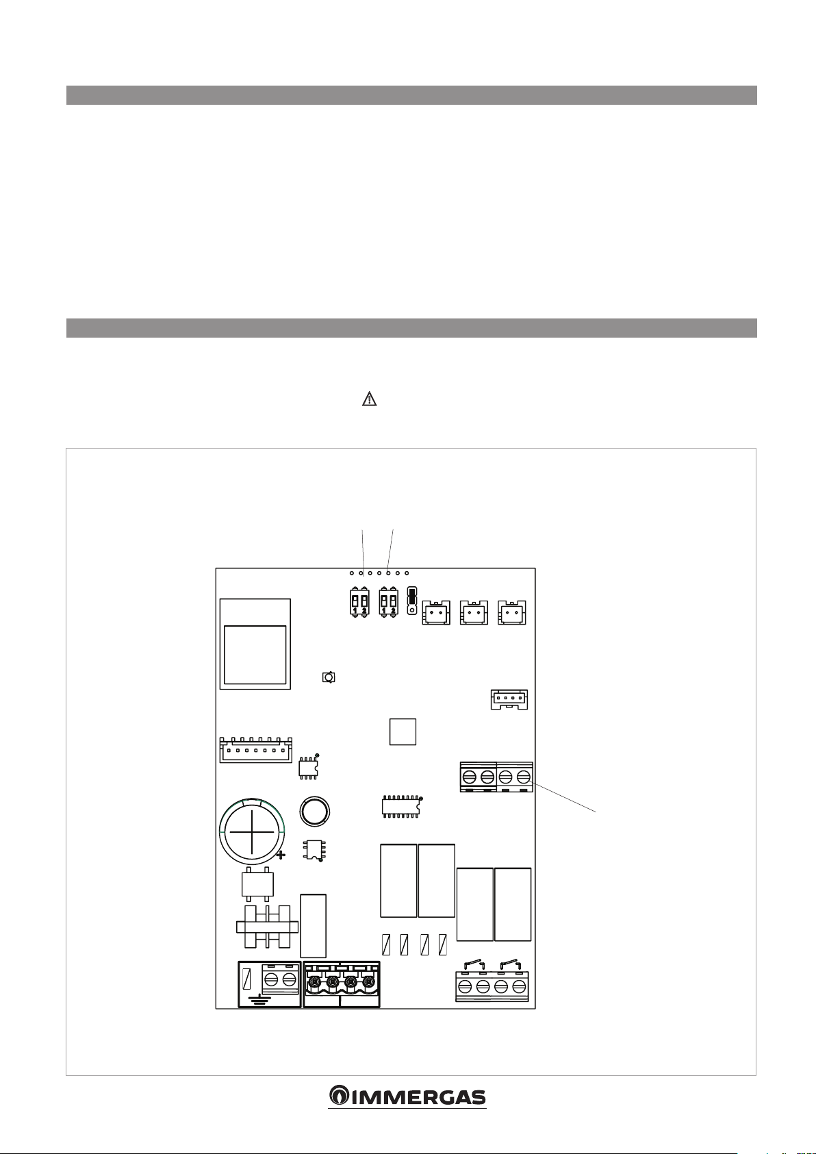
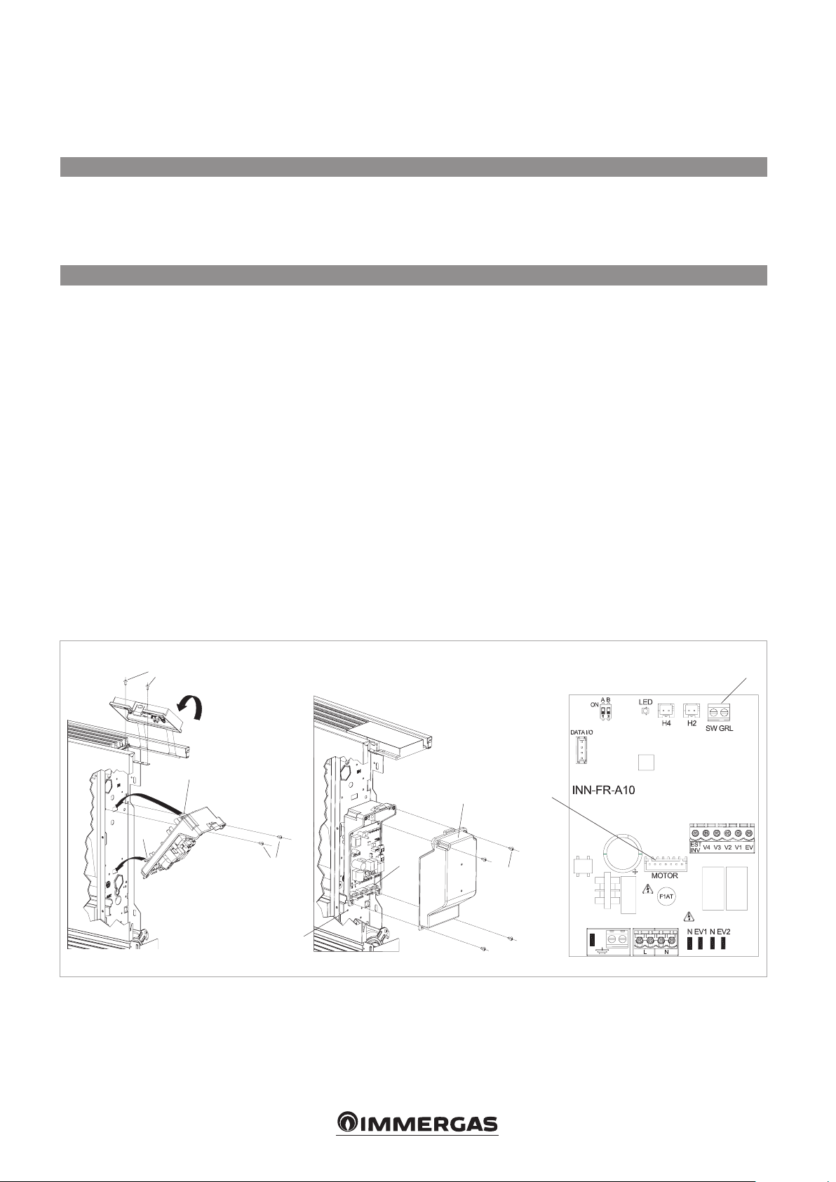
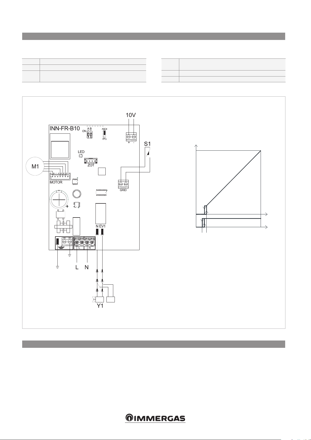
2. MODULATING TEMPERATURE CONTROLLER KIT
2.1 Assembly, set-up and connection
The controllers have two independent clean contacts for
controlling a refrigerator unit, a boiler and a presence input.
The 2 tube versions have a 230V output to power the
summer and winter solenoid valve.
The 10 kΩ water temperature probe positioned in the
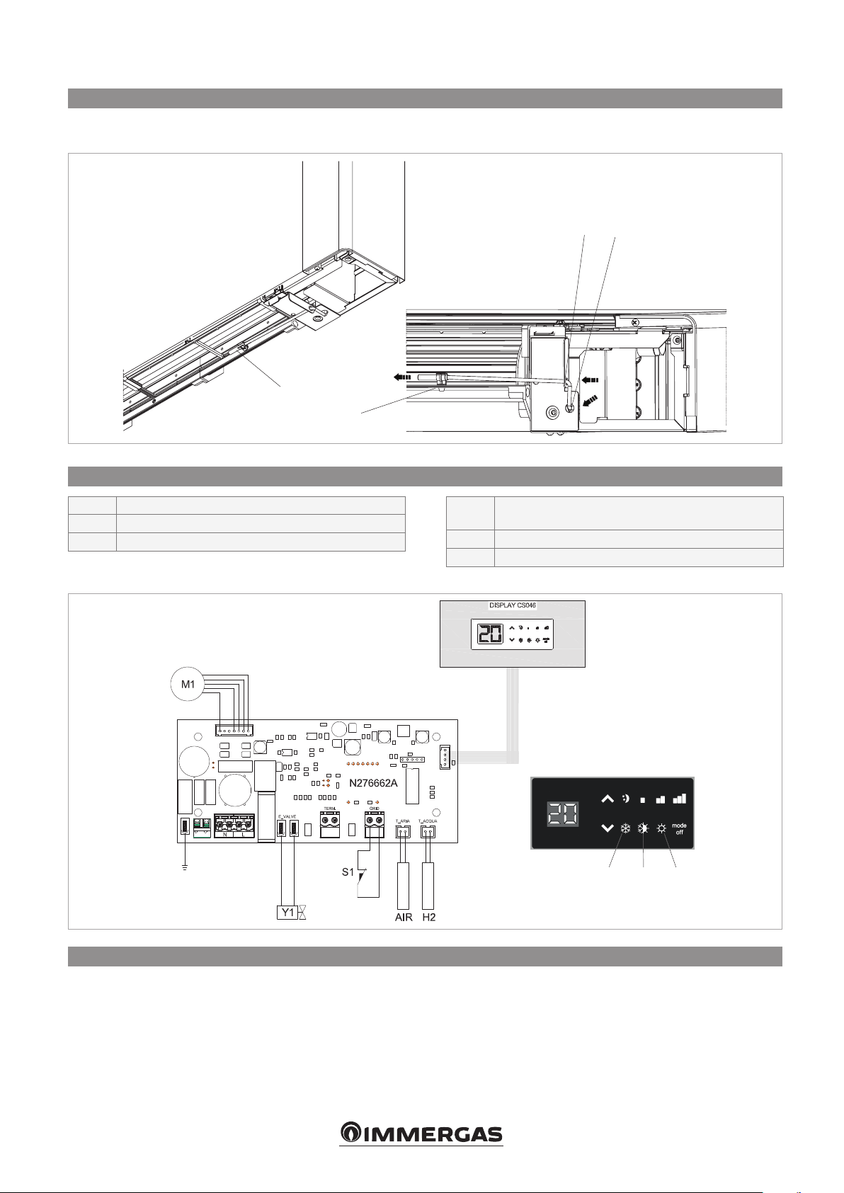
2.2 Assembly
Slide the control panel into its housing in the upper part
of the device and fix it with the two fixing screws (ref. A).
To install the connection box:
- open the box (ref. B);
- lock the lower tooth into its hole (ref. C) on the side of
the device;
- hook the upper part of the box to the side (ref. D);
- fix it with the two fixing screws (ref. E);
- connect the grounding cable to the fan coil body (ref. M)
using the fixing screws (the minimum force that must be
applied for tightening screws must be around 2N);
- connect the fast connector of the MOTOR to the other
on the board (ref. I) *;
- on the two GRID block terminals (ref. L) there is a bridge
which must not be removed.
- For other versions, remove the bridge and connect the
two terminals originating on the grill safety microswitch*;
compartment on the battery regulations the minimum level
when heating (30°C) and the maximum level when cooling
(20°C).
The board also has a function when there is no water
probe, in such cases the fan stop thresholds are ignored.
- connect the water probe to the H2 connector on the
device.
The water temperature probe controls the temperature
inside the batteries and determines when the fan starts
according to pre-set parameters (minimum operation
in winder and maximum in summer).** Check that
they are correctly inserted into the compartment on
the battery.
- Connect the electrics, tidy cables and fix them with
the three clevises supplied (ref. G);
- close the box with the 4 screws (ref. H);
- refit the vanity plate on the side of the unit;
- tighten the upper screws on the control panel;
- place the screw head covers in their housing on the
control panel;
* For versions with hydraulic connections on the right,
refer to the relevant paragraph
** The regulation also works without a water probe
connected
A
D
B
C
E
G
H
I
L
M
6
Page 7
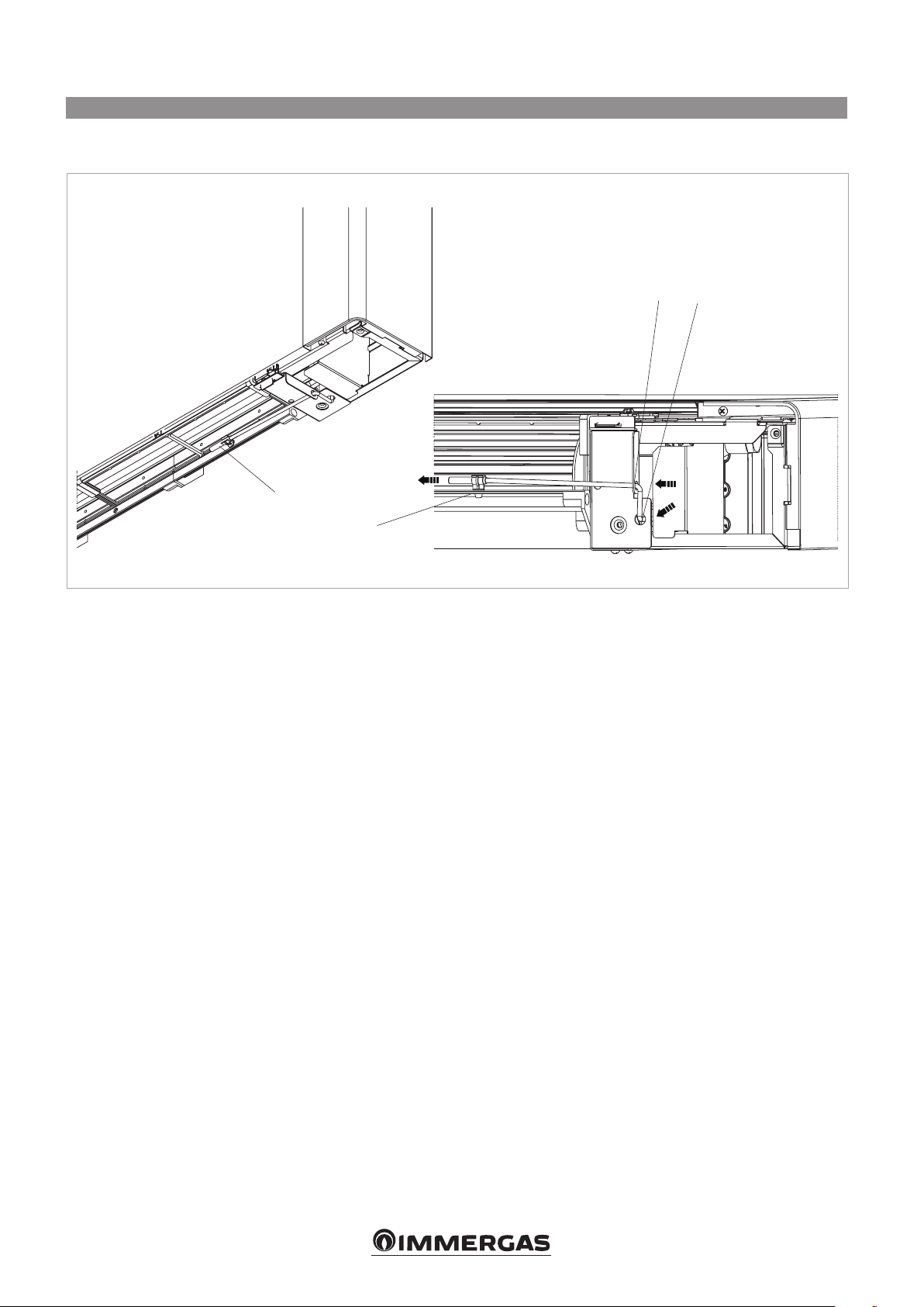
2.3 Set-up of auxiliary dip-switch functions B and C
There are two dip switches on the controller circuit board
for configuring unit operation as per requirements.
- The night-time heating operation logic is modified by
using dip switch C:
- in the ON position, the fan is always off, and heats the
room using radiation and natural convection, as with
traditional radiators; in the off position it operates as a
normal fan.
- By positioning dip switch B to ON, when cooling, the
fan operates at the minimum speed even after having
2.4 CP presence contact input connection
On closing the contact connected to the CP input (ref. A)
the panel is placed in stand-by mode.
If the contact is open the unit is active, if the contact is
closed it is deactivated when a key is pressed the
symbol flashes.
reached the set point, to allow for more uniform
operation of the temperature probe and to avoid
layering in the air. With the cursor in the OFF position,
the functions are cycled (4 minutes ON, 10 minutes
OFF).
The input cannot be connected in parallel to that of other
electronic boards (use separate contacts).
MOTOR
LED
ON
C
B
C
BA
D
ASCII
RTU
H4 H2 AIR
COMM
GRIDGRIDCP
A
N EV1 N EV2
LN
CHILLER BOILER
7
Page 8
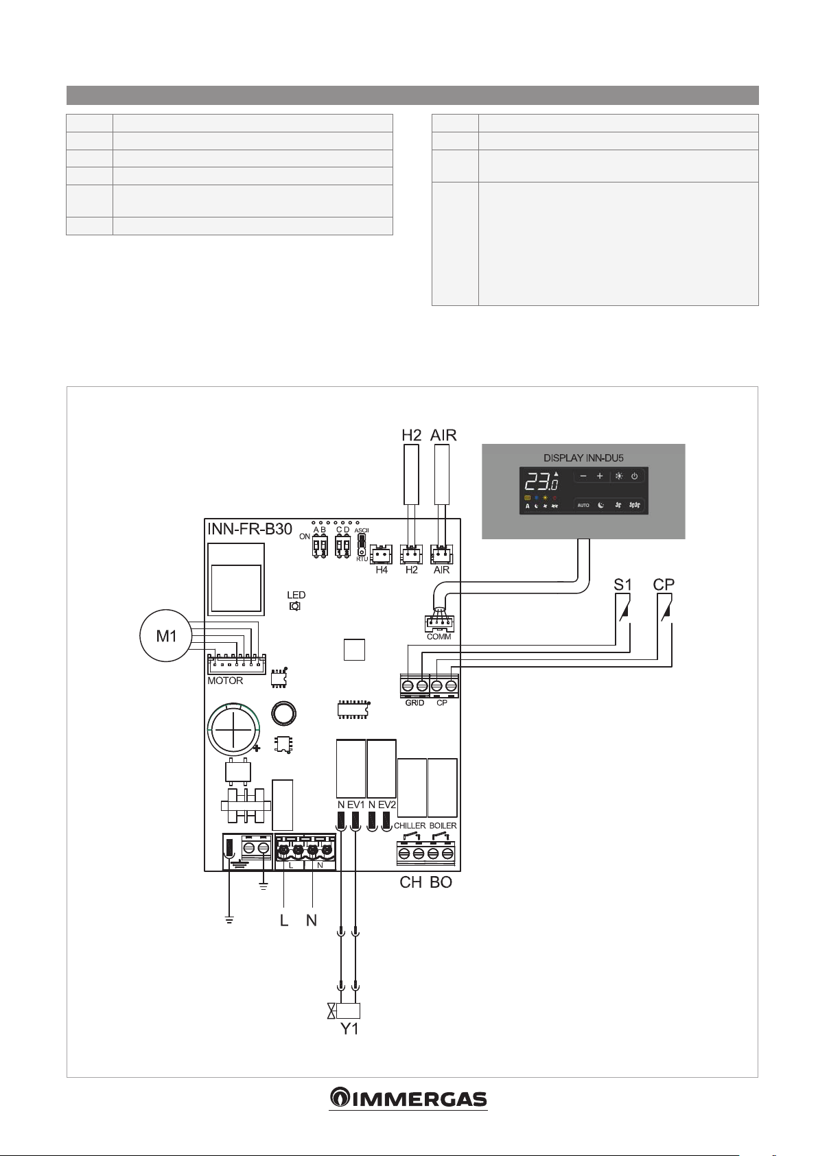
2.5 Air temperature probe assembly
- To position the temperature probe (ref. A):
- pass the probe through the hole on the shoulder (ref. B)
A
D
- insert the probe into the lower hole (ref. C)
- fix the probe on the relevant hook (ref. D)
C
B
8
Page 9
2.6 Connections
H2* water temperature probe 10 kΩ
AIR air temperature probe 10 kΩ
M1 DC inverter fan motor
S1 grill safety micro-switch
Y1
L-N
water solenoid valve (230V/ 50Hz 1A output
voltage)
electrical power supply 230V/50Hz
BO boiler consent output (free contact max 1A)
CH chiller consent output (free contact max 1A)
CP
* If after switching the power on the board detects
presence input sensor (if closed, the fan coil unit
is placed in standby)
the probe, start-up occurs in normal conditions
with the minimum water temperature when
heating (30°C) and maximum when cooling
(20°C).
The board also has a function when there is no
probe, in such cases the fan stop minimum and
maximum thresholds are ignored.
9
Page 10
3. 4-SPEED TEMPERATURE CONTROLLER KIT
3.1 Assembly and connections
The on-board controller with speed selector and ON/OFF
key, room thermostat adjustable from 5 to 40°C, winter
summer selector and minimum winter temperature function
3.2 Assembly
Slide the control panel into its housing in the upper part
of the device and fix it with the two fixing screws (ref. A).
To install the board:
- connect the grounding cable to the unit structure (ref.
M) using the fixing screws (the minimum force that
must be applied for tightening screws must be around
2N);
- connect the fast connector of the MOTOR to the other
on the board (ref. I) *;
N.B.: should the board not be fitted in the factory, the
fan motor must be rotated 180° due to the length of
the standard fan coil cable.
- on the two GRID block terminals (ref. L) there is a
bridge which must not be removed.
- For other versions, remove the bridge and connect the
two terminals originating on the grill safety microswitch;
N.B.: should the two brown terminals on the unit be
too short, replace them with those included in the kit
packaging.
- connect the water probe connector H2 (ref. F) on the
(30°C) and maximum summer temperature (20°C) is suitable
for fitting on board the unit and has a 230V - 1A output for
controlling a solenoid valve.
unit.
The water temperature probe controls the temperature
inside the batteries and determines when the fan
starts according to pre-set parameters (minimum
operation in winter and maximum in summer). Check
that they are correctly inserted into the compartment
on the battery.
- make the electrical connections, tidy the cabling;
- refit the vanity plate on the side of the unit;
- tighten the upper screws on the control panel;
- place the screw head covers in their housing on the
control panel;
- * For versions with hydraulic connections on the
right, refer to the relevant paragraph.
A
M
10
L
F
Page 11
3.3 Air temperature probe assembly
- To position the temperature probe (ref. A):
- pass the probe through the hole on the shoulder (ref. B)
A
D
3.4 Connections
H2 water temperature probe 10 kΩ
M1 DC inverter fan motor
S1 grill safety micro-switch
- insert the probe into the lower hole (ref. C)
- fix the probe on the relevant hook (ref. D)
C
B
Y1
L-N 230V/50Hz electrical power supply
AIR air temperature probe 10 kΩ
water solenoid valve (230V/ 50Hz 1A output
voltage)
3.5 Water probe kit management
If the board detects the water temperature detecting probe
on the device positioned in the relevant compartment of
the battery, it starts in normal conditions. If the probe is not
connected, its absence is indicated by the blue and red
LEDs flashing together, and operation stops.
To confirm operation without the probe, press and hold the
summer/winter button for 5 seconds (ref. A).
This condition is saved by the board for future start-ups.
C A D
In any case, as and when the probe is connected, the unit
returns to normal operation with temperature thresholds.
If the unit operates with the probe connected and the water
temperature is not suitable for active functioning (over 20°C
when cooling, under 30°C when heating) the fan will stop
and the anomaly will be indicated by the corresponding LED
flashing (cooling: blue C or heating: red D).
11
Page 12
4. UNIVERSAL CARD KIT FOR COMMERCIAL TEMPERATURE
CONTROLLER
4.1 Assembly and connections
Assembled on-board the unit, this card allows the regulation
of the motor with fixed speeds; it can be combined with
control panels with thermostat and with all control panels
4.2 Assembly
Slide the blanking panel into its housing in the upper part of
the device and fix it with the two fixing screws (ref. A).
To install the connection box:
- open the box (ref. B);
- lock the lower tooth into its hole (ref. C) on the side of
the device;
- hook the upper part of the box to the side (ref. D);
- fix it with the two fixing screws (ref. E);
- connect the grounding cable to the unit body (ref. M)
using the fixing screws (the minimum force that must be
applied for tightening screws must be around 2N);
- on the two SW GRL block terminals (ref. L) there is a
bridge which must not be removed.
available in the market.
It has a 230 V output to pilot the summer and winter solenoid
valve.
- For other versions, remove the bridge and connect the
two terminals originating on the grill safety microswitch*;
- connect the fast connector of the MOTOR to the other
on the board (ref. I);
- Connect the electrics, tidy cables and fix them with
the three clevises supplied
- close the box with the 4 screws
- refit the vanity plate on the side of the unit;
- tighten the upper screws on the blanking panel;
- place the screw head covers in their housing on the
blanking panel;
* For versions with hydraulic connections on the right,
refer to the relevant paragraph.
(ref. G)
;
(ref. H)
;
A
L
D
B
I
C
E
G
H
M
12
Page 13
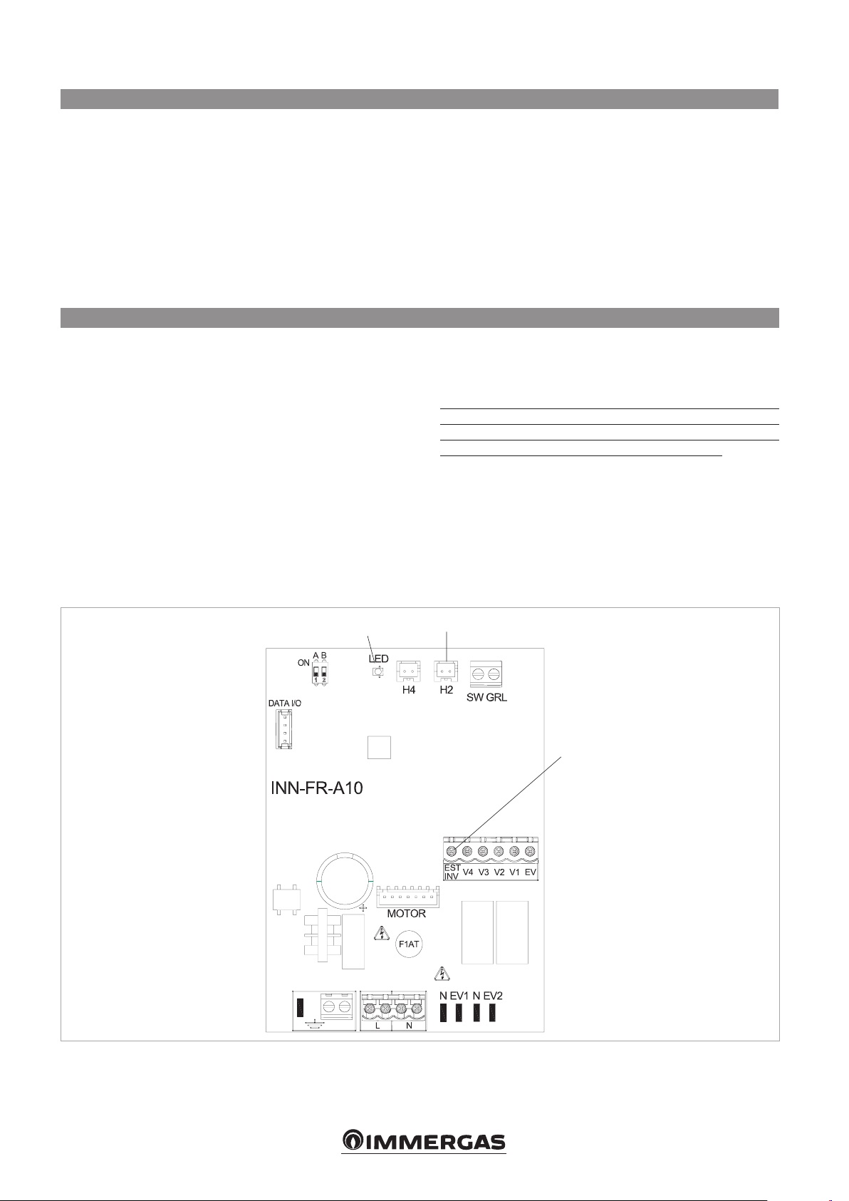
4.3 Connection diagram with 3-speed thermostat
Make the electrical connections to a thermostat fit for use
according to the diagram.
L-N electrical supply 230V-50Hz
EV solenoid valve permission input
V1 maximum fan speed
V2 medium fan speed
V3 minimum fan speed
V4 supersilent speed
E
Y2
Y1
heating selection input, cooling
See paragraph on Water Probe Management
output for mobile suction panel servo (power
output 230V/ 50Hz 1A)
water solenoid valve (230 V/ 50 Hz 1A output
voltage)
M1 DC inverter fan motor
S1 safety micro-switch for grill
3-speed room thermostat (to be purchased,
TA
CV thermostat permission
SV speed selector
H2* water temperature probe (10 kΩ)
*
installation and connection to be made by
installer)
positioned in the on-board battery.
See paragraph on Water Probe Management
4.4 Connections with 3-speed thermostats
The CV input is the board ON/OFF which when open puts
the board in stand-by. It must be bridged to the L terminal
on the 230V power supply to activate solenoid valve Y1.
The 4 speed inputs V1, V2, V3 and V4, when bridged
to the L terminal on the 230V power supply, activate the
fan if the S1 input to which the grill safety microswitch is
connected is closed. The sequence is: maximum speed
(1400 rpm on terminal V1), medium speed (1100 rpm on
terminal V2), minimum speed (680 rpm on terminal V3)
and supersilent speed (400 rpm on terminal V4).
Connect the three thermostat speeds to 3 out of the 4
available inputs as per the characteristics and use of the
room: connect, for example, medium speed V2, minimum
V3 and supersilent V4 for residential applications, when
greater silence is required, whereas V1, V2 and V3 can be
connected for commercial applications where the thermal
yield is more important.
If multiple inputs are simultaneously closed, the motor will
run at a number of revs equal to that of the connection
with the highest speed.
Multiple cards can be connected in parallel to a single
thermostat, also using different speeds.
13
Page 14
4.5 LED signals
The LED (ref. A) is off if the CV input is not closed (stand-by
condition).
It turns on when the CV contact is closed and indicates
normal operation.
• Flashes frequently if the grille microswitch S1 is activated
due to the filter cleaning operation
• 1 flash + pause indicates a fan stoppage alarm due to
unsuitable water (with H2 water probe connected).
• 2 flashes + pause due to a motor alarm (e.g. blockage
caused by foreign objects, faulty rotation sensor).
4.6 Water probe management with 3-speed thermostat
If the board is used with electromechanical thermostats, or with
other commercial controllers with water probe, the on-board
probe H2 should not be connected and the fan is controlled by
the remote control.
If on the other hand the controller is not set up for managing the
water probe, this function can be performed by the board, by
connecting the 10 kΩ probe on the battery to the H2 connector
on the board (ref. B).
In this case the board carries out the minimum temperature
function for heating operations and maximum temperature
function for cooling. Therefore, if the water temperature is not
suitable for active operation (above 20°C when cooling, under
30°C when heating) the fan is stopped and the anomaly is
signalled by a single flash + pause of the LED (ref. A).
• 3 flashes + pause indicates a disconnected or faulty
water probe alarm.
The discrimination between heating/cooling is actuated via the
Summer-Winter (ref. C) input of the board: leaving it open the
board activates heating, closed activates cooling.
If after having connected the probe it is disconnected or
measures incorrect values (e.g. installation of 2 kΩ probe in the
place of the 10 kΩ probe) the anomaly is signalled by 3 flashes
+ pause of the LED (ref. A) and operation is stopped.
To confirm operation without a probe, turn the power to the
board off and then on again.
This condition is saved by the board for future start-ups.
In any case, as and when the probe is connected, the unit
returns to normal operation with temperature thresholds.
A
B
C
14
Page 15

5. 0-10 V DEMAND BOARD KIT
5.1 Assembly and connections
When fitted on board the machine it allows for managing the
motor, with modulated speed; motor regulation can be made
using an analogue 0-10V DC input with 25 kΩ impedance.
5.2 Assembly
Slide the blanking panel into its housing in the upper part of
the device and fix it with the two fixing screws (ref. A).
To install the connection box:
- open the box (ref. B);
- lock the lower tooth into its hole (ref. C) on the side of
the device;
- hook the upper part of the box to the side (ref. D);
- fix it with the two fixing screws (ref. E);
- connect the grounding cable to the unit structure using
the fixing screws (the minimum force that must be
applied for tightening screws must be around 2N);
- on the two GRID block terminals (ref. I) there is a bridge
which must not be removed.
A
For board control outputs these impedance values must be
considered, especially when controlling more than one unit
in parallel.
It has a 230 V output to pilot the solenoid valve.
- For other versions, remove the bridge and connect the
two terminals originating on the grill safety microswitch;*
- connect the fast connector of the MOTOR to the other
on the board (ref. H);
- Connect the electrics, tidy cables and fix them with
the three clevises supplied
- close the box with the 4 screws
- refit the vanity plate on the side of the unit;
- tighten the upper screws on the blanking panel;
- place the screw head covers in their housing on the
blanking panel;
* For versions with hydraulic connections on the right,
refer to the relevant paragraph.
(ref. F)
;
(ref. G)
;
D
C
E
5.3 LED signals
The LED (ref. L) is off is the input signal is less than 0.9V.
It turns on with values greater than 1V and indicates normal
operation.
• Flashes frequently if the grille microswitch S1 is activated
due to the filter cleaning operation
L
H
I
B
F
G
• 2 flashes + pause due to a motor alarm (e.g. blockage
caused by foreign objects, faulty rotation sensor).
15
Page 16
Y2
)
5.4 Connection diagram with 0-10V DC thermostats / signals
Make the electrical connections to a thermostat fit for use
according to the diagram
L-N Electrical power supply 230V-50 Hz
10V Appliance piloting input 0÷10 V
Y1
water solenoid valve (230V/ 50Hz 1A output
voltage)
Input impedance 25 kΩ
Y2
M1
S1 safety micro-switch for grill
output for mobile suction panel servo (power
output 230 V/ 50Hz 1A)
DC inverter fan motor
OUTPUT FEATURES
MAX rpm
M1
MIN rpm
5.5 Connections with 0-10V thermostats
The 10V input, if the S1 input which the grill safety micro
switch is connected to is closed, activates solenoid valve Y1
and regulations fan revolutions.
The speed "ramp" provides for linear regulation from the
minimum value (400 rpm) to the maximum value (1,400 rpm)
ON
Y1
OFF
0
1
1,1
0,9
for voltage values ≥ 1.1V÷10 V DC.
The motor is off when values are lower than 1V DC.
The Y1 solenoid valve is activated for power values > 1V
DC and switches off then the power drops below 0.9V
DC.
10
10 V
INPUT
(V DC
16
Page 17

6. FEET KIT
6.1 Assembly
This instruction is an integral part of the booklet of the
appliance on which the kit is installed. Please consult this
booklet for general warnings and fundamental safety rules.
These accessories cover the hydraulic pipes coming
up through the floor. They should be fitted on Hydro FS
appliances anchored to the back wall.
They have a sleek design and are also easy to remove for
maintenance or cleaning.
A threaded supports B supports cover
These Feet should not be used to anchor the terminal to
the ground.
- Rest the back of the appliance on a horizontal surface;
- screw the four threaded supports provided to the
structure;
- stand the appliance up again and fasten it to the wall;
- fit the two covers to the supports.
A
A
B
B
17
Page 18

7. 2-WAY/3-WAY VALVE UNIT KIT
To avoid penalising the performance of the system the
water inlet and outlet must be as indicated in the various
figures.
For a rapid and correct assembly of the components
follow carefully the sequences described in the various
sections.
This instruction is an integral part of the booklet of the
appliance on which the kit is installed. Please consult this
booklet for general warnings and fundamental safety rules.
7.1 List of hydraulic accessories
- 2-way valve unit with thermo-electric head kit. - 3-way deviator valve unit with thermo-electric head
deviator valve kit.
7.2 Pipeline diameter
The minimum internal diameter that must be respected for
the pipelines of the hydraulic connections varies according
U.M. 200 400 600 800 1000
support covers mm 12 14 16 18 20
to the model:
7.3 Access to inner parts
- Lift it up the side panels.
- Move orizzontally to remove.
A Left panel
B Right panel
18
Page 19

7.4 Mounting the thermostatic head
Tighten the plastic disc to the valve body. Attach the head
to the valve body.
To facilitate the system mounting, filling and venting
operations, even without electric power, the thermostatic
head is supplied with a tool that keep it open.
A plastic tool
B valve body
C
B
Remove the tool from the thermostatic head before
starting the system.
C thermostatic head
A
7.5 Lockshield adjustment
The lockshields supplied with the hydraulic kits provide
an adjustment that balances the system load losses. To
ensure a correct adjustment and balancing of the circuit,
follow the procedure indicated below:
- With a screwdriver, loosen and remove the slotted
grub screw inside the hexagonal head.
- Close the adjustment screw using a 5 mm Allen key
(A)
- Re-tighten the slotted grub screw then mark the
reference point for the adjustment with an “x” (B).
- Align the screwdriver with the “x”, then open with
a number of turns (C) according to diagram Äp-Q
shown on page 22.
The number of turns refers to the micrometric screw
Then fully open the screw (D). Now the pre-adjustment
has been set and will not change if there are repeated
openings or closings with the Allen key.
19
Page 20

Load losses based on the adjustment of the lockshield
present in all kits.
20
Page 21

mbar
1000
900
800
600
700
400
200
100
80
60
40
20
10
8
6
4
2
500
300
90
70
50
30
P
9
7
5
3
1
20
40
60
80
30
50
70
90
100
200
400
600
800
1000
300
500
700
900
3000
2000
qm = kg/h
0.1
0.2
0.3
0.5
0.7
0.9
0.4
0.6
0.8
1
2
4
3
5
7
9
6
8
10
30
20
40
60
80
100
50
70
90
kPa
KV
s
4000
KVS = 3,60
7.6 Way valve with thermo-electric head kit
Consists of an automatic valve with thermo-electric head
and a lockshield, fitted with micrometric adjustment,
capable of balancing the system load losses.
load losses in completely open position of 2-way valve
present in kits.
The kit contains the insulation to be mounted on the valve
and on the lockshield.
21
Page 22

7.7 Way valve with thermo-electric head deviator valve kit
Consists of a 3-way deviator valve with thermo-electric
head and a lockshield, fitted with micrometric adjustment,
capable of balancing the system load losses).
Diagram of load losses of deviator valve, present in kit, in
completely open position.
The kit contains the insulation to be mounted on the valve
and on the lockshield.
22
Page 23

Diagram of load losses of deviator valve, present in kit, in
completely closed position.
23
Page 24

A
7.8 Connections
The choice and sizing of the hydraulic lines must be made
by an expert who must operate according to the rules of
good technique and the laws in force.
To make the connections:
- position the hydraulic lines
- tighten the connections using the “spanner and
counter spanner” method
- check for any leaks of liquid
- coat the connections with insulating material
A Eurokonus adapter
B Spanner and counter spanner
The hydraulic lines and joints must be thermally insulated.
Avoid partially insulating the pipes.
Do not over-tighten to avoid damaging the insulation.
Use hemp and green paste to seal the threaded
connections; the use of Teflon is advised when there is
anti-freeze in the hydraulic circuit.
C Coat the connections with insulating material
B
C
24
Page 25

7.9 2-way valve unit kit
Consists of an automatic valve with thermo-electric head
and a lockshield, fitted with micrometric adjustment,
capable of balancing the system load losses.
- Remove the side panel as indicated in paragraph Side
opening.
- Assemble the components as indicated in figure
- Apply the supplied insulation.
1 thermo-electric head (n.1)
2 lockshield (n.1)
3 2-way valve (n.1)
The kit contains the insulation to be mounted on the valve
and on the lockshield.
When the hydraulic components have been mounted,
connect the thermo-electric head connectors with the
wiring connectors on the machine.
X thermo-electric head connectors
Y wiring connectors
1
3
2
X
Y
25
Page 26

7.10 3-way valve unit kit
Consists of an automatic 3-way diverter valve with thermo-electric
head and a lockshield, fitted with micrometric adjustment, capable
of balancing the system load losses. The kit contains the insulation
to be mounted on the valve and on the lockshield.
- Remove the side panel as indicated in paragraph Side
opening.
Floor mounted version
1 thermo-electric head (n.1)
2 lockshield (n.1)
3 3-way valve (n.1)
4 outlet union (n.1)
- Assemble the components as indicated in figure
- Apply the supplied insulation.
When the hydraulic components have been mounted,
connect the thermo-electric head connectors with the
wiring connectors on the machine.
5 1/2” flexible tube 230 (n.1)
X thermo-electric head connectors
Y wiring connectors
1
3
5
4
2
X
Y
26
Page 27

8. COOLER-CONVECTOR, HEATING, COOLING AND DEUMIDIFICATION
8.1 Fundamental safety rules
Do not allow children or unassisted disabled people to use
the unit.
Do not open the access covers and carry out technical or
cleaning activities before disconnecting the unit from the power
grid by positioning the system’s main switch in the “off” position.
It is forbidden to modify the safety or regulation devices without
the authorisation and directions of the manufacturer.
Do not stand, sit and/or place objects on the unit.
Do not pull, detach or twist the electrical wires coming out of
the unit, even when the unit is disconnected from the power grid.
8.2 Description
Do not spray or throw water directly on the unit.
Do not dispose of, abandon or leave the potentially hazardous
packaging materials within the reach of children.
It is strictly forbidden to touch any moving parts, interfere with
them or introduce pointed objects through the grids.
Do not touch the unit while barefoot and/or partially wet.
The device is a terminal facility that contains in a single
device the best solution for the heating, cooling and
dehumidification. Allows you to achieve energy efficiency
very high for the possibility of being coupled with
generators of heat at low temperature such as: heat
pumps, condensing boilers integrated systems withsolar
collectors. Thanks to a sophisticated temperature
controller, the device, providing excellent thermal comfort
in every season. Heats and cools very rapidly and once it
reaches the desired temperature, keeps it very precisely
in utter silence. In heating mode, the device develops
an effective natural convective effect (similar to that of a
radiator) which greatly reduces the need to activate the
ventilation. Its harmonious design and exceptionally low
depth of only 15 cm make it integrated into any type of
environment for all furnishing needs.
The unit combined with different control panels on board
have the factory settings with parameters for maximum
speed to 1700 rpm. To modify these parameters follow
the procedures contained in instructions supplied with the
control panel.
27
Page 28

8.3 Identification
Technical Tag
The technical tag shows all technical and performance
data of the unit. Should the tag get lost, please ask for a
duplicate tag from the Technical Service.
Any tampering with, the removal or the lack of the
Technical Tag or of any other element whose absence
prevents certain identification of the product makes it
more difficult to install and maintain the product.
Main components:
A
B
D
E
F
H
I
L
M
N
P
Structure
Heat exchanger
Fan unit
Electric motor controlled by INVERTER
Supply air grille reversible
Drain pan
Back structural
Front cover
Removable side panels
Air filter
R version micro-fan
28
Page 29

8.4 Charts of Water flow - Pressure drop
Pressure drop [hPa]
Pressure drop [hPa]
Water ow [l/h] Water ow [l/h]
29
Page 30

8.5 Dimensions
Size 23 45 64 76 94
Dimensions
A mm 140
B mm 80
C mm 20
D mm 20
E mm 400
Dimensions: Tivano - Tivano R
L mm 723
Net weight
Kg 17
923 1123
20 23
1323 1523
26 29
30
Page 31

8.6 Product delivery
Preliminary instructions
We suggest to take the equipment out of its packaging
only when it has been placed in position at the
installation point.
Carefully remove any adhesive strips positioned on the
unit.
Scope of supply
Also supplied:
8.7 Handling and transportation
The unit must be handled by skilled technicians,
appropriately equipped and with the appropriate tools
to manage the unit’s weight in compliance with the
accident prevention regulations.
8.8 Access to inner parts
- Lift it up the side panels.
- Move orizzontally to remove.
Do not dispose of, abandon or leave the potentially
hazardous packaging materials within the reach of
children.
A Left panel
B Right panel
31
Page 32

8.9 Installation
Preliminary instructions
The place of installation must be determined by the
system’s designer or by an expert in the field and must
take into account the technical requirements and the
current standards and legislation.
Before starting installation, decide the placement of the
unit taking into account the minimum required distances.
Detailed information on the unit (measurements,
dimensions, fastenings, required distances, etc.) are
shown in the “Technical Data” chapter.
The unit is designed for vertical installation on the floor.
In order to guarantee the correct operation of the
equipment, the units must be installed so that the air outlet
and inlet shall remain unobstructed.
In case of concealed installation a detachable section
cut into the suspended ceiling is required in order to
access the unit.
8.10 Minimum installation distances
Figure indicates the minimum mounting distances
between the wall-mounted cooler-convector and furniture
present in the room.
The unit must be mounted so as to guarantee the
circulation of the processed air throughout the whole
environment.
Check that:
- The support wall can support the weight of the unit.
- The wall section does not include bearing elements,
pipes or electric lines.
We suggest to avoid:
- Sunbeams and nearness to heat sources.
- Damp environments and locations where the unit
might come into contact with water.
- Environment containing oil vapours
- Environment contaminated by high frequencies
The following descriptions of the various phases of
assembly and the related drawings refer to a version of
the machine with connections on the left.
32
Page 33

8.11 Vertically mounted
When mounting on the floor with support feet, refer to
the individual instructions leaflets supplied and the relative
manual for the mounting of the feet.
- Using the paper template, trace the position of the
two fixing brackets on the wall.
- Use a suitable drill to make the holes with and insert
the toggle bolts (2 for each bracket); fix the two
brackets. Do not over-tighten the screws so that the
brackets can be adjusted with a spirit level.
A Toggle bolts B Brackets
- Fully tighten the four screws to block the two brackets.
- Check the stability by manually moving the brackets
to the right and to the left, up and down.
- Mount the unit, checking that it fits correctly onto the
brackets and checking that it is stable.
33
Page 34

8.12 Hydraulic connections
Size 23 45 64 76 94
Pipes
Diameter mm 12 14 16 18 20
The choice and sizing of the hydraulic lines must be made
by an expert who must operate according to the rules of
good technique and the laws in force.
To make the connections:
- Position the hydraulic lines
- Tighten the connections using the “spanner and
counter spanner” method
- Check for any leaks of liquid
- Coat the connections with insulating material.
Accompanying this unit there are two adapters to transform
A
Eurokonus adapter
the 3/4” Eurokonus connections in 3/4” BSP. In this case
use hemp and green paste or similar to seal the threaded
connections; the use of Teflon is advised when there is
anti-freeze in the hydraulic circuit.
The hydraulic lines and joints must be thermally
insulated.
Avoid partially insulating the pipes.
Do not over-tighten to avoid damaging the insulation.
34
Page 35

8.13 Condensation discharge
The condensation discharge network must be suitably
sized and the pipeline positioned so that it keeps a
constant inclination, never less than 1%.
In the vertical installation, the discharge pipe (16 mm
diameter) is connected directly to the discharge tray,
positioned at the bottom of the side shoulder underneath
the hydraulic fixtures.
- If possible, make the condensation liquid flow directly
in a gutter or a “rainwaters” discharge.
- When discharging directly into the main drains, it is
advisable to make a siphon to prevent bad smells
returning up the pipe towards the room. The curve
of the siphon must be lower than the condensation
collection bowl.
- If the condensation needs to be discharged into a
container, it must be open to the atmosphere and
the tube must not be immerged in water to avoid
problems of adhesiveness and counter-pressure that
would interfere with the normal outflow.
- If there is a height difference that could interfere with
the outflow of the condensation, a pump must be
mounted:
- In a vertical installation mount the pump under the
lateral drainage tray;
A
B
Discharge fitting
Pipe for the flow of liquid
Such pumps are commonly found in commerce.
However, on completion of the installation it is advisable
to check the correct outflow of the condensation liquid by
slowly pouring about ½ l of water into the collection tray in
about 5-10 minutes.
Mounting the condensation discharge pipe in the
vertical version
Connect to the condensation collection tray discharge
union a pipe for the outflow of the liquid blocking it
adequately. Check that the drip-collector extension is
present and correctly installed.
Make sure that the machine is installed perfectly level
or with a slight inclination towards the condensation
discharge;
Insulate carefully the inflow and outflow pipes up to
the machine union to prevent any drops of condensation
outside the same collection bowl;
Insulate the bowl condensation discharge pipe along
all of its length.
C
Extension drip
35
Page 36

8.14 Electrical connections
Preliminary instructions
Detailed information on the unit (measurements,
dimensions, fastenings, required distances, etc.) are
shown in the “Technical Data” chapter.
The manufacturer waives all liability for damages
caused by lack of grounding or departure from the
electrical diagrams.
Check that:
- The characteristics of the power supply network shall
be appropriate for the unit’s power requirements,
taking into account also other equipment which might
be operated in parallel.
- Electrical voltage shall be equal to the nominal value
+/- 10%, with a maximum phase unbalance of 3%.
Mandatory items:
- The use of an omnipolar magnetothermic switch,
lockable line disconnector, compliant with CEI-EN
8.15 Filling the system
When starting up the system, make sure that the hydraulic
unit lockshield is open. If there is no electric power and the
thermo-valve has already been powered use the special
cap to press the valve stopper to open it.
standards (contacts open by at least 3 mm), with
adequate disconnection power and differential
protection in compliance with the electrical data table
below, installed next to the unit.
- Ground the unit thoroughly.
Do not use gas and water pipes to ground the unit.
Connection
Make electrical connections according to the
requirements set out in sections General Warnings and
Foundamental Safety Rules by reference to the patterns
present in the installation and accessories manuals.
Before doing any work, make sure the power is
switched off.
36
Page 37

8.16 Evacuation of air when filling system
- Open all the system interception devices (manual or
automatic);
- Start the filling by slowly opening the system water
filling tap;
- For the installed in a vertical position, take a screwdriver
and act on the highest breather of the battery.
8.17 First commissioning
Preliminary instructions
Check that:
- All safety conditions have been fulfilled
- All connections have been made correctly
- The hydraulic test of the circuit and condensate
discharge has been done successfully.
- Grounding has been done correctly.
- All connections have been fastened well.
A Venting of the battery
- When water starts coming out of the breather valves
of the appliance, close them and continue filling until
reaching the nominal value for the system.
Check the hydraulic seal of the gaskets.
It is advisable to repeat these operations after the
appliance has been running for a few hours and periodically
check the pressure of the system.
Start
- Position the unit’s main switch in the “on” position.
- Turn the unit on with the control.
- Check performance in the various modes.
Please consult the instructions for information on how
to use the control.
37
Page 38

A
B
9. MODULATING TEMPERATURE CONTROLLER KIT
9.1
SMART TOUCH electronic control panel
These controls make room temperature adjustment (with
offset settable from the keyboard) completely autonomous
through the AUTO, SILENT, NIGHT and MAX programmes
by means of a probe located in the lower part of the device,
ensuring anti-freeze safety even when set to stand-by.
The control panel has a memory, so settings will not be
lost if the appliance is switched off or in the power supply
is cut.
9.2
Display
After 20 seconds from the last action the panel
brightness will be reduced for improved night-time
comfort, and the room temperature will appear on the
display. Press any key to restore maximum brightness.
The 10 kΩ water temperature probe positioned in the
device battery regulations the minimum level when heating
(30°C) and the maximum level when cooling (20°C).
A Display
B Keys
Any statuses and alarms are also shown on the display by
using 8 specific symbols:
Automatic operation
Silent operation
Maximum ventilation speed
Night-time operation
Heating on
9.3 Key function
The various functions are set using 8 backlit keys:
Temp + is for increasing the set temperature
Temp - is for decreasing the set temperature
Heating / Cooling: for changing the operation
mode between heating and cooling
Sets the regulation ventilation speed between
a minimum and maximum value to an entirely
automatic mode
Cooling on
Supervision on Flashing with presence switch CP
closed.
Alarm indicator (solid light)
Panel off indicator
Resistance active indicator
Night-time operation: limits ventilation speed
to a contained level and the set temperature
is adjusted automatically.
Maximum speed operation: Allows for the
maximum ventilation speed to be set
ON/Stand-By: for activating the device or for
putting it in stand-by.
Silent: limits ventilation speed to a more
contained value
38
Page 39

9.4 General On Switch
In order to manage the device via the control panel, this
must be connected to the mains electricity.
If a general switch is installed on the power line, this must
also be switched on.
- Turn the device on by activating the general
switch.
9.5 Activation
- To activate the device
Key Operation Display
Press the ON Stand-by key
Select one of the 4 operating modes by pressing the relative key.
9.6 Heating/cooling operation modes setting
Key Operation Display
Keep the Heating / Cooling key pressed for approx. 2 seconds to change the mode
between heating and cooling, which is indicated by the 2 symbols that appear if
heating or cooling is active.
When heating, the symbol displays when the set point is higher than ambient
temperature, both are off when the set point is lower.
When cooling, the symbol displays when the set point is lower than ambient
temperature, both are off when the set point is higher.
From off to on
One of the two symbols flashing means that the water
temperature (hot or cold) is not sufficient, and stops
the fan until the temperature reaches a level suitable for
reaching the required temperature.
If after switching the power on the board detects the
H2 probe, start-up occurs in normal conditions with the
minimum and maximum thresholds.
The board also has a function when there is no H2 probe,
in such cases the fan stop thresholds are ignored.
9.7 Stand By
Key Operation Display
Press and hold the ON Stand-By key for approx. 2 seconds. No illuminated signals
on the display at all means that the system is in stand-by (no operation).
When the control is in this operating mode, anti freezing is
in any case guaranteed. If the ambient temperature drops
below 5°C, the solenoid valves on the hot water output
and the boilers are opened.
Off
39
Page 40

9.8 Temperature selection
Key Operation Display
Set the required room temperature using the two increase/decrease keys to set the
temperature value on the 3-digit display.
20.5
The adjustment range is from 16 to 28°C in intervals of
0.5°C, but out-of-range values are also accepted, from
5°C to 40°C (unless in auto mode).
Only set these values for brief periods, and then set a
intermediate value.
The controller is very precise - set it to the required value
and wait for the controller to regulate itself according to the
actual room temperature detected.
9.9 Automatic operation
Key Operation Display
Press and hold the AUTO key. The function being activated is indicated by the
relevant symbol appearing on the display.
Ventilation speed adjustment is carried out automatically
between the minimum and maximum values, according to
the distance of the actual room temperature from the set
point, according to a PI-type algorithm.
9.10 Silent operation
Key Operation Display
Press and hold the Silent key. The function being activated is indicated by the
relevant symbol appearing on the display.
Ventilation speed is limited to a contained maximum value.
9.11 Night-time operation
Key Operation Display
Press and hold the Night-time operation key. The function being activated is
indicated by the relevant symbol appearing on the display.
By selecting this mode, ventilation speed is limited to a
very contained level and the set temperature is adjusted
automatically, as follows:
- decreases by 1°C after one hour and by another
degree after two hours in heating mode;
- increases by 1°C after one hour and by another
degree after two hours in cooling mode;
9.12 Operation at maximum ventilation speed
Key Operation Display
Press and hold the Max Operation key. The function being activated is indicated by
the relevant symbol appearing on the display.
In this operation mode, the maximum possible power level
is activated whether heating or cooling.
Once the desired room temperature is reached, we
recommend selecting one of the other 3 operation modes
for increased comfort and sound levels.
40
Page 41

9.13 Key lock
Key Operation Display
By pressing both the + and - keys for 3 seconds, all keys are locked locally, and
this is indicated by "bL" appearing on the display.
All actions are disabled to the user and whenever any key is pressed, "bL" will
appear. To unlock the keys, repeat the sequence.
9.14 Reduce brightness to minimum
bL
After 20 seconds from the last action, the panel brightness
will be reduced for improved night-time comfort, and the
room temperature will appear on the display.
Key Operation Display
With the display off, press and hold the + key for 5 seconds until "01" is displayed.
Use the - key to change the value to 00 and wait 20 seconds to check the setting
has been accepted.
If this brightness is still disturbing, the display can be
switched off completely.
9.15 Deactivation
Key Operation Display
Press and hold the ON Stand-By key for approx. 2 seconds. No illuminated signals
on the display at all means that the system is in stand-by (no operation).
The controller also ensures anti freezing when in stand-by.
Off
9.16 Room temperature probe regulation offset
As the detection probe is towards the bottom of the
device, the temperature detected may at times differ from
the actual room temperature.
By using this function, the value displayed can be adjusted
in a range from -9/+12 K in intervals of 0.1°C.
Use this adjustment with care, and only after having
actually detected a discrepancy compared with the actual
room temperature using a reliable device!
00
Key Operation Display
With the display off, press and hold the - key for 5 seconds to access the menu
which allows adjustment (using the + and - keys) of the AIR probe offset displayed,
from -9 to +12 K in 0.1 K intervals.
After 20 seconds from the last action, the panel switches off and the setting is
stored.
9.17 Switching off for long periods
When switching off for a season or for holidays, proceed
as follows:
- Deactivate the device
- Turn the general unit switch to off.
- The antifreeze function is not active.
41
00.0
Page 42

9.18 Error signals
Error Display
Faulty room temperature (AIR) probe
Problem with fan motor (e.g. blockage caused by foreign objects, faulty rotation sensor).
Water temperature probe fault for 2-tube versions (H2).
In this case, ensure that the probe installed is 10 kΩ.
Engaging of grill microswitch S1 due to filter cleaning operation
E1
E2
E3
Gr
42
Page 43

A
B
10. 4-SPEED TEMPERATURE CONTROLLER KIT
10.1
LCD electronic control panel
The controller makes the regulation of room temperature
entirely automatic using the set point setting which can be
adjusted between 5°C and 40°C, to one of the 4 speeds
and the summer/winter setting.
As it is connected to the water temperature probe, in
the battery it has the function of detecting the minimum
temperature in winter (30°C) and maximum temperature
in summer (20°C).
The control panel has a memory, so settings will not be lost
if the appliance is switched off or in the power supply is cut.
10.2 LED indications
After 20 seconds from the last action, the panel
brightness will be reduced for improved night-time comfort,
and the room temperature will appear on the display. Press
any key to restore maximum brightness.
A Display
B
Keys and
LEDs
The 6 LEDs display the operational states:
Green symbol minimum speed
Green symbol medimum speed
Green symbol maximum speed
10.3 Key function
The various functions are set using 4 keys:
Temp + is for increasing the set temperature
Temp - is for increasing the set temperature
10.4 General On Switch
In order to manage the fan coil via the control panel, this
must be connected to the mains electricity.
If a general switch is installed on the power line, this must
Green symbol Super silent function
Red symbol heating
Blue symbol cooling
Heating / Cooling: for changing the operation
mode between heating and cooling (2 seconds)
For activating the device, for selecting one of the
4 speeds or for placing in stand-by (2 seconds).
also be switched on.
- Turn the device on by activating the general switch.
43
Page 44

10.5 Activation
To activate the device
Key Operation Display
Press the mode/off key Off → On
Select one of the 4 operating speeds by pressing the relative mode/off key. When
heating, the symbol displays when the set point is higher than ambient temperature,
both are off when the set point is lower. When cooling, the symbol displays when
the set point is lower than ambient temperature, both are off when the set point is
higher.
10.6 Heating/cooling operation modes setting
Key Operation Display
Keep the Heating / Cooling key pressed for approx. 2 seconds to change the mode
between heating and cooling, which is indicated by the 2 symbols that appear if
heating or cooling is active.
One of the two symbols flashing means that the water
temperature (hot or cold) is not sufficient, and stops
the fan until the temperature reaches a level suitable for
reaching the required temperature.
10.7 Stand By
Key Operation Display
Press and hold the mode/off key for approx. 2 seconds. No illuminated signals on
the display at all means that the system is in stand-by (no operation).
10.8 Temperature selection
Key Operation Display
Set the required room temperature using the two increase/decrease keys to set the
temperature value on the 2-digit display.
The adjustment range is from 15 to 30°C in intervals of
1°C, but out-of-range values are also accepted, from 5°C
(Lo) to 40°C (Hi).
Only set these values for brief periods, and then set a
intermediate value.
The controller is very precise - set it to the required value
and wait for the controller to regulate itself according to the
actual room temperature detected.
10.9 Ventilation speed regulation
Key Operation Display
Each time the mode/off button is pressed the fan speed moves between supersilent,
minimum, medium and maximum.
The function being activated is indicated by the relevant symbol appearing on the
display.
On → Off
The super silent setting activates powerful dehumidifying
when cooling and only radiation (with the fan off, and
solenoid valve activated) when heating.
By setting the highest speed, the maximum possible
power level is activated immediately whether heating or
cooling.
Once the desired room temperature is reached, we
recommend selecting one of the other 3 operation modes
for increased comfort and sound levels.
44
Page 45

10.10 Key lock
Key Operation Display
When the increase and decrease keys are pressed simultaneously for 5 seconds,
all keys are locally locked; this is indicated by bL appearing on the display.
All actions are disabled to the user and whenever any key is pressed, "bL" will
appear.
To unlock the keys, repeat the sequence.
10.11 Reduce brightness to minimum
After 20 seconds from the last action, the panel brightness
will be reduced for improved night-time comfort, and the
room temperature will appear on the display.
If this brightness is still deemed to be disturbing, the display
can be switched off completely by pressing the Heating/
Cooling key for 20 seconds until the display shows .
To return to normal minimum brightness, press the
Heating/Cooling button for 20 seconds until the display
shows .
10.12 Deactivation
Key Operation Display
Press and hold the mode/off key for approx. 2 seconds. No illuminated signals on
the display at all means that the system is in stand-by (no operation).
10.13 Switching off for long periods
When switching off for a season or for holidays, proceed
as follows:
- Deactivate the device
- Turn the general unit switch to off.
10.14 Error signals
Off → On
Error Led Display
Faulty room temperature (AIR) probe 6 LEDs flashing (alarm with automatic
reset).
Water temperature probe (H2) positioned in the main battery fault 2 LEDs
flashing (possible manual reset)*.
Problem with fan motor (e.g. blockage caused by foreign objects, faulty
rotation sensor). 4 LEDs flashing simultaneously (alarm with automatic reset).
Water demand (hot or cold) insufficient (above 20°C when cooling, below
30°C when heating).
The LED of the selected function flashes and the fan is stopped until the
water temperature reaches a suitable level to satisfy the demand.
Grill protection micro switch tripped due to accidental opening of the grill or
when filter cleaning is operating.
* If the board detects the water temperature probe on the
device, it starts in normal conditions. If the probe is not
connected, operation can be confirmed without the probe
by pressing the Heating/Cooling key for 5 seconds.
45
E1
E1
E1
o
Gr
Page 46

11. MAINTENANCE
Periodic maintenance is essential to keep the fan coil
always efficient, safe and reliable over time. It must be
11.1 Cleaning the outside
Before every cleaning and maintenance intervention,
disconnect the appliance from the mains by switching
off the master switch.
Wait until the parts have cooled down to avoid the risk
of burns.
11.2 Cleaning air suction filter
After a period of continuous operation and in consideration
of the concentration of impurities in the air, or when he
intends to restart the plant after a period of inactivity,
proceed as described. The periodicity is twice yearly in
normally clean environment.
done at least once a year by a qualified service engineer
Service.
Do not use abrasive sponges or abrasive or corrosive
detergents to avoid damaging the painted surfaces.
When necessary, clean the outer surfaces of the cooler-
convector with a soft cloth damp cloth.
Extraction of filter cells
- Extract the filter, pulling it horizontally outwards.
A Filter
B Lower edge
C
Filter housing
46
Page 47

Cleaning filtering seats
- Suck up the powder with a vacuum cleaner
- Wash the filter with running water without using
detergents or solvents, and leave to dry.
- Remount the filter on the cooler-convector, taking
care to insert the lower flap into its seat.
It is forbidden to use the unit without the net filters.
After finishing the cleaning of the filter, check that the
panel is mounted correctly.
A Filter
B Lower edge
C
Filter housing
11.3 Energy saving tips
- Always keep the filters clean;
- When far possible, keep the doors and windows
closed in the room being conditioned;
- Limit where possible the effect of direct sun rays in the
rooms being conditioned (use curtains, shutters etc.)
47
Page 48

12. TROUBLESHOOTING
In case of water leaks or anomalous functioning
immediately cut off the power supply and close the water
taps.
Should one of the following anomalies occur, contact
Technical Service Assitant or an authorised qualified
person, but do not intervene personally.
12.1 Table of anomalies and remedies
Out of warranty repairs and maintenance can be performed
by Technical Service Assitant or by qualified personnel.
EFFECT CAUSE REMEDY
A delayed activation of
the ventilation respect to
the new temperature or
function settings.
The appliance does not
activate the ventilation.
The ventilation does not
activate even if there is
hot or cold water in the
hydraulic circuit.
The appliance leaks water
during the heating function.
There are formations of
dew on the front panel.
There are drops of water on
the air outlet grill.
The appliance leaks water
only during the cooling
function.
The appliance makes a
strange noise.
The circuit valve needs some time to
open and as a result the hot or cold
water takes time to circulate in the
appliance.
No hot or cold water in the system.
The hydraulic valve remains closed
The fan motor is blocked or burnt out.
The micro-switch that stops the
ventilation when the filter grill is opened
does not close correctly.
The electrical connections are not
correct.
Leaks in the hydraulic connections of
the system.
Leaks in the valve unit. Check the state of the gaskets.
Thermal insulation unstuck.
In situations of high humidity (>60%)
condensation could form, especially at
the minimum ventilation speeds.
The condensation bowl is blocked. Slowly pour a bottle of water in the low part of the
The condensation discharge does not
need an inclination for correct drainage.
The connection pipes and the valve unit
are not insulated well.
The fan touches the structure.
The fan is unbalanced.
Check the clogging of filters and clean
them if necessary.
- The ventilation does not activate even if there is hot or
cold water in the hydraulic circuit.
- The appliance leaks water during the heating function.
- The appliance leaks water only during the cooling
function.
- The appliance makes an excessive noise.
- There are formations of dew on the front panel.
Wait for 2 or 3 minutes to open the circuit valve.
Check that the water boiler or cooler are
functioning correctly.
Dismount the valve body and check if the water
circulation is restored.
Check the working efficiency of the valve by
powering it separately with 230V. If it activates
the problem could be the electronic control.
Check the windings of the motor and thefree
rotation of the fan.
Check that by closing the grill the micro-switch
contact is activated.
Check the electrical connections.
Check the leak and fully tighten the connections.
Check the correct positioning of the thermoacoustic
insulation paying attention to that in the front above
the finned battery.
As soon as the humidity starts falling the
phenomenon disappears. In any case the presence
of a few drops of water in the appliance does not
indicate a malfunction.
battery to check the drainage; if necessary, clean
the bowl and/or increase the inclination of the
drainage pipe.
Check the insulation of the pipes.
Check the clogging of filters and clean them if
necessary.
The unbalancing causes excessive vibrations of the
machine; replace the fan.
Clean the filters.
48
Page 49

495051
Page 50

Page 51

Page 52

immergas.com
Immergas S.p.A.
42041 Brescello (RE) - Italy
Tel. 0522.689011
Fax 0522.680617
Certied company ISO 9001
is instruction booklet is made of ecological paper Cod. 1041956ENG - rev. ST003596/000 - 04/18 - Inglese per IRLANDA (IE)
 Loading...