

Page 1
FCB VIPER DISPENSER
Installation Instructions
Viper (2-BRL) CO
Viper (3-BRL) CO
2 Ventilation Kit
2 Ventilation Kit
Release Date: July 14, 2009
Publication Number: 899400001INS
Revision Date: September 3, 2010
Revision: C
Visit the IMI Cornelius web site at www.cornelius.com
for all your Literature needs.
Page 2

The products, technical information, and instructions contained in this manual are subject to change without notice.
These instructions are not intended to cover all details or variations of the equipment, nor to provide for every possible contingency in the installation, operation or maintenance of this equipment. This manual assumes that the
person(s) working on the equipment have been trained and are skilled in working with electrical, plumbing, pneumatic, and mechanical equipment. It is assumed that appropriate safety precautions are taken and that all local
safety and construction requirements are being met, in addition to the information contained in this manual.
This Product is warranted only as provided in Cornelius’ Commercial Warrant applicable to this Product and is subject to all of the restrictions and limitations contained in the Commercial Warranty.
Cornelius will not be responsible for any repair, replacement or other service required by or loss or damage resulting from any of the following occurrences, including but not limited to, (1) other than normal and proper use and
normal service conditions with respect to the Product, (2) improper voltage, (3) inadequate wiring, (4) abuse, (5)
accident, (6) alteration, (7) misuse, (8) neglect, (9) unauthorized repair or the failure to utilize suitably qualified and
trained persons to perform service and/or repair of the Product, (10) improper cleaning, (11) failure to follow installation, operating, cleaning or maintenance instructions, (12) use of “non-authorized” parts (i.e., parts that are not
100% compatible with the Product) which use voids the entire warranty, (13) Product parts in contact with water or
the product dispensed which are adversely impacted by changes in liquid scale or chemical composition.
Contact Information:
To inquire about current revisions of this and other documentation or for assistance with any Cornelius product contact:
www.cornelius.com
800-238-3600
Trademarks and Copyrights:
This document contains proprietary information and it may not be reproduced in any way without permission from
Cornelius.
Printed in U.S.A.
Copyright © 2010, All rights reserved, IMI Cornelius Inc.
Page 3

TABLE OF CONTENTS
Introduction . . . . . . . . . . . . . . . . . . . . . . . . . . . . . . . . . . . . . . . . . . . . . . . . . . . . . . . . . . . . . . . . . . . . . 1
Document Overview. . . . . . . . . . . . . . . . . . . . . . . . . . . . . . . . . . . . . . . . . . . . . . . . . . . . . . . . . . . . . 1
Introduction . . . . . . . . . . . . . . . . . . . . . . . . . . . . . . . . . . . . . . . . . . . . . . . . . . . . . . . . . . . . . . . . 1
Safety Instructions. . . . . . . . . . . . . . . . . . . . . . . . . . . . . . . . . . . . . . . . . . . . . . . . . . . . . . . . . . . . . . . . 2
Read and Follow ALL Safety Instructions . . . . . . . . . . . . . . . . . . . . . . . . . . . . . . . . . . . . . . . . . . . . 2
Safety Overview . . . . . . . . . . . . . . . . . . . . . . . . . . . . . . . . . . . . . . . . . . . . . . . . . . . . . . . . . . 2
Recognition . . . . . . . . . . . . . . . . . . . . . . . . . . . . . . . . . . . . . . . . . . . . . . . . . . . . . . . . . . . . . 2
Different Types of Alerts. . . . . . . . . . . . . . . . . . . . . . . . . . . . . . . . . . . . . . . . . . . . . . . . . . . . . . . 2
Safety Tips . . . . . . . . . . . . . . . . . . . . . . . . . . . . . . . . . . . . . . . . . . . . . . . . . . . . . . . . . . . . . . . . . . . . 2
Qualified Service Personnel. . . . . . . . . . . . . . . . . . . . . . . . . . . . . . . . . . . . . . . . . . . . . . . . . . . . . . . 3
Safety Precautions. . . . . . . . . . . . . . . . . . . . . . . . . . . . . . . . . . . . . . . . . . . . . . . . . . . . . . . . . . . . . . 3
Shipping And Storage . . . . . . . . . . . . . . . . . . . . . . . . . . . . . . . . . . . . . . . . . . . . . . . . . . . . . . . . . . . 3
CO2 (Carbon Dioxide) Warning . . . . . . . . . . . . . . . . . . . . . . . . . . . . . . . . . . . . . . . . . . . . . . . . . . . . 3
Mounting in or on a Counter . . . . . . . . . . . . . . . . . . . . . . . . . . . . . . . . . . . . . . . . . . . . . . . . . . . . . . 4
Installation . . . . . . . . . . . . . . . . . . . . . . . . . . . . . . . . . . . . . . . . . . . . . . . . . . . . . . . . . . . . . . . . . . . . . . 5
Parts List . . . . . . . . . . . . . . . . . . . . . . . . . . . . . . . . . . . . . . . . . . . . . . . . . . . . . . . . . . . . . . . . . . . . . 5
Tools Required. . . . . . . . . . . . . . . . . . . . . . . . . . . . . . . . . . . . . . . . . . . . . . . . . . . . . . . . . . . . . . . . . 5
Assembly Instructions . . . . . . . . . . . . . . . . . . . . . . . . . . . . . . . . . . . . . . . . . . . . . . . . . . . . . . . . . . . 5
Regulator Assembly Instructions . . . . . . . . . . . . . . . . . . . . . . . . . . . . . . . . . . . . . . . . . . . . . . . . 5
Plumbing Line Assembly Instructions . . . . . . . . . . . . . . . . . . . . . . . . . . . . . . . . . . . . . . . . . . . . 6
Monthly Maintenance Service . . . . . . . . . . . . . . . . . . . . . . . . . . . . . . . . . . . . . . . . . . . . . . . . . . . . 11
Disclaimer . . . . . . . . . . . . . . . . . . . . . . . . . . . . . . . . . . . . . . . . . . . . . . . . . . . . . . . . . . . . . . . . . . . 11
Page 4

Viper Installation Manual
DOCUMENT OVERVIEW
Introduction
INTRODUCTION
This document is used to install the CO2 ventilation kit for the Viper 2-Barrel and
3-Barrel Units
Viper 2B: 621260142, 621250142 and 621260142IC
Viper 3B: 621360142, 621350142 and 621360142IC
Prior knowledge of Viper Installation and service procedures is required before
attempting this installation process.
Revision Date: July 14, 2009 www.cornelius.com Revision: B
© 2009, IMI Cornelius Inc. - 1 - Publication Number: 899400001INS
Page 5
Viper Installation Manual
SAFETY INSTRUCTIONS
READ AND FOLLOW ALL SAFETY INSTRUCTIONS
Safety Overview • Read and follow ALL SAFETY INSTRUCTIONS in this manual and
any warning/caution labels on the unit (decals, labels or laminated
cards).
• Read and understand ALL applicable OSHA (Occupational Safety
and Health Administration) safety regulations before operating this
unit.
Recognition
Recognize Safety Alerts
!
This is the safety alert symbol. When you see it in this manual or on the unit,
be alert to the potential of personal injury or damage to the unit.
Different Types of Alerts
SAFETY TIPS
!
DANGER:
Indicates an immediate hazardous situation which if not avoided WILL result in
serious injury, death or equipment damage.
!
WARNING:
Indicates a potentially hazardous situation which, if not avoided, COULD result
in serious injury, death, or equipment damage.
!
CAUTION:
Indicates a potentially hazardous situation which, if not avoided, MAY result in
minor or moderate injury or equipment damage.
• Carefully read and follow all safety messages in this manual and
safety signs on the unit.
• Keep safety signs in good condition and replace missing or damaged
items.
• Learn how to operate the unit and how to use the controls properly.
• Do not let anyone operate the unit without proper training. This appliance is not intended for use by very young children or infirm persons
Publication Number: 899400001INS - 2 - © 2009, IMI Cornelius Inc.
Page 6

Viper Installation Manual
without supervision. Young children should be supervised to ensure
that they do not play with the appliance.
• Keep your unit in proper working condition and do not allow unauthorized modifications to the unit.
QUALIFIED SERVICE PERSONNEL
!
WARNING:
Only trained and certified electrical, plumbing and refrigeration technicians
should service this unit. ALL WIRING AND PLUMBING MUST CONFORM TO
NATIONAL AND LOCAL CODES. FAILURE TO COMPLY COULD RESULT IN
SERIOUS INJURY, DEATH OR EQUIPMENT DAMAGE.
SAFETY PRECAUTIONS
This unit has been specifically designed to provide protection against personal
injury. To ensure continued protection observe the following:
!
Disconnect power to the unit before servicing following all lock out/tag out
procedures established by the user. Verify all of the power is off to the unit
before any work is performed.
Failure to disconnect the power could result in serious injury, death or equipment
damage.
!
Always be sure to keep area around the unit clean and free of clutter. Failure to
keep this area clean may result in injury or equipment damage.
SHIPPING AND STORAGE
!
Before shipping, storing, or relocating the unit, the unit must be sanitized and all
sanitizing solution must be drained from the system. A freezing ambient
environment will cause residual sanitizing solution or water remaining inside the
unit to freeze resulting in damage to internal components.
WARNING:
CAUTION:
CAUTION:
CO2 (CARBON DIOXIDE) WARNING
© 2009, IMI Cornelius Inc. - 3 - Publication Number: 899400001INS
Page 7

Viper Installation Manual
!
DANGER:
CO
2 displaces oxygen. Strict attention MUST be observed in the prevention of
CO
2 gas leaks in the entire CO2 and soft drink system. If a CO2 gas leak is
suspected, particularly in a small area, IMMEDIATELY ventilate the
contaminated area before attempting to repair the leak. Personnel exposed to
high concentrations of CO
by loss of consciousness and DEATH.
MOUNTING IN OR ON A COUNTER
!
WARNING:
When installing the unit in or on a counter top, the counter must be able to
support a weight in excess of 450 lbs. to insure adequate support for the unit.
FAILURE TO COMPLY COULD RESULT IN SERIOUS INJURY, DEATH OR
EQUIPMENT DAMAGE.
Note:
Many units incorporate the use of additional equipment such as
icemakers. When any addition equipment is used you must check with the
equipment manufacturer to determine the additional weight the counter
will need to support to ensure a safe installation.
2 gas experience tremors which are followed rapidly
Publication Number: 899400001INS - 4 - © 2009, IMI Cornelius Inc.
Page 8

PARTS LIST
Viper Installation Manual
INSTALLATION
Table 1
Item
2B Rev 3B Rev 2B 3B
1 910705025 A 910705027 A
2 910705026 A 910705026 A
3 77060100 - 77060100 - Barb Tee SS 1/4” Barb (3) No 5 7
4 77040400 - 77040400 - Barb Elbow SS Barb 1/4"x1/4" No 7 8
5 620717794* - 620717794* - Beverage Tubing
6 309854000 - 309854000 - Oetiker Clamps SS
7 77900500 - 77900500 - Y Connector SS
8 770001353 - 770001353 - Check Valve SS 1/4” Barb End No 1 1
Part No.
Description Mat. Spec. Unit
Pressure reg. for
prod. del. (frnt)
Pressure reg. for
expan. tank (side)
Barrier
-
-
PET
tube
W/Mod. brass
body Assem.
W/Mod. brass
body Assem.
0.265" ID,
0.375" OD,
EATON SYNFLEX TASTERITE 4227-0600
Pet Barrier
Tube, NSF51,
MAX Temp. 150
°F , SK3498-001
, 1-11-0806259”
Open 0.413 Close 0.350
1/4” Y Barb w/ 1/
4” Barb Stem
No 1 1
No 1 1
ft 15 26
No 50 55
No 2 2
* Length of Beverage Tubing depends upon the specific store conditions.
TOOLS REQUIRED
ASSEMBLY INSTRUCTIONS
Regulator Assembly Instructions
1. Turn OFF the Power, Water and CO2 supply to the machine.
2. Release the excess CO
Relief Valve. Assemble Modified Regulator P/N 910705025 or
910705027 (Viper 2B or 3B respectively) & 910705026 (common
between 2B & 3B)
3. Assemble bracket to its original position in machine.
4. Assemble all line connections to their original position.
5. Assemble pressure switch on the replaced side regulator (P/N
910705026) using Teflon tape. Be careful not to disturb any of the
electrical connections.
• Adjustable Wrench
• Oetiker Pliers
• Tube Cutters for beverage tubing
2 pressure from the regulators via the Pressure
© 2009, IMI Cornelius Inc. - 5 - Publication Number: 899400001INS
Page 9
Viper Installation Manual
Plumbing Line Assembly Instructions
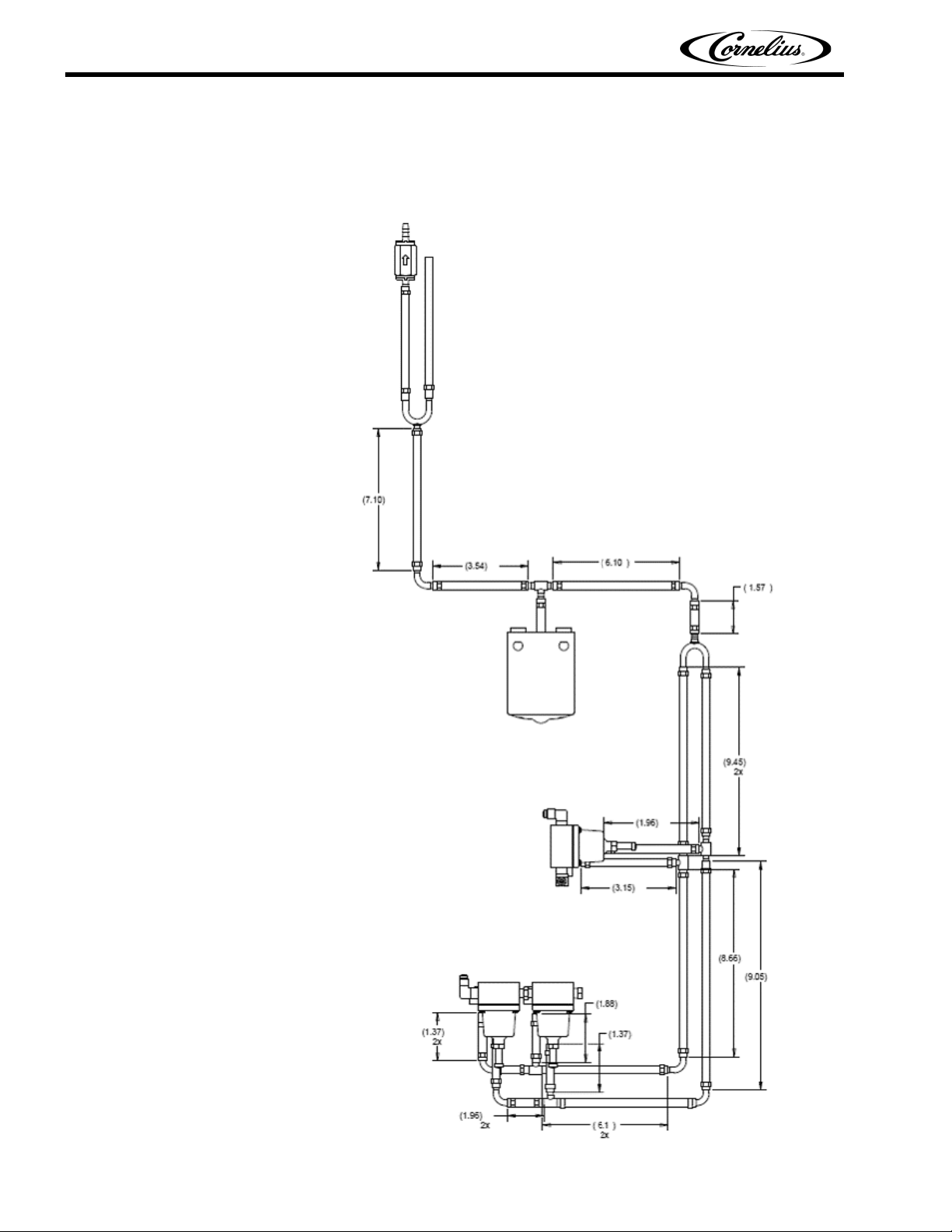
1. Cut the braided hose tube as shown in the reference diagram (Figure 1
or Figure 2).
Figure 1. Approximate Cut Lengths for Tubes, Viper 2 Barrel
Publication Number: 899400001INS - 6 - © 2009, IMI Cornelius Inc.
Page 10

Viper Installation Manual
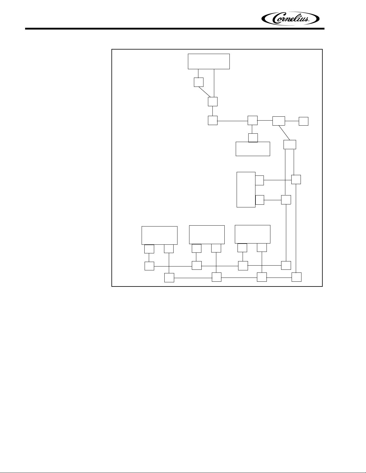
Figure 2. Approximate Cut Lengths for Tubes, Viper 3 Barrel
2. Connect Braided Tubes to Adapter Barbs with Oetiker Clamps and
route the tubes as shown in Figure 3 and Figure 4 for 2-Barrel units
and Figure 5 and Figure 6 for 3-Barrel units, so that the exhaust tube
runs to a naturally ventilated area.
© 2009, IMI Cornelius Inc. - 7 - Publication Number: 899400001INS
Page 11

Viper Installation Manual
Escape to
Atmosphere
C
Y
L T
L
FloJet
A2: Base Ventilation Barb (910705015)
A3: Cone Ventilation Barb (910705016)
T: SS Elbow Connector
L: SS Elbow Connector
Y: 1/4” Y Barb w/1/4” Barb Stem
C: Check Valve
_: Fluid Lines 1/4” Braided Hose Tube)
CO2
Regulator-1
A3
A2
L
L
Figure 3. Representative Plumbing Line Diagram, Viper 2 Barrel
Pump
CO2
Regulator
CO2
Regulator-2
A3
A2
T
T L
A2
A3
L
Y
T
T
L
Publication Number: 899400001INS - 8 - © 2009, IMI Cornelius Inc.
Page 12

Viper Installation Manual
Check Valve
Tube length at this
section depends on
store connections
Y-Connector
FlowJet Pump
Remove filter from the
FlowJet pump and
connect to barb as shown
Regulator Product
Delivery
Regulator Expansion
Tank
Barb, Tee
Barb, Elbow
Figure 4. Representative 3D Plumbing Line Diagram, Viper 2 Barrel
© 2009, IMI Cornelius Inc. - 9 - Publication Number: 899400001INS
Page 13
Viper Installation Manual
Escape to
Atmosphere
C
Y
L T
L
FloJet
A2: Base Ventilation Barb (910705015)
A3: Cone Ventilation Barb (910705016)
T: SS Elbow Connector
L: SS Elbow Connector
Y: 1/4” Y Barb w/1/4” Barb Stem
C: Check Valve
_: Fluid Lines 1/4” Beverage Tube)
CO2
Regulator-1
A3
A2
L
L
Figure 5. Representative Plumbing Line Diagram, Viper 3 Barrel
CO2
Regulator-2
A3
A2
T
T
Pump
CO2
Regulator
CO2
Regulator-3
A3
A2
T
T L
A2
A3
Y
L
L
T
T
L
Publication Number: 899400001INS - 10 - © 2009, IMI Cornelius Inc.
Page 14

Viper Installation Manual
Check Valve
Tube length at this
section depends on
store connections
Y-Connector
FlowJet Pump
Remove filter from the
FlowJet pump and
connect to barb as shown
Regulator Product
Delivery
Regulator Expansion
Tank
Barb, Tee
Figure 6. Representative 3D Plumbing Line Diagram, Viper 3 Barrel
MONTHLY MAINTENANCE SERVICE
The following procedure should be performed on a monthly basis to insure
proper maintenance of the Viper equipment.
• Check all joints for any leakage.
WARNING:Perform the following steps before any service is
attempted.
1. Shut OFF power, water & CO
2. Release system pressure before installation/service.
3. Connect all the braided tubes up to the full length of the adapter barb.
DISCLAIMER
WARNING: Installation of the on-site vent tubing (by others) from IMI
Cornelius equipment to a safe discharge termination or point Failure to comply with the Australian CO
5032-2005: Installation and use of inert gases for beverage
dispensing) in addition to the governing national-state-local
codes may result in serious personal injury or loss of human life.
Barb, Elbow
2 supply before installation/service.
2 Code/Mandate (AS
© 2009, IMI Cornelius Inc. - 11 - Publication Number: 899400001INS
Page 15

Viper Installation Manual
Publication Number: 899400001INS - 12 - © 2009, IMI Cornelius Inc.
Page 16

Page 17

IMI Cornelius Inc.
www.cornelius.com
 Loading...