

Page 1
IMI CORNELIUS INC g One Cornelius Place g Anoka, MN 55303-6234
Telephone (800) 238-3600 Facsimile (800) 535-4231
IMPORTANT:
TO THE INSTALLER.
It is the responsibility of
the Installer to ensure that
the water supply to the
dispensing equipment is
provided with protection
against backflow by an air
gap as defined in
ANSI/ASME A112.1.2-1979;
or an approved vacuum
breaker or other such
method as proved effective
by test.
Installation Manual
I" Series
“REMOTE”
Ice Cube Machine
Water pipe connections
and fixtures directly
connected to a potable
water supply shall be
sized, installed, and
maintained according to
Federal, State, and Local
Codes.
Part No. 166240001
Date of Creation 10/31/94
Revised: 10/8/2003
Control Code A
THIS DOCUMENT CONTAINS IMPORTANT INFORMATION
This Manual must be read and understood before installing or operating this equipment
IMI CORNELIUS INC; 1994–2003
PRINTED IN U.S.A
Page 2

TABLE OF CONTENTS
GENERAL 1. . . . . . . . . . . . . . . . . . . . . . . . . . . . . . . . . . . . . . . . . . . . . . . . . . . . . . . . . . . . . . . .
FREIGHT DAMAGE CLAIMS PROCEDURE 1. . . . . . . . . . . . . . . . . . . . . . . . . . . . . .
INSTALLATION INSTRUCTIONS REMOTE CONDENSERS 2. . . . . . . . . . . . . . . .
REMOTE CONDENSER LOCATION 4. . . . . . . . . . . . . . . . . . . . . . . . . . . . . . . . . . . . .
INSTALLATION INSTRUCTIONS 11. . . . . . . . . . . . . . . . . . . . . . . . . . . . . . . . . . . . . . . . . . .
LOCATION OF EQUIPMENT 11. . . . . . . . . . . . . . . . . . . . . . . . . . . . . . . . . . . . . . . . . . . .
EQUIPMENT SET-UP 11. . . . . . . . . . . . . . . . . . . . . . . . . . . . . . . . . . . . . . . . . . . . . . . . . .
DISPENSER INSTALLATION 11. . . . . . . . . . . . . . . . . . . . . . . . . . . . . . . . . . . . . . . . . . . .
PLUMBING CONNECTIONS 12. . . . . . . . . . . . . . . . . . . . . . . . . . . . . . . . . . . . . . . . . . . .
ELECTRICAL 13. . . . . . . . . . . . . . . . . . . . . . . . . . . . . . . . . . . . . . . . . . . . . . . . . . . . . . . . .
INSTALLATION CHECK POINTS 13. . . . . . . . . . . . . . . . . . . . . . . . . . . . . . . . . . . . . . . .
START-UP AND CHECK OUT 14. . . . . . . . . . . . . . . . . . . . . . . . . . . . . . . . . . . . . . . . . . .
OWNER -OPERATOR 15. . . . . . . . . . . . . . . . . . . . . . . . . . . . . . . . . . . . . . . . . . . . . . . . . . . . . .
CLEANING PROCEDURES 15. . . . . . . . . . . . . . . . . . . . . . . . . . . . . . . . . . . . . . . . . . . .
PREP – CLEANING 15. . . . . . . . . . . . . . . . . . . . . . . . . . . . . . . . . . . . . . . . . . . . . . . . . . . .
CLEANING THE WATER SYSTEM & EVAPORATOR 15. . . . . . . . . . . . . . . . . .
SANITIZING PROCEDURES 16. . . . . . . . . . . . . . . . . . . . . . . . . . . . . . . . . . . . . . . . . . . .
DUMP CYCLE 17. . . . . . . . . . . . . . . . . . . . . . . . . . . . . . . . . . . . . . . . . . . . . . . . . . . . . . . . .
WATER PAN LEVEL SETTINGS 17. . . . . . . . . . . . . . . . . . . . . . . . . . . . . . . . . . . . .
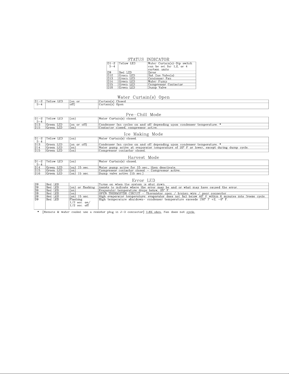
STATUS INDICATOR 19. . . . . . . . . . . . . . . . . . . . . . . . . . . . . . . . . . . . . . . . . . . . . . . . . . .
ADJUSTING BRIDGE THICKNESS 20. . . . . . . . . . . . . . . . . . . . . . . . . . . . . . . . . . . . . .
TOTAL ICE CAPACITY 20. . . . . . . . . . . . . . . . . . . . . . . . . . . . . . . . . . . . . . . . . . . . . . . . .
Page
i
166240001
Page 3

GENERAL
FREIGHT DAMAGE CLAIMS PROCEDURE
The deliverer of your equipment (freight company, distributor or dealer) is responsible for loss or damage of your
shipment. All claims must be filed with the deliverer of your equipment. Please follow the steps below to determine if your shipment is satisfactory or if a claim must be filed:
1. Check the number of products delivered against the number of products listed on the delivery receipt.
Should the totals not match, have the driver note all errors on both copies and both you and the driver sign
and date said notation.
2. Inspect all cartons for visible damage. Open and inspect as required before the driver leaves and have him
or her note any damage on the receipts. All damaged claims must be inspected within 15 days of delivery.
Notify your carrier immediately if concealed damage is found after delivery.
3. Should concealed damage be found when product is unpacked, retain the packing material and the product
and request an inspection from the deliverer.
4. All claims for loss or damage should be filed at once. Delays in filing will reduce the chance of achieving a
satisfactory resolution to the claim.
i
166240001
Page 4
INSTALLATION INSTRUCTIONS REMOTE CONDENSERS
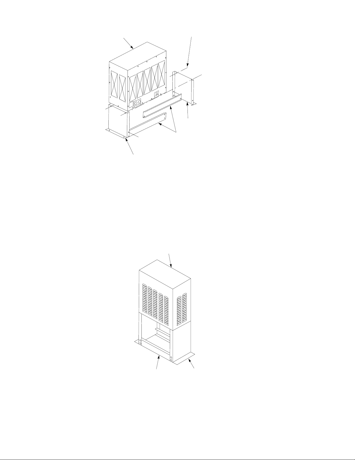
UNIT
LEG
1. Follow the standard installation instructions supplied with cuber. Do not hook cuber into the power source
until the remote condenser and line set installation is complete.
2. Assembly of remote condenser (see drawing):
1/4-20 SCREW
LEG
BRACE
A. Assemble legs to base panel. Install leg supports on legs.
B. Locate the remote condenser in a well ventilated area on the roof away from other refrigeration equip-
ment’s condenser discharge air flow.
C. Use the mounting holes provided to secure the remote condenser to the roof. Seal over heads of bolts
or fasteners with tar or pitch to prevent entrance of moisture.
REMOTE CONDENSER
LEG SUPPORT
LEG
3. Remote condenser electrical hook-up:
A. Connect remote condenser to a power source (208/230VAC, 60 HZ) separate from the cuber. An ex-
ternal disconnect switch must be used.
B. Make sure the electrical connections follow all local and national codes.
C. DO NOT turn condenser on until cuber install and refrigerant line connections are complete!
166240001
ii
Page 5
NOTE:
a. Never wire condenser into cuber section. The condenser is an independent electrical con-
nection.
b. Fan motor will not start until pressure rises to 205 PSIG [14.07 Bars] closing fan cycling
switch.
c. The condenser fan may cycle off during the harvest cycle - This would be normal.
NOTE: Installing an IMI Cornelius remote cuber with other than an IMI Cornelius remote condenser
and line set may be reason to void the cuber warranty.
LIQUID
REFRIGERANT
LINE
DISCHARGE
LINE
CORRECT
4. Each condenser and cuber is connected with two (2) pre-charged lines.
A. The pre-charged lines are ordered separately from the condenser to suit each individual application.
B. The pre-charged line lengths are 20 feet [6.096 meters], 35 feet [10.66 meters] and 55 feet [16.76 me-
ters].
NOTE: *(Pre-charged is defined as a vapor holding charge - not a portion of the system charge.)
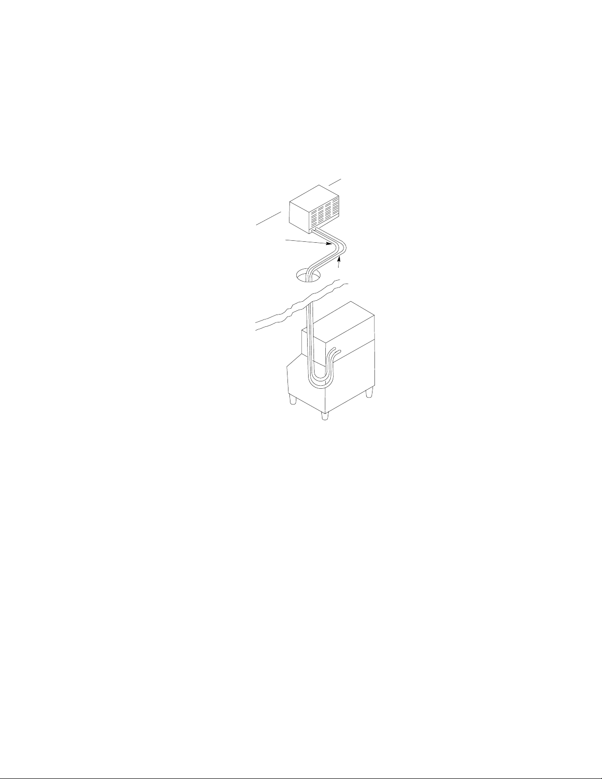
5. Installation of line kits (see drawing) Remove the tubing from the carton. Carefully uncoil the lines so the
tubing doesn’t become kinked, and route lines to cuber and condenser.
6. Keep line set as short as possible. Place a 3 foot service loop behind cuber to allow for rear service should
it ever be required.
REMOTE CONDENSER LOCATION
NOTE: NOTE: Max. line set length for IMI Cornelius cubers is 55 ft. - Do not confuse line
length with calculated line distance.
1. Physical Line Set Length: 55 Ft. Maximum [16.764 meters]
iii
166240001
Page 6
The ice machine compressor must have the proper oil return. Line-set rises, drop, or horizontal runs greater
than the maximum distance allowed will exceed the compressor start-up and pumping design limits, and will
result in poor oil return to the compressor.
Line Set Rise: 35 Ft. Maximum [10.66 meters]
Line Set Drop: 15 Ft. Maximum [4.57 meters]
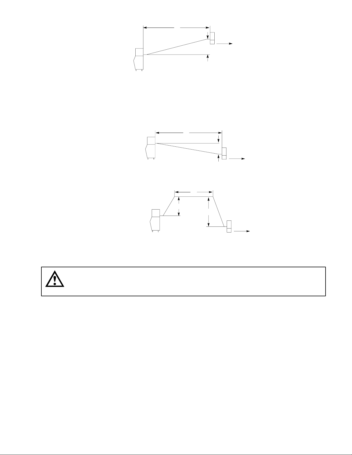
2. Calculated Line Set Distance: 100 Ft. [30.48 meters]
To prevent the combination of rises, drops and horizontal runs exceeding the compressor start-up and pumping
design limit, the following calculations should be made:
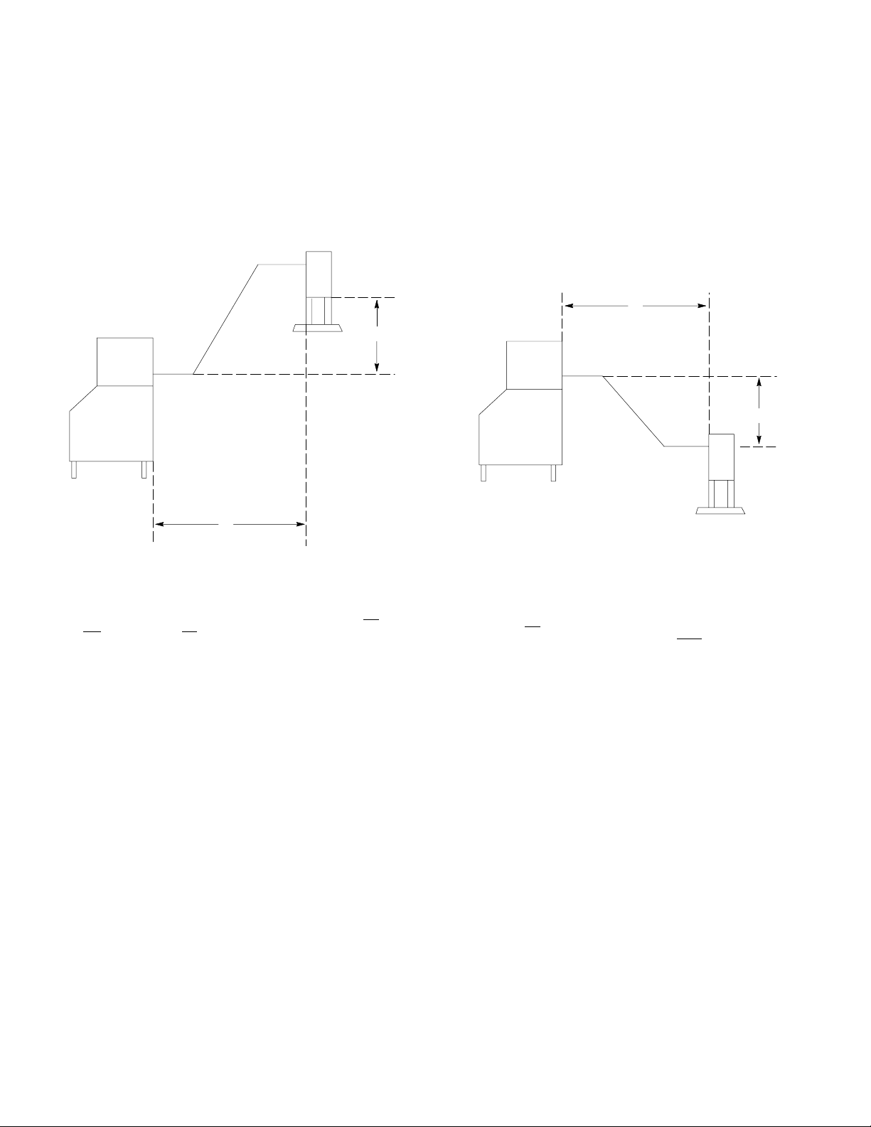
B
A
C
B
A - (RISE)_ CONDENSER HIGHER THEN EVAP. MAX. 35
B – LINE LENGTH 15’: EXAMPLE
B - LINE LENGTH 35’: EXAMPLE
C - (DROP) CONDENSER LOWER THAN EVAP. 15’: MAX.
Maximum Line Set Distance Formula
3. Measured rise x 1.7=Calculated (Rise 35 ft. Max.) [10.66 meters]
4. Measured drop x 6..6=Calculated (Drop 15ft. Max.) [4.57 meters]
5. Measured Horizontal Distance= actual measurement.
6. Total Calculated distance (A+B+C)=Total Calculated Distance (100 ft. Max.) [30.48 meters]
Examples:
a. Insert measured rise (R) into formula and multiply it by 1.7 to get a calculated rise.
example: A condenser located 15 ft. [4.572 meters] above the ice machine has a 25.5 ft. [8.874 meters]
166240001
calculated total (15 ft. x 1.7 = 25.5).
iv
Page 7
H
AIR
FLOW
R
b. Insert measured drop (D) into formula and multiply by 6.6 to get a calculated drop.
example: A condenser located 8 ft. [2.438 meters] below the ice machine has a 52.8 ft. [16.093 meters]
calculated total (8ft. x 6.6 = 52.8 ft.)
COMBIATION OF DROP(S)
WITH HORIZONTAL
H
D
AIR
FLOW
c. Insert measured horizontal distance into formula. No calculation is necessary. (6 ft.) [1.828 meters].
COMBIATION OF RISE AND
DROP(S)WITH HORIZONTAL
H
R
D
AIR
FLOW
d. Add the calculated rise, calculated drop, and horizontal distance together to get the total calculated dis-
tance (25.5 + 52.8 + 6) equals 84.3 ft. [25.694 meters]. If 100 ft. [30.48 meters] total calculated distance
is exceeded, the condenser must be moved to a new location which permits proper equipment operation..
CAUTION: If a line set rise is followed by a line set drop, a second line set rise cannot be
made. or If a line set drop is followed by a line set rise, a second line set drop cannot be
made.
7. Lengthening Or Reducing The Line Set Lengths
In most cases, by routing the line set properly, shortening will not be necessary (refer to illustration). However when shortening or lengthening is required, do so before connecting the line set to the ice machine or
the remote condenser. This prevents the loss of refrigerant from the ice machine or the condenser.
The quick connect fittings on the line sets are equipped with Schrader Valves. Use these valves to recover
any vapor charge from the line set. When lengthening or shortening lines, apply good refrigeration practices and insulate new tubing. Do not change the tube sizes. Evacuate the lines and place approximately 5
oz. of vapor refrigerant charge in each line.
v
166240001
Page 8
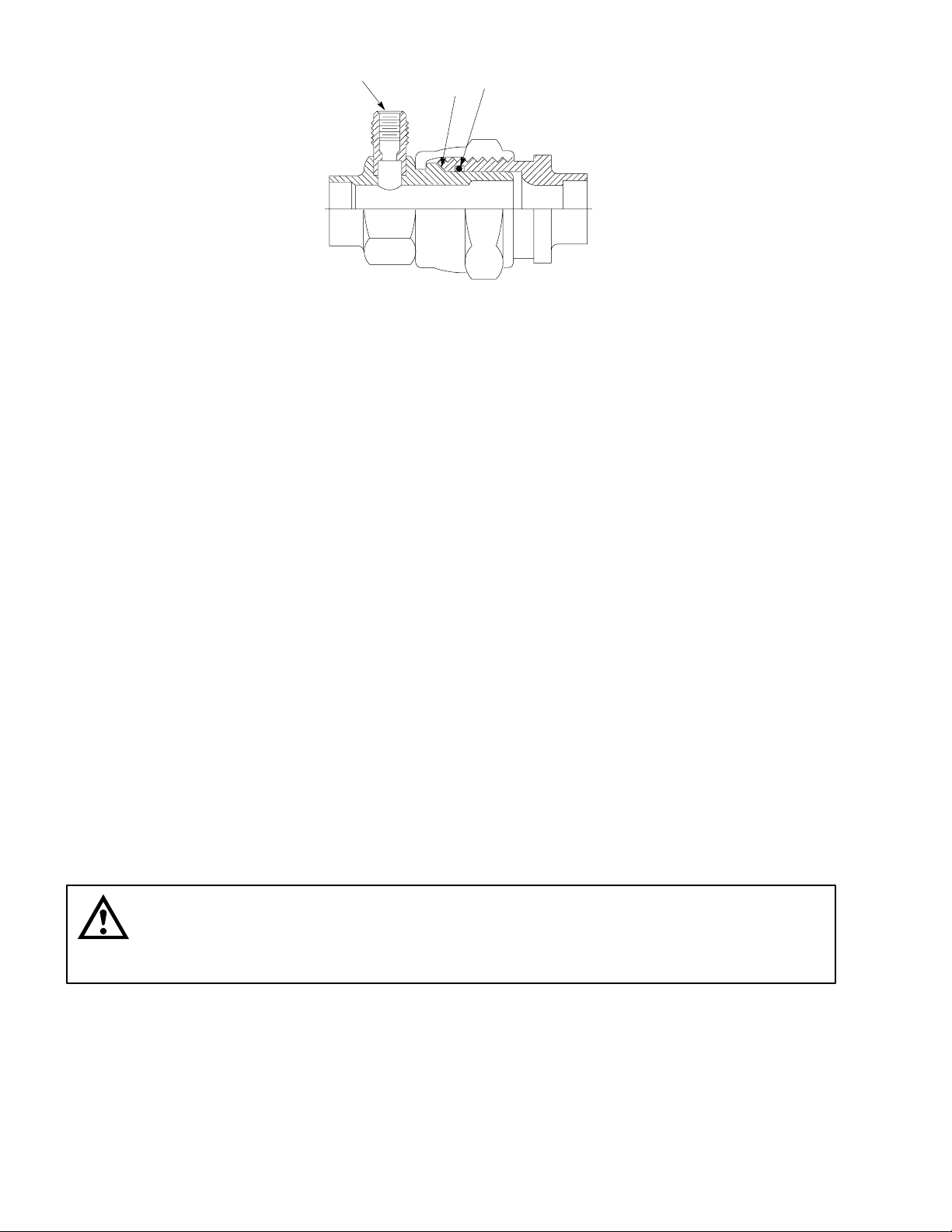
SCHRADER
VA LV E
PARENT
METAL
SEAL
INTERMEDIATE
SEAL
8. Connection of Line Set
A. Remove the plastic caps from the line set, the condenser, and the ice machine.
B. Apply refrigeration oil to the threads on the quick connect couplers before connecting them to the con-
denser.
C. Carefully thread the female fitting onto the condenser or ice machine by hand.
D. Using the proper size wrench, tighten the couplings until they bottom out. Turn an additional 1/4 turn
to ensure proper brass-to-brass seating.
E. Check all fittings for leaks.
9. Final Installation:
A. Remove grill from the right hand side panel of cuber.
B. Turn service port on receiver tank to open position releasing refrigerant to the balance of the system.
C. Leak check line set connections at cuber and condenser.
D. Replace grill.
E. Connect cuber to power source.
F. Make sure electrical connections follow all local and national codes.
10. Start Up:
A. Use standard procedures from cuber installation instructions.
B. After the cuber is running, check the remote condenser and verify that the condenser fan is running.
CAUTION: Once the refrigerant lines are connected, the seal is broken in the fittings. If the
line are removed or loosened from the cuber or remote condenser, the refrigerant charge
will be discharges to the atmosphere. DISCHARGING TO THE ATMOSPHERE IS IN
VIOLATION OF THE CLEAN AIR ACT OF JULY, 1992.
166240001
vi
Page 9

ICE CUBER SPECIFICATION – 60 HERTZ
MODEL IRC630 IRC830
UNIT
Volts 230 230 230 230
Phase 1 1 1 1
Hertz 60 60 60 60
No. Wires 2+ground 2+ground 2+ground 2+ground
MIN. CIRCUIT
Amps 20 20 20 20
MAX FUSE SIZE (HVAC CIRCUIT BREAKER REQUIRED)
Amps 20 20 20 20
REFRIGERANT
Type R404a(HP62) R404a(HP62) R404a(HP62) R404a(HP62)
Weight (oz) 170 170 210 210
Weight (g) 4820 4820 5954 5954
COMPRESSOR
Volts 230 230 230 230
Phase 1 1 1 1
Hertz 60 60 60 60
LRA 69 61 82 96
RLA 8.8 12.5 13.0 13.5
CONDENSER FAN MOTOR (AIR COOLED SYSTEMS ONLY
AIR CIRCULATION FAN MOTOR (WATER-COOLED & REMOTE SYSTEMS ONLY)
Volts 230 230 230 230
Phase 1 1 1 1
Hertz 60 60 60 60
Amps Running 0.36 0.36 0.36 0.36
Watts 6 6 6W 6
WATER PUMP
Volts 230 230 230 230
Phase 1 1 1 1
Hertz 60 60 60 60
Amps Running 0.5 0.5 0.5 0.5
HP 1/30 1/30 1/30 1/30
IRC1030
IRC1030L
IRC1230
vii
166240001
Page 10

ICE CUBER SPECIFICATION – 60 HERTZ
MODEL IRC1448 IRC1448-3PH IRC2448 IRC2448-3PH
UNIT
Volts 230 230 230 230
Phase 1 3 1 3
Hertz 60 60 60 60
No. Wires 2+ground 3+ground 2+ground 3+ground
MIN. CIRCUIT
Amps 25 25 30 25
MAX FUSE SIZE (HVAC CIRCUIT BREAKER REQUIRED)
Amps 25 25 30 25
REFRIGERANT
Type R404a(HP 62) R404a(HP 62) R404a(HP 62) R404a(HP 62)
Weight (oz) 250 250 320 320
Weight (g) 7088 7088 9072 9072
COMPRESSOR
Volts 230 230 230 230
Phase 1 3 1 3
Hertz 60 60 60 60
LRA 95.6 82 125 90
RLA 23.9 10 20 13
CONDENSER FAN MOTOR (AIR COOLED SYSTEMS ONLY
AIR CIRCULATION FAN MOTOR (WATER-COOLED & REMOTE SYSTEMS ONLY)
Volts 230 230 230 230
Phase 1 1 1 1
Hertz 60 60 60 60
Amps Running 0.36 0.36
Watts 6 6W
WATER PUMP
Volts 230 230 230 230
Phase 1 1 1 1
Hertz 60 60 60 60
Amps Running 0.5 0.5 0.77 0.77
HP 1/30 1/30 1/50 1/50
166240001
viii
Page 11

ICE CUBER SPECIFICATION – 50 HERTZ
MODEL
UNIT
Volts 220 220 220 220
Phase 1 1 1 1
Hertz 50 50 50 50
No. Wires 2+ground 2+ground 2+ground 2+ground
MIN. CIRCUIT
Amps 20 20 20 25
MAX FUSE SIZE (HVAC CIRCUIT BREAKER REQUIRED)
Amps 20 20 20 25
REFRIGERANT
Type R404a(HP62) R404a(HP62) R404a(HP62) R404a(HP62)
Weight (oz) 170 170 210 250
Weight (g) 4820 4820 4820 4820
COMPRESSOR
Volts 220 220 220 220
Phase 1 1 1 1
Hertz 50 50 50 50
LRA 53 58 64 75.9
RLA 8 12 12.5 13
CONDENSER FAN MOTOR (AIR COOLED SYSTEMS ONLY
AIR CIRCULATION FAN MOTOR (WATER-COOLED & REMOTE SYSTEMS ONLY)
Volts 220 220 220 220
Phase 1 1 1 1
Hertz 50 50 50 50
Amps Running 0.3 0.3 0.3 0.3
Watts 6 6 6 6
WATER PUMP
Volts 220 220 220 220
Phase 1 1 1 1
Hertz 50 50 50 50
Amps Running 0.5 0.5 0.5 0.5
HP 1/30 1/30 1/30 1/30
IRC630E50
IRC630E50L
IRC830E50
IRC830E50L
IRC1030E50
IRC1030E50L
IRC1230E50
IRC1230E50L
ix
166240001
Page 12

REMOTE CONDENSER SPECIFICATION
MODEL CR800 CR1200 CR1400 CR2400 CR800E50 CR1200E50 CR1400E50
Volts 230 230 230 230 220 220 220
Phase 1 1 1 1 1 1 1
Hertz 60 60 60 60 50 50 50
Amps 1.0 1.0 1.0 3.6 1.1 1.1 1.1
Output, HP 1/6 1/6 1/6 3/4 1/6 1/6 1/6
Max. fuse
size, Amps
(HVAC circuit
breaker required)
20 20 20 20 20 20 20
166240001
x
Page 13

INSTALLATION INSTRUCTIONS
Installation and start-up of the equipment should be performed by the distributor or the dealer’s professional
staff.
LOCATION OF EQUIPMENT
For maximum performance the location should be away from heat sources such as ovens, direct sunlight, hot
air discharge, etc.
To reduce cost of maintenance and loss of efficiency, avoid placing air-cooled equipment in areas where grease,
flour and other airborne contaminants are present. Allow a minimum of 6I (15.24 cm) clearance on all sides and
top for proper air circulation. Restricted air circulation will affect the efficiency and required maintenance of the
product.
IMPORTANT: Never operate your equipment in room temperature below 50_F (10_C) or above 100_F
(38_C). Should the location of your product ever be exposed to freezing temperatures, it must be shut
down and winterized.
EQUIPMENT SET-UP
The following steps refer to the set-up of the ice bin and the cuber:
THREAD LEVELING
LEG INTO BASE
1. Remove the bin from its carton, place it on its back and install the
legs into the bottom of the bin. Bins must be installed on legs or
sealed to the floor with RTV-732 sealant.
2. Set the bin up on its legs. Place the bin in its final location and level
it with the adjustable feet in the legs.
3. Unpack the cuber from its carton, and set in place on the bin and
adjust as required.
4. Remove all internal packing from the cuber.
Bin adapter and condenser air baffles may be required in certain installations.
xi
166240001
Page 14

DISPENSER INSTALLATION
The proper cuber/dispenser installation package should be ordered. This package will include gasket material
and hold-down bracket.
ELECTRICAL SERVICE LINE
MANUAL DISCONNECT SWITCH
SHUT-OFF VALVE
WATER FILTER
STRAIN RELIEF
DUMP VALVE
DRAIN TUBE
AEROQUIP VALVE FITTING
FLOOR DRAIN
BIN DRAIN TUBE
PLUMBING CONNECTIONS
1. All plumbing lines and connections must conform to local and national plumbing codes.
2. Line shut-off valves must be located in supply water lines for cuber and condenser if product is watercooled. Water supply to water-cooled condenser must include a stand-pipe to prevent “water hammer”.
3. Should your local water supply quality require the installation of a water filter system, consult your local distributor or dealer for proper size required.
4. Water supply pressure must not be lower than 20 PSI (1.37 BAR), nor should it exceed 120 PSI (8.16
BAR).
IMPORTANT: Water filters larger then 5 microns do not give proper protection. Water pressures above
80 PSI (5.44 BAR) will destroy the filter.
NOTE: Bin and cuber drain lines must never be connected together and must be vented.
166240001
xii
Page 15

ELECTRICAL
1. All wiring and connections must conform to national and local electrical codes.
2. Wire size and circuit protection must conform to specifications and cuber must be on a separate electrical
circuit.
3. Strain relief connectors must be used at the junctions box of the control box and the cuber.
4. Cuber must be grounded by the control box ground screw or other method for intentional safety grounding
that meets code requirements.
5. A manual disconnect in a convenient location to the cuber must be installed.
INSTALLATION CHECK POINTS
1. Has bin and cuber been leveled and sanitized?
2. Does electrical and plumbing meet code requirements?
3. Check correct operating water level in the water pan.
1-3/4I
3/8I
WATER PAN
RIGHT SIDE VIEW
OPERATING WATER LEVEL 2448
FOUR EVAPORATOR UNIT
OPERATING WATER LEVEL
SINGLE EVAPORATOR UNITS
OPERATING WATER LEVEL
DUAL EVAPORATOR UNITS
4. If water-cooled, are inlet and drain connections to condenser correct to prevent “water hammer”?
5. Are drain lines separate and vented?
6. Is there 6I clearance on all sides and top for proper air circulation?
7. Does the water curtain move freely, and does the float valve shut off incoming water to the water pan?
xiii
166240001
Page 16

START-UP AND CHECK OUT
1. Turn the Cuber’s power switch to the clean (pump only) position.
Power Switch
2. Place the Cuber’s power switch in the on position. After a 2 second
3. Hold the water curtain open for a maximum of 30 seconds; the
4. If all Cuber operation is as stated, allow product to operate and
The water pump only should be operational. Check for an even,
steady flow of water over evaporator top extrusion and down over
evaporator surface. Check that all ports of the water distribution
tube are open for even water discharge. The water pan should refill
and the float should stop the incoming water supply.
Note: Should service be required on the float valve or
strainer, turn the water supply off loosen the float hold down
nut and remove the float and strainer as an assembly for ease
of service.
delay the compressor will start. The condenser fan will operate
when the condenser sensor signals the circuit board its temperature is 100_F (38_C) The water pump will operate when the evaporator cools to 25_F (–3.9_C). Depress the manual harvest switch
(on the circuit board) the fan motor will stop and the water dump
valve will open. In 3 seconds the hot gas solenoid will open and 15
seconds after depressing the manual harvest switch, the water
pump and dump valve will close terminating the dump cycle.
Cuber should shut down. Release the water curtain(s). When the
curtain(s) closes, there will be a 2 second delay, then the compressor will start and the start–up process should begin for the next ice
making mode.
produce one slab of ice, then discard the ice. Allow the Cuber to
continue operation to fill the storage bin.
166240001
xiv
Page 17

OWNER -OPERATOR
The installation is not complete until you are sure the owner-operator understands the cuber operation and his
or her responsibility of preventative maintenance.
Does the owner-operator know:
1. Location of electrical disconnect switch and water shut-off valves?
2. How to start and/or shut down the product, clean and sanitize it?
3. Bin full operation and reset operation of high pressure cutout (water-cooled and remote products only)?
4. How to clean the condenser and fan blade?
5. Whom to call for product information and/or service?
CLEANING PROCEDURES
Approved ice machine cleaners by brand names:
S Lime–A–Way
S Calgon Nickel Safe (green color only)
NOTE: All ice machine cleaners labeled safe for nickel ARE NOT the brand CALGON NICKEL SAFE.
CAUTION: Ice machine cleaners are acidic-based chemicals. Before beginning any
cleaning of the cuber, the ice in the storage bin or dispenser must be removed.
WARNING: When using any chemical, rubber gloves and eye protection should be worn.
PREP – CLEANING
Use full-strength ice machine cleaner on a coarse-surface cloth material (such as terry cloth) and wipe down the
inside wall of the evaporator area, the water pan, the water curtain and evaporator plastic extrusions. If the water distributor tube has heavy scale build–up, remove and soak it in full-strength ice machine cleaner (or exchange the tube and clean the scaled tube at a later date).
Cleaning the Water System & Evaporator
1. Set the switch to Clean and allow any ice on the evaporator to re-
POWER
SWITCH
lease and melt away.
2. Remove all ice from the storage bin.
3. Remove the water curtains, pour 1/2 oz. of ice machine cleaner
down the rear key-slot openings. The cleaner will drain into the water pan.
4. Return the water curtains to their proper operating position.
5. Add 3 oz. for a single evaporator, or 5 oz. for a dual evaporator of
“Calgon Nickel-Safe” or “Lime-A-Away” ice machine cleaner directly into the water pan the float will balance with inlet water. Set
switch to CLEAN, circulate for a maximum of 15 minutes.
xv
166240001
Page 18

6. Depress and hold the dump switch to allow the cleaner to drain away.
7. Fill the water pan with clean fresh water, circulate for approximately 3 minutes. Depress and hold the
DUMP switch and allow the water to drain away. Repeat the procedure 3 times.
8. After third rinse cycle, place product power switch in ice position. Allow Cuber to produce one slab of ice –
DISCARD THE ICE.
9. When the clean cycle is complete, return cuber to normal operating mode.
NOTE: Please Take Note of the Following:
S Ice machines should only be cleaned when needed, not by a timed schedule of every 60 days, etc.
S Should your ice machine require cleaning more than twice a year, consult your distributor or dealer about
proper water treatment.
SANITIZING PROCEDURES
NOTE: To be performed only after cleaning the ice machine:
1. Add 1/4 ounce (7.08 g) sodium hypochlorite solution (common liquid laundry bleach) to the water pan and
allow the pump to circulate the solution for 5 minutes. You may also use a commercial sanitizer such as
Calgon Ice Machine Sanitizer following the directions on the product label.
2. Turn the Cuber power switch off and depress and hold the dump switch to drain the water pan.
3. To sanitize the bin and other surface areas, use 1 ounce of liquid bleach per gallon of water and wipe all
areas with the solution. Or use a commercial sanitizer.
4. Place the Cuber power switch in the ice position. Discard the first batch of ice produced.
5. Cleaning and sanitizing are now complete. Cuber may be returned to normal service.
166240001
xvi
Page 19

DUMP CYCLE
Water Pan Level Settings
1-3/4I
OPERATING WATER LEVEL 2448
FOUR EVAPORATOR UNIT
OPERATING WATER LEVEL
SINGLE EVAPORATOR UNITS
3/8I
WATER PAN
RIGHT SIDE VIEW
OPERATING WATER LEVEL
DUAL EVAPORATOR UNITS
1. With the proper water level in the water pan, start the water pump to circulate the water. Check that the
float will return water level to original setting and stop inlet water.
2. There is a flow washer in the inlet side of the float assembly that will control inlet water pressure from
20/120 PSI (3.4/8.16 Bars). This will prevent float flutter. In low water pressure conditions, 20 PSI (1.37
Bars) or less, the flow washer may have to be removed from the float assembly for proper volume.
FLOW CONTROL WASHER FLAT SIDE UP
3. Push the manual dump switch – allow dump action to drain the water pan. When you release the momentary switch, the pump will stop and the float will return the water level back to its original setting and shut off
the water supply.
4. You have the option of selecting dump cycle intervals of:
S every cycle; (Standard setting from factory)
S every 3rd cycle;
S every 7th cycle.
xvii
166240001
Page 20

Suction Line Sensor
Bridge thickness pot.
S3-1 S3-2
1 OFF OFF Dump Every Harvest (FACTORY SETTING AS RECEIVED)
2 ON OFF Dump Every Third Harvest
3 OFF ON Dump Every Seventh Harvest
ON
S3–2
S3–1
1
OFF
ON
S3–1
2
3
S3–1
S3–1
OFF
6
OFF
OFF
4
5
S3–2
ON
S3–2
ON
S3–2
ON
SW4
OFF
ON
SW4
OFF
ON
SW4
OFF
Dump Cycle Dip Switch
Water Curtain
Dip Switch
Harvest Voltage Set point pins 2
External Error LED
Connection
Condenser Sensor
and 3 Factory setting @ 1.224 V
RD
Error
Dump
GR
Fan
S3–1
On
S3–2
Off
GR
Comp.
On
Curtain
Selection
Switch
Switches
1 2 3
Off
1
2
Bin
3
Micro Processor
YL
YL
Pump
Gear
Gas
GR
GR
GR
YL
4
In
Stack
Out
Com
SINGLE CURTAIN DUAL CURTAIN FOUR CURTAIN
4 Curtain Switch Connected To Any
Bin Connector (J4–J7) (FACTORY
SETTING AS RECEIVED)
5 Curtain Switch Must Be Connected To
Triac
YL
J4 and J5, J6, J7.
Transformer
6 Curtain Switch Must Be Connected
To J4, J5, J6 and J7)
166240001
xviii
Page 21
xix
166240001
Page 22

ADJUSTING BRIDGE THICKNESS
TOP ROW
3/8” - 5/8” DIMPLE
For optimum ice production and maximum cube separation, the ice connecting the individual cubes should be a minimum of 1/8” (.32cm) thick at
the center area of the ice waffle.
CENTER
1/8” BRIDGE
BRIDGE 1/8I (0.32 CM)
It is normal for the ice slab to be slightly thicker at the bottom and taper off
in a slight wedge pattern at the top. The top row of cubes must have a
complete pattern of ice on all four sides and the back wall. Remember,
when you operate the product with the panels off during testing the additional heat at the top of the evaporator will cause thinner ice at the top than
when the panels are in place.
Should a different thickness of the bridge be desired, it will be required to
adjust the ice thickness “POT”, located on the circuit board, as follows:
BOTTOM 2 ROWS
3/16” - 1/4” BRIDGE
1. Thinner Bridge – turn the ice thickness “pot” adjustment screw
CW one full turn. Allow two cycles before determining if addi-
tional adjustments are required.
2. Thicker Bridge – turn the ice thickness “pot” adjusting screw
CCW one full turn. Allow two cycles before determining if addi-
tional adjustments are required.
NOTE: Never judge the thickness of the ice from the first batch of the ice produced – the first cycle is
a balance cycle. Always wait for the second cycle before making any adjustments.
TOTAL ICE CAPACITY
Ice capacity of any ice maker is affected by many operating conditions, such as water and air temperature and
location factors. Please review the capacity tables in this manual for average 24–hour capacity under various
conditions.
NOTE: All printed capacity ratings are 10% except 50 HZ units these products have 12% increase in
cycle time and capacity decrease of approximately 17%.
166240001
xx
Page 23

CORNELIUS LIMITED COMMERCIAL WARRANTY PLAN
TO THE ORIGINAL OWNER OF A CORNELIUS COMMERCIAL CUBE ICEMAKER
This warranty applies to Icemakers installed within the United States, Canada, Mexico and
Puerto Rico only.
For warranty information outside the U.S., Canada, Mexico and Puerto Rico, contact your nearest IMI Cornelius
Sales Office.
PARTS WARRANTY PERIOD
IMI CORNELIUS INC., hereinafter referred to as CORNELIUS, warrants to the original owner of a new CORNELIUS commercial cube ice machine (“Machine”) who buys solely for commercial uses, that the Machine shall be
free from defects in material and/or factory workmanship if properly installed, operated and maintained, under
normal and proper use and service conditions with competent supervision. The parts warranty period is three
years (36 months) from the date of installation or 39 months from the date of shipment by CORNELIUS whichever time period elapses first. With respect to compressor, solid state control board and the evaporator(s), the
warranty period will be five years (60 months) from the date of installation or 63 months from the date of shipment by CORNELIUS whichever time period elapses first. Warranty on evaporator plating limited, subject to the
incoming water conditions and proper cleaning and maintenance. The obligation of CORNELIUS under this warranty is limited to repair or replacement (at the option of CORNELIUS) FOB factory in Mason City, Iowa of the
part (or Parts) of any Machine that is proven defective.
LIMITED LIFETIME WARRANTY
In addition to the above stated parts warranty, Cornelius further warrants the stainless steel cabinet
and frame assembly to the original owner at the original installation site against cracks, rust, or corrosion under normal operating conditions. Models IACS50, AC322 and WC322 are excluded from this
warranty clause.
LIMITED LABOR WARRANTY PERIOD
In addition to the parts warranty, CORNELIUS will pay scheduled straight time labor to repair or replace a defective component when failure occurs within three years (36 months) from the date of installation or 39 months
from the date of shipment by CORNELIUS whichever time period elapses first. Such service is to be performed
by a service agency authorized by CORNELIUS. Time and rate schedules for labor compensation will be published periodically by CORNELIUS. Additional expenses including but not limited to travel time, truck
charges, overtime charges, material cost, accessing or removal of the ice machine, normal prescribed
maintenance cleaning, adjustments, and ice purchases are the responsibility of the original owner.
No parts warranty or labor allowance on the motor compressor assembly will apply when the ice machine’s refrigeration system is modified with a condenser heat reclaim device, or parts and assemblies not provided by
CORNELIUS, unless CORNELIUS provides approval, in writing, for these modifications for specific locations.
The parts warranty shall not apply when destruction or damage is caused by alterations, unauthorized service,
using other than factory authorized replacement parts, risks of transportation, accidents, misuse, damage by
fire, flood or acts of God. No components or assembly from which the serial number or identification number
has been altered or removed will be covered. Any defective parts to be repaired or replaced must be returned to
us through a CORNELIUS distributor/dealer, transportation charges prepaid, and they must be properly sealed
and tagged. The serial and model number of the Machine and the date of original installation of such Machine
must be given. The warranty of repaired or replaced parts will not extend beyond the period of the original warranty. The decision of the CORNELIUS Service Department regarding the warrantability of parts and eligibility
for the labor allowance will be final.
IMI CORNELIUS INC
ONE CORNELIUS PLACE
ANOKA, MINNESOTA 55303–6234
xxi
P/N 163238001
Effective March 1, 1996
Starting with Production
Serial Number Code 96 A
166240001
Page 24

IMI CORNELIUS INC.
CORPORATE HEADQUARTERS:
One Cornelius Place
Anoka, Minnesota 55303-6234
(612) 421-6120
(800) 238-3600
Page 25

 Loading...