

IMG STAGE LINE PPA-100/SW B Instruction Manual
PPA-100/SW Best.-Nr. 24.4190
6-KANAL-KOPFHÖRERVERSTÄRKER
6-CHANNEL HEADPHONE AMPLIFIER
AMPLIFICATEUR CASQUE 6 CANAUX
AMPLIFICATORE A 6 CANALI PER CUFFIA
BEDIENUNGSANLEITUNG • INSTRUCTION MANUAL • MODE D’EMPLOI
ISTRUZIONI PER L’USO • GEBRUIKSAANWIJZING • HANDLEIDING • MANUAL DE INSTRUCCIONES
BRUGSANVISNING • BRUKSANVISNING • KÄYTTÖOHJE
SIG. CLIP
SIG./
CLIP
POWER
MAIN
INPUT
HI
LO
INPUT LEVEL
L
R
100
LEVEL
100
LEVEL
100
LEVEL
100
LEVEL
100
LEVEL
SOLO
MAIN
100
LEVEL
PPA-100/SW
PRO 6-CHANNEL
HEADPHONE AMPLIFIER
LEDS:
GREEN–SIGNAL
RED–PEAK
1
CH
2
CH
3
CH
4
CH
5
CH
6
CH
SOLO
MAIN
SOLO
MAIN
SOLO
MAIN
SOLO
MAIN
SOLO
MAIN

2
Bevor Sie einschalten ...
Wir wünschen Ihnen viel Spaß mit Ihrem neuen Gerät von
„img Stage Line“. Dabei soll Ihnen diese Bedienungsanleitung helfen, alle Funktionsmöglichkeiten kennen zu lernen. Die Beachtung der Anleitung vermeidet außerdem
Fehlbedienungen und schützt Sie und Ihr Gerät vor eventuellen Schäden durch unsachgemäßen Gebrauch.
Den deutschen Text finden Sie auf den Seiten 4 –5.
Before you switch on ...
We wish you much pleasure with your new “img Stage
Line” unit. With these operating instructions you will be
able to get to know all functions of the unit. By following
these instructions false operations will be avoided, and
possible damage to yourself and your unit due to improper use will be prevented.
You will find the English text on the pages 4– 5.
D
A
CH
GB
Voordat u inschakelt ...
Wij wensen u veel plezier met uw nieuw toestel van “img
Stage Line”. Met behulp van bijgaande gebruiksaanwijzing kunt u alle functiemogelijkheden leren kennen.
Door deze instructies op te volgen zal een slechte werking vermeden worden, en zal een eventueel letsel aan
uzelf en schade aan uw toestel tengevolge van onzorgvuldig gebruik worden voorkomen.
U vindt de nederlandstalige tekst op de pagina’s 8– 9.
Antes de cualquier instalación
Tenemos de agradecerle el haber adquirido un aparato
“img Stage Line” y le deseamos un agradable uso. Este
manual quiere ayudarle a conocer las multiples facetas
de este aparato. La observación de las instrucciones
evita operaciones erróneas y protege Vd. y vuestro aparato contra todo daño posible por cualquier uso inadecuado.
La versión española se encuentra en las páginas 8– 9.
NL
B
E
Inden De tænder for apparatet ...
Vi ønsker Dem god fornøjelse med Deres nye “img
Stage Line” apparat. Denne brugsanvisning giver mulighed for at lære alle apparatets funktioner at kende. Følg
vejledningen for at undgå forkert betjening og for at
beskytte Dem og Deres apparat mod skade på grund af
forkert brug.
Den danske tekst finder De på side 10– 11.
Förskrift
Vi önskar dig mycket nöje med din nya “img Stage Line”
enheten. Om du först läser instruktionerna kommer du
att få glädje av enheten under lång tid. Kunskap om alla
funktioner kan bespara dig mycket besvär med enheten
i framtiden.
Du finner den svenska texten på sidan 10– 11.
DK S
Ennen virran kytkemistä ...
Toivomme, että uusi “img Stage Line”-laitteesi tuo sinulle
paljon iloa ja hyötyä. Tämä käyttöohje esittää sinulle
kaikki uuden laitteesi toiminnot. Seuraamalla sitä vältät
virhetoiminnot ja niistä johtuvat mahdolliset vahingot
sinulle tai laitteellesi.
Löydät suomenkieliset käyttöohjeet sivuilta 12.
FIN
Avant toute mise en service ...
Nous vous remercions d’avoir choisi un appareil “img
Stage Line” et vous souhaitons beaucoup de plaisir à
l’utiliser. Cette notice a pour objectif de vous aider à
mieux connaître les multiples facettes de l’appareil. En
outre, en respectant les conseils donnés, vous éviterez
toute mauvaise manipulation de sorte que vous-même et
votre appareil soient protégés de tout dommage.
La version française se trouve pages 6– 7.
Prima di accendere ...
Vi auguriamo buon divertimento con il Vostro nuovo
apparecchio “img Stage Line”. Le istruzioni per l’uso Vi
possono aiutare a conoscere tutte le possibili funzioni. E
rispettando quanto spiegato nelle istruzioni, evitate di
commettere degli errori, e così proteggete Voi stessi, ma
anche l’apparecchio, da eventuali rischi per uso improprio.
Il testo italiano lo potete trovare alle pagine 6– 7.
F
B
CH
I
wwwwww..iimmggssttaaggeelliinnee..ccoomm
3
POWER
MAIN
INPUT
HI
LO
INPUT LEVEL
L
R
100
LEVEL
PPA-100/SW
PRO 6-CHANNEL
HEADPHONE AMPLIFIER
1
CH
2
CH
3
CH
4
CH
5
CH
6
CH
SOLO
MAIN
100
LEVEL
SOLO
MAIN
100
LEVEL
SOLO
MAIN
100
LEVEL
SOLO
MAIN
100
LEVEL
SOLO
MAIN
100
LEVEL
SOLO
MAIN
LEDS:
GREEN–SIGNAL
RED–PEAK
CH 6
MAIN INPUT SOLO INPUT
CH 5 CH 4 CH 3 CH 2 CH 1
230V~/50Hz
MAINS
R
L
12 34 56 7 8 9
10 11 12 13
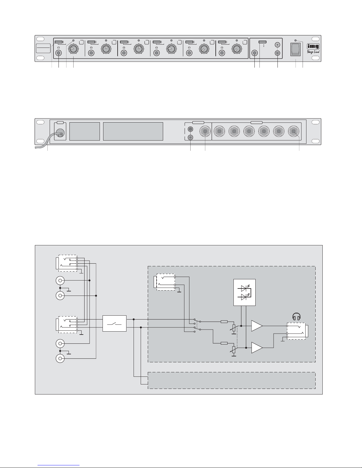
➀
CHANNEL 1
INPUT LEVEL
-
20 dB
L
R
L
R
SOLO
INPUT
MAIN / SOLO
PHONES
OUTPUT
CHANNELS 2 ... 6
MAIN INPUT
REAR
MAIN INPUT
FRONT
SIGNAL
PEAK
➁
➂
Blockschaltbild/ Block diagram
Bitte klappen Sie die Seite 3 heraus. Sie sehen
dann immer die beschriebenen Bedienelemente
und Anschlüsse.
1 Übersicht der Bedienelemente und
Anschlüsse
(die Kanäle 1 bis 6 sind identisch)
1.1 Frontseite
1 Umschalter SOLO/MAIN für den jeweiligen
Kopfhörerausgang (2)
Taste nicht gedrückt:
das Signal des entsprechenden Einzeleingangs SOLO INPUT (13) ist im Kopfhörer zu
hören
Taste gedrückt:
das Signal des Haupteingangs MAIN INPUT
(5, 7, 11 bzw. 12) ist im Kopfhörer zu hören
2
6,3-mm-Klinkenbuchse für den Kopfhörer
3 Signal-LED
leuchtet grün:
ab einer bestimmten Lautstärke am Kopfhörerausgang (2)
leuchtet rot:
bei Übersteuerungen; Regler LEVEL (4) entsprechend zurückdrehen
4 Lautstärkeregler LEVEL
5 Haupteingang MAIN INPUT über 6,3-mm-Klin-
kenbuchse auf der Frontseite;
beim Anschluss dieser Buchse werden die Signale der anderen Buchsen MAIN INPUT (7, 11,
12) abgeschaltet
6 Pegelschalter INPUT LEVEL für den Hauptein-
gang MAIN INPUT
Taste nicht gedrückt:
das Eingangssignal wird nicht abgeschwächt
Taste gedrückt:
das Eingangssignal wird um 20 dB auf
1
/10
abgeschwächt
7 Haupteingang MAIN INPUT über Cinch-Buch-
sen; parallelgeschaltet mit den Cinch-Buch-
sen (11) auf der Rückseite;
beim Anschluss einer der Klinkenbuchsen (5 oder
12) werden die Cinch-Buchsen abgeschaltet
8 Ein-/Ausschalter POWER
9 Betriebsanzeige
1.2 Rückseite
10 Netzkabel zum Anschluss an eine Steckdose
(230V~/50Hz)
11 Haupteingang MAIN INPUT über Cinch-Buch-
sen; parallelgeschaltet mit den Cinch-Buchsen
(7) auf der Frontseite;
beim Anschluss einer der Klinkenbuchsen (5 oder
12) werden die Cinch-Buchsen abgeschaltet
12 Haupteingang MAIN INPUT über 6,3-mm-Klin-
kenbuchse auf der Rückseite;
beim Anschluss dieser Buchse werden die Signale der Cinch-Buchsen (7+11) abgeschaltet;
andererseits wird beim Anschluss der Klinkenbuchse MAIN INPUT (5) auf der Frontseite diese
Buchse abgeschaltet
13 Einzeleingang SOLO INPUT für jeden Kanal
getrennt
2 Hinweise für den sicheren Gebrauch
Dieses Gerät entspricht der Richtlinie für elektromagnetische Verträglichkeit 89/ 336/ EWG und der
Niederspannungsrichtlinie 73/ 23/EWG.
Beachten Sie auch unbedingt die folgenden Punkte:
●
Verwenden Sie das Gerät nur im Innenbereich.
Schützen Sie es vor Tropf- und Spritzwasser,
hoher Luftfeuchtigkeit und Hitze (zulässiger Einsatztemperaturbereich 0– 40 °C).
●
Stellen Sie keine mit Flüssigkeit gefüllten Gefäße,
z.B. Trinkgläser, auf das Gerät.
●
Nehmen Sie das Gerät nicht in Betrieb bzw. ziehen Sie sofort den Netzstecker, wenn:
1. sichtbare Schäden am Gerät oder an der Netzanschlussleitung vorhanden sind,
2. nach einem Sturz oder Ähnlichem der Verdacht
auf einen Defekt besteht,
3. Funktionsstörungen auftreten.
Lassen Sie das Gerät in jedem Fall in einer Fachwerkstatt reparieren.
●
Eine beschädigte Netzanschlussleitung darf nur
durch den Hersteller oder durch eine autorisierte
Fachwerkstatt ersetzt werden.
●
Ziehen Sie den Netzstecker nie am Kabel aus der
Steckdose, fassen Sie immer am Stecker an.
●
Für die Reinigung nur ein trockenes, weiches
Tuch verwenden, auf keinen Fall Chemikalien
oder Wasser.
●
Wird das Gerät zweckentfremdet, falsch angeschlossen bzw. bedient oder nicht fachgerecht repariert, kann keine Haftung für daraus resultierende Sach- oder Personenschäden und keine
Garantie für das Gerät übernommen werden.
3 Einsatzmöglichkeiten
Der PPA-100/ SW ist ein 6-Kanal-Kopfhörerverstärker in Stereoausführung. Mit ihm können Audiosignale mit Line-Pegel (z. B. von CD-Spielern, TapeDecks, Mischpulten) für die Wiedergabe über bis zu
sechs Kopfhörer verstärkt werden. Auf jeden Kanal
kann ein anderes Eingangssignal über die Eingänge
SOLO INPUT gegeben werden. Ein weiteres Eingangssignal am Eingang MAIN INPUT lässt sich auf
mehrere Kanäle verteilen.
Soll das Gerät endgültig aus dem Betrieb genommen werden, übergeben Sie
es zur umweltgerechten Entsorgung
einem örtlichen Recyclingbetrieb.
Achtung! Das Gerät wird mit lebensgefährlicher
Netzspannung (230 V~) versorgt. Nehmen Sie deshalb niemals selbst Eingriffe am Gerät vor. Durch unsachgemäßes Vorgehen besteht die Gefahr
eines elektrischen Schlages. Außerdem
erlischt beim Öffnen des Gerätes jeglicher Garantieanspruch.
Please unfold page 3. Then you can always see the
operating elements and connections described.
1 Operating Elements and Connections
(channels 1 to 6 are identical)
1.1 Front panel
1 Selector switch SOLO/ MAIN for the respective
headphone output (2)
button not pressed:
the signal of the corresponding SOLO INPUT
(13) can be heard in the headphones
button pressed:
the signal of the MAIN INPUT (5, 7, 1 1, or 12)
can be heard in the headphones
2 6.3mm jack for the headphones
3 Signal LED
lights green:
starting from a certain volume at the headphone output (2)
lights red:
in case of overload; turn back control LEVEL
(4) correspondingly
4 Volume control LEVEL
5 MAIN INPUT via 6.3mm jack at the front panel;
when connecting this jack the signals of the other
MAIN INPUT jacks (7, 11, 12) are switched off
6 Level switch INPUT LEVELfor the MAIN INPUT
button not pressed:
the input signal is not attenuated
button pressed:
the input signal is attenuated by 20dB to
1
/10
7 MAIN INPUT via phono jacks; connected in par-
allel with the phono jacks (11) at the rear panel;
when connecting one of the 6.3 mm jacks (5 or
12), the phono jacks are switched off
8 POWER switch
9 POWER LED
1.2 Rear panel
10 Mains cable for the connection to a mains socket
(230V~/50Hz)
11 MAIN INPUT via phono jacks; connected in par-
allel with the phono jacks (7) at the front panel;
when connecting one of the 6.3 mm jacks (5 or
12), the phono jacks are switched off
12 MAIN INPUT via 6.3mm jack at the rear panel;
when connecting this jack, the signals of the
phono jacks (7+11) are switched off;
on the other hand this jack is switched off when
connecting the 6.3mm jack of the MAIN INPUT
(5) at the front panel
13 Separate SOLO INPUT for each channel
2 Safety Notes
This unit corresponds to the directive for electromagnetic compatibility 89/ 336 /EEC and to the low
voltage directive 73/23/EEC.
Please observe the following items in any case:
●
The unit is suitable for indoor use only. Protect it
against dripping water and splash water, high
humidity, and heat (admissible ambient temperature range 0– 40°C).
●
Do not place any vessels filled with liquid, e. g.
drinking glasses, on the unit.
●
Do not operate the unit or immediately disconnect
the plug from the mains socket
1. if there is visible damage to the unit or to the
mains cable.
2. if a defect might have occurred after the unit
was dropped or suffered a similar accident.
3. if malfunctions occur.
In any case the unit must be repaired by authorized personnel.
●
A damaged mains cable may only be repaired by
the manufacturer or by authorized skilled personnel.
●
Never pull the mains cable to disconnect the mains
plug from the mains socket, always seize the plug.
●
Use a dry dust cloth only for cleaning, by no
means chemicals or water.
●
No guarantee claims for the unit and no liability for
any resulting personal damage or material damage will be accepted if the unit is used for other
purposes than originally intended, if it is not correctly connected, operated, or not repaired in an
expert way.
●
Important for U.K. Customers!
The wires in this mains lead are coloured in
accordance with the following code:
blue = neutral
brown = live
As the colours of the wires in the mains lead of this
appliance may not correspond with the coloured
markings identifying the terminals in your plug,
proceed as follows:
1. The wire which is coloured blue must be
connected to the terminal in the plug which is
marked with the letter N or coloured black.
2. The wire which is coloured brown must be
connected to the terminal which is marked with
the letter L or coloured red.
3 Applications
The
PPA-100/SW
is a 6-channel headphone amplifier in stereo version. This unit enables to amplify
audio signals with line level (e.g. of CD players, tape
If the unit is to be put out of operation
definitively, take it to a local recycling
plant for disposal which is not harmful to
the environment.
Attention!The unit is supplied with hazardous
mains voltage (230 V~). Leave servicing to authorized personnel only. Inexpert handling may cause an electric
shock hazard. Furthermore, any guarantee claim will expire if the unit has
been opened.
4
GB
D
A
CH
 Loading...