

IMG STAGE LINE PMX-700DSP Instruction Manual
BEDIENUNGSANLEITUNG • INSTRUCTION MANUAL
MODE D’EMPLOI • ISTRUZIONI PER L’USO • GEBRUIKSAANWIJZING • MANUAL DE INSTRUCCIONES
INSTRUKCJA OBSLUGI • SIKKERHEDSOPLYSNINGER • SÄKERHETSFÖRESKRIFTER • TURVALLISUUDESTA
STEREO POWER MIXER
TABLE DE MIXAGE STÉRÉO AMPLIFIÉE
MIXER STEREO DI POTENZA
PMX-700DSP Best.-Nr. 20.1930

2
wwwwww..iimmggssttaaggeelliinnee..ccoomm
Bevor Sie einschalten ...
Wir wünschen Ihnen viel Spaß mit Ihrem neuen Gerät
von „img Stage Line“. Dabei soll Ihnen diese Bedienungsanleitung helfen, alle Funktionsmöglichkeiten kennen zu lernen. Die Beachtung der Anleitung vermeidet
außerdem Fehlbedienungen und schützt Sie und Ihr
Gerät vor eventuellen Schäden durch unsachgemäßen
Gebrauch.
Den deutschen Text finden Sie auf den Seiten 4– 16.
Before you switch on ...
We wish you much pleasure with your new unit by “img
Stage Line”. With these operating instructions you will be
able to get to know all functions of the unit. By following
these instructions false operations will be avoided, and
possible damage to you and your unit due to improper
use will be prevented.
You will find the English text on the pages 4 –16.
D
A
CH
GB
Avant toute mise en service ...
Nous vous remercions d’avoir choisi un appareil “img
Stage Line” et vous souhaitons beaucoup de plaisir à
l’utiliser. Cette notice a pour objectif de vous aider à
mieux connaître les multiples facettes de l’appareil et à
vous éviter toute mauvaise manipulation.
La version française se trouve pages 17– 29.
Prima di accendere ...
Vi auguriamo buon divertimento con il Vostro nuovo apparecchio “img Stage Line”. Le istruzioni per l’uso Vi possono aiutare a conoscere tutte le possibili funzioni. E
rispettando quanto spiegato nelle istruzioni, evitate di
commettere degli errori, e così proteggete Voi stessi, ma
anche l’apparecchio, da eventuali rischi per uso improprio.
Il testo italiano lo potete trovare alle pagine 17– 29.
F
B
CH
I
Voordat u inschakelt ...
Wij wensen u veel plezier met uw nieuw toestel van “img
Stage Line”. Met behulp van bijgaande gebruiksaanwijzing zal u alle functiemogelijkheden leren kennen.
Door deze instructies op te volgen zal een slechte werking vermeden worden, en zal een eventueel letsel aan
uzelf en schade aan uw toestel tengevolge van onzorgvuldig gebruik worden voorkomen.
U vindt de nederlandstalige tekst op de pagina’s 30– 42.
Antes de cualquier instalación ...
Tenemos de agradecerle el haber adquirido un aparato
“img Stage Line” y le deseamos un agradable uso. Este
manual quiere ayudarle a conocer las multiples facetas
de este aparato. La observación de las instrucciones
evita operaciones erróneas y protege Vd. y vuestro aparato contra todo daño posible por cualquier uso inadecuado.
La versión española se encuentra en las páginas 30– 42.
NL
B
E
Przed uruchomieniem …
Życzymy zadowolenia z nowego produktu “ img Stage
Line”. Dzięki tej instrukcji obsługi będą państwo w stanie
poznać wszystkie funkcje tego urządzenia. Stosując się
do instrukcji unikną państwo błędów i ewentualnego
uszkodzenia urządzenia na skutek nieprawidłowego
użytkowania.
Tekst polski znajduje się na stronach 43 –49.
Inden De tænder for apparatet ...
Vi ønsker Dem god fornøjelse med Deres nye “img
Stage Line” apparat. Læs oplysningerne for en sikker
brug af apparatet før ibrugtagning. Følg sikkerhedsoplysningerne for at undgå forkert betjening og for at beskytte Dem og Deres apparat mod skade på grund af forkert brug.
Sikkerhedsoplysningerne finder De på side 52.
PL DK
Förskrift
Vi önskar dig mycket nöje med din nya enhet från “img
Stage Line”. Läs gärna säkerhetsinstruktionerna innan
du använder enheten. Genom att följa säkerhetsinstruktionerna kan många problem undvikas, vilket annars kan
skada enheten.
Du finner säkerhetsinstruktionerna på sidan 52.
S
FIN
Ennen virran kytkemistä ...
Toivomme, että uusi “img Stage Line”-laitteesi tuo sinulle
paljon iloa ja hyötyä. Ole hyvä ja lue käyttöohjeet ennen
laitteen käyttöönottoa. Luettuasi käyttöohjeet voit käyttää laitetta turvallisesti ja vältyt laitteen väärinkäytöltä.
Käyttöohjeet löydät sivulta 52.
3
∞
–10
–5
0dB
+5
+10
–20
1
PEAK
L-R
GROUP
PFL
+15–15
0
+15–15
0
+15–15
0
MIC
LINE
INSERT
TIP: SEND
RING: RTN
1
GAIN
10 60dB
40
3020
350
450
1k
1k8
2k5
5k
6kHz
HI
12kHz
MID
LO
60Hz
10
EFF
0
10
AUX
0
10FB0
R
PAN
L
∞
–10
–5
0dB
+5
+10
–20
M1
GAIN
MIC
10 50dB
40
3020
HI
12kHz
MID
2.5kHz
LO
45Hz
10
EFF
0
10
AUX
0
10FB0
R
BAL
L
PEAK
L-R
GROUP
PFL
-10 +20dB
+100
GAIN
LINE
+5
+15–15
0
+15–15
0
+15–15
0
MIC
LINE
LEFT/
MONO
RIGHT
M1
PGM EDIT F/S
EFFECT
TYPE
DATA
ENTRY
HELP
AUX
MUTE
DELAY
PARAMETER
PGM CHECK
USER PRESETS
1234
ON
PEAKONWARM
BRIGHT
EFFECT EFFECT EQ REGEN
MAX
MIN
EFFECT TO FB
MAX
MIN
LEFT RIGHT
+8
6
4
2
0dB
3
6
9
12
-20
PFL
L/R FBSLIT
STANDBY
900W
+12
9
6
3
0dB
3
6
9
-12
LEFTL/R
+12
9
6
3
0dB
3
6
9
-12
RIGHT
FB
SPLIT
GRAPHIC EQ
ASSIGN
50Hz 150 Hz 330Hz 1k 2k5 5k 10k
AUX INPUT
L/MONO
R
TAPE PLAY
TAPE REC
LR
AMP CLIP
∞
–5
0dB
+5
–10
–15
–20
∞
–5
0dB
+5
–10
–15
–20
∞
–5
0dB
+5
–10
–15
–20
∞
–5
0dB
+5
–10
–15
–20
GROUP FB EFFECT LEFT RIGHT
PHANTOM
POWER
+48V
L-R
GROUP
AMP
10
AUX
IN
LEVEL
0
10
AUX
IN
TO
FB
0
NORM
AMP
LEVEL
10
METER/PHONES
SELECT
0
L-R
FB
PHONES
PMX-700DSP
115 BPM – 521 mS
L-R
SPLIT
FULL RANGE INTERNAL HP/SUB OUT
ACTIVE CROSSOVER NETWORK 150Hz
2
3
4
5
6
7
12
8
11
13
14
9
10
15
17
18
19
20
21
24
26
28
30
25
23
41
27
29
31
33
32
34
35
36
37
38
42
40
43
44
45
46
47
48
49
51
50
52
53
54
55
56
57
58
59
1
16
39
RECALL
22
60 61 62 63 64 65 66 67 68
230V~/50Hz
POWER
AUX
LEFT RIGHT
RL
SPLIT
FB L/R
SPEAKER OUTPUT
SPLIT
FB L/R
RL
LINE OUT/SUB OUTFB
1+
1–
2+
2–
–
+
SPEAKON
MIC INPUTS
12
3
GND+
–
LINE INPUTS / OUTPUTS
WARNING:
AIR VENTS ON FRONT AND REAR MUST NOT BE OBSTRUCTED
SIGNALGND
UNBALANCED
+GND
BALANCED
–
PMX-700DSP
900W POWERED MIXER
FOOTSWITCH
GND
SENDGND
RTN
MONO CH
AMP
IN
MIXER
OUT
T6.3AL
AMP INSERT
PGM EDIT F/S
EFFECT
TYPE
DATA
ENTRY
HELP
AUX
MUTE
DELAY
PARAMETER
PGM CHECK
USER PRESETS
1234
ON
PEAKONWARM
BRIGHT
EFFECT EFFECT EQ REGEN
MAX
MIN
EFFECT TO FB
MAX
MIN
LEFT RIGHT
+8
6
4
2
0dB
3
6
9
12
-20
PFL
L/R FBSLIT
STANDBY
900W
+12
9
6
3
0dB
3
6
9
-12
LEFTL/R
+12
9
6
3
0dB
3
6
9
-12
RIGHT
FB
SPLIT
GRAPHIC EQ
ASSIGN
50Hz 150Hz 330Hz 1k 2k5 5k 10k
AUX INPUT
L/MONO
R
TAPE PLAY
TAPE REC
LR
AMP CLIP
∞
–5
0dB
+5
–10
–15
–20
∞
–5
0dB
+5
–10
–15
–20
∞
–5
0dB
+5
–10
–15
–20
∞
–5
0dB
+5
–10
–15
–20
∞
–10
–5
0dB
+5
+10
–20
∞
–10
–5
0dB
+5
+10
–20
∞
–10
–5
0dB
+5
+10
–20
∞
–10
–5
0dB
+5
+10
–20
∞
–10
–5
0dB
+5
+10
–20
∞
–10
–5
0dB
+5
+10
–20
∞
–10
–5
0dB
+5
+10
–20
∞
–10
–5
0dB
+5
+10
–20
GROUP FB EFFECT LEFT RIGHT1 23456M1M2
10 CHANNEL
PRO AUDIO MIXER
ULTRA LOW NOISE
DESIGN
900WATTS
POWER AMPLIFIER
PEAK
L-R
GROUP
PFL
GAIN
MIC
10 50dB
40
3020
HI
12kHz
MID
2.5kHz
LO
45Hz
10
EFF
0
10
AUX
0
10FB0
R
BAL
L
PEAK
L-R
GROUP
PFL
-10 +20dB
+100
GAIN
LINE
+5
GAIN
MIC
10 50dB
40
3020
HI
12kHz
MID
2.5kHz
LO
45Hz
10
EFF
0
10
AUX
0
10FB0
R
BAL
L
PEAK
L-R
GROUP
PFL
-10 +20dB
+100
GAIN
LINE
+5
PHANTOM
POWER
+48V
L-R
GROUP
AMP
10
AUX
IN
LEVEL
0
10
AUX
IN
TO
FB
0
NORM
AMP
LEVEL
10
METER/PHONES
SELECT
0
L-R
FB
PHONES
PMX-700DSP
115 BPM – 521 mS
+15–15
0
+15–15
0
+15–15
0
+15–15
0
+15–15
0
+15–15
0
+15–15
0
+15–15
0
+15–15
0
+15–15
0
+15–15
0
+15–15
0
+15–15
0
+15–15
0
+15–15
0
+15–15
0
+15–15
0
+15–15
0
+15–15
0
+15–15
0
+15–15
0
+15–15
0
+15–150+15–15
0
MIC
LINE
INSERT
TIP: SEND
RING: RTN
1
MIC
LINE
INSERT
TIP: SEND
RING: RTN
2
MIC
LINE
INSERT
TIP: SEND
RING: RTN
3
MIC
LINE
INSERT
TIP: SEND
RING: RTN
4
MIC
LINE
INSERT
TIP: SEND
RING: RTN
5
MIC
LINE
INSERT
TIP: SEND
RING: RTN
6
MIC MIC
LINE
LEFT/
MONO
RIGHT
LINE
LEFT/
MONO
RIGHT
M1 M2
L-R
SPLIT
FULL RANGE INTERNAL HP/SUB OUT
ACTIVE CROSSOVER NETWORK 150Hz
GAIN
10 60dB
40
3020
350
450
1k
1k8
2k5
5k
6kHz
HI
12kHz
MID
LO
60Hz
10
EFF
0
10
AUX
0
10FB0
R
PAN
L
GAIN
10 60dB
40
3020
350
450
1k
1k8
2k5
5k
6kHz
HI
12kHz
MID
LO
60Hz
10
EFF
0
10
AUX
0
10FB0
R
PAN
L
PEAK
L-R
GROUP
PFL
GAIN
10 60dB
40
3020
350
450
1k
1k8
2k5
5k
6kHz
HI
12kHz
MID
LO
60Hz
10
EFF
0
10
AUX
0
10FB0
R
PAN
L
PEAK
L-R
GROUP
PFL
GAIN
10 60dB
40
3020
350
450
1k
1k8
2k5
5k
6kHz
HI
12kHz
MID
LO
60Hz
10
EFF
0
10
AUX
0
10FB0
R
PAN
L
PEAK
L-R
GROUP
PFL
GAIN
10 60dB
40
3020
350
450
1k
1k8
2k5
5k
6kHz
HI
12kHz
MID
LO
60Hz
10
EFF
0
10
AUX
0
10FB0
R
PAN
L
PEAK
L-R
GROUP
PFL
GAIN
10 60dB
40
3020
350
450
1k
1k8
2k5
5k
6kHz
HI
12kHz
MID
LO
60Hz
10
EFF
0
10
AUX
0
10FB0
R
PAN
L
PEAK
L-R
GROUP
PFL
RECALL
➀
➃
➁➂

1 Übersicht der Bedienelemente und
Anschlüsse . . . . . . . . . . . . . . . . . . . . . . . . . 4
1.1 Eingangskanäle . . . . . . . . . . . . . . . . . . . . . . 4
1.2 Effekt- und Summensektion . . . . . . . . . . . . . 5
1.3 Rückseite . . . . . . . . . . . . . . . . . . . . . . . . . . . 7
2 Hinweise für den sicheren Gebrauch . . . .7
3 Einsatzmöglichkeiten . . . . . . . . . . . . . . . . . 8
4 Modifikationen der Eingangskanäle . . . . . 8
4.1 Phantomspeisung für
einzelne Mono-Kanäle abschalten . . . . . . . . 8
4.2 Phantomspeisung für
einzelne Stereo-Kanäle dazuschalten . . . . . 8
4.3 Ausspielwege modifizieren . . . . . . . . . . . . . . 8
5 Geräte anschließen . . . . . . . . . . . . . . . . . . 9
5.1 Mikrofone . . . . . . . . . . . . . . . . . . . . . . . . . . . 9
5.2 Instrumente und Geräte mit Line-Ausgang . . 9
5.3 Effektgerät in die Mono-Kanäle einschleifen 9
5.4 Effektgerät an den Ausspielweg AUX
anschließen . . . . . . . . . . . . . . . . . . . . . . . . . 9
5.5 Gerät zur Klangbearbeitung in die
Endstufe einschleifen . . . . . . . . . . . . . . . . . . 9
5.6 Aufnahmegerät . . . . . . . . . . . . . . . . . . . . . . 10
5.7 Fußschalter . . . . . . . . . . . . . . . . . . . . . . . . . 10
5.8 Kopfhörer . . . . . . . . . . . . . . . . . . . . . . . . . . 10
5.9 Lautsprecher und Endverstärker . . . . . . . . 10
5.9.1 Stereo-Betrieb . . . . . . . . . . . . . . . . . . . . . 10
5.9.2 Split-Betrieb . . . . . . . . . . . . . . . . . . . . . . . 10
5.9.3 Aktives 2-Wege-System . . . . . . . . . . . . . 10
5.10 Stromversorgung . . . . . . . . . . . . . . . . . . . . 10
6 Bedienung . . . . . . . . . . . . . . . . . . . . . . . . . 10
6.1 Voreinstellungen . . . . . . . . . . . . . . . . . . . . . 11
6.1.1 Display-Sprache . . . . . . . . . . . . . . . . . . . 11
6.1.2 Betriebsmodus . . . . . . . . . . . . . . . . . . . . . 11
6.1.3 Grundeinstellung der Eingangskanäle . .11
6.2 Eingangssignale auf die Ausgangssumme
mischen . . . . . . . . . . . . . . . . . . . . . . . . . . . . 11
6.3 Ausspielwege einstellen . . . . . . . . . . . . . . . 12
6.3.1 Monitorweg FB . . . . . . . . . . . . . . . . . . . . 12
6.3.2 AUX-Weg . . . . . . . . . . . . . . . . . . . . . . . . 12
6.4 Abhören über Kopfhörer . . . . . . . . . . . . . . . 12
6.5 Effekte einstellen . . . . . . . . . . . . . . . . . . . . 13
6.5.1 Effekteinstellungen speichern und
wieder aufrufen . . . . . . . . . . . . . . . . . . . . 13
6.5.2 Funktion für den Fußschalter auswählen 14
6.5.3 Zurückstellen auf die Werkseinstellung . . 15
6.6 Schutz der Endstufe . . . . . . . . . . . . . . . . . . 15
6.7 Fehlersuchhilfe . . . . . . . . . . . . . . . . . . . . . . 15
7Technische Daten . . . . . . . . . . . . . . . . . . . 16
Blockschaltbild . . . . . . . . . . . . . . . . . . . . . . 53
Please unfold page 3. Thus you will always
be able to see the operating elements and
connections described.
Contents
1 Operating Elements and Connections . . . 4
1.1 Input channels . . . . . . . . . . . . . . . . . . . . . . . 4
1.2 Effect and master section . . . . . . . . . . . . . . . 5
1.3 Rear panel . . . . . . . . . . . . . . . . . . . . . . . . . . 7
2 Safety Notes . . . . . . . . . . . . . . . . . . . . . . . . 7
3 Applications . . . . . . . . . . . . . . . . . . . . . . . . 8
4 Modifications of the Input Channels . . . . . 8
4.1 Disconnecting the phantom power
for individual mono channels . . . . . . . . . . . . 8
4.2 Connecting the phantom power
for individual stereo channels . . . . . . . . . . . . 8
4.3 Modifying the send ways . . . . . . . . . . . . . . . 8
5 Connecting Units . . . . . . . . . . . . . . . . . . . . 9
5.1 Microphones . . . . . . . . . . . . . . . . . . . . . . . . . 9
5.2 Instruments and units with line output . . . . . 9
5.3 Inserting an effect unit
into the mono channels . . . . . . . . . . . . . . . . 9
5.4 Connecting an effect unit
to the AUX send way . . . . . . . . . . . . . . . . . . 9
5.5 Inserting the unit into the power amplifier
for sound processing . . . . . . . . . . . . . . . . . . 9
5.6 Recorder . . . . . . . . . . . . . . . . . . . . . . . . . . . 10
5.7 Footswitch . . . . . . . . . . . . . . . . . . . . . . . . .10
5.8 Headphones . . . . . . . . . . . . . . . . . . . . . . . . 10
5.9 Speakers and power amplifier . . . . . . . . . . 10
5.9.1 Stereo mode . . . . . . . . . . . . . . . . . . . . . . 10
5.9.2 Split mode . . . . . . . . . . . . . . . . . . . . . . . . 10
5.9.3 Active 2-way system . . . . . . . . . . . . . . . . 10
5.10 Power supply . . . . . . . . . . . . . . . . . . . . . . . 10
6 Operation . . . . . . . . . . . . . . . . . . . . . . . . . . 10
6.1 Presettings . . . . . . . . . . . . . . . . . . . . . . . . . 11
6.1.1 Language on display . . . . . . . . . . . . . . . . 11
6.1.2 Operating mode . . . . . . . . . . . . . . . . . . . . 11
6.1.3 Basic setting of the input channels . . . . . 11
6.2 Mixing the input signals
to the master output . . . . . . . . . . . . . . . . . . 11
6.3 Adjusting send ways . . . . . . . . . . . . . . . . . . 12
6.3.1 Monitor way FB . . . . . . . . . . . . . . . . . . . . 12
6.3.2 AUX way . . . . . . . . . . . . . . . . . . . . . . . . . 12
6.4 Monitoring via headphones . . . . . . . . . . . . 12
6.5 Adjusting effects . . . . . . . . . . . . . . . . . . . . . 13
6.5.1 Memorizing and recalling
effect adjustments . . . . . . . . . . . . . . . . . . 13
6.5.2 Selecting the function for the footswitch . 14
6.5.3 Reset to the factory-set values . . . . . . . . 15
6.6 Protecting the power amplifier . . . . . . . . . . 15
6.7 Trouble shooting/Helpful hints . . . . . . . . . . 15
7 Specifications . . . . . . . . . . . . . . . . . . . . . .16
Block diagram . . . . . . . . . . . . . . . . . . . . . . . 53
4
GB
D
A
CH
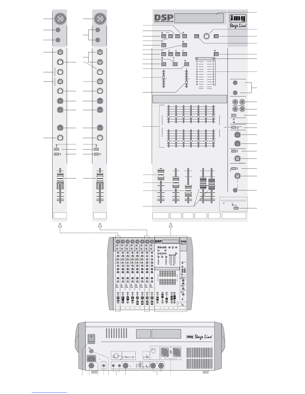
1 Übersicht der Bedienelemente und
Anschlüsse
1.1 Eingangskanäle (Abb. 1 und 2)
Die Mono-Eingangskanäle 1– 6 sind identisch.
Außerdem sind die beiden Stereo-Eingangskanäle
M1und M2 identisch.
1 XLR-Buchse MIC (sym.) für den Anschluss eines
Mikrofons
Hinweis: An die Mono-Kanäle entweder ein
Mikrofon an die XLR-Buchse anschließen oder
ein Gerät mit Line-Pegel-Ausgang an die Klinkenbuchse LINE (3).
Die aktivierte Phantomspeisung kann intern für
einzelne Mono-Kanäle durch Entfernen von
Drahtbrücken abgeschaltet werden – siehe Kapitel 4.1.
2 XLR-Buchse MIC (sym.) für den Anschluss eines
Mikrofons (für phantomgespeiste Mikrofone
nach Kapitel 4.2 die Brücke LK4 einlöten)
3 6,3-mm-Klinkenbuchse LINE (sym.) für den
Anschluss eines Mono-Gerätes mit Line-PegelAusgang (bei Anschluss eines Stereo-Gerätes
einen entsprechenden Adapter verwenden)
4 6,3-mm-Klinkenbuchsen LINE (sym.) für den An-
schluss eines Stereo-Gerätes mit Line-PegelAusgang
Hinweis: Bei Mono-Geräten nur die Buchse
LEFT/MONO anschließen. Das Signal wird dann
intern auf den rechten und linken Kanal geschaltet.
5 Buchse INSERT zum Einschleifen eines Effekt-
gerätes nach den Klangreglern (8, 9, 12)
Vorsicht!
Keine asymmetrischen Mikrofone anschließen,
wenn die Mikrofon-Phantomspeisung eingeschaltet ist: Es leuchtet die rote LED PHANTOM POWER +48 V über dem Schalter (50).
Diese Mikrofone können beschädigt werden.
Bitte klappen Sie die Seite 3 heraus. Sie sehen
dann immer die beschriebenen Bedienelemente
und Anschlüsse.
Inhalt
1 Operating Elements and Connec-
tions
1.1 Input channels (figs. 1 and 2)
The mono input channels 1– 6 are identical. The two
stereo input channels M1 and M2 are also identical.
1 XLR jack MIC (bal.) for connecting a microphone
Note: At the mono channels, either connect a
microphone to the XLR jack or a unit with line
level output to the 6.3 mm jack LINE (3).
The activated phantom power can be internally
switched off for individual mono channels by
removing solder wires – see chapter 4.1.
2 XLR jack MIC (bal.) for connecting a microphone
(for phantom-powered microphones, solder in
the solder wire LK4 according to chapter 4.2)
3 6.3 mm jack LINE (bal.) for connecting a mono
unit with line level output (when connecting a
stereo unit, use a corresponding adapter)
4 6.3 mm jack LINE (bal.) for connecting a stereo
unit with line level output
Note: For mono units, only connect the jack
LEFT/MONO. The signal will then be switched
internally to the right and left channels.
5 Jack INSERT for inserting an effect unit after the
equalizer controls (8, 9, 12) – see chapter 5.3;
Plug configuration:
tip = Send (output)
ring = Return (input)
sleeve = ground
6 Control GAIN for adjusting the input amplification
of the mono channel
Caution!
Never connect any unbalanced microphones
with the microphone phantom power switched
on: The red LED PHANTOM POWER +48 V
above the switch (50) will light up. These microphones may be damaged.

– siehe Kapitel 5.3;
Steckeranschlüsse:
Spitze = Send (Ausgang)
Ring = Return (Eingang)
Schaft = Masse
6 Regler GAIN zum Einstellen der Eingangsver-
stärkung des Mono-Kanals
7 Regler GAIN MIC zum Einstellen der Eingangs-
verstärkung für das Signal der Buchse MIC (2) und
Regler GAIN LINE zum Einstellen der Eingangsverstärkung für die Signale der Buchsen LINE (4)
Hinweis: Bei Anschluss eines Mikrofons und
eines Gerätes mit Line-Pegel-Ausgang lässt sich
das Mischverhältnis der beiden Signale mit diesen Reglern einstellen.
8 Klangregler HI (High) für die Höhen:
±15 dB/12kHz
9 Klangregler MID für die Mitten des Mono-Kanals:
±15 dB/350Hz –6 kHz
10 Regler zum Einstellen der Filterfrequenz für
die Klangregelung im Mittenbereich des MonoKanals: 350Hz – 6kHz
11 Klangregler MID für die Mitten des Stereo-
Kanals: ±15dB/2,5kHz
12 Klangregler LO (Low) für die Bässe:
in den Mono-Kanälen ±15dB/60 Hz
in den Stereo-Kanälen ±15dB/45 Hz
13 Effekt-Send-Regler EFF zum Einstellen des
Pegels, mit dem das Kanalsignal auf den internen Effektprozessor gemischt wird
Hinweis: Das Signal wird nach dem Fader ausgekoppelt (post-fader). Zusammen mit dem
AUX-Ausspielweg [Regler AUX (14)] kann es jedoch durch Ändern von Drahtbrücken für jeden
Kanal getrennt auch pre-fader abgenommen
werden – siehe dazu Kapitel 4.3
14 Regler AUX zum Mischen des Kanalsignals auf
den AUX-Ausspielweg [Buchse AUX (61)]
Hinweis: Das Signal wird nach dem Fader ausgekoppelt (post-fader). Zusammen mit dem
internen Effektweg [Regler EFF (13)] kann es
jedoch durch Ändern von Drahtbrücken für jeden
Kanal getrennt auch pre-fader abgenommen
werden – siehe dazu Kapitel 4.3
15 Monitor-Send-Regler FB (Foldback) zum Ein-
stellen des Pegels, mit dem das Kanalsignal auf
den Monitorkanal gemischt wird
Hinweis: Das Signal wird vor dem Kanalfader
(pre-fader) ausgekoppelt, kann jedoch durch Ändern von Drahtbrücken für jeden Kanal getrennt
auch post-fader abgenommen werden – siehe
dazu Kapitel 4.3.
16 Panoramaregler PAN zum Platzieren des Mono-
Kanalsignals in der Stereo-Basis
17 Balanceregler BAL; ist nur die Buchse LEFT/
MONO (4) angeschlossen oder nur die Buchse
MIC (2), arbeitet er als Panoramaregler
18 Anzeige PEAK
a Ist die Vorhörfunktion für den Kanal nicht akti-
viert [T aste PFL(19) nicht gedrückt], zeigt kurzes Aufleuchten der LED an, dass das Kanalsignal seinen Maximalpegel erreicht hat, bei
dem der Kanal gerade noch nicht übersteuert
wird.
b Ist die Vorhörfunktion für den Kanal aktiviert
[Taste PFL (19) gedrückt], leuchtet die LED
permanent.
19 PFL-Taste zum Vorhören des Kanals (Pre Fader
Listening) über einen an der Buchse PHONES
(58) angeschlossenen Kopfhörer
Bei gedrückter T aste ist gleichzeitig die Aussteuerungsanzeige (45) auf diesen Kanal geschaltet.
20 Routingtaste L-R/GROUP
Taste gedrückt: Der Kanal wird auf die Subgrup-
pe geschaltet.
nicht gedrückt: Der Kanal wird auf die Aus-
gangssumme LEFT/RIGHT geschaltet.
21 Pegelregler (Fader) des Kanals
1.2 Effekt- und Summensektion (Abb. 3)
22 Taste F/S (footswitch) zum Ein-/Ausschalten des
Einstellmodus für den Typ und die gewünschte
Funktion eines an der Buchse FOOTSWITCH
(66) angeschlossenen Fußschalters
– siehe Kap. 6.5.2
23 Taste RECALL zum Zurückstellen auf die Werks-
einstellung – siehe Kap. 6.5.3
Zum Zurückstellen beim Einschalten mit dem
Netzschalter POWER (60) die Tasten RECALL,
PGM (24) und EDIT (25) gedrückt halten.
24 Taste PGM zum Ein-/Ausschalten eines der 16
Effektprogramme
Ein Effektprogramm lässt sich nach dem Drücken der Taste PGM mit dem Drehschalter
EFFECT TYPE (40) auswählen.
25 Taste EDIT zum Aktivieren des Editiermodus für
ein angewähltes Effektprogramm
Bei aktiviertem Editiermodus blinkt die LED über
der Taste PGM (24).
26 Taste AUX MUTE, schaltet den Ausspielweg AUX
stumm [z. B. um ein an der Buchse AUX (61)
angeschlossenes Effektgerät stummzuschalten]
27 Taste DELAYzum Einschalten des Delay-Effekts
Bei eingeschaltetem Effekt lässt sich die Verzögerungszeit mit dem Regler EFFECT TYPE (40)
einstellen und bei gedrückter Taste REGEN (31)
mit dem Regler REGEN (33) die Ausklingzeit
(Anzahl der Echos).
28 Tasten USER PRESETS 1 bis 4 zum Speichern
und Aufrufen von vier verschiedenen Effekt-Voreinstellungen – siehe Kapitel 6.5.1
Die Tasten dienen auch zur Auswahl der Sprache im Display (39), indem beim Einschalten mit
dem Schalter POWER (60) die entsprechende
Taste USER PRESETS gedrückt gehalten wird:
Taste 1 für Englisch
Taste 2 für Französisch
Taste 3 für Deutsch
Taste 4 für Spanisch
7 Control GAIN MIC for adjusting the input amplifi-
cation for the signal of the jack MIC (2) and control GAIN LINE for adjusting the input amplification for the signals of the jacks LINE (4)
Note: When connecting a microphone and a unit
with line level output, use these controls to adjust
the mixing ratio of the two signals.
8 Equalizer controls HI (High) for the high frequen-
cies:
±15 dB/12kHz
9 Equalizer control MID for the midrange frequen-
cies of the mono channel:
±15 dB/350Hz –6 kHz
10 Control for adjusting the filter frequency for the
equalizer in the midrange of the mono channel:
350Hz –6kHz
11 Equalizer control MID for the midrange frequen-
cies of the stereo channel: ±15dB/2.5kHz
12 Equalizer controls LO (Low) for the bass fre-
quencies:
in the mono channels: ±15dB/60 Hz
in the stereo channels: ±15dB/45 Hz
13 Effect send controls EFF for adjusting the level at
which the channel signal is mixed to the internal
effect processor
Note: The signal is taken after the fader (postfader). However, together with the AUX send
way [control AUX (14)], it can also be taken
ahead of the fader (pre-fader) separately for
each channel by modifying solder wires – for this
purpose see chapter 4.3.
14 Controls AUX for mixing the channel signal to the
AUX send way [jack AUX (61)]
Note: The signal is taken after the fader (postfader). However, together with the internal effect
way [control EFF (13)] it can also be taken ahead
of the fader (pre-fader) separately for each channel by modifying solder wires – for this purpose
see chapter 4.3.
15 Monitor Send controls FB (Foldback) for adjust-
ing the level at which the channel signal is mixed
to the monitor channel
Note: The signal is taken ahead of the channel
fader (pre-fader), however, it can also be taken
post-fader separately for each channel by
modifying solder wires – for this purpose see
chapter 4.3.
16 Panorama control PAN for placing the mono
channel signal on the stereo base
17 Balance control BAL; if only the jack LEFT/
MONO (4) or only the jack MIC (2) is connected,
it operates as a panorama control
18 LEDs PEAK
a If the pre-fader listening function for the chan-
nel has not been activated [button PFL (19)
not pressed], the LED will light up shortly to
indicate that the channel signal has reached
its maximum level at which the channel is
close to overload.
b If the pre-fader listening function for the
channel has been activated [button PFL (19)
pressed], the LED will light permanently.
19 PFL button for pre-fader listening to the channel
(Pre Fader Listening) via headphones connected to the jack PHONES (58)
With the button pressed, the LED level indication
(45) is simultaneously switched to this channel.
20 Routing button L-R/GROUP
button pressed: The channel is switched to
the subgroup.
button not pressed: The channel is switched to
the master output LEFT/
RIGHT.
21 Level controls (fader) of the channel
1.2 Effect and master section (fig. 3)
22 Button F/S (footswitch) for switching on or off the
adjusting mode for the type and the desired function of a footswitch connected to the jack
FOOTSWITCH (66) – see chapter 6.5.2
23 Button RECALL for reset to the factory-set
values – see chapter 6.5.3
For reset, keep the buttons RECALL, PGM (24),
and EDIT (25) pressed when switching on the
unit with the mains switch POWER (60).
24 Button PGM for switching on or off one of 16
effect programmes
An effect programme can be selected with the
rotary switch EFFECT TYPE (40) after pressing
the button PGM.
25 Button EDIT for activating the edit mode for a
selected effect programme
With the effect mode activated, the LED above
the button PGM (24) will flash.
26 Button AUX MUTE, for muting the AUX send way
[e. g. for muting an effect unit connected to the
jack AUX (61)]
27 Button DELAYfor switching on the delay effect
With the effect activated, the delay time can be
adjusted with the control EFFECT TYPE (40),
and with the button REGEN (31) pressed, the
regeneration time (number of echoes) can be
adjusted with the control REGEN (33).
28 Buttons USER PRESETS 1 to 4 for memorizing
and recalling four different effect presettings
– see chapter 6.5.1
The buttons also serve for selecting the language
on display (39) by keeping the corresponding
button USER PRESETS pressed while the unit is
switched on with the switch POWER (60):
button 1 for English
button 2 for French
button 3 for German
button 4 for Spanish
29 Button EFFECT EQ, offering four sound adjust-
ments for the effect signal:
1. warm (LED “WARM” will light up)
2. bright (LED “BRIGHT” will light up)
3. warm + bright (LEDs “WARM” and “BRIGHT”
will light up)
4. no effect on sound (LEDs off)
5
GB
D
A
CH

29 Taste EFFECT EQ schaltet zwischen vier Klang-
einstellungen für das Effektsignal um:
1. warm (LED „WARM“ leuchtet)
2. hell (LED „BRIGHT“ leuchtet)
3. warm + hell (LEDs „WARM“ und „BRIGHT“
leuchten
4. keine Klangbeeinflussung (LEDs aus)
30 Taste EFFECT zum Einschalten des Effekt-Pro-
zessors
Bei eingeschaltetem Effekt leuchtet die darüber
liegende LED „ON“.
Bei Übersteuerung leuchtet die darüber liegende
LED „PEAK“ auf. Dann die entsprechenden Regler EFF (13) zurückdrehen.
31 Taste REGEN zum Aktivieren des Schiebereg-
lers REGEN (33), mit dem die Delay-Ausklingzeit (Anzahl der Echos) einstellbar ist
Die T aste REGEN lässt sich nur aktivieren, wenn
zuvor mit der Taste DELAY(27) der Delay-Effekt
eingeschaltet wurde.
32 Schieberegler EFFECT TO FB, mischt das in-
terne Effektsignal auf den Monitorkanal FB
33 Schieberegler REGEN zum Einstellen der
Delay-Ausklingzeit (Anzahl der Echos)
Der Regler ist nur aktiviert, wenn die Tasten
DELAY(27) und REGEN (31) eingeschaltet sind.
34 Equalizer zur Klangeinstellung der Ausgangs-
summe [Taste AMP (51) nicht gedrückt] oder zur
Klangeinstellung der Subgruppe GROUP [Taste
AMP gedrückt]
35 Summenregler für die Stereo-Subgruppe
Das Subgruppensignal wird auf die Ausgangssumme LEFT/RIGHT gemischt.
36 Summenregler für den Monitorkanal FB
37 Schieberegler EFFECT zum Mischen des über
den internen Effektprozessor erzeugten Effektsignals auf die Ausgangssumme LEFT/RIGHT
38 Pegelregler für die Ausgangssumme LEFT/
RIGHT
39 Display zur Anzeige von Effekteinstellungen,
Bedienungshinweisen, Fehler- und Warnmel-
dungen; zur Auswahl der angezeigten Sprache
siehe Punkt 28, Tasten USER PRESETS
40 Endlosdrehschalter EFFECT TYPE:
je nach aktiviertem Modus zur Auswahl eines
Effekts, der Delay-Zeit, eines der 16 Effektprogramme oder der Fußschalter-Funktion
41 Taste HELP zur Anzeige von Bedienungshinwei-
sen im Display (39)
42 Taste PARAMETER/PGM CHECK:
1. Zur Anzeige des Effekts, wenn eines der 16
Effektprogramme eingeschaltet ist.
2. Bei gedrückter Taste lässt sich im Editiermodus für die Effektprogramme mit dem Drehschalter EFFECTTYPE (40) der Effekt ändern.
3. Bei gedrückter Taste lässt sich im Einstellmodus für den Fußschalter mit dem Drehschalter EFFECT TYPE der Fußschaltertyp
und die gewünschte Schaltfunktion einstellen.
43 Taste STANDBY, schaltet die Ausgangssumme
LEFT/RIGHT und den Monitorkanal FB stumm
(z.B. zum Stummschalten der Beschallung ohne
aktuelle Pegeleinstellungen zu verändern)
44 Übersteuerungsanzeige für die interne Endstufe
Beim Aufleuchten den Regler AMP LEVEL (55)
zurückdrehen [auch wenn die Aussteuerungsanzeige (45) noch keine Übersteuerung anzeigt].
45 Aussteuerungsanzeige
Ist keine der Tasten PFL (19), L-R /SPLIT (54)
und METER/ PHONES SELECT (56) gedrückt,
wird der Pegel des Summenkanals LEFT/RIGHT
angezeigt.
46 6,3-mm-Klinkenbuchsen (asym.) für den Zusatz-
eingang AUX INPUT
Hinweis: Bei Mono-Geräten nur die obere Buchse
L/MONO anschließen. Das Signal wird dann
intern auf den rechten und linken Kanal geschaltet.
47 Cinch-Buchsen TAPE REC, um die Ausgangs-
summe LEFT/RIGHT auf ein Aufnahmegerät zu
geben
Der Ausgangspegel ist von den Fadern LEFT/
RIGHT (38) abhängig.
48 Cinch-Buchsen TAPE PLAY für die Wiedergabe
eines Aufnahmegerätes
49 Taste TAPE PLA Y
Bei gedrückter T aste wird das Signal der darüber
liegenden Buchsen (48) auf die Ausgangssumme geschaltet (z. B. zur Wiedergabe einer
Tonaufnahme).
50 versenkter Schalter (mit roter Kontroll-LED) zum
zentralen Zuschalten der 48-V-Phantomspeisung für die XLR-Buchsen MIC (1) der MonoEingangskanäle; erforderlich beim Anschluss
von Kondensator- oder Elektretmikrofonen, die
mit 48-V-Phantomspeisung arbeiten
51 Zuordnungsschalter für den Equalizer (34)
Taste gedrückt: Der Klang der Subgruppe
GROUP ist einstellbar.
nicht gedrückt: Der Klang der Ausgangssumme
LEFT/RIGHT ist einstellbar.
Im Split-Modus [T aste L-R/SPLIT
(54) gedrückt] sind die oberen
Regler der Mono-Ausgangssumme zugeordnet und die unteren
Regler dem Monitorweg FB.
52 Regler AUX IN LEVELzum Mischen des Signals
der Buchsen AUX INPUT(46) auf die Ausgangssumme LEFT/RIGHT
53 Regler AUX IN TO FB zum Mischen des Signals
der Buchsen AUX INPUT (46) auf den Monitorkanal FB
Das Signal wird pre-fader abgenommen und
ist damit vom Regler AUX IN LEVEL (52) unabhängig.
Vorsicht! Bei anliegender Phantomspannung
dürfen an den Mikrofoneingängen der MonoKanalzüge keine asymmetrischen Mikrofone
angeschlossen sein, da diese zerstört werden
könnten. Zum Abschalten der Phantomspeisung einzelner Kanäle siehe Kapitel 4.1.
30 Button EFFECT for switching on the effect pro-
cessor
With the effect activated, the LED “ON” above
the button lights up.
In case of overload, the LED “PEAK” above the
button lights up. In this case, turn back the corresponding control EFF (13).
31 Button REGEN for activating the sliding control
REGEN (33) for adjusting the delay regeneration
time (number of echoes)
The button REGEN can only be activated after
the delay effect has been switched on with the
button DELAY(27).
32 Sliding control EFFECT TO FB, for mixing the
internal effect signal to the monitor channel FB
33 Sliding control REGEN for adjusting the delay
regeneration time (number of echoes)
The control is only activated if the buttons
DELAY(27) and REGEN (31) are switched on.
34 Equalizer for sound adjustment of the master
output [button AMP (51) not pressed] or for
sound adjustment of the subgroup GROUP [button AMP pressed]
35 Master control for the stereo subgroup
The subgroup signal is mixed to the master output LEFT/RIGHT.
36 Master control for the monitor channel FB
37 Sliding control EFFECT for mixing the effect sig-
nal created by the internal effect processor to the
master output LEFT/RIGHT
38 Level controls for the master output LEFT/RIGHT
39 Display for effect adjustments, operation hints,
error and warning messages; for selecting the
language on display see item 28, buttons USER
PRESETS
40 Continuous rotary switch EFFECT TYPE:
for selecting an effect, the delay time, one of
16 effect programmes, or the footswitch function
– depending on the mode activated
41 Button HELP for indicating operation hints on the
display (39)
42 Button PARAMETER/PGM CHECK:
1. For indicating the effect if one of the 16 effect
programmes has been switched on.
2. With the button pressed, in the edit mode
the effect can be modified for the effect programmes with the rotary switch EFFECT
TYPE (40).
3. With the button pressed in the adjusting mode,
the type of footswitch and the desired switching function can be adjusted for the footswitch
with the rotary switch EFFECT TYPE.
43 Button STANDBY, for muting the master output
LEFT/RIGHT and the monitor channel FB (e. g.
for muting the PA sound without modifying the
current level adjustments)
44 Overload indication for the internal power amplifier
If it lights up, turn back the control AMP LEVEL
(55) [even if the LED level indication (45) does
not signalize any overload yet].
45 LED level indication
If none of the buttons PFL (19), L-R/SPLIT (54),
and METER/ PHONES SELECT (56) has been
pressed, the level of the master channel LEFT/
RIGHT will be indicated.
46 6.3mm jacks (unbal.) for the additional input
AUX INPUT
Note: In case of mono units, only connect the
upper jack L /MONO: The signal will then be
switched internally to the right and left channels.
47 Phono jacks TAPE REC, for feeding the master
output LEFT/RIGHT to a recorder
The output level depends on the faders LEFT/
RIGHT (38).
48 Phono jacks TAPE PLAY for the reproduction of
a recorder
49 Button TAPE PLAY
With the button pressed, the signal of the jacks
(48) above the button is switched to the master
output (e.g. for reproducing an audio recording).
50 Recessed switch (with red indicating LED) for
central connection of the 48V phantom power for
the XLR jacks MIC (1) of the mono input channels; required for connecting capacitor or electret
microphones operating at a 48V phantom power
51 Assign switch for the equalizer (34)
button pressed: The sound of the subgroup
GROUP can be adjusted.
button not pressed: The sound of the master out-
put LEFT/RIGHT can be adjusted. In the split mode [button L-R/SPLIT (54) pressed],
the upper controls are assigned to the mono master
output and the lower controls
to the monitor way FB.
52 Control AUX IN LEVEL for mixing the signal of
the jacks AUX INPUT (46) to the master output
LEFT/RIGHT.
53 Control AUX IN TO FB for mixing the signal of the
jacks AUX INPUT(46) to the monitor channel FB
The signal is taken pre-fader and is thus independent of the control AUX IN LEVEL(52).
54 Switch L-R/SPLIT for splitting the stereo power
amplifier (split mode)
button pressed: The left channel reproduces
the master channel LEFT/
RIGHT in mono, the right
channel the monitor channel
FB.
button not pressed: The power amplifier repro-
duces the master channel in
stereo.
Note: The selection is simultaneously made for
the LED level indication (45), the headphone
jack PHONES (58), the jacks LINE OUT/SUB
OUT (65), and the equalizer (34)
Caution! With the phantom power applied,
never connect any unbalanced microphones to
the microphone inputs of the mono channels,
otherwise they may be damaged. To switch off
the phantom power of individual channels see
chapter 4.1.
6
GB
D
A
CH

54 Schalter L-R/ SPLIT zum Trennen der Stereo-
Endstufe (Split-Modus)
Taste gedrückt: Der linke Kanal gibt den Sum-
menkanal LEFT/RIGHT in Mono
wieder, der rechte Kanal den
Monitorkanal FB.
nicht gedrückt: Die Endstufe gibt den Summen-
kanal in Stereo wieder.
Hinweis: Die Umschaltung erfolgt gleichzeitig
auch für die Aussteuerungsanzeige (45), die
Kopfhörerbuchse PHONES (58), die Buchsen
LINE OUT/ SUB OUT(65) und den Equalizer (34)
55 Lautstärkeregler AMP LEVEL für die ange-
schlossenen Lautsprecherboxen
56 Auswahlschalter METER/PHONES SELECT für
die Kopfhörerbuchse (58) und die Aussteuerungsanzeige (45)
Taste gedrückt: Der Monitorkanal FB wird ange-
zeigt und lässt sich über einen
Kopfhörer abhören.
nicht gedrückt: Die Ausgangssumme LEFT/
RIGHT wird angezeigt und lässt
sich abhören.
Hinweis: Ist eine der PFL-Tasten (19) gedrückt,
wird immer der dazugehörige Kanal angezeigt
und kann über einen Kopfhörer abgehört werden.
57 Lautstärkeregler für einen an der Buchse
PHONES (58) angeschlossenen Kopfhörer
58 6,3-mm-Klinkenbuchse PHONES zum Anschluss
eines Stereo-Kopfhörers (Impedanz ≥ 32Ω)
Das Ausgangssignal wird von der Aussteuerungsanzeige (45) angezeigt und ist von den
Tasten PFL (19), L-R/SPLIT (54) sowie METER/
PHONES SELECT (56) abhängig.
59 Taste zum Einschalten der 150-Hz-Aktivfrequenz-
weiche, um Mittel-/Hochtonlautsprecherboxen
über die integrierte Endstufe zu betreiben und
Subwooferboxen über einen zusätzlichen Verstärker, der an die Buchsen LINE OUT/SUB
OUT (65) angeschlossen wird – siehe auch
Kapitel 5.9.3
1.3 Rückseite
60 Netzschalter POWER
61 6,3-mm-Klinkenbuchse (asym.) für den Ausspiel-
weg AUX
Hinweis: Bei gedrückter Taste AUX MUTE (26)
ist dieser Ausgang stummgeschaltet.
62 Netzbuchse zum Anschluss an eine Steckdose
(230V~/50Hz) über das beiliegende Netzanschlusskabel
63 6,3-mm-Klinkenbuchse (asym.) für den Ausgang
des Monitorkanals FB
64 Sicherungshalter; eine durchgebrannte Siche-
rung nur durch eine gleichen Typs ersetzen
65 6,3-mm-Klinkenbuchsen (asym.) für die Aus-
gangssumme LEFT/RIGHT (Line-Pegel)
Ist die Taste (59) für das 150-Hz-Aktivfilter ge-
drückt, liegen hier die Bass-Signale zur Weiterleitung an einen Subwoofer-Verstärker an.
Ist die Taste L-R /SPLIT (54) gedrückt, liegt an
der Buchse LEFT das Mono-Signal der Ausgangssumme LEFT/RIGHT an und an der
Buchse RIGHTdas Signal des Monitorkanals FB.
66 6,3-mm-Klinkenbuchse (2-polig) für einen Fuß-
schalter zum Ein-/Aus- oder Umschalten von
Effekten
Die Art des Fußschalters (Ein-/Ausschalter oder
Taster) und die zu schaltende Funktion lässt sich
auswählen – siehe Kapitel 6.5.2
67 6,3-mm-Klinkenbuchsen (asym.) zum Einschlei-
fen eines zusätzlichen Gerätes zur Klangbearbeitung (z. B. Equalizer) in die Endstufe nach
dem Lautstärkeregler AMP(55) – siehe Kap. 5.5;
Steckeranschlüsse:
Spitze = Send (Signalausgang)
Ring = Return (Signaleingang)
Schaft = Masse
68 Speakon
®
-Buchsen zum Anschluss der Laut-
sprecher (Impedanz min. 4Ω);
Buchsenbelegung siehe Kap. 5.9
2 Hinweise für den sicheren Gebrauch
Dieses Gerät entspricht der Richtlinie für elektromagnetische Verträglichkeit 89/336/EWG und der Niederspannungsrichtlinie 73/23/EWG.
Beachten Sie unbedingt die folgenden Punkte:
●
Das Gerät ist nur zur Verwendung in Innenräumen
geeignet. Schützen Sie es vor Tropf- und Spritzwasser, hoher Luftfeuchtigkeit und Hitze (zulässiger Einsatztemperaturbereich 0– 40°C).
●
Stellen Sie keine mit Flüssigkeit gefüllten Gefäße,
z.B. Trinkgläser, auf das Gerät.
●
Die im Gerät entstehende Wärme muss durch
Luftzirkulation abgegeben werden. Decken Sie
die Lüftungsöffnungen nicht ab.
●
Stecken Sie nichts durch die Lüftungsöffnungen.
Dies kann zu einem elektrischen Schlag führen!
●
Nehmen Sie das Gerät nicht in Betrieb bzw. ziehen
Sie sofort den Netzstecker aus der Steckdose:
1. wenn sichtbare Schäden am Gerät oder an der
Netzanschlussleitung vorhanden sind,
2. wenn nach einem Sturz oder Ähnlichem der
Verdacht auf einen Defekt besteht,
3. wenn Funktionsstörungen auftreten.
Lassen Sie das Gerät in jedem Fall in einer Fachwerkstatt reparieren.
●
Ziehen Sie den Netzstecker nie an der Zuleitung
aus der Steckdose, fassen Sie immer am Stecker
an.
●
Verwenden Sie zum Reinigen nur ein trockenes,
weiches Tuch, niemals Wasser oder Chemikalien.
●
Wird das Gerät zweckentfremdet, falsch angeschlossen bzw. bedient oder nicht fachgerecht repariert, kann keine Haftung für daraus resultierende Sach- oder Personenschäden und keine
Garantie für das Gerät übernommen werden.
Achtung!
Das Gerät wird mit lebensgefährlicher Netzspannung (230V~) versorgt. Nehmen Sie nie selbst Eingriffe im Gerät vor. Durch unsachgemäßes Vorgehen besteht die Gefahr eines elektrischen Schlages.
55 Volume control AMP LEVEL for the speaker sys-
tems connected
56 Selector switch METER/ PHONES SELECT for
the headphone jack (58) and the LED level indication (45)
button pressed: The monitor channel FB is
indicated and can be monitored via headphones.
button not pressed: The master output LEFT/
RIGHT is indicated and can
be monitored.
Note: With one of the PFL buttons (19) pressed,
the corresponding channel is always indicated
and can be monitored via headphones.
57 Volume control for headphones connected to the
jack PHONES (58)
58 6.3mm jack PHONES for connecting stereo
headphones (impedance ≥ 32Ω)
The output signal is indicated by the LED level
indication (45) and depends on the buttons PFL
(19), L-R/SPLIT (54), and METER/PHONES
SELECT (56).
59 Button to switch on the 150Hz active crossover
network to operate midrange/treble speaker
systems via the integrated power amplifier and
subwoofer systems via an additional amplifier
connected to the jacks LINE OUT/SUB OUT (65)
– also see chapter 5.9.3.
1.3 Rear Panel
60 POWER switch
61 6.3mm jack (unbal.) for the AUX send way
Note: With the button AUX MUTE (26) pressed,
this output is mute.
62 Mains jack for connecting a mains socket
(230 V~ / 50 Hz) via the supplied mains connection cable
63 6.3mm jack (unbal.) for the output of the monitor
channel FB
64 Fuse holder; always replace a burnt-out fuse by
one of the same type only
65 6.3mm jacks (unbal.) for the master output
LEFT/RIGHT (line level)
If the button (59) for the 150 Hz active filter is
pressed, the bass signals for passing on to a
subwoofer amplifier are applied here.
If the button L-R/SPLIT (54) is pressed, the
mono signal of the master output LEFT/RIGHT is
applied to the jack LEFT, and the signal of the
monitor channel FB to the jack RIGHT.
66 6.3mm jack (2-pole) for a footswitch for switch-
ing on or off or selecting effects
The type of footswitch (on-off switch or momentary switch) and the function to be switched can
be selected – see chapter 6.5.2
67 6.3mm jacks (unbal.) for inserting an additional
unit for sound processing (e. g. equalizer) into
the power amplifier after the volume control AMP
(55) – see chapter 5.5;
plug configuration:
tip = Send (signal output)
ring = Return (signal input)
sleeve = ground
68 Speakon
®
jacks for connecting the speakers
(minimum impedance 4Ω);
configuration see chapter 5.9
2 Safety Notes
This unit corresponds to the directive for electromagnetic compatibility 89/ 336 /EEC and to the low
voltage directive 73/23/EEC.
Please observe the following items in any case:
●
The unit is suitable for indoor use only. Protect it
against dripping water and splash water, high air
humidity, and heat (admissible ambient temperature range 0– 40°C).
●
Do not place any vessel filled with liquid on the
unit, e.g. a drinking glass.
●
The heat generated within the unit must be carried
off by air circulation. Never cover the air vents of
the housing.
●
Do not insert anything into the air vents. This may
result in an electric shock!
●
Do not operate the unit or immediately disconnect
the plug from the mains socket
1. if there is visible damage to the unit or to the
mains cable,
2. if a defect might have occurred after the unit
was dropped or suffered a similar accident,
3. if malfunctions occur.
In any case the unit must be repaired by skilled
personnel.
●
Never pull the mains cable for disconnecting the
mains plug from the socket, always seize the plug.
●
For cleaning only use a dry, soft cloth, by no
means chemicals or water.
●
No guarantee claims for the unit or liability for any
resulting personal damage or material damage
will be accepted if the unit is used for other purposes than originally intended, if it is not correctly
connected, operated or not repaired in an expert
way.
●
If the unit is to be put out of operation definitively,
take it to a local recycling plant for a disposal
which is not harmful to the environment.
●
Important for U.K. Customers!
The wires in this mains lead are coloured in accordance with the following code:
green/yellow = earth
blue = neutral
brown = live
As the colours of the wires in the mains lead of this
appliance may not correspond with the coloured
markings identifying the terminals in your plug,
proceed as follows:
1. The wire which is coloured green and yellow
must be connected to the terminal in the plug
which is marked with the letter E or by the earth
Attention!
The unit is supplied with hazardous mains voltage
(230V~). Leave servicing to skilled personnel only.
Inexpert handling may cause an electric shock
hazard.
7
GB
D
A
CH

●
Soll das Gerät endgültig aus dem Betrieb genommen werden, übergeben Sie es zur umweltgerechten Entsorgung einem örtlichen Recyclingbetrieb.
3 Einsatzmöglichkeiten
Der Power Mixer PMX-700DSP ist eine Kombination aus einem 8-Kanal-Mischpult, einem Effektprozessor (DSP = Digital Signal Processor) und einer
Stereo-Endstufe mit 2 x 300W
RMS. Er ist speziell für
Musiker und den Einsatz auf der Bühne ausgelegt.
6 Mono- und 2 Stereo-Eingangskanäle für Mikrofone oder Geräte mit Line-Pegel-Ausgang lassen
sich auf die Ausgangssumme mischen. Jeder Eingangskanal befindet sich auf einer separaten Leiterplatte und ist mit diversen Einstellmöglichkeiten ausgestattet, z.B.:
– Gain-Regler (bei den Stereo-Kanälen getrennt
für Mic und Line)
– Insert-Buchse in den Mono-Kanälen
– für die Mikrofoneingänge zuschaltbare Phantom-
speisung (für die Stereo-Kanäle durch Lötbrücken)
– 3fach-Klangregelung (bei den Mono-Kanälen ist
zusätzlich die Mittenfrequenz einstellbar)
– 3 Auskoppelregler (durch Lötbrücken wählbar
pre-EQ, pre-fader oder post-fader)
– Panorama- bzw. Balanceregler
– Routingtaste, um das Kanalsignal auf die Stereo-
Subgruppe zu mischen
– LED für Peak- und PFL-Anzeige
Alle Eingangskanäle, die Ausgangssumme und der
Monitorkanal lassen sich über einen Kopfhörer abhören.
Im Split-Modus kann der linke Kanal der Endstufe den Summenkanal in Mono zur Saalbeschallung verstärken und der rechte Kanal den Monitorkanal zur Bühnenbeschallung. Durch Aktivierung
der integrierten 150-Hz-Frequenzweiche lässt sich
mit einem zusätzlichen PA-Verstärker ein aktives
2-Wege-Lautsprechersystem mit Subwoofer-Boxen
realisieren, um damit einen höheren Schallpegel zu
erhalten.
4 Modifikationen der Eingangskanäle
Bei Bedarf vor dem Anschluss des PMX-700DSP
die folgenden Modifikationen der Eingangskanäle
durchführen.
1) Das Mischpult ausschalten und den Stecker aus
der Steckdose ziehen.
2) Die folgenden 10 Kreuzschlitzschrauben herausschrauben:
auf der Rückseite die oberen 3 Schrauben,
unterhalb der vorderen Kante die 3 Schrauben,
an der linken und rechten Kante der Frontplatte
jeweils die 2 Schrauben.
3) Das Geräteoberteil mit den Bedienelementen
vorsichtig nach oben abnehmen, sodass keine
Verbindungsleitungen abreißen.
4) Die Modifikationen nach den entsprechenden
Kapiteln 4.1– 4.3 durchführen.
5) Das Gerät wieder zusammenschrauben.
4.1 Phantomspeisung für einzelne Mono-
Kanäle abschalten
Die 48-V-Phantomspeisung für die Mono-Kanäle ist
zentral zuschaltbar. Sie kann jedoch für jeden dieser
Kanäle einzeln abgeschaltet werden, wenn sowohl
asymmetrische als auch phantomgespeiste Mikrofone angeschlossen werden sollen. Dazu auf der
Platine des betreffenden Kanals die Drahtbrücke
LK6 durchtrennen. Die Drahtbrücke befindet sich
auf Höhe der XLR-Buchse und ist seitlich mit
„FIT LK6 FOR +48V“ beschriftet.
4.2 Phantomspeisung für einzelne Stereo-
Kanäle dazuschalten
Wird in einem oder in beiden Stereo-Kanälen die
Mikrofon-Phantomspeisung benötigt, die Brücke
LK4 auf der entsprechenden Leiterplatte einlöten.
Die Position für die Drahtbrücke befindet sich auf
Höhe der XLR-Buchse und ist mit „FIT LK4 FOR
+48V“ gekennzeichnet. Die Phantomspeisung lässt
sich danach zusammen mit der Phantomspeisung
für die Mono-Kanäle durch die Taste PHANTOM
POWER +48V (50) zuschalten.
4.3 Ausspielwege modifizieren
Die folgenden Modifikationen sind aufwändig und
können nur in einer Fachwerkstatt ausgeführt werden, weil die Leiterplatten der entsprechenden Eingangskanäle ausgebaut werden müssen. Die Drahtbrücken, die dazu jeweils entfernt und eingelötet
werden müssen, sind auch aus dem Blockschaltbild
auf der Seite 53 ersichtlich.
1. Das Signal für den internen Effektprozessor und
für den Ausspielweg AUX wird jeweils nach dem
Kanalfader ausgekoppelt (post-fader). Gemeinsam für die beiden Wege kann das Signal für
jeden Eingangskanal separat auch pre-fader abgenommen werden. In den betreffenden Kanälen
die Drahtbrücke LK1 entfernen und eine Brücke
in Position LK2 einlöten.
2. Das Signal für den Monitorkanal FB wird vor dem
Kanalfader ausgekoppelt (pre-fader), kann aber
auch post-fader abgenommen werden, wenn
anstelle des Monitorkanals ein zweiter Effektweg
benötigt wird.
In den entsprechenden Mono-Kanälen LK8 entfernen und LK7 einlöten.
In den entsprechenden Stereo-Kanälen LK6 entfernen und LK5 einlöten.
3. Das Pre-Fader-Signal wird jeweils nach der Klangeinstellung abgenommen (post-EQ), kann jedoch auch vor dieser ausgekoppelt werden.
In den entsprechenden Mono-Kanälen LK9 entfernen und LK10 einlöten.
In den entsprechenden Stereo-Kanälen LK7 entfernen und LK8 einlöten.
Vorsicht!
Für diese Änderungen muss das Gerät geöffnet
werden. Darum dürfen sie nur von einer qualifizierten Fachkraft durchgeführt werden.
symbol , or coloured green or green and
yellow.
2. The wire which is coloured blue must be connected to the terminal which is marked with the
letter N or coloured black.
3. The wire which is coloured brown must be connected to the terminal which is marked with the
letter L or coloured red.
Warning – This appliance must be earthed.
3 Applications
The power mixer PMX-700DSP combines an
8-channel mixer, an effect processor (DSP = digital
signal processor), and a stereo power amplifier of
2 x 300 W
RMS. It has specially been designed for
musicians and applications on stage.
6 mono input channels and 2 stereo input channels for microphones or units with line level output
can be mixed to the master output. Each input channel is situated on a separate PCB and is equipped
with various adjusting facilities, e.g.:
– gain control (for stereo channels separated for
Mic and Line)
– insert jack in the mono channels
– phantom power to be connected for the micro-
phone inputs (for the stereo channels by means
of solder wires)
– 3-way equalizer (for mono channels, the
midrange frequency is adjustable in addition)
– 3 send controls (pre-EQ, pre-fader, or post-fader
to be selected by solder wires)
– panorama or balance control
– routing button for mixing the channel signal to the
stereo subgroup
– LED for indicating peak and PFL
All input channels, the master output, and the moni-
tor channel can be monitored via headphones.
In the split mode, the left channel of the power
amplifier is able to amplify the master channel in
mono for PAapplication in halls; and the right chan-
nel the monitor channel for PAapplication on stage.
By activating the integrated 150 Hz crossover network, together with an additional PA amplifier an
active 2-way speaker system with subwoofer cabinets can be realized in order to obtain a higher
sound level.
4 Modifications of the Input Channels
If required, make the following modifications of the
input channels prior to connecting the PMX-700DSP.
1) Switch off the mixer and disconnect the mains
plug from the socket.
2) Unscrew the following 10 recessed head screws:
the upper 3 screws on the rear side,
the 3 screws below the front edge,
the 2 screws each at the left and right edges of
the front panel.
3) Carefully remove the upper part of the unit with
the operating elements in an upward movement
without tearing off any connections.
4) Make the modifications according to the corresponding chapters 4.1– 4.3.
5) Reassemble the unit.
4.1 Disconnecting the phantom power for
individual mono channels
The 48V phantom power for the mono channels can
be centrally connected. However, it can be switched
off individually for each of these channels for connecting both unbalanced microphones and phantom-powered microphones. For this purpose, separate the solder wire LK6 on the PCB of the corresponding channel. The solder wire is situated at the
level of the XLR jack and bears the mark “FIT LK6
FOR +48V” on its side.
4.2 Connecting the phantom power for individual stereo channels
If the microphone phantom power is required in one
or both stereo channels, solder in the solder wire
LK4 on the corresponding PCB.
The position for the solder wire is at the level of the
XLR jack and bears the mark “FIT LK4 FOR +48V”.
The phantom power can then be connected via the
button PHANTOM POWER +48V (50) together with
the phantom power for the mono channels.
4.3 Modifying the send ways
The following modifications require a lot of effort and
can only be made by skilled personnel as the PCBs
of the corresponding input channels have to be removed. The solder wires which have to be removed
and soldered in respectively for this purpose can
also be found in the block diagram on page 53.
1. The signal for the internal effect processor and
for the AUX send way is taken after the channel
fader (post-fader) respectively. For both ways
together, the signal can also be taken pre-fader
separately for each input channel. Remove the
solder wire LK1 in the corresponding channels
and solder in a solder wire at position LK2.
2. The signal for the monitor channel FB is taken
ahead of the channel fader (pre-fader), but is can
also be taken post-fader if a second effect way is
required instead of the monitor channel.
In the corresponding mono channels, remove
LK8 and solder in LK7.
In the corresponding stereo channels, remove
LK6 and solder in LK5.
3. The pre-fader signal is respectively taken after
the sound adjustment (post-EQ), but it can also
be taken ahead of it.
In the corresponding mono channels, remove
LK9 and solder in LK10.
In the corresponding stereo channels, remove
LK7 and solder in LK8.
Caution!
For these modifications the unit must be opened.
Therefore, they must be performed by qualified
skilled personnel only.
8
GB
D
A
CH

5 Geräte anschließen
Vor dem Anschließen von Geräten bzw. Ändern bestehender Anschlüsse das Mischpult ausschalten.
5.1 Mikrofone
1) Benötigen die verwendeten Mikrofone keine Phantomspeisung, den versenken Schalter PHANTOM
POWER +48 V (50) nicht drücken. Die darüber
liegende rote LED darf nach dem Einschalten des
Mischpults nicht leuchten. In diesem Fall können
sowohl symmetrisch als auch asymmetrisch beschaltete Mikrofone angeschlossen werden.
2) Für den Betrieb von phantomgespeisten Mikrofonen den Schalter PHANTOM POWER +48V mit
einem dünnen Gegenstand (z.B. Kugelschreiber)
hineindrücken. Nach dem Einschalten des Mischpults leuchtet die darüber liegende rote LED. An
allen XLR-Buchsen MIC (1) der Mono-Eingangskanäle liegt die 48-V-Phantomspeisung an.
Intern ist die Phantomspeisung in den MonoKanälen einzeln abschaltbar (Kap. 4.1) und in den
Stereo-Kanälen einzeln dazuschaltbar (Kap. 4.2).
3) Die Mikrofone an die XLR-Buchsen MIC (1 und
2) anschließen.
Hinweis: Es kann nicht zwischen den XLR-Buchsen
MIC und den Klinkenbuchsen LINE umgeschaltet
werden. Darum in den Mono-Kanälen entweder die
Buchse MIC (1) oder die Buchse LINE (3) anschließen. Wird an einem Stereo-Kanal ein Mikrofon
an die Buchse MIC (2) und ein Gerät mit Line-PegelAusgang an die Buchsen LINE (4) angeschlossen,
lässt sich das Mischverhältnis der beiden Signale mit
den Reglern GAIN (7) einstellen und das Mischsignal als Subgruppe weiterbearbeiten.
5.2 Instrumente und Geräte mit Line-Ausgang
Signalquellen mit Line-Monoausgang (z. B. Instrumente) an die Buchsen LINE (3) anschließen. Beim
Anschluss von Mono-Geräten an die Stereo-Kanäle
M1 und M2 jeweils nur die obere Buchse LEFT/
MONO (4) anschließen. Das Eingangssignal wird
dann intern auf den rechten und linken Kanal
geschaltet.
Stereo-Geräte an die beiden Buchsen LINE (4)
anschließen. Stereo-Geräte können aber auch an
die LINE-Buchsen der Mono-Kanäle angeschlossen
werden:
1. Mono-Anschluss
Einen entsprechenden Adapter (z.B. NTA-169
oder MCA-300 von MONACOR) verwenden,
sonst ist ein Kanal in der Phase gedreht (Stereo-
Differenzsignal). Das Gerät an die Buchse LINE
(3) anschließen.
2. Stereo-Anschluss
Den linken und rechten Kanal des Stereo-Gerä-
tes getrennt an je eine Buchse LINE (3) an-
schließen (ggf. über das Adapterkabel MCA-202
von MONACOR) und den Panoramaregler PAN
(16) für den linken Kanal ganz nach links drehen
sowie den Panoramaregler für den rechten Kanal
ganz nach rechts drehen.
5.3 Effektgerät in die Mono-Kanäle ein-
schleifen
In jeden Mono-Kanal lässt sich ein Effektgerät (z.B.
Kompressor, Noise-Gate) einschleifen, d.h. das
Eingangssignal wird nach der Klangregelung auf
das Effektgerät gegeben, dort bearbeitet und gelangt danach auf den Mischpultkanal zurück.
Das Effektgerät über ein Y-Kabel (z.B. MCA-202
von MONACOR, siehe Abb. 5) an die Buchse INSERT (5) anschließen. Der benötigte Stecker muss
wie folgt angeschlossen sein:
Spitze = Send (Ausgang)
Ring = Return (Eingang)
Schaft = Masse
5.4 Effektgerät an den Ausspielweg AUX
anschließen
Der post-fader geschaltete Ausspielweg AUX kann
für ein externes Effektgerät genutzt werden. Den
Eingang des Effektgerätes an die Buchse AUX (61)
anschließen und den Ausgang an die Buchsen AUX
INPUT (46).
5.5 Gerät zur Klangbearbeitung in die Endstufe einschleifen
Zur zusätzlichen Klangbearbeitung für die Signale
der am PMX-700DSP angeschlossenen Lautsprecher lässt sich z. B. ein Equalizer in die Endstufe
nach dem Lautstärkeregler AMP (55) einschleifen.
Der Anschluss erfolgt über Y-Kabel, z. B. MCA-202
von MONACOR, an die beiden Buchsen AMP INSERT (67).
Im Split-Modus [Taste L-R / SPLIT (54) gedrückt]
liegt an der Buchse R das Monitorsignal für die Bühnenbeschallung an und an der Buchse L das Summensignal für die Saalbeschallung, sodass eine
unterschiedliche Klangbearbeitung möglich ist.
Die benötigten Stecker müssen wie folgt angeschlossen sein:
Spitze = Send (Signalausgang)
Ring = Return (Signaleingang)
Schaft = Masse
➄
Y-Kabel MCA-202
PMX-700DSP
INSERT
Signal
Signal
RETURN SEND
RETURN
SEND
rot
schwarz
schwarz
Vorsicht!
Um Schaltgeräusche zu vermeiden, die Phantomspeisung nur dazu- oder abschalten, wenn das
Mischpult ausgeschaltet oder mit der Taste
STANDBY(43) stummgeschaltet ist.
An phantomgespeiste XLR-Buchsen MIC keine
asymmetrischen Mikrofone anschließen. Die Mikrofone können beschädigt werden.
5 Connecting Units
Prior to connecting units or to changing existing
connections, switch off the power mixer.
5.1 Microphones
1) If the microphones used do not require phantom
power, do not press the recessed switch PHANTOM POWER +48 V (50). The red LED above
this switch must not light up after the mixer has
been switched on. In this case, both balanced
and unbalanced microphones may be connected.
2) For operation of phantom-powered microphones,
press down the switch PHANTOM POWER
+48V with a thin object (e. g. ball point pen). After
switching on the mixer, the red LED above the
switch will light up. The 48V phantom power will
be available at all XLR jacks MIC (1) of the mono
input channels.
Internally, the phantom power can be switched
off individually in the mono channels (chapter 4.1);
in the stereo channels it can be switched on individually (chapter 4.2).
3) Connect the microphones to the XLR jacks MIC
(1 and 2).
Note: It is not possible to switch from the XLR jacks
MIC to the 6.3mm jacks LINE and vice versa.
Therefore, in the mono channels either connect the
jack MIC (1) or the jack LINE (3). If a microphone is
connected to the jack MIC (2) and a unit with line
level output is connected to the jacks LINE (4) at a
stereo channel, it is possible to adjust the mixing
ratio of the two signals with the controls GAIN (7)
and to process the mixed signal as a subgroup.
5.2 Instruments and units with line output
Connect signal sources with line mono output (e.g.
instruments) to the jacks LINE (3). When connecting
mono units to the stereo channels M1 and M2, only
connect the upper jack LEFT/MONO (4) respectively. The input signal will then be switched internally to the right and left channels.
Connect stereo units to the two jacks LINE (4).
However, stereo units can also be connected to the
LINE jacks of the mono channels:
1. Mono connection
Use a corresponding adapter (e. g. MONACOR
NTA-169 or MCA-300), otherwise a channel will
be phase-reversed (stereo difference signal).
Connect the unit to the jack LINE (3).
2. Stereo connection
Connect the left and right channels of the stereo
unit separately to a jack LINE (3) each (if re-
quired, use the adapter cable MONACOR MCA-
202). Turn the panorama control PAN (16) for the
left channel to the left stop and the panorama
control for the right channel to the right stop.
5.3 Inserting an effect unit into the mono
channels
It is possible to insert an effect unit (e. g. compressor, noise gate) into each mono channel, i. e. the
input signal is fed to the effect unit after the equalizer
where it is processed, after that it returns to the
mixer channel.
Connect the effect unit via a Y-cable (e.g.
MONACOR MCA-202, see fig. 5) to the jack INSERT (5). The required plug must be connected as
follows:
tip = Send (signal output)
ring = Return (signal input)
sleeve = ground
5.4 Connecting an effect unit to the AUX
send way
The AUX send way switched post-fader can also be
used for an external effect unit. Connect the input of
the effect unit to the jack AUX (61) and the output to
the jacks AUX INPUT(46).
5.5 Inserting the unit into the power amplifier for sound processing
For additional sound processing of the signals from
the speakers connected to the PMX-700DSP e. g.
an equalizer can be inserted into the power amplifier
after the volume control AMP (55). Connection is
made via a Y-cable, e.g. MONACOR MCA-202, at
the two jacks AMPINSERT(67).
In the split mode [button L-R/SPLIT (54) pressed]
the monitor signal for PA application on stage is
available at the jack R and the master signal for PA
application in halls is available at the jack L to allow
different sound processing.
The required plugs must be connected as follows:
tip = Send (signal output)
ring = Return (signal input)
sleeve = ground
➄
Y-cable MCA-202
PMX-700DSP
INSERT
signal
signal
RETURN SEND
RETURN
SEND
red
black
black
Caution!
To prevent switching noise, only connect or disconnect the phantom power if the mixer is switched off
or set to mute with the button STANDBY(43).
Never connect any unbalanced microphones to
phantom-powered XLR jacks MIC. Otherwise the
microphones may be damaged.
9
GB
D
A
CH

5.6 Aufnahmegerät
1) Für Tonaufnahmen den Eingang eines Aufnahmegerätes an die Cinch-Buchsen TAPE REC
(47) anschließen. Hier liegt die Ausgangssumme
an, deren Pegel von der Stellung der Fader
LEFT/RIGHT (38) abhängig ist.
2) Die Aufnahme lässt sich über den PMX-700DSP
abhören. Dazu den Ausgang des Aufnahmegerätes an die Cinch-Buchsen TAPE PLAY (48) anschließen. Das Signal wird mit der Taste TAPE
PLAY (49) auf die Ausgangssumme geschaltet.
Die T aste TAPE PLAYdarf nur beim Abhören der
Aufnahme gedrückt sein, anderenfalls können
Rückkopplungen durch das Aufnahmegerät auftreten.
5.7 Fußschalter
An die Buchse FOOTSWITCH (66) kann ein Fußschalter (Taster oder Ein-/Ausschalter) angeschlossen werden, über den eine der folgenden Funktionen geschaltet werden kann:
1. Effekt ein/aus [wie Taste EFFECT(30)]
2. Echo ein/aus [wie Taste REGEN (31)]
3. Stand-by ein/aus [wie Taste STANDBY (43)]
4. Effekt-Voreinstellungen nacheinander abrufen
[wie Tasten USER PRESET (28)]
5. Effektprogramme nacheinander abrufen
[wie mit Drehschalter EFFECT TYPE (40) bei
gedrückter Taste PGM (24)]
Zur Auswahl der gewünschten Schaltfunktion siehe
Kapitel 6.5.2.
5.8 Kopfhörer
Zum Abhören der Eingangskanäle vor den Fadern
und zur Kontrolle der Ausgangssumme oder des
Monitorkanals einen Stereo-Kopfhörer (Impedanz
≥ 32 Ω) an die Buchse PHONES (58) anschließen.
Zum Auswählen des abzuhörenden Kanals siehe
Kapitel 6.4.
5.9 Lautsprecher und Endverstärker
Die Lautsprecher werden an die Buchsen SPEAKER OUTPUT (68) angeschlossen. Die Impedanz
eines Lautsprechers bzw. einer Lautsprechergruppe
darf pro Kanal 4Ω nicht unterschreiten, anderenfalls
kann die interne Schutzschaltung ansprechen. Je
nach Betriebsmodus liegen an den Buchsen unterschiedliche Signale an und wird ein weiterer Endverstärker benötigt (siehe Kap. 5.9.1– 5.9.3).
Die benötigten Stecker müssen wie folgt angeschlossen sein:
1+ = Lautsprecher-Pluspol
(gekennzeichnete Ader)
1
-
= Lautsprecher-Minuspol
2+ und 2-bleiben frei
➅
Speakon®-Stecker
Die Speakon®-Stecker in die Buchsen stecken und
nach rechts drehen, bis sie einrasten. Zum späteren
Herausziehen den Sicherungsriegel am Stecker nach
hinten schieben und den Stecker nach links drehen.
5.9.1 Stereo-Betrieb
Beim Stereo-Betrieb [T aste L-R/SPLIT (54) nicht gedrückt] verstärkt die interne Endstufe den linken und
rechten Kanal der Ausgangssumme LEFT/ RIGHT.
Die Lautsprecher für die Saalbeschallung an die
Buchsen SPEAKER OUTPUT (68) anschließen.
Wird der Monitorkanal FB zur Bühnenbeschallung genutzt, an die Buchse FB (63) einen entsprechenden Endverstärker anschließen und daran die
Lautsprecher für die Bühnenbeschallung.
5.9.2 Split-Betrieb
Für den Split-Betrieb die Taste L-R /SPLIT (54) drücken. Der linke Kanal der Endstufe gibt den Summenkanal LEFT/RIGHT in Mono wieder, der rechte
Kanal den Monitorkanal FB. Den Lautsprecher bzw.
die Lautsprechergruppe für die Saalbeschallung an
die Buchse SPEAKER OUTPUT L (68) anschließen
und den Lautsprecher bzw. die Lautsprechergruppe
für die Bühnenbeschallung an die Buchse SPEAKER OUTPUT R.
5.9.3 Aktives 2-Wege-System
Um mehr Leistung zur Beschallung zu erhalten,
lässt sich mit dem PMX-700DSP ein aktives
2-Wege-Lautsprechersystem mit Subwoofer-Boxen
aufbauen – sowohl im Stereo-Modus als auch im
Split-Modus. Dazu die Taste ACTIVE CROSSOVER
NETWORK 150 Hz (59) drücken. Die interne Endstufe verstärkt jetzt nur die Frequenzen über 150Hz,
darum an die Buchsen SPEAKER OUTPUT (68) die
Lautsprecher für den Mittel/Hochtonbereich anschließen. Die Frequenzen bis 150 Hz liegen jetzt
an den Line-Signal-Buchsen LINE OUT/SUB OUT
(65) an. Hier einen entsprechenden Endverstärker
für die Subwoofer-Boxen anschließen.
5.10 Stromversorgung
Nachdem alle Geräte angeschlossen sind, das beiliegenden Netzkabel an die Buchse „230V~/50Hz“
(62) anschließen und in eine Steckdose (230 V~/
50Hz) stecken.
6 Bedienung
1) Um eventuelle Einschaltgeräusche und eine zu
hohe Lautstärke zu vermeiden, vor dem Einschalten die Fader FB (36), LEFT und RIGHT (38)
sowie den Regler AMP LEVEL (55) auf Minimum
stellen.
2) Das Mischpult mit dem Schalter POWER (60) auf
der Geräterückseite einschalten. Im Display (39)
läuft der Begrüßungstext WELCOME IMG STAGE
LINE durch. Währenddessen sind das Summensignal sowie die Ausgänge AUX (61) und FB (63)
Vorsicht!
Stellen Sie die Lautstärke für die Lautsprecher und
für den Kopfhörer nie sehr hoch ein. Hohe Lautstärken können auf Dauer das Gehör schädigen!
Das menschliche Ohr gewöhnt sich an große
Lautstärken und empfindet sie nach einiger Zeit als
nicht mehr so hoch. Darum eine hohe Lautstärke
nach der Gewöhnung nicht weiter erhöhen.
2
-
2+
1+
1
-
5.6 Recorder
1) For audio recordings, connect the input of a recorder to the phono jacks TAPE REC (47). At
these jacks, the master output is available the
level of which depends on the position of the
faders LEFT/RIGHT (38).
2) The recording can be monitored via the PMX700DSP. For this purpose, connect the output of
the recorder to the phono jacks TAPE PLAY (48).
The signal is switched to the master output with
the button TAPE PLAY (49). The button TAPE
PLAYmust only be pressed when monitoring the
recording, otherwise howlback from the recorder
may result.
5.7 Footswitch
The jack FOOTSWITCH (66) allows connection of a
footswitch (momentary action switch or on-off switch)
which may activate one of the following functions:
1. Effect on/off [identical to button EFFECT (30)]
2. Echo on/off [identical to button REGEN (31)]
3. Stand-by on/ off [identical to button STANDBY
(43)]
4. Successive recall of effect presettings
[identical to buttons USER PRESET (28)]
5. Successive recall of effect programmes
[acting like rotary switch EFFECT TYPE (40) with
the button PGM (24) pressed]
For selection of the desired switching function see
chapter 6.5.2.
5.8 Headphones
For monitoring the input channels ahead of the
faders and for checking the master output or the
monitor channel, connect stereo headphones (impedance ≥ 32Ω) to the jack PHONES (58). For selecting the channel to be monitored see chapter 6.4.
5.9 Speakers and power amplifier
The speakers are connected to the jacks SPEAKER
OUTPUT (68). The impedance of a speaker or a
speaker group must not fall below 4Ω for each
channel, otherwise the internal protective circuit
may respond. According to the operating mode, different signals are applied to the jacks and an additional power amplifier may be required (see chapters 5.9.1– 5.9.3).
The required plugs must be connected as follows:
1+ = positive pole of speaker
(marked core)
1
-
= negative pole of speaker
2+ and 2
-
not connected
➅
Speakon®plug
Insert the Speakon®plugs into the jacks and turn
them clockwise until they lock into place. When
removing the plug later, slide the safety bolt at the
plug to the back and turn the plug counter-clockwise.
5.9.1 Stereo mode
For stereo operation [button L-R/SPLIT (54) not
pressed], the internal power amplifier will amplify the
left and right channels of the master output LEFT/
RIGHT. Connect the speakers for PA application in
halls to the jacks SPEAKER OUTPUT (68).
If the monitor channel FB is used for PAapplication on stage, connect a corresponding power amplifier to the jack FB (63) and then the speakers for PA
application on stage to this power amplifier.
5.9.2 Split mode
For split operation, press the button L-R/SPLIT (54).
The left channel of the power amplifier will reproduce the master channel LEFT/RIGHT in mono; the
right channel the monitor channel FB. Connect the
speaker or the speaker group for PA application in
halls to the jack SPEAKER OUTPUT L (68) and the
speaker or the speaker group for PAapplication on
stage to the jack SPEAKER OUTPUT R.
5.9.3 Active 2-way system
To obtain more power for PA application, the PMX700DSP allows to set up an active 2-way speaker
system with subwoofer cabinets – both in stereo
mode and in split mode. For this purpose, press the
button ACTIVE CROSSOVER NETWORK 150 Hz
(59). The internal power amplifier will now only
amplify the frequencies higher than 150 Hz, therefore connect the speakers for the midrange/treble to
the jacks SPEAKER OUTPUT (68). The frequencies
up to 150Hz will be applied to the line signal jacks
LINE OUT/SUB OUT (65). Connect a corresponding
power amplifier for the subwoofer cabinets to these
jacks.
5.10 Power supply
After all units have been connected, connect the
supplied mains cable to the jack “230V~/50Hz” (62)
and then to a mains socket (230V~/50Hz).
6 Operation
1) To prevent switching noise and an excessive
volume, prior to switching on set the faders FB
(36), LEFT and RIGHT(38), and the control AMP
LEVEL (55) to minimum.
2) Switch on the mixer with the switch POWER (60)
on the rear side of the unit. On the display (39),
the text WELCOME IMG STAGE LINE will scroll.
Meanwhile the master signal and the outputs
AUX (61) and FB (63) are mute. The LEDs above
the buttons AUX MUTE (26) and STANDBY (43)
will light up. Then the display will show the last
effect adjusted.
Caution!
Never adjust the speakers and the headphones to
a very high volume. Permanent high volumes may
damage your hearing! The human ear will get
accustomed to high volumes which do not seem to
be that high after some time. Therefore, do not further increase a high volume after getting used to it.
2
-
2+
1+
1
-
10
GB
D
A
CH

stummgeschaltet. Die LEDs über den Tasten
AUX MUTE (26) und STANDBY (43) leuchten.
Danach zeigt das Display den zuletzt eingestellten Effekt an.
3) Die angeschlossenen Geräte einschalten.
4) Nach dem Betrieb das Mischpult mit dem Schalter POWER ausschalten.
6.1 Voreinstellungen
6.1.1 Display-Sprache
Die Sprache im Display ist vom Hersteller auf Englisch eingestellt, kann aber auf Deutsch, Französisch oder Spanisch umgeschaltet werden:
Das Mischpult mit dem Netzschalter POWER (60)
ausschalten. Eine der Tasten USER PRESET (28)
gedrückt halten
Taste 1 für Englisch
Taste 2 für Französisch
Taste 3 für Deutsch
Taste 4 für Spanisch
und gleichzeitig das Gerät mit dem Netzschalter
wieder einschalten.
6.1.2 Betriebsmodus
Bei Bedarf den Split-Modus (siehe Kap. 5.9.2) mit
der Taste L-R / SPLIT (54) einschalten. Für den Betrieb eines aktiven 2-Wege-Lautsprechersystems
(Kap. 5.9.3) die Taste ACTIVE CROSSOVER NETWORK 150Hz (59) drücken.
Zur Präsentation des PMX-700DSP können im
Display als Lauftext technische Daten und Anwendungsmöglichkeiten angezeigt werden. Dazu das
Mischpult mit dem Netzschalter POWER (60) ausschalten. Die Tasten PARAMETER (42) und HELP
(41) gedrückt halten und gleichzeitig das Gerät mit
dem Netzschalter wieder einschalten. In diesem
Modus lässt sich das Mischpult jedoch nicht weiter
bedienen. Zum Beenden des Lauftextes das Gerät
mit dem Netzschalter ausschalten.
6.1.3 Grundeinstellung der Eingangskanäle
1) Zunächst die Klangregler HI (8), MID (9, 11), LO
(12), die Schieberegler des Equalizers (34), die
Regler PAN (16) und BAL (17) in die Mittelposition stellen. Die Auskoppelregler EFF (13), AUX
(14), FB (15) und die Eingangskanal-Fader (21)
auf Minimum stellen. Vorerst die Taste TAPE
PLAY (49) und alle Tasten PFL (19) sowie L-R/
GROUP (20) ausrasten.
2) Ein Tonsignal (Testsignal oder Musikstück) auf
den ersten verwendeten Kanal geben. Die zugehörige Taste PFL (19) drücken. Zur Kontrolle
leuchtet die LED PEAK (18) und die Aussteuerungsanzeige (45) zeigt von diesem Kanal den
Pegel vor dem Fader (21) an. Den Pegel mit dem
Regler GAIN (6, 7) aussteuern. In der Regel ist
eine optimale Aussteuerung erreicht, wenn bei
durchschnittlich lauten Passagen Werte im 0-dBBereich angezeigt werden. Das Signal kann über
einen an der Buchse PHONES (58) angeschlossenen Kopfhörer kontrolliert werden.
Ist an einem Stereo-Kanal ein Mikrofon und
ein Gerät mit Line-Pegel-Ausgang angeschlossen, lässt sich das Mischverhältnis der beiden
Signale mit den Reglern GAIN (7) einstellen und
das Mischsignal als Subgruppe weiterbearbeiten.
3) Soll das Signal über die Lautsprecher kontrolliert
werden, zunächst den zugehörigen Kanalfader
(21) sowie die Fader LEFT und RIGHT (38) auf
ca. 0dB schieben. Den Regler AMP (55) für die
Endstufe so weit aufdrehen, dass das Signal gut
zu hören ist.
4) Den Klang mit den Reglern HI (8) für die Höhen,
MID (9, 11) für die Mitten und LO (12) für die
Bässe einstellen (±15dB). In den Mono-Kanälen
mit dem unteren Regler MID (10) die Mittenfrequenz zwischen 350Hz und 6 kHz einstellen. Anschließend die Aussteuerung des Kanals überprüfen und ggf. korrigieren.
5) Soll der Kanal mit anderen Eingangskanälen
zu einer Subgruppe zusammengefasst werden
(z.B. alle Mikrofone für das Schlagzeug), um
über den Fader GROUP (35) diese Signale
gemeinsam im Pegel verändern zu können, die
Taste L-R/GROUP (20) drücken.
6) Nach erfolgter Grundeinstellung des Kanals die
Taste PFL wieder ausrasten. Die LED PEAK (18)
erlischt und dient jetzt als Übersteuerungsanzeige:
Bei Pegelspitzen darf sie kurz aufleuchten. Leuchtet sie permanent, den Pegel des Eingangskanals
mit dem Gain-Regler oder Kanalfader reduzieren.
7) Den Kanalfader vorerst auf Minimum schieben,
damit bei den Einstellungen für den nächsten
Kanal das Signal des ersten Kanals nicht stört.
Für alle weiteren Eingangskanäle die Bedienschritte 2) bis 7) wiederholen.
6.2 Eingangssignale auf die Ausgangssum-
me mischen
1) Um den Pegel der Ausgangssumme mit der
Aussteuerungsanzeige (45) zu kontrollieren, die
Taste METER /PHONES SELECT (56) und bei
allen Eingangskanälen die Taste PFL (19) ausrasten. Im Stereo-Modus [Taste L-R / SPLIT (54)
nicht gedrückt] wird der linke und rechte Kanal
der Ausgangssumme angezeigt. Im Split-Modus
[Taste L-R / SPLIT gedrückt] zeigt die linke LEDKette die Ausgangssumme an und die rechte den
Monitorkanal FB.
2) Die Fader LEFT und RIGHT (38) für die Ausgangssumme auf ca. 0dB stellen.
3) Zuerst die Tonquellen, die am lautesten zu hören
sein sollen, mit den zugehörigen Kanalfadern
(21) auf die Ausgangssumme mischen. Anschließend die übrigen Kanäle dazumischen.
Wird ein Kanal nicht benutzt, sollte sein Fader
auf Minimum gestellt werden.
4) Die Mono-Kanalsignale mit den Reglern PAN
(16) in der Stereo-Basis platzieren. In den Stereo-Kanälen mit den Reglern BAL (17) die
Balance einstellen.
5) Wurde mit den Tasten L-R/GROUP(20) eine Subgruppe gebildet, diese mit dem Fader GROUP
(35) auf die Ausgangssumme mischen und das
3) Switch on the connected units.
4) After operation, switch off the mixer with the
switch POWER.
6.1 Presettings
6.1.1 Language on display
The language on the display is factory-set to
English, but it can also be switched to German,
French, or Spanish.
Switch off the mixer with the mains switch POWER
(60). Keep one of the buttons USER PRESET (28)
pressed:
button 1 for English
button 2 for French
button 3 for German
button 4 for Spanish
while switching on the unit again with the mains
switch.
6.1.2 Operating mode
If required, activate the split mode (see chapter 5.9.2) with the button L-R/SPLIT (54). For operation of an active 2-way speaker system (chapter 5.9.3), press the button ACTIVE CROSSOVER
NETWORK 150Hz (59).
For presentation of the PMX-700DSP, it is pos-
sible to display specifications and possibilities for
application as a scrolling text. For this purpose,
switch off the mixer with the mains switch POWER
(60). Keep the buttons PARAMETER (42) and HELP
(41) pressed and simultaneously switch on the unit
again with the mains switch. However, in this mode
the mixer cannot be operated further. To stop the
scrolling text, switch off the unit with the mains
switch.
6.1.3 Basic setting of the input channels
1) First set the equalizer controls HI (8), MID (9, 11),
LO (12), the sliding controls of the equalizer (34),
the controls PAN (16) and BAL (17) to mid-position. Set the send controls EFF (13), AUX (14),
FB (15), and the input channel faders (21) to
minimum. For the time being, unlock the button
TAPE PLAY (49), all PFL buttons (19), and L-R /
GROUP (20).
2) Feed an audio signal (test signal or music piece)
to the first channel used. Press the corresponding button PFL (19). As a check, the LED PEAK
(18) will light up and the LED level indication (45)
will show the level of this channel ahead of the
fader (21). Control the level with the control GAIN
(6, 7). Usually an optimum level is obtained if
values in the 0dB range are indicated at average
volume. The signal can be monitored via headphones connected to the jack PHONES (58).
If a microphone and a unit with line level output are connected to a stereo channel, the mixing
ratio of the two signals can be adjusted with the
controls GAIN (7) and the mixed signal can be
further processed as a subgroup.
3) If the signal is to be checked via the speakers,
first set the corresponding channel fader (21) and
the faders LEFT and RIGHT(38) to approx. 0 dB.
Turn up the control AMP(55) for the power amplifier to such an extent that the signal can be heard
well.
4) Adjust the sound with the controls HI (8) for the
high frequencies, MID (9, 11) for the midrange
frequencies, and LO (12) for the bass frequencies (±15dB). In the mono channels, adjust the
midrange frequencies between 350Hz and 6 kHz
with the lower control MID (10). Then check the
level of the channel and readjust it, if required.
5) For summarizing the channel with other input
channels in a subgroup (e.g. all microphones for
the drums) press the button L-R/GROUP (20) for
being able to modify the level of these signals
together via the fader GROUP (35).
6) After successful basic setting of the channel,
unlock the button PFLagain. The LED PEAK (18)
will be extinguished and will now serve as an
overload indication: It may light up shortly with
music peaks. If it lights permanently, reduce the
level of the input channel with the gain control or
the channel fader.
7) For the time being, set the channel fader to minimum so that the signal of the first channel does
not interfere when making adjustments for the
next channel. Repeat the operating steps 2) to 7)
for all other input channels.
6.2 Mixing the input signals to the master
output
1) To check the level of the master output with the
LED level indication (45), unlock the button
METER/ PHONES SELECT (56) and for all input channels the button PFL (19). In the stereo
mode [button L-R/ SPLIT (54) not pressed], the
left and right channels of the master output will be
indicated. In the split mode, [button L-R/ SPLIT
pressed], the left LED row will show the master
output and the right LED row the monitor channel
FB.
2) Set the faders LEFT and RIGHT (38) for the
master output to approx. 0dB.
3) First mix the audio sources to be heard at the
highest volume to the master output with the corresponding channel faders (21). Then add the
other channels.
If a channel is not used, its fader should be set
to minimum.
4) Use the controls PAN (16) to place the mono channel signals on the stereo base. Adjust the balance
in the stereo channels with the controls BAL (17).
5) If a subgroup has been created with the buttons
L-R/GROUP (20), mix it to the master output with
the fader GROUP (35), then adjust the volume
ratio of the corresponding input channels with the
channel faders (21).
6) Use the control AMP LEVEL (55) to adjust the
volume for the PA sound. In case of overload of
the power amplifier, the LEDs AMP CLIP (44) will
light up even if the LED level indication (45) does
11
GB
D
A
CH

Lautstärkeverhältnis der zugehörigen Eingangskanäle mit den Kanalfadern (21) einstellen.
6) Mit dem Regler AMP LEVEL (55) die Lautstärke
für die Beschallung einstellen. Bei Übersteuerung
der Endstufe leuchten die LEDs AMP CLIP (44)
auf, auch wenn die Aussteuerungsanzeige (45)
noch keine Vollaussteuerung zeigt. Den Regler
AMP LEVEL dann entsprechend zurückdrehen.
7) Mit dem Equalizer (34) wird hauptsächlich eine
schlechte Raumakustik ausgeglichen oder akustische Rückkopplungen durch Absenken bestimmter Frequenzen unterdrückt. Das Aufnahmesignal an den Buchsen TAPE REC (47)
beeinflusst der Equalizer nur, wenn er auf die
Subgruppe geschaltet ist. Den Equalizer mit dem
Zuordnungsschalter (51) auf die Ausgangssumme oder auf die Subgruppe schalten:
Taste nicht gedrückt (Position L-R)
Ist der Stereo-Modus aktiviert, den Klang der
Ausgangssumme getrennt für den linken und
rechten Kanal optimieren.
Ist der Split-Modus aktiviert, mit den oberen
Reglern den Klang für die Mono-Ausgangssumme einstellen und mit den unteren Reglern den Klang für den Mono-Monitorweg FB.
Taste gedrückt (Position GROUP)
Den Klang der Subgruppe getrennt für den linken und rechten Kanal optimieren.
8) Um die Aufnahme eines angeschlossenen Aufnahmegerätes über den PMX-700DSP wiederzugeben, die Taste TAPE PLAY (49) drücken. Falls
dabei andere Tonquellen stören, die zugehörigen
Kanalfader (21) auf Minimum stellen. Nach der
Wiedergabe die Taste TAPE PLAY wieder lösen,
damit keine Rückkopplungen durch das Aufnahmegerät entstehen können.
9) Sollen die Ausgangssumme und der Monitorkanal FB stummgeschaltet werden, z.B. für eine
Pause, die Taste STANDBY (43) drücken. Die
LED über der Taste leuchtet. Pegeleinstellungen
brauchen so nicht verändert zu werden.
6.3 Ausspielwege einstellen
6.3.1 Monitorweg FB
Der Monitorweg FB (Foldback) ist pre-fader geschaltet, sodass das Signal für die Bühnenbeschallung unabhängig von den Kanalfadern abgemischt
werden kann. Wird jedoch stattdessen ein weiterer
Ausspielweg zur Effektbearbeitung gebraucht, lässt
sich der Monitorweg auf post-fader umrüsten (siehe
Kapitel 4.3).
1) Den Fader FB (36) vorerst ungefähr halb aufziehen, um das Monitorsignal hören zu können
[über einen Kopfhörer, über einen an der Buchse
FB (63) angeschlossen Endverstärker oder im
Split-Modus über den rechten Kanal der internen
Endstufe].
2) Mit den Drehreglern FB (15) die Eingangssignale
im gewünschten Lautstärkeverhältnis auf den
Monitorweg mischen.
3) Zur Pegelkontrolle die Aussteuerungsanzeige
durch Drücken der Taste METER/PHONES
SELECT (56) auf den Monitorkanal schalten und
alle PFL-Tasten (19) ausrasten.
4) Soll ein auf die Buchsen AUX INPUT (46) gegebenes Signal auf den Monitorweg gemischt werden, den Regler AUX IN TO FB (53) aufdrehen.
5) Zum Zumischen eines internen Effektsignals
(siehe Kap. 6.5) den Fader EFFECT TO FB (32)
entsprechend aufziehen. Dieses erfolgt unabhängig vom Fader EFFECT (37), d. h. auch bei
zugezogenem Fader EFFECT kann das Effektsignal im Monitorweg zu hören sein.
6) Mit dem Fader FB (36) die gewünschte Lautstärke einstellen.
6.3.2 AUX-Weg
Der Ausspielweg AUX ist post-fader geschaltet, d.h.
die Signale werden nach den Kanalfadern ausgekoppelt. Er kann dadurch vorrangig als Effektweg
genutzt werden. Wird jedoch ein zweiter Monitorweg
gebraucht, lässt sich der AUX-Weg zusammen mit
dem internen Effektweg EFF auf pre-fader umrüsten
(siehe Kap. 4.3).
1) Mit den Drehreglern AUX (14) die Eingangssignale im gewünschten Lautstärkeverhältnis auf
den Ausspielweg mischen. Das Mischsignal liegt
an der Buchse AUX (61) an.
2) Ist der Eingang eines Effektgerätes an der
Buchse AUX angeschlossen und der Ausgang an
der Buchse AUX INPUT (46), mit dem Regler
AUX IN LEVEL (52) das Effektsignal auf die Ausgangssumme mischen.
3) Soll der Ausgang des AUX-Weges stummgeschaltet werden, z. B. um den Effekt des angeschlossenem Effektgerätes auszuschalten, die
Taste AUX MUTE (26) drücken. Zur Kontrolle
leuchtet die LED über der Taste.
6.4 Abhören über Kopfhörer
Über einen an der Buchse PHONES (58) angeschlossenen Stereo-Kopfhörer können folgende
Kanäle abgehört werden:
1. die Ausgangssumme und/oder
2. der Monitorkanal FB oder
3. die Eingangskanäle vor den Kanalfadern
Die Aussteuerungsanzeige (45) zeigt immer das
Signal an, das über den Kopfhörer zu hören ist.
1) Die Lautstärke für den Kopfhörer mit dem Regler
PHONES (57) einstellen.
2) Um die Ausgangssumme abzuhören, alle PFLTasten (19) und die Taste METER/PHONES
SELECT (56) ausrasten.
Ist der Split-Modus mit Taste L-R / SPLIT (54)
eingeschaltet, lässt sich im linken Kanal die Ausgangssumme abhören und im rechten Kanal der
Monitorkanal.
3) Um im Stereo-Modus (Taste L-R/ SPLIT ausgerastet) den Monitorkanal abzuhören, die Taste
METER/PHONES SELECT (56) drücken und
alle PFL-Tasten ausrasten.
4) Soll ein Eingangskanal oder sollen mehrere Eingangskanäle gleichzeitig vorgehört werden, die
zugehörige/n PFL-Taste/n drücken. Die entsprechenden LEDs PEAK (18) leuchten.
not show maximum level. Turn back the control
AMP LEVEL accordingly.
7) The equalizer (34) is mainly used to compensate
poor acoustics of a room or to suppress howlback by attenuating certain frequencies. The recording signal at the jacks TAPE REC (47) only
affects the equalizer if it is switched to the subgroup. Use the assign switch (51) to switch the
equalizer to the master output or to the subgroup:
button not pressed (position L-R)
If the stereo mode is activated, control the
sound of the master output separately for the
left and right channels to an optimum level.
If the split mode is activated, adjust the sound
for the mono master output with the upper
controls and the sound for the mono monitor
way FB with the lower controls.
button pressed (position GROUP)
Optimize the sound of the subgroup separately for the left and the right channels.
8) To reproduce the recording of a connected recorder via the PMX-700DSP, press the button
TAPE PLAY (49). If other audio sources interfere,
set the corresponding channel faders (21) to minimum. After the reproduction, release the button
TAPE PLAY to prevent howlback by the recorder.
9) For muting the master output and the monitor
channel FB, e. g. for a pause, press the button
STANDBY (43). The LED above the button will
light up. Thus, it is not necessary to modify level
adjustments.
6.3 Adjusting send ways
6.3.1 Monitor way FB
The monitor way FB (Foldback) is switched prefader so that the signal for the PA application on
stage can be mixed independently of the channel
faders. However, if another send way is required for
effect processing instead, the monitor way can be
configured post-fader (see chapter 4.3).
1) For the time being, set the fader FB (36) approximately to mid-position to be able to hear the
monitor signal [via headphones, via a power
amplifier connected to the jack FB (63), or in the
split mode via the right channel of the internal
power amplifier].
2) Use the rotary controls FB (15) to mix the input
signals to the monitor way in the desired volume
ratio.
3) For level control, switch the LED level indication
to the monitor channel by pressing the button
METER/ PHONES SELECT (56) and unlock all
PFL buttons (19).
4) For mixing a signal fed to the jacks AUX INPUT
(46) to the monitor way, turn up the control AUX
IN TO FB (53).
5) To add an internal effect signal (see chapter 6.5),
advance the fader EFFECT TO FB (32) accordingly. This is made independently of the fader
EFFECT (37), i. e. even with the fader EFFECT
closed, the effect signal may be audible in the
monitor way.
6) Use the fader FB (36) to adjust the desired
volume.
6.3.2 AUX way
The AUX send way is switched post-fader, i.e. the
signals are taken after the channel faders. Thus, it
can primarily be used as an effect way. However, if a
second monitor way is required, the AUX way can
be configured pre-fader together with the internal
effect way EFF (see chapter 4.3).
1) Use the rotary controls AUX (14) to mix the input
signals to the send way in the desired volume
ratio. The mixed signal is available at the jack
AUX (61).
2) If the input of an effect unit is connected to the
jack AUX and the output to the jack AUX INPUT
(46), use the control AUX IN LEVEL (52) to mix
the effect signal to the master output.
3) For muting the output of an AUX way, e. g. for
switching off the effect of the connected effect
unit, press the button AUX MUTE (26). As a
check, the LED above the button will light up.
6.4 Monitoring via headphones
The following channels may be monitored via stereo
headphones connected to the jack PHONES (58):
1. the master output and/or
2. the monitor channel FB or
3. the input channels ahead of the channel faders
The LED level indication (45) always shows the signal to be heard via headphones.
1) Adjust the volume for the headphones with the
control PHONES (57).
2) To monitor the master output, unlock all PFLbuttons (19) and the button METER/ PHONES SELECT (56).
If the split mode is activated with the button
L-R/SPLIT (54), the master output can be monitored in the left channel and the monitor channel
in the right channel.
3) To monitor the monitor channel in the stereo
mode (button L-R/ SPLIT unlocked), press the
button METER/ PHONES SELECT (56) and unlock all PFL buttons.
4) For pre-fader listening to one or several input
channels, press the corresponding PFL button(s). The corresponding LEDs PEAK (18) will
light up.
12
GB
D
A
CH

6.5 Effekte einstellen
1) Den Effektprozessor mit der Taste EFFECT (30)
einschalten. Die grüne LED ON über der Taste
leuchtet. Der zuletzt gewählte Effekt ist aktiviert
und wird im Display angezeigt.
2) Mit dem Endlosdrehschalter EFFECT TYPE (40)
den gewünschten Effekt auswählen. Die Abb. 7
zeigt eine Übersicht aller Effekte.
3) Zum Einstellen eines Delay-Effektes, die Taste
DELAY (27) drücken. Im Display erscheint die
Verzögerungszeit, die sich jetzt mit dem Endlosdrehschalter EFFECT TYPE verändern lässt.
Nach dem Wert 700ms werden die verschiedenen Verzögerungszeiten auch in BPM von
90– 150 angezeigt (Beats Per Minute = Taktschläge pro Minute). Wenn die Anzahl der Taktschläge pro Minute eines Titel bekannt ist und
diese eingestellt wird, entspricht die Verzögerungszeit genau der Zeitdauer von zwei aufeinander folgenden Taktschlägen.
4) Vorerst den Fader EFFECT (37) auf ca. 0dB stellen, um das Effektsignal auf die Ausgangssumme
zu mischen und die folgenden Einstellungen
hören zu können.
5) Die Regler EFF (13) der Eingangskanäle entsprechend aufdrehen, deren Signale auf den
Effektprozessor gegeben werden sollen. Wird
der Eingang des Prozessors übersteuert, leuchtet die rote LED PEAK über der Taste EFFECT
(30) auf. Dann den oder die Regler EFF entsprechend zurückdrehen und ggf. den Fader
EFFECT (37) weiter aufziehen.
6) Zum Einstellen eines Echo-Effektes die Tasten
DELAY(27) und REGEN (31) drücken. Die LEDs
über den Tasten leuchten. Jetzt kann mit dem
Schieberegler REGEN (33) die Ausklingzeit und
damit die Anzahl der Echos eingestellt werden. Ist
die Taste REGEN nicht gedrückt, hat der Regler
REGEN keine Funktion. Bei gedrückter DELAYTaste ist dann nur ein einmaliges Echo zu hören.
7) Für das Effektsignal lassen sich verschiedene
Klangfarben einstellen. Durch mehrfaches Drücken der Taste EFFECT EQ (29) zwischen den
vier möglichen Einstellungen wählen:
1. warm (LED „WARM“ über der Taste leuchtet)
2. hell (LED „BRIGHT“ leuchtet)
3. warm + hell (LEDs „WARM“ und „BRIGHT“
leuchten)
4. keine Klangbeeinflussung (LEDs aus)
8) Die endgültige Effektlautstärke mit dem Fader
EFFECT (37) einstellen.
9) Sind die Tasten PGM (24) und F/S (22) nicht gedrückt, können mit der Taste HELP (41) Bedienungshinweise zur Effekteinstellung im Display
aufgerufen werden.
6.5.1 Effekteinstellungen speichern und wieder
aufrufen
Ab Werk sind folgende Effekt-Voreinstellungen gespeichert, die sich sich durch Drücken der Tasten
USER PRESETS (28) aufrufen lassen:
Taste 1: 2,0s Reverb
Taste 2: 5,0s Plate 2
Taste 3: 1,8s Hall
Taste 4: 700ms Delay, Taste REGEN (31) ein
Durch erneutes Drücken der entsprechenden Taste
wird auf den Effekt zurückgeschaltet, der mit dem
Drehschalter EFFECT TYPE (40) angewählt ist.
Die Tasten USER PRESETS lassen sich auch
mit eigenen Einstellungen belegen (siehe folgendes
Unterkapitel „Effekt-Voreinstellungen ändern“). Zusätzlich können 16 Effektprogramme (Einstellungen) gespeichert werden, die bei gedrückter Taste
PGM (24) über den Drehschalter EFFECT TYPE
(40) abrufbar sind (siehe Unterkapitel „Effektprogramme 1– 16 speichern“). Die Effekt-V oreinstellungen oder die 16 Effektprogramme sind auch über
einen Fußschalter abrufbar (siehe Kap. 6.5.2).
6.5 Adjusting effects
1) Switch on the effect processor with the button
EFFECT (30). The green LED ON above the button will light up. The last effect selected is activated and displayed.
2) Select the desired effect with the continuous
rotary switch EFFECT TYPE (40). Fig. 7 shows a
list of all effects.
3) To adjust a delay effect, press the button DELAY
(27). The display shows the delay time which can
be modified with the continuous rotary switch
EFFECT TYPE.
After the value 700ms, the different delay
times will also be indicated in BPM (beats per
minute) from 90 to 150. If the number of beats
per minute of a title is known and adjusted, the
delay time precisely corresponds to the duration
of two successive beats.
4) For the time being, set the fader EFFECT (37) to
approx. 0dB to mix the effect signal to the master
output and to be able to hear the following adjustments.
5) Accordingly turn up the controls EFF (13) of the
input channels of which the signals are to be fed
to the effect processor. If the input of the processor is overloaded, the red LED PEAK above the
button EFFECT(30) will light up. In this case, turn
back the control(s) EFF accordingly and advance
the fader EFFECT (37), if required.
6) To adjust an echo effect, press the buttons
DELAY (27) and REGEN (31). The LEDs above
the buttons will light up. Now it is possible to
adjust the regeneration time and thus the number
of echoes with the sliding control REGEN (33). If
the button REGEN is not pressed, the control
REGEN is without function. With the DELAYbutton pressed, merely a single echo will be audible.
7) Various tone colours can be adjusted for the
effect signal. Press the button EFFECT EQ (29)
repeatedly to select one of the four available
adjustments:
1. warm (LED “WARM” above the button will light
up)
2. bright (LED “BRIGHT” will light up)
3. warm + bright (LEDs “WARM” and “BRIGHT”
will light up)
4. no effect on sound (LEDs off)
8) Adjust the final effect volume with the fader
EFFECT (37).
9) If the buttons PGM (24) and F/ S (22) are not
pressed, the button HELP (41) can be used for
recalling operation hints for effect adjustment on
the display.
6.5.1 Memorizing and recalling effect adjust-
ments
In the factory, the following effect presettings are
memorized and can be recalled by pressing the buttons USER PRESETS (28):
button 1: 2.0s Reverb
button 2: 5.0s Plate 2
button 3: 1.8s Hall
button 4: 700ms Delay, button REGEN (31) on
By repeated actuation of the corresponding button,
the unit returns to the effect selected with the rotary
switch EFFECT TYPE (40).
The buttons USER PRESETS can also be re-
served with individual adjustments (see the following subchapter “Modifying effect presettings”). In
addition, 16 effect programmes (adjustments) can
be memorized which can be recalled via the rotary
switch EFFECTTYPE (40) with the button PGM (24)
pressed (see subchapter “Memorizing effect programmes 1– 16”). The effect presettings or the
16 effect programmes can also be recalled via a
footswitch (see chapter 6.5.2).
13
GB
D
A
CH
REVERB
HALL
ROOM
AUDITORIUM
Effekt
PLATE 1
PLATE 2
300ms–2s
GATED 1
GATED 2
REVERB REGEN
REVERSE
AMBIENT
ECHO CROSS F. B.
2 TAP– STEREO
3 TAP– PAN
MULTITAP
500ms–3s
DELAY
20– 700ms
90– 150BPM (666 –400ms)
1,5–8,5s
1,2–15s
einstellbarer Wert
200ms –1,8 s
1s–7,5s
200– 600ms
150– 450ms
100ms –500 ms
VOCAL 1–4
REVERB
HALL
ROOM
AUDITORIUM
Effect
PLATE 1
PLATE 2
300ms–2s
GATED 1
GATED 2
REVERB REGEN
REVERSE
AMBIENT
ECHO CROSS F. B.
2 TAP– STEREO
3 TAP– PAN
MULTITAP
500ms–3s
DELAY
20– 700ms
90– 150BPM (666 –400ms)
1.5–8.5s
1.2–15s
Adjustable value
200ms –1.8 s
1s–7.5s
200– 600ms
150– 450ms
100ms –500 ms
VOCAL 1–4
➆
Übersicht der Effekte
➆
List of effects

Effekt-Voreinstellungen ändern
1) Die Taste USER PRESETS 1 – 4 (28) drücken,
unter der die Einstellung abgespeichert werden
soll (die LED darüber leuchtet).
2) Mit dem Endlosdrehschalter EFFECT TYPE (40)
den gewünschten Effekt auswählen. Für einen
Delay-Effekt die Taste DELAY (27) drücken und
für einen Echo-Effekt zusätzlich die Taste
REGEN (31).
3) Bei Bedarf die Taste EFFECTEQ (31) oder AUX
MUTE (26) drücken. Deren Funktionen werden
mit abgespeichert. Es lassen sich aber auch die
Funktionen der Tasten EFFECT (30) oder
STANDBY (43) abspeichern, wenn sie für einen
Fußschalter bei der Einstellung MEM CYCLE
gebraucht werden (siehe Kap. 6.5.2).
4) Die entsprechende Taste USER PRESETS ein
zweites Mal drücken. Die Einstellungen sind
damit gespeichert und die LED über der Taste
erlischt.
5) Zum Überschreiben einer Einstellung die Bedienschritte 1) bis 4) wiederholen.
Effektprogramme 1– 16 speichern
1) Die Taste PGM (24) drücken. Die LED über der
Taste leuchtet. Das Display zeigt kurz PROGRAM
MODE und danach die zuletzt gewählte Programmnummer mit dem dazugehörigen Namen,
z.B. PGM01 PROGRAM 1.
2) Mit dem Drehschalter EFFECT TYPE (40) die
Programmnummer 1 – 16 wählen, unter der die
Einstellung abgespeichert werden soll.
3) Die Taste EDIT (25) drücken. Die LED über der
Taste PGM blinkt. Im Display blinkt das erste Zeichen des Programmnamens.
4) Um einen eigenen Programmnamen festzulegen,
können bis zu 10 Zeichen verwendet werden.
Dazu mit dem Drehschalter EFFECT TYPE die
Zeichenstelle anwählen. Dann die Taste PARAMETER (42) gedrückt halten und gleichzeitig mit
dem Drehschalter EFFECT TYPE das Zeichen
auswählen. Folgende Zeichen stehen zur Ver-
fügung: Leerzeichen,
*
, +, Komma, –, Punkt, /,
0 ... 9, A... Z, [, \, ].
Bei nicht gedrückter Taste PARAMETER die
nächste Zeichenstelle anwählen und den Vorgang für die weiteren Zeichen wiederholen.
5) Zur Auswahl des gewünschten Effektes den
Drehschalter EFFECT TYPE nach rechts über
die 10. Zeichenstelle hinausdrehen (T aste PARAMETER dabei nicht drücken), sodass der zugeordnete Effekt angezeigt wird (Voreinstellung
VOCAL 1). Dann bei gedrückter Taste PARAMETER mit dem Drehschalter EFFECT TYPE den
Effekt auswählen.
Bei Bedarf die Taste /n DELAY (27), REGEN
(31), EFFECT (30), EFFECT EQ (31), AUX
MUTE (26) oder STANDBY (43) drücken. Deren
Funktionen lassen sich mitabspeichern.
6) Solange über der Taste PGM die LED blinkt, können mit der Taste HELP (41) Bedienungshinweise zum Editiermodus im Display aufgerufen
werden.
7) Nachdem ein Effektprogramm eingestellt ist, die
Taste EDIT erneut drücken. Die LED über der
Taste PGM leuchtet wieder kontinuierlich und die
Einstellungen sind gespeichert. Zum Speichern
weiterer Effektprogramme die Bedienschritte 2)
bis 5) wiederholen.
8) Solange über der Taste PGM die LED kontinuierlich leuchtet, lassen sich die gespeicherten
Effektprogramme mit dem Drehschalter EFFECT
TYPE aufrufen und mit der Taste HELP (41)
Bedienungshinweise zum Programm-Modus im
Display anzeigen. Durch kurzes Drücken der
Taste PARAMETER wird der zu der Programmnummer gespeicherte Effekt angezeigt.
9) Um den Programm-Modus mit den 16 Effektprogrammen zu verlassen, die Taste PGM drücken,
sodass die LED über der Taste erlischt. Der vor
dem Einschalten des Programm-Modus eingestellte Effekt wird im Display angezeigt.
6.5.2 Funktion für den Fußschalter auswählen
Die Parameter für einen an der Buchse FOOTSWITCH (66) angeschlossenen Fußschalter sind
vom Hersteller wie folgt voreingestellt:
Funktion: Effekt ein/aus (MODE – EFF ON/OFF)
Typ: Ein/Ausschalter (TYPE – CHG OVER)
Bei Bedarf lassen sich die Funktionen und der
Schaltertyp ändern.
1) Die Taste F/S (22) drücken. Im Display erscheint
kurz FOOTSWITCH MENU und dann die zugewiesene Funktion.
2) Die Taste PARAMETER (42) gedrückt halten und
gleichzeitig mit dem Endlosdrehschalter EFFECT
TYPE/DATA ENTRY (40) eine der folgenden
Funktionen auswählen:
3) Die Taste PARAMETER lösen und den Drehschalter EFFECT TYPE/DATAENTRY kurz nach
rechts drehen, sodass der Schaltertyp angezeigt
wird:
TYPE – CHG OVER = Ein/Ausschalter oder
TYPE – MOMENTARY= Taster
Modifying effect presettings
1) Press the button USER PRESETS 1 –4 (28)
where the adjustment is to be memorized (the
LED above the button will light up).
2) Use the continuous rotary switch EFFECT TYPE
(40) to select the desired effect. For a delay effect,
press the button DELAY (27), and for an echo
effect additionally press the button REGEN (31).
3) If required, press the button EFFECT EQ (31) or
AUX MUTE (26). The functions of these buttons
are memorized as well. However, the functions of
the buttons EFFECT (30) or STANDBY (43) can
also be memorized if they are required for a
footswitch in the adjustment MEM CYCLE (see
chapter 6.5.2).
4) Press the corresponding button USER PRESETS a second time. The adjustments will then
be memorized and the LED above the button will
be extinguished.
5) To overwrite an adjustment, repeat operating
steps 1) to 4).
Memorizing effect programmes 1– 16
1) Press the button PGM (24). The LED above the
button will light up. The display will shortly indicate PROGRAM MODE and then the last programme number selected together with the corresponding name, e.g. PGM01 PROGRAM 1.
2) Use the rotary switch EFFECT TYPE (40) to select the programme number 1 to 16 where the
adjustment is to be memorized.
3) Press the button EDIT (25). The LED above the
button PGM will flash. On the display, the first
character of the programme name will flash.
4) A maximum of 10 characters can be used for
defining an individual programme name. For this
purpose, select the character position with the
rotary switch EFFECT TYPE. Then keep the button PARAMETER (42) pressed and simultaneously select the character with the rotary
switch EFFECT TYPE. The following characters
are available: blank,
*
, +, comma, –, full stop, /,
0 ... 9, A... Z, [, \, ].
With the button PARAMETER not pressed,
select the next character position, then repeat the
procedure for the following characters.
5) To select the desired effect, turn the rotary switch
EFFECT TYPE clockwise beyond the 10th character position (do not press the button PARAMETER while doing so) so that the assigned effect is
displayed (presetting VOCAL 1). With the button
PARAMETER pressed, select the effect with the
rotary switch EFFECT TYPE.
If required, press the button(s) DELAY (27),
REGEN (31), EFFECT (30), EFFECT EQ (31),
AUX MUTE (26), or STANDBY (43). The functions of these buttons can be memorized as well.
6) As long as the LED keeps flashing above the button PGM, it is possible to recall operation hints for
the edit mode on the display with the button
HELP (41).
7) After adjusting an effect programme, press the
button EDIT once again. The LED above the button PGM will light continuously again and the
adjustments will be memorized. To memorize further effect programmes, repeat the operating
steps 2) to 5).
8) As long as the LED above the button PGM lights
continuously, it is possible to recall the memorized effect programmes with the rotary switch
EFFECT TYPE and to show operation hints for
the programme mode on the display with the button HELP (41). Short actuation of the button
PARAMETER will indicate the effect memorized
for the programme number.
9) To quit the programme mode with the 16 effect
programmes, press the button PGM so that the
LED above the button is extinguished. The effect
adjusted before the programme mode was
switched on will be displayed.
6.5.2 Selecting the function for the footswitch
The parameters for a footswitch connected to the
jack FOOTSWITCH (66) are factory-set as follows:
Function: effect on/off (MODE – EFF ON/OFF)
Type: on-off switch (TYPE – CHG OVER)
If required, the functions and the type of switch can
be modified.
1) Press the button F/S (22). FOOTSWITCH MENU
will shortly be displayed, then the assigned function.
2) Keep the button PARAMETER (42) pressed and
simultaneously select one of the following functions with the continuous rotary switch EFFECT
TYPE/DATAENTRY (40):
3) Release the button PARAMETER and shortly
turn the rotary switch EFFECT TYPE/DATA
ENTRY clockwise so that the type of switch is
indicated:
TYPE – CHG OVER = on-off switch or
TYPE – MOMENTARY= momentary switch
14
GB
D
A
CH
Anzeige
Funktion
OFF
EFF ON/OFF
Effekt ein/aus;
wie T aste EFFECT(30)
DEL REGEN
Echo ein/aus;
wie Taste REGEN (31)
STANDBY
Ausgangssumme und Monitorkanal FB stummschalten;
wie T aste STANDBY (43)
MEM CYCLE
Effekt-Voreinstellungen nacheinander abrufen;
wie Tasten USER PRESETS (28)
PGM STEP
Effektprogramme 1– 16 nacheinander abrufen; wie mit Drehschalter EFFECT TYPE (40) bei
gedrückter Taste PRG (24)
keine Funktion
Indication
Function
OFF
EFF ON/OFF
effect on/off;
identical to button EFFECT (30)
DEL REGEN
echo on/off;
identical to button REGEN (31)
STANDBY
muting of master output and
monitor channel FB; identical
to button STANDBY(43)
MEM CYCLE
successive recall of effect
presettings; identical to buttons
USER PRESETS (28)
PGM STEP
successive recall of effect programmes 1 to 16; acting like
rotary switch EFFECT TYPE (40)
with the button PRG (24) pressed
no function

4) Bei gedrückter Taste PARAMETER den Schaltertyp mit dem Endlosdrehschalter einstellen.
Bei der Einstellung MOMENTARYerkennt der
PMX-700DSP beim Einschalten automatisch, ob
ein Öffner oder Schließer angeschlossen ist.
5) Solange über der Taste F/S die LED leuchtet, können mit der Taste HELP (41) Bedienungshinweise
zum Fußschalter im Display aufgerufen werden.
6) Die Taste F/S erneut drücken. Die LED über der
Taste erlischt und die Einstellungen sind gespeichert.
6.5.3 Zurücksetzen auf die Werkseinstellung
Durch Aufrufen der Werkseinstellung werden die
eigenen Einstellungen auf die des Herstellers zurückgesetzt:
Display-Sprache: Englisch
Fußschalter
Funktion: Effekt ein/aus (EFF ON /OFF)
Typ: Ein/Ausschalter (CHG OVER)
Effektprogramme 1– 16: Vocal 1
Tasten USER PRESETS (30)
Taste 1: 2,0s Reverb
Taste 2: 5,0s Plate 2
Taste 3: 1,8s Hall
Taste 4: 700ms Delay
Zum Zurücksetzen auf die Werkseinstellung das
Mischpult mit dem Netzschalter POWER (60) ausschalten. Die drei Tasten PGM (24), EDIT (25) und
RECALL (23) gedrückt halten und gleichzeitig das
Gerät mit dem Netzschalter wieder einschalten. Auf
dem Display erscheinen nacheinander folgende
Meldungen:
FACTORYSET
INITIALISED OK
WELCOME IMG STAGE LINE
VOCAL 1
6.6 Schutz der Endstufe
Die integrierte Endstufe wird durch eine AMCS®Schaltung überwacht (Amplifier Management Control System), die die Endstufe schützt und bei allen
Betriebsbedingungen für optimale Leistung sorgt.
Dadurch kann z.B. die Mischpult-Sektion auch ausschließlich genutzt werden, ohne dass die Endstufe
im Leerlauf beschädigt wird. Das System besteht
aus folgenden Komponenten:
1. Temperatur- und lastgeregelter Lüfter
Um die Lüftergeräusche so weit wie möglich zu
reduzieren, wird die Lüftergeschwindigkeit durch
die Endstufentemperatur und Lautsprecherimpedanz geregelt.
2. Einschaltverzögerung
Diese schaltet die Endstufe beim Ein- und Ausschalten stumm, um Schaltgeräusche zu vermeiden.
3. Gleichspannungsschutz für die Lautsprecher
Bei einem Defekt unterbrechen Thyristoren die
Verbindung zu den Ausgängen und schützen
dadurch die angeschlossenen Lautsprecher.
4. Subsonic-Filter
Es senkt Frequenzen unter 40Hz ab. Trittschall,
Rumpelgeräusche und kaum hörbare, sehr tiefe
Signale, die sonst Verstärkerleistung verbrauchen würden, werden unterdrückt.
5. Signal-Limiter
Er begrenzt den Pegel des Endstufen-Eingangssignals und reduziert dadurch Verzerrungen bei
maximaler Lautstärke.
6. Warn- und Fehlermeldungen im Display
Bei Überhitzung oder Übersteuerung der Endstufe sowie bei einem Defekt der Endstufe wird
im Display eine entsprechende Meldung angezeigt.
6.7 Fehlersuchhilfe
Kein Ton zu hören?
Die Taste STANDBY(43) darf nicht gedrückt und
der Regler AMPLEVEL (55) nicht zugedreht sein.
Nur ein Kanal zu hören?
Für den Stereo-Modus darf die Taste L-R /SPLIT
(54) nicht gedrückt sein.
Nicht alle Eingangssignale zu hören?
Wurde eine Subgruppe mit den Tasten L-R/
GROUP (20) gebildet, den Fader GROUP (35)
aufziehen. Wird keine Subgruppe benötigt, alle
Tasten L-R/GROUP ausrasten.
Eingangskanal bleibt bei angeschlossener INSERTBuchse stumm?
Beim Anschluss der Buchse INSERT(5) wird der
Signalweg aufgetrennt. Ist der Anschluss nicht
korrekt (z.B. Send und Return vertauscht – siehe
Kap. 5.3), das angeschossene Gerät nicht richtig
eingestellt oder defekt, bleibt der Kanal stumm.
Stereo-Eingangssignal nur monophon?
Stereo-Signale müssen über zwei separate Klinkenstecker auf das Mischpult gegeben werden,
siehe Kap. 5.2. Die Einstellung des Reglers BAL
(17) bzw. der Regler PAN (16) kontrollieren.
Aussteuerungsanzeige zeigt falschen Pegel an?
Die Schaltposition der Taste METER /PHONES
SELECT (56) und alle PFL-Tasten (19) kontrollieren. Soll die Ausgangssumme angezeigt werden,
müssen diese Tasten ausgerastet sein.
Equalizer hat keine Wirkung?
Die Schaltposition des Zuordungsschalters (51)
kontrollieren. Bei gedrückter Taste beeinflusst
der Equalizer nur die Subgruppe.
Aufnahmepegel zu gering?
Mit den Fadern LEFT und RIGHT (38) den erforderlichen Pegel an den Buchsen TAPE REC (47)
einstellen und die Beschallungslautstärke mit
dem Regler AMP LEVEL (55) entsprechend reduzieren.
Fußschalter reagiert nicht?
Die Einstellungen für den Fußschalter kontrollieren – siehe Kap. 6.5.2.
4) With the button PARAMETER pressed, adjust the
type of switch with the continuous rotary switch.
In case of the adjustment MOMENTARY, the
PMX-700DSP will automatically recognize if a
normally open or normally closed contact has
been connected.
5) As long as the LED lights up above the button
F/S, it is possible to recall operation hints for the
footswitch on the display with the button HELP
(41).
6) Press the button F/S once again. The LED above
the button will be extinguished and the adjustments will be memorized.
6.5.3 Reset to the factory-set values
By recalling the factory-set values, the individual
adjustments will be reset to the default values:
Language on display: English
Footswitch
function: effect on/off (EFF ON/OFF)
type: on-off switch (CHG OVER)
Effect programmes 1 to 16: Vocal 1
Buttons USER PRESETS (30)
button 1: 2.0s Reverb
button 2: 5.0s Plate 2
button 3: 1.8s Hall
button 4: 700ms Delay
For reset to the default values, switch off the mixer
with the mains switch POWER (60). While keeping
the three buttons PGM (24), EDIT (25), and
RECALL (23) pressed, switch on the unit with the
mains switch. The following messages will be displayed successively:
FACTORYSET
INITIALISED OK
WELCOME IMG STAGE LINE
VOCAL 1
6.6 Protecting the power amplifier
The integrated power amplifier is monitored by an
AMCS
®
circuit (Amplifier Management Control
System) which will protect the power amplifier and
ensure optimum power in any operating conditions.
This allows e.g. exclusive use of the mixer section
without damage to the power amplifier at no-load.
The system consists of the following components:
1. Temperature-controlled and load-controlled fan
To reduce the fan noise to a minimum, the speed
of the fan is controlled by the temperature of the
power amplifier and the speaker impedance.
2. Switch-on delay
For muting the power amplifier to prevent switching noise when it is switched on or off.
3. Protection for the speakers against DC voltage
content at the output
In case of a defect, thyristors will interrupt the
connection to the outputs and will thus protect the
connected speakers.
4. Subsonic filter
To attenuate frequencies below 40 Hz. For suppressing subsonic sound, rumble noise, and very
low signals that are hardly audible and would
require amplifier power.
5. Signal limiter
To limit the level of the input signal of the power
amplifier and thus reduce distortions at maximum
volume.
6. Warning and error messages on the display
In case of overheating, overload, or malfunction
of the power amplifier, a corresponding message
will be displayed.
6.7 Trouble shooting/Helpful hints
No sound
The button STANDBY (43) must not be pressed
and the control AMP LEVEL (55) must not be
closed.
Merely one channel is audible
For the stereo mode, the button L-R/SPLIT (54)
must not be pressed.
Not all input signals are audible
If a subgroup has been created with the buttons
L-R/ GROUP (20), advance the fader GROUP
(35). If no subgroup is required, unlock all buttons
L-R/GROUP.
Input channel is mute when INSERTjack is connected
When connecting the jack INSERT (5), the signal
way is split. If the connection is incorrect (e. g.
Send and Return mixed up – see chapter 5.3), if
the connected unit is not correctly adjusted or if it
is defective, the channel will be mute.
Stereo input signal only monophonic
Stereo signals must be fed to the mixer via two
separate 6.3 mm plugs, see chapter 5.2. Check
the adjustments of the control BAL (17) or the
controls PAN (16).
LED level indication shows an incorrect level
Check the switching position of the button
METER/PHONES SELECT (56) and all PFL buttons (19). For display of the master output, these
buttons must be unlocked.
Equalizer without effect
Check the switching position of the assign switch
(51). If the button is pressed, the equalizer will
only affect the subgroup.
Recording level too low
Adjust the required level at the jacks TAPE REC
(47) with the faders LEFT and RIGHT (38), and
reduce the PA sound volume with the control
AMP LEVEL (55) accordingly.
No response of the footswitch
Check the adjustments for the footswitch – see
chapter 6.5.2.
15
GB
D
A
CH

7 Specifications
Mixer section
Inputs
Mic, bal., mono: . . . . . . . . . . . 0.5 mV, gain min.: 120 mV
Line 1 – 6, bal., mono: . . . . . . 5 mV, gain min.: 1.1 V
Line M1 + M2, bal., stereo: . . . 5 mV, gain min.: 1.1 V
Insert (Return), unbal., mono: 350 mV
Tape Play, unbal., stereo: . . . . 250 mV
Aux, unbal., stereo: . . . . . . . . 280 mV
Outputs
Master L /R, unbal., stereo: . . 775 mV/30 Ω
Monitor FB, unbal., mono: . . . 775 mV/30 Ω
Aux, unbal., mono: . . . . . . . . . 400 mV/ 30 Ω
Tape Rec., unbal., stereo: . . . 200 mV/30 Ω
Frequency range: . . . . . . . . . . . . 20 – 20 000Hz
THD: . . . . . . . . . . . . . . . . . . . . . . < 0.01 %
Equalizer, mono channels
bass frequencies: . . . . . . . . . . ±15 dB/60 Hz
midrange frequencies: . . . . . . ±15 dB /350 – 6000 Hz
high frequencies: . . . . . . . . . . ±15 dB /12 kHz
Equalizer, stereo channels
bass frequencies: . . . . . . . . . . ±15 dB/45 Hz
midrange frequencies: . . . . . . ±15 dB /2.5 kHz
high frequencies: . . . . . . . . . . ±15 dB /12 kHz
Graphic equalizer: . . . . . . . . . . . ±12 dB at 50 Hz, 150 Hz,
330 Hz, 1 kHz, 2.5 kHz,
5 kHz, 10 kHz
LED level indication: . . . . . . . . . . 0 dB = 0.775 mV
Headphone output: . . . . . . . . . . . unbal., stereo, 32 Ω
Phantom power: . . . . . . . . . . . . . +48 V
Amplifier section
RMS output power
at 4 Ω: . . . . . . . . . . . . . . . . . . 2 x 300 W
at 8 Ω: . . . . . . . . . . . . . . . . . . 2 x 150 W
Max. output power: . . . . . . . . . . . 2 x 450 W at 4 Ω
Frequency range: . . . . . . . . . . . . 40 – 20 000Hz
Subsonic filter: . . . . . . . . . . . . . . 40 Hz, 6 dB
Insert
Send: . . . . . . . . . . . . . . . . . . . 1.1 V/30 Ω
Return: . . . . . . . . . . . . . . . . . . 1.1 V/10 kΩ
S/N ratio: . . . . . . . . . . . . . . . . . . > 80 dB
Crosstalk attenuation: . . . . . . . . . > 69 dB
THD: . . . . . . . . . . . . . . . . . . . . . . < 0.05 %
General information
Power supply: . . . . . . . . . . . . . . . 230 V~/ 50 Hz
Power consumption: . . . . . . . . . . 1000 VA
Admissible
ambient temperature: . . . . . . . . . 0 – 40 °C
Dimensions (W x H x D): . . . . . . 515 x 170 x 450 mm
Weight: . . . . . . . . . . . . . . . . . . . . 18 kg
According to the manufacturer.
Subject to technical modification.
16
GB
D
A
CH
Diese Bedienungsanleitung ist urheberrechtlich für MONACOR
®
INTERNATIONAL GmbH & Co. KG
geschützt. Eine Reproduktion für eigene kommerzielle Zwecke – auch auszugsweise – ist untersagt.
7Technische Daten
Mischpult-Sektion
Eingänge
Mic, sym., mono: . . . . . . . . . . 0,5 mV, Gain min.: 120 mV
Line 1 – 6, sym., mono: . . . . . . 5 mV, Gain min.: 1,1 V
Line M1 + M2, sym., stereo: . . 5 mV, Gain min.: 1,1 V
Insert (Return), asym., mono: . 350 mV
Tape Play, asym., stereo: . . . . 250 mV
Aux, asym., stereo: . . . . . . . . . 280 mV
Ausgänge
Summe L/ R, asym., stereo: . . 775 mV/30 Ω
Monitor FB, asym., mono: . . . 775 mV/30 Ω
Aux, asym., mono: . . . . . . . . . 400 mV/30 Ω
Tape Rec., asym., stereo: . . . . 200 mV/ 30 Ω
Frequenzbereich: . . . . . . . . . . . . 20 – 20000 Hz
Klirrfaktor: . . . . . . . . . . . . . . . . . . < 0,01 %
Klangregelung Mono-Kanäle
Tiefen: . . . . . . . . . . . . . . . . . . . ±15 dB/60 Hz
Mitten: . . . . . . . . . . . . . . . . . . . ±15 dB/ 350– 6000 Hz
Höhen: . . . . . . . . . . . . . . . . . . ±15 dB /12 kHz
Klangregelung Stereo-Kanäle
Tiefen: . . . . . . . . . . . . . . . . . . . ±15 dB/45 Hz
Mitten: . . . . . . . . . . . . . . . . . . . ±15 dB/ 2,5kHz
Höhen: . . . . . . . . . . . . . . . . . . ±15 dB /12 kHz
Graphik-Equalizer: . . . . . . . . . . . ±12 dB bei 50 Hz, 150 Hz,
330 Hz, 1 kHz, 2,5 kHz,
5 kHz, 10 kHz
Aussteuerungsanzeige: . . . . . . . 0 dB = 0,775 mV
Kopfhörerausgang: . . . . . . . . . . . asym., stereo, 32 Ω
Phantomspeisung: . . . . . . . . . . . +48 V
Verstärker-Sektion
Sinusausgangsleistung
an 4 Ω: . . . . . . . . . . . . . . . . . . 2 x 300 W
an 8 Ω: . . . . . . . . . . . . . . . . . . 2 x 150 W
Max. Ausgangsleistung: . . . . . . . 2 x 450 W an 4 Ω
Frequenzbereich: . . . . . . . . . . . . 40 – 20000 Hz
Subsonic-Filter: . . . . . . . . . . . . . . 40 Hz, 6 dB
Insert
Send: . . . . . . . . . . . . . . . . . . . 1,1 V/30 Ω
Return: . . . . . . . . . . . . . . . . . . 1,1 V/10 kΩ
Störabstand: . . . . . . . . . . . . . . . . > 80 dB
Übersprechdämpfung: . . . . . . . . > 69 dB
Klirrfaktor: . . . . . . . . . . . . . . . . . . < 0,05 %
Allgemeine Daten
Stromversorgung: . . . . . . . . . . . . 230 V~/ 50 Hz
Leistungsaufnahme: . . . . . . . . . . 1000 VA
zulässige Einsatztemperatur: . . . 0 – 40 °C
Abmessungen (B x H x T): . . . . . 515 x 170 x 450 mm
Gewicht: . . . . . . . . . . . . . . . . . . . 18 kg
Laut Angaben des Herstellers.
Änderungen vorbehalten.
All rights reserved by MONACOR ®INTERNATIONAL GmbH & Co. KG. No part of this instruction manual
may be reproduced in any form or by any means for any commercial use.
 Loading...