

IMG STAGE LINE PMX-64FX Instruction Manual
PMX-64FX Bestellnummer 20.2880
ELECTRONICS FOR SPECIALISTS ELECTRONICS FOR SPECIALISTS ELECTRONICS FOR SPECIALISTS ELECTRONICS FOR SPECIALISTS
BEDIENUNGSANLEITUNG
INSTRUCTION MANUAL
MODE D’EMPLOI
ISTRUZIONI PER L’USO
GEBRUIKSAANWIJZING
MANUAL INSTRUCCIONES
INSTRUKCJA OBSŁUGI
SIKKERHEDSOPLYSNINGER
SÄKERHETSFÖRESKRIFTER
TURVALLISUUDESTA
Powered Mixer

2
Deutsch . . . . . . . . . . . . . . . Seite 4
English . . . . . . . . . . . . . . . . Page 10
Français . . . . . . . . . . . . . . . Page 16
Italiano . . . . . . . . . . . . . . . Pagina 22
Nederlands . . . . . . . . . . . . Pagina 28
Español . . . . . . . . . . . . . . . Página 34
Polski . . . . . . . . . . . . . . . . . Strona 40
Dansk . . . . . . . . . . . . . . . . Sida 46
Svenska . . . . . . . . . . . . . . . Sidan 46
Suomi . . . . . . . . . . . . . . . . Sivulta 47
ELECTRONICS FOR SPECIALISTS ELECTRONICS FOR SPECIALISTS ELECTRONICS FOR SPECIALISTS ELECTRONICS FOR SPECIALISTS
3
46 47 48 49 50

4
Powered Mixer
Bitte lesen Sie diese Anleitung vor dem Betrieb
gründlich durch und heben Sie sie für ein
späteres Nachlesen auf. Auf der ausklappbaren
Seite 3 finden Sie alle beschriebenen Bedienelemente und Anschlüsse.
Inhalt
1 Übersicht der Bedienelemente
und Anschlüsse . . . . . . . . . . . . . . . . . . 4
1.1 Eingangskanäle . . . . . . . . . . . . . . . . . . . 4
1.2 Effektkanal . . . . . . . . . . . . . . . . . . . . . . . 4
1.3 Ausgangsfeld . . . . . . . . . . . . . . . . . . . . . 5
1.4 Rückseite . . . . . . . . . . . . . . . . . . . . . . . . 5
2 Hinweise für den sicheren Gebrauch .5
3 Einsatzmöglichkeiten . . . . . . . . . . . . . . 5
4 Geräte anschließen . . . . . . . . . . . . . . . . . 5
4.1 Tonquellen . . . . . . . . . . . . . . . . . . . . . . . 5
4.1.1 Mikrofone . . . . . . . . . . . . . . . . . . . . . . . 5
4.1.2 Line-Tonquellen . . . . . . . . . . . . . . . . . . 5
4.2 Effektgerät . . . . . . . . . . . . . . . . . . . . . . . 6
4.3 Aufnahmegerät . . . . . . . . . . . . . . . . . . . 6
4.4 Kopfhörer . . . . . . . . . . . . . . . . . . . . . . . . 6
4.5 Monitoranlage für die Musiker . . . . . . . . 6
4.6 Zusätzlicher Verstärker . . . . . . . . . . . . . . 6
4.7 Lautsprecher . . . . . . . . . . . . . . . . . . . . . . 6
4.8 Pultleuchte . . . . . . . . . . . . . . . . . . . . . . . 6
4.9 Fußtaster für den Effektprozessor . . . . . 6
4.10 Stromversorgung . . . . . . . . . . . . . . . . . . 6
5 Bedienung . . . . . . . . . . . . . . . . . . . . . . . 6
5.1 Ein- und Ausschalten . . . . . . . . . . . . . . . 6
5.2 Eingangssignale mischen . . . . . . . . . . . . 6
5.3 Signalkompressor verwenden . . . . . . . . 7
5.4 Monitor-Ausspielweg einstellen . . . . . . . 7
5.5 Effekte zumischen . . . . . . . . . . . . . . . . . 8
5.5.1 Verwendung des
internen Effektprozessors . . . . . . . . . . 8
5.5.2 Externes Effektgerät . . . . . . . . . . . . . . 8
5.6 Abhören über einen Kopfhörer . . . . . . . . 8
6 Technische Daten . . . . . . . . . . . . . . . . . 9
6.1 Steckerbelegung . . . . . . . . . . . . . . . . . . . 9
Blockschaltbild . . . . . . . . . . . . . . . . . . . 49
1 Übersicht der Bedienelemente
und Anschlüsse
1.1 Eingangskanäle
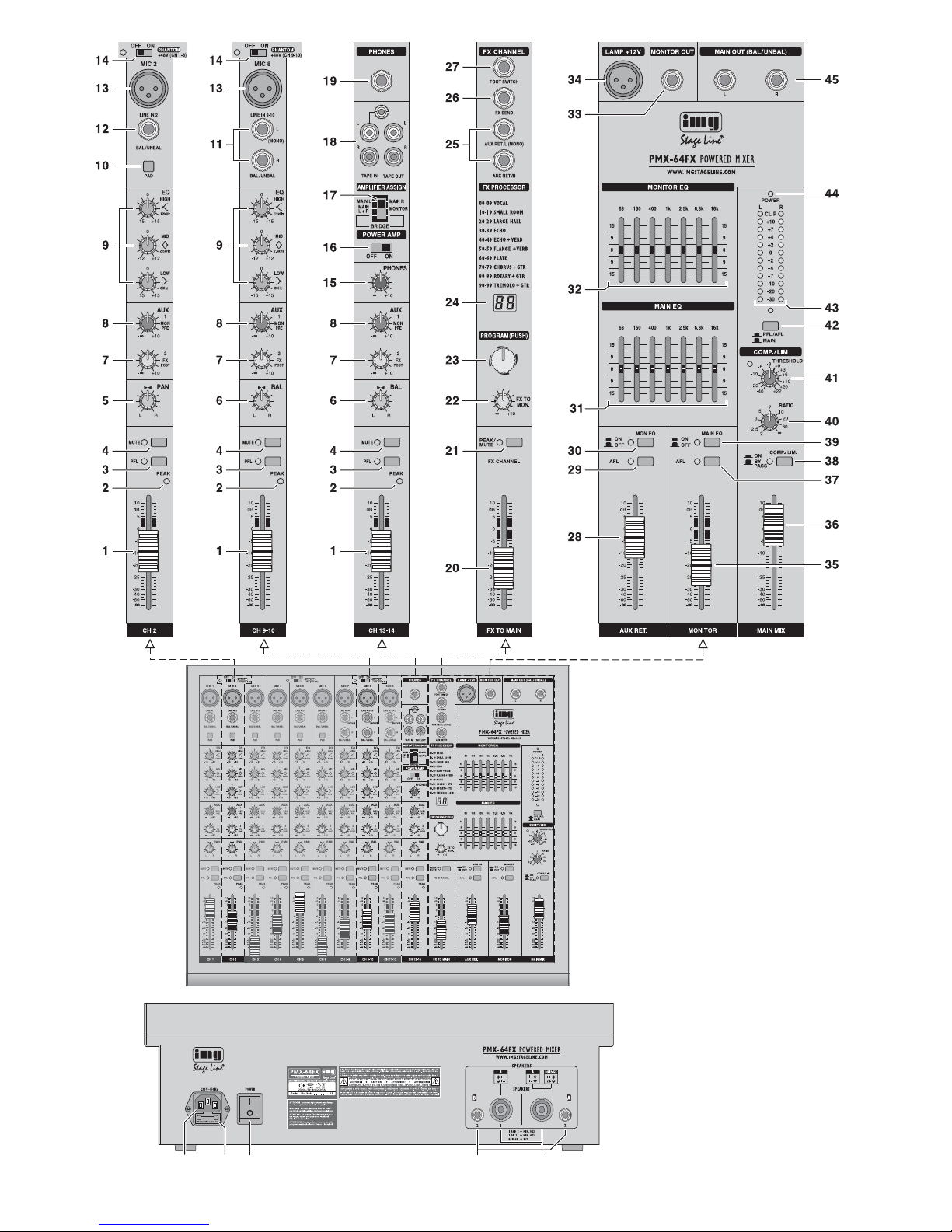
Abb. 1 Mono-Eingangskanal CH 2
Alle Mono-Eingangskanäle (CH 1 …CH 6)
sind identisch.
Abb. 2 Stereo-Eingangskanal CH 9-10
Alle Stereo-Eingangskanäle (CH 7-8,
CH 9-10, CH 11-12) sind identisch.
Abb. 3 Kanal CH 13-14 für ein Aufnahmegerät,
einen Kopfhörer und für die Endstufe
1 Kanalfader für die Kanallautstärke und zum
Ein- und Ausblenden des Kanalsignals
2 LED PEAK zeigt durch kurzes Aufleuchten
an, dass der maximale unverzerrte Signalpegel erreicht ist. Leuchtet sie länger, wird der
Kanal übersteuert. Dann die Taste PAD (10)
hineindrücken oder den Eingangspegel verringern.
3 Taste PFL mit Kontroll-LED zum Vorhören
des gewählten Kanals über einen an der
Buchse PHONES (19) angeschlossenen
Kopfhörer und zum Anzeigen des Kanalsignals durch die Pegelanzeige (43). Dazu muss
auch die Taste (42) unter der Anzeige hineingedrückt sein.
4 Taste MUTE mit Kontroll-LED zum Stumm-
schalten des Kanals
5 Panoramaregler PAN zum Platzieren des
Mono-Signals im Stereo-Klangbild
6 Balanceregler BAL für die Stereokanäle
7 Regler AUX 2 FX zum Mischen des Kanalsig-
nals auf den Ausspielweg AUX 2 (post-fader)
Dieser Ausspielweg dient als Effektweg für
den internen Effektprozessor und für ein
externes Effektgerät.
8 Regler AUX 1MON zum Mischen des Kanal-
signals auf den Ausspielweg AUX 1 (prefader)
Dieser Ausspielweg dient als Monitorweg zur
Beschallung der Musiker.
9 Klangregler
LOW für die Bässe: ±15 dB bei 80Hz
MID für die Mitten: ±12 dB bei 2,5 kHz
HIGH für die Höhen: ±15 dB bei 12kHz
10 Taste PAD zum Verringern des Eingangs -
pegels um 20 dB
11 Stereo-Eingang LINE IN (6,3-mm-Klinken -
buchsen, sym.) für den Anschluss einer Signalquelle mit Line-Ausgangspegel (z. B.
Musikinstrument, CD/ MP3-Spieler)
Hinweis: Beim Anschluss eines Mono-Geräts nur
die Buchse L (MONO) verwenden. Das Signal wird
dann intern auf den rechten und linken Kanal geleitet.
12 Mono-Eingang LINE IN (6,3-mm-Klinkenbuch -
se, sym.) für den Anschluss einer Signalquelle mit Line-Ausgangspegel
13 Eingang MIC für den Anschluss eines Mikro-
fons (XLR-Buchse, sym.)
Für die Mikrofoneingänge lässt sich die Phantomspeisung zuschalten,
Position 14.
14 Ein- /Ausschalter PHANTOM mit Kontroll-
LED für die 48-V-Phantomspeisung von je weils drei Mikrofoneingängen
Beachten Sie bitte die Vorsichtshinweise zur
Phantomspeisung in Kapitel 4.1.1.
15 Lautstärkeregler PHONES für einen an der
Buchse PHONES (19) angeschlossenen
Kopfhörer
16 Ein- /Ausschalter POWER AMP für die End-
stufe
17 Zuordnungsschalter AMPLIFIER ASSIGN für
die Endstufe
obere Position = Die Endstufe arbeitet im
Stereo-Betrieb und verstärkt das linke und
rechte Summensignal.
mittlere Position = Die Endstufe arbeitet im
2-Kanal-Betrieb und verstärkt im Kanal A
das Mono-Summensignal und im Kanal B
das Signal des Ausspielwegs AUX 1 zur
Beschallung der Musiker.
untere Position = Die Endstufe arbeitet im
Brückenbetrieb (doppelte Ausgangsleistung an einem 8-Ω-Lautsprecher) und verstärkt das Mono-Summensignal.
18 Ein- und Ausgangsbuchsen (Cinch) für ein
Aufnahmegerät; als Eingang ist auch eine
3,5-mm-Klinkenbuchse vorhanden
An den Buchsen TAPE OUT liegt das Summensignal nach dem Fader MAIN MIX (36)
an.
Das Signal der Buchsen TAPE IN lässt sich
mit dem Fader CH 13-14 (1) auf das Summensignal mischen.
19 Ausgang PHONES (6,3-mm-Klinkenbuchse)
für den Anschluss eines Stereo-Kopfhörers
(Impedanz min. 8 Ω)
1.2 Effektkanal
20 Fader FX TO MAIN zum Mischen des inter-
nen Effektsignals auf das Summensignal
21 Taste MUTE zum Stummschalten des inter-
nen Effektprozessors
Bei stummgeschaltetem Effektprozessor
leuchtet zur Kontrolle die LED neben der
Taste kontinuierlich. Bei eingeschaltetem
Effektprozessor zeigt die LED Übersteuerungen des Prozessors an.
22 Regler FX TO MON zum Mischen des inter-
nen Effektsignals auf das Signal des Ausspielwegs AUX 1 zur Beschallung der Musiker
23 Knopf PROGRAM zur Effektauswahl: Den
Knopf drehen, bis im Display (24) die Effektnummer blinkend angezeigt wird, dann zur
Bestätigung den Knopf kurz drücken.
24 Display zur Anzeige der gewählten Effekt-
nummer
25 Eingang AUX RET (6,3-mm-Klinkenbuchsen,
sym.), kann als Eingang für ein Effektgerät
oder für eine zusätzliche Line-Tonquelle verwendet werden
Das Eingangssignal wird mit dem Fader AUX
RET (28) auf das Summensignal gemischt.
Hinweis: Beim Anschluss eines Mono-Geräts nur
die Buchse L (MONO) verwenden. Das Signal wird
dann intern auf den rechten und linken Kanal ge leitet.
26 Ausgang FX SEND (6,3-mm-Klinkenbuchse,
asym.) für den Effekt-Ausspielweg AUX 2
27 Anschluss FOOT SWITCH (6,3-mm-Klinken -
buchse, 2-polig) für einen Fußtaster zum Ein-/
Ausschalten des internen Effektprozessors
Deutsch

5
1.3 Ausgangsfeld
28 Fader AUX RET zum Mischen des Signals
am Eingang AUX RET (25) auf das Summensignal
29 Taste AFL mit Kontroll-LED zum Abhören des
Signals vom Eingang AUX RET (25) nach
dem Fader AUX RET (28) über einen an der
Buchse PHONES (19) angeschlossenen
Kopfhörer. Zum Anzeigen des Signals durch
die Pegelanzeige (43) muss auch die Taste
(42) unter der Anzeige hineingedrückt sein.
30 Taste MON EQ mit Kontroll-LED zum Ein-
schalten des Equalizers für das Signal des
Ausspielwegs AUX 1 zur Beschallung der
Musiker
31 7-Band-Equalizer für das Summensignal
32 7-Band-Equalizer für das Signal des Aus-
spielwegs AUX 1 zur Beschallung der Musiker
33 Line-Ausgang MONITOR OUT (6,3-mm-
Klinkenbuchse, asym.) für das Signal des
Ausspielwegs AUX 1 zur Beschallung der
Musiker
34 XLR-Buchse LAMP zum Hineinstecken einer
Schwanenhalslampe für die Pultbeleuchtung
(12 V /500 mA max.)
35 Fader MONITOR für den Pegel des Monitor-
signals am Ausgang MONITOR OUT (33)
und für die Lautstärke des Monitorsignals,
wenn es auf die Endstufe gegeben wird
[Schalter AMPLIFIER ASSIGN (17) in der
mittleren Position]
36 Fader MAIN MIX für den Pegel des Sum-
mensignals am Ausgang MAIN OUT (45) und
für die Lautstärke des Summensignals, das
auf die Endstufe gegeben wird
37 Taste AFL mit Kontroll-LED zum Abhören
des Monitorsignals nach dem Fader MONITOR (35) über einen an der Buchse
PHONES (19) angeschlossenen Kopfhörer.
Zum Anzeigen des Signals durch die Pegelanzeige (43) muss auch die Taste (42) unter
der Anzeige hineingedrückt sein.
38 Taste COMP/ LIM mit Kontroll-LED zum Ein-
schalten des Kompressors für das Summensignal
39 Taste MAIN EQ mit Kontroll-LED zum Ein-
schalten des Equalizers für das Summen signal
40 Regler RATIO zum Einstellen des Kompres-
sionsverhältnisses
41 Regler THRESHOLD zum Einstellen des Ein-
satzpunktes (Schwellwert), ab dem das Summensignal komprimiert werden soll
42 Taste PFL /AFL – MAIN mit Kontroll-LED zur
Auswahl des Signals, das die Pegelanzeige
(43) anzeigen und das auf den Kopfhörerausgang PHONES (19) gegeben werden soll
Taste ausgerastet:
Das Summensignal nach dem Fader MAIN
MIX (36) wird angezeigt und auf den Kopfhörerausgang gegeben.
Taste hineingedrückt:
Das Signal eines Kanals, dessen Taste
PFL (3) oder AFL (29, 37) gedrückt ist, wird
angezeigt und auf den Kopfhörerausgang
gegeben.
43 Pegelanzeige; zeigt den Pegel des Signals
an, das zum Abhören über den Kopfhörerausgang PHONES (19) gewählt ist, siehe
Position 42
44 Betriebsanzeige POWER
45 Line-Ausgang MAIN OUT für das Summen-
signal (6,3-mm-Klinkenbuchsen, sym.)
1.4 Rückseite
46 Netzbuchse zum Anschluss an eine Steck-
dose (230 V~ / 50 Hz) über das beiliegende
Netzkabel
47 Halterung für die Netzsicherung
Eine geschmolzene Sicherung nur durch
eine gleichen Typs ersetzen.
48 Ein- /Ausschalter POWER
49 Lautsprecherbuchsen (6,3-mm-Klinke)
alternativ zu den Anschlüssen (50)
50 Lautsprecherbuchsen (SPEAKON
®
-kompatibel) alternativ zu den 6,3-mm-Klinken buch sen (49)
2 Hinweise für den
sicheren Gebrauch
Das Gerät entspricht allen relevanten Richtlinien
der EU und ist deshalb mit gekennzeichnet.
Beachten Sie auch unbedingt folgende Punkte:
G
Verwenden Sie das Gerät nur im Innenbereich
und schützen Sie es vor Tropf- und Spritzwasser, hoher Luftfeuchtigkeit und Hitze (zulässiger Einsatztemperaturbereich 0 – 40 °C).
G
Stellen Sie keine mit Flüssigkeit gefüllten Ge fäße z. B. Trinkgläser, auf das Gerät.
G
Die in dem Gerät entstehende Wärme muss
durch Luftzirkulation abgegeben werden.
Decken Sie darum die Lüftungsöffnungen des
Gehäuses nicht ab.
G
Nehmen Sie das Gerät nicht in Betrieb und
ziehen Sie sofort den Netzstecker aus der
Steckdose,
1. wenn sichtbare Schäden am Gerät oder am
Netzkabel vorhanden sind,
2. wenn nach einem Sturz oder Ähnlichem der
Verdacht auf einen Defekt besteht,
3. wenn Funktionsstörungen auftreten.
Geben Sie das Gerät in jedem Fall zur Reparatur in eine Fachwerkstatt.
G
Ziehen Sie den Netzstecker nie am Kabel aus
der Steckdose, fassen Sie immer am Stecker
an.
G
Verwenden Sie für die Reinigung nur ein trockenes, weiches Tuch, niemals Wasser oder
Chemikalien.
G
Wird das Gerät zweckentfremdet, nicht richtig
angeschlossen, falsch be dient oder nicht fachgerecht repariert, kann keine Haftung für
daraus resultierende Sach- oder Personenschäden und keine Garantie für das Gerät
übernommen werden.
3 Einsatzmöglichkeiten
Dieses Audio-Mischpult mit integrierter StereoEndstufe (Klasse D, 2 × 475 W
RMS an 4-Ω-Laut -
sprechern) ist für vielfältige Beschallungs- und
Aufnahmezwecke geeignet. Es ist als Tischgerät
ausgelegt und verfügt über 6 Mono- und 3 Stereo-Eingangskanäle zum Anschluss von Mikro-
fonen (auch phantomgespeisten) und Tonquellen mit Line-Ausgangspegel (z. B. Instrumente,
Abspielgeräte). Ein weiterer Stereo-Eingangskanal kann z. B. für die Wiedergabe eines Aufnahmegerätes genutzt werden.
Die Eingangssignale lassen sich auf einen
Stereo-Summenkanal und auf zwei Ausspielwege mischen. Zum Zumischen von Effekten ist
ein digitaler Effektprozessor vorhanden. Die
Tonmischung lässt sich über einen Kopfhörer
abhören. Außerdem können einzelne Kanalsignale über den Kopfhörer vorgehört werden.
4 Geräte anschließen
Um Störgeräusche zu vermeiden, vor dem Herstellen/Trennen von Verbindungen das Mischpult ausschalten oder die Fader MONITOR (35)
und MAIN MIX (36) ganz zuziehen sowie den
Regler PHONES (15) ganz zudrehen.
4.1 Tonquellen
In den Eingangskanälen kann nicht zwischen dem
Mikrofoneingang (13) und dem Line-Eingang
(11, 12) umgeschaltet werden. Darum pro Kanal
nur einen von beiden Eingängen anschließen.
4.1.1 Mikrofone
Mikrofone an die symmetrisch beschalteten
XLR-Buchsen MIC (13) anschließen. Für phantomgespeiste Mikrofone lässt sich für jeweils
drei Mikrofoneingänge mit den Schaltern PHANTOM (14) eine 48-V-Phantomspeisung einschalten. Bei aktivierter Phantomspeisung leuchtet
die LED neben dem Schalter.
4.1.2 Line-Tonquellen
Tonquellen mit Line-Signalpegel (z. B. Empfänger von drahtlosen Mikrofonsystemen, Effektgeräte, Instrumente, Abspielgeräte) an die 6,3-mmKlinkenbuchsen LINE IN (11, 12) der Eingangskanäle anschließen. Die Buchsen sind symmetrisch be schaltet. Es lassen sich aber auch Geräte mit asymmetrisch beschaltetem Ausgang über
zweipolige Klinkenstecker anschließen.
— Mono-Geräte an die Buchsen (12) der Mono-
Kanäle CH 1 bis CH 6 anschließen.
— Stereo-Geräte an die Buchsen (11) der Ste-
reo-Kanäle CH 7-8, CH 9-10 und CH 11-12
anschließen. Soll an einen Stereo-Kanal ein
Mono-Gerät angeschlossen werden, nur die
obere Buchse L (MONO) verwenden. Das
Mono-Signal wird dann intern auf den rechten und linken Kanal geleitet.
Reichen die Eingangskanäle nicht aus, können
zum Anschluss von zusätzlichen Line-Quellen
auch folgende Stereo-Eingänge genutzt werden:
1. der Eingang AUX RET (25)
Beim Anschluss eines Mono-Geräts nur die
Buchse L (MONO) verwenden, das MonoSignal wird dann intern auf den linken und
rechten Kanal geleitet.
2. der Eingang TAPE IN (18)
z. B. zum Anschluss eines CD-Spielers für
Hintergrundmusik in den Spielpausen
Vorsicht: Bei eingeschalteter Phantomspeisung darf kein Mikrofon mit asymmetrischem
Ausgang angeschlossen sein, da dieses be schädigt werden kann.
Um Schaltgeräusche in den Lautsprechern und
im Kopfhörer zu vermeiden, die Phantomspeisung nur ein- oder ausschalten, wenn das
Mischpult ausgeschaltet ist oder die zugehörigen Tasten MUTE (4) hineingedrückt sind und
der Regler PHONES (15) zugedreht ist.
Soll das Gerät endgültig aus dem
Betrieb genommen werden, übergeben
Sie es zur umweltgerechten Entsorgung einem örtlichen Recyclingbetrieb.
WARNUNG Dieses Gerät wird mit lebensge-
fährlicher Netzspannung versorgt.
Nehmen Sie deshalb nie selbst
Eingriffe am Gerät vor und stecken
Sie nichts durch die Lüftungsöffnungen. Es besteht die Gefahr
eines elektrischen Schlages.
Deutsch

6
4.2 Effektgerät
Über den Ausspielweg AUX 2, der gleichzeitig
als Effektweg für den internen Effektprozessor
dient, können Signalanteile aus den Eingangskanälen ausgekoppelt, über ein Effektgerät (z. B.
Hallgerät) bearbeitet und über die Return-Eingänge wieder in das Mischpult zurückgeführt
werden. Der Signalabgriff für diesen Ausspielweg ist post-fader, d. h. das Kanalsignal wird
nach dem Fader (1) auf den Ausspielweg
gemischt. Auf diese Weise ist der Effektanteil
eines Kanals immer proportional zum eingestellten Kanalpegel.
1) Den Eingang des Effektgerätes über einen
6,3-mm-Klinkenstecker an den Mono-Ausgang FX SEND (26) anschließen.
2) Das vom Effektgerät kommende Signal auf
den Eingang AUX RET (25) zurückführen.
Hinweis: Beim Anschluss eines Mono-Geräts nur
die Buchse L (MONO) verwenden. Das Signal wird
dann intern auf den rechten und linken Kanal ge leitet.
3) Alternativ kann das Signal vom Effektgerät
auch auf den Line-Eingang eines freien Eingangskanals gegeben werden.
Soll das Effektsignal auch auf den Monitorweg AUX 1 gemischt werden, muss unbedingt ein freier Eingangskanal benutzt werden, weil dieses nur mit den Regler AUX 1
MON (8) erfolgen kann.
4.3 Aufnahmegerät
Ein Aufnahmegerät kann an die Buchsen TAPE
IN und TAPE OUT (18) angeschlossen werden
(L = linker Kanal, R = rechter Kanal):
1) Für Aufnahmen den Eingang des Gerätes an
die Cinch-Buchsen TAPE OUT anschließen.
Hier liegt das mit dem Fader MAIN MIX (36)
eingestellte Summensignal an.
2) Für die Wiedergabe den Ausgang des Gerätes an die Cinch-Buchsen oder an die 3,5-mmKlinkenbuchse TAPE IN anschließen. Das
Signal der Buchsen TAPE IN lässt sich mit
dem Fader des Kanals CH 13-14 (1) auf das
Summensignal mischen.
4.4 Kopfhörer
Über einen Kopfhörer lassen sich folgende Signale abhören:
– die Signale der einzelnen Eingangskanäle
– das Summensignal
– das Signal des Ausspielwegs AUX 1
– das Eingangssignal der Buchsen AUX RET (25)
Den Kopfhörer (Mindestimpedanz 8 Ω) an die
Buchse PHONES (19) anschließen.
4.5 Monitoranlage für die Musiker
Beim Einsatz einer Monitoranlage für die Bühnenbeschallung lässt sich der Ausspielweg
AUX 1 als Monitorweg nutzen. Der Signalabgriff
für diesen Ausspielweg ist pre-fader, d. h. das
Kanalsignal wird vor dem Fader (1) auf den Ausspielweg gemischt. So erhalten die Musiker über
die Bühnenlautsprecher ein separat abgemischtes Musiksignal.
Den Verstärker der Monitoranlage oder eine
aktive Monitorbox mit der Buchse MONITOR
OUT (33) verbinden. Alternativ kann auch ein
Kanal der internen Endstufe das Monitorsignal
verstärken, wenn die Saalbeschallung nur
monofon über den anderen Kanal erfolgen soll.
Dazu den Schalter AMPLIFIER ASSIGN (17) in
die mittlere Position schieben. Zum Anschluss
der Lautsprecher siehe Kapitel 4.7.
4.6 Zusätzlicher Verstärker
Für die Beschallung des Publikums kann die
interne Endstufe verwendet werden. Reicht
diese nicht aus oder soll das Summensignal z. B.
in einem weiteren Raum zu hören sein, einen
zusätzlichen Verstärker an den Ausgang MAIN
OUT (45) anschließen. Hier liegt das mit dem
Fader MAIN MIX (36) eingestellte Summensignal an. Alternativ oder zusätzlich können hierfür
auch die Cinch-Buchsen TAPE OUT (18) verwendet werden.
4.7 Lautsprecher
Für den Anschluss der Lautsprecher können die
Klinkenbuchsen (49) oder die SPEAKON®-kompatiblen Buchsen (50) verwendet werden. Werden die SPEAKON
®
-kompatiblen Buchsen ge nutzt, den jeweiligen Lautsprecherstecker nach
dem Einstecken in die Buchse nach rechts drehen, bis er einrastet. Zum späteren Herausziehen den Sicherungsriegel am Stecker zurückziehen und den Stecker nach links drehen.
Der korrekte Anschluss der Lautsprecher
richtet sich nach der gewünschten Betriebsart
für die Endstufe, die mit dem Schalter AMPFLIFIER ASSIGN (17) eingestellt wird:
Stereobetrieb (obere Schalterposition)
Die Endstufe verstärkt das Stereo-Summensignal. Die Lautsprecher (Impedanz min. 4 Ω) an
die Buchse A (linker Kanal) und an die Buchse B
(rechter Kanal) anschließen.
2-Kanal-Betrieb (mittlere Schalterposition)
Die Endstufe verstärkt im Kanal A das MonoSummensignal und im Kanal B das Signal des
Ausspielwegs AUX 1 zur Beschallung der Musiker. Den Lautsprecher (Impedanz min. 4 Ω) für
die Beschallung des Publikums an die Buchse A
anschließen und den Lautsprecher (Impedanz
min. 4 Ω) für die Beschallung der Musiker an die
Buchse B.
Brückenbetrieb (untere Schalterposition)
Die Endstufe verstärkt das Mono-Summensignal
mit der doppelten Leistung. Der Lautsprecher
(Impedanz min. 8Ω) oder eine Lautsprecher-
gruppe mit einer Gesamtimpedanz von 8 Ω kann
nur an die SPEAKON
®-
kompatible Buchse A
wie folgt an geschlossen werden:
Kontakt 1+ für den Pluspol
Kontakt 2+ für den Minuspol
Abb. 8 SPEAKON®-kompatibler Stecker
Anschluss für den Brückenbetrieb
4.8 Pultleuchte
Um das Mischpult zu beleuchten, lässt sich in
die XLR-Buchse LAMP (34) eine Schwanenhalsleuchte (12 V/500 mA max.) stecken, z.B. das
Modell GNL-304, GNL-305 oder GNL-314 von
„img Stage Line“. Die Leuchte wird zusammen
mit dem Mischpult ein- und ausgeschaltet.
4.9 Fußtaster für den Effektprozessor
Um den internen Effektprozessor z. B. von der
Bühne aus ein- und ausschalten zu können,
lässt sich ein Fußtaster (z. B. FS-60 von
MONACOR) an die zweipolige 6,3-mm-Klinken buchse FOOT SWITCH (27) anschließen.
4.10 Stromversorgung
Das Mischpult über die Netzbuchse (46) mit
dem beiliegenden Netzkabel an eine Steckdose
(230 V~ / 50 Hz) anschließen.
5 Bedienung
5.1 Ein- und Ausschalten
1) Um Einschaltgeräusche und eine zu hohe
Lautstärke zu vermeiden, vor der Inbetriebnahme die Fader MONITOR (35) und MAIN
MIX (36) ganz zuziehen sowie den Regler
PHONES (15) ganz zudrehen.
2) Je nachdem welcher Mikrofontyp angeschlossen ist, die 48-V-Phantomspeisung mit
den Schaltern PHANTOM (14) entweder einoder ausschalten (Kapitel 4.1.1).
3) Wird die interne Endstufe verwendet, die korrekte Stellung des Schalters AMPFLIFIER
ASSIGN (17) überprüfen (Kapitel 4.7)
und die Endstufe mit dem Schalter POWER
AMP (16) einschalten. Wird die Endstufe
nicht verwendet, die Endstufe ausschalten.
4) Zum Ein- und Ausschalten des Mischpults
den Netzschalter POWER (48) betätigen. Bei
eingeschaltetem Gerät leuchten die Betriebsanzeige POWER (44) und das Display (24).
5.2 Eingangssignale mischen
Die folgenden Bedienschritte dienen nur als
Hilfestellung, es sind auch andere Vorgehensweisen möglich.
1) Zuerst folgende Grundeinstellung vornehmen.
a) Alle Tasten PAD (10) ausrasten.
b) Alle Klangregler HIGH, MID, LOW (9) und
alle Schieberegler der Equalizer (31, 32)
in die Mittelposition stellen.
c) Alle Regler AUX 1MON (8) und AUX2FX
(7) für die Ausspielwege ganz zudrehen.
d) Alle Panoramaregler PAN (5) und alle
Balanceregler BAL (6) in die Mitte drehen.
e) Den Regler FX TO MON (22) ganz zudre-
hen.
f) Alle Tasten MUTE (4), PFL (3), AFL (29,
37) sowie die Tasten COMP/ LIM (38) und
PFL /AFL – MAIN (42) ausrasten.
g) Alle Kanalfader (1) sowie die Fader FX TO
MAIN (20) und AUX RET (28) zuziehen.
2) Auf den Kanal, der am lautesten zu hören
sein soll, ein Signal geben (z. B. in ein Mikrofon singen, ein Instrument spielen) und den
zugehörigen Fader (1) vorerst ca. auf die
Position 0 dB aufziehen.
Der Kanal ist optimal ausgesteuert, wenn
bei Signalspitzen die LED PEAK (2) kurz aufleuchtet. Leuchtet sie länger, wird der Kanal
übersteuert. Dann das Eingangssignal mit
der Taste PAD (10) abschwächen oder den
Ausgangspegel der Signalquelle verringern.
3) Den Fader MAIN MIX (36) so weit aufziehen,
dass die folgenden Einstellungen gut über die
an geschlossenen Lautsprecher zu hören
sind oder über einen an der Buchse PHONES
(19) angeschlossenen Kopfhörer. Die Kopfhörerlautstärke zusätzlich mit dem Regler
PHONES (15) einstellen.
4) Den Klang des Kanalsignals mit den Reglern
HIGH, MID und LOW (9) einstellen.
1+ =2
-
1
-
2+ =
VORSICHT Stellen Sie die Lautstärke der
Lautsprecher und des Kopfhörers
nie sehr hoch ein. Hohe Lautstärken können auf Dauer das Gehör
schädigen! Das Ohr gewöhnt sich
an hohe Lautstärken und empfindet sie nach einiger Zeit als nicht
mehr so hoch. Erhöhen Sie darum
eine hohe Lautstärke nach der
Gewöhnung nicht weiter.
Deutsch
7
5) Bei einem Mono-Kanal mit dem Panoramaregler PAN (5) das Mono-Signal im StereoKlangbild platzieren oder bei einem StereoKanal mit dem Regler BAL (6) die Balance
des Stereo-Signals einstellen.
6) Schrittweise alle weiteren Kanalsignale da zumischen und jeweils den Klang einstellen
sowie die Panorama- oder Balanceeinstellung vornehmen. Die Fader nicht benutzter
Kanäle immer ganz zuziehen.
Tipps
1. Kann ein Kanalfader beim Dazumischen eines
Signals nur gering aufgezogen werden, weil der
Eingangspegel sehr groß ist, die zugehörige
Taste PAD drücken oder den Ausgangspegel der
Signalquelle verringern. Dadurch kann ein längerer Faderweg für eine feinere Einstellung genutzt
werden.
2. Bei der Klangeinstellung kann es hilfreich sein,
andere Kanäle zeitweise mit der MUTE-Taste (4)
stummzuschalten. Zur Kontrolle leuchtet die LED
neben der Taste. Ein einzelner Kanal lässt sich
aber auch optimal über einen Kopfhörer abhören
und einstellen (
Kapitel 5.6).
7) Zum Zumischen von Effekten siehe Kap. 5.5.
8) Das Eingangssignal der Buchsen TAPE IN
(18) lässt sich mit dem Fader (1) des Kanals
CH 13-14 auf die Signalsumme mischen.
Hinweis: Wird während einer Aufnahme über die
Buchsen TAPE OUT das Aufnahmesignal als Eingangssignal auf die Buchsen TAPE IN gegeben, die
Taste MUTE des Kanals CH 13-14 hineindrücken,
damit keine Rückkopplung auftritt.
9) Die endgültige Lautstärke des Summensignals mit dem Fader MAIN MIX einstellen. Das
Signal kann mit der Pegelanzeige (43) kontrolliert werden, wenn die Taste PFL /AFL –
MAIN unter der Anzeige nicht hineingedrückt
ist. Bei Übersteuerung leuchten die roten
LEDs CLIP auf; den Fader MAIN MIX dann
entsprechend zurückziehen.
10) Der Klang des Summensignals lässt sich mit
dem 7-Band-Equalizer MAIN EQ an die
Raumakustik anpassen. Dazu den Equalizer
mit der Taste MAIN EQ (39) einschalten und
den Klang mit den Schiebereglern (31) einstellen.
Hinweis: Das Signal am Ausgang TAPE OUT (18)
wird ebenfalls durch den Equalizer beeinflusst. Bei
einer Aufnahme den Equalizer mit der Taste MAIN
EQ ggf. ausschalten.
11) Zum Stummschalten eines Kanals, z. B. während einer Spielpause, die zugehörige Taste
MUTE drücken.
5.3 Signalkompressor verwenden
Die Dynamik des Summensignals lässt sich
durch den integrierten Kompressor reduzieren.
Er schwächt den Pegel oberhalb einer einstellbaren Schwelle ab. Dies ist z. B. erforderlich,
wenn die Dynamik des Audiosignals größer ist
als das Aufnahme- oder Verstärkersystem
erlaubt oder eine geringe Dynamik (z. B. für Hintergrundmusik) erwünscht ist. Auch lassen sich
Signalspitzen ab schwächen, um eine höhere
Aussteuerbarkeit und damit eine höhere Durchschnittslautstärke zu erreichen.
1) Den Kompressor mit der Taste COMP/ LIM
(38) einschalten. Die LED neben der Taste
leuchtet.
2) Den Einsatzpunkt (Schwellwert) der Kompression mit dem Regler THRESHOLD (41)
einstellen. Das Kompressionsverhältnis mit
dem Regler RATIO (40) einstellen:
Position „4“:
Das Verhältnis beträgt 4 : 1; eine Eingangspegeländerung von 8 dB oberhalb des Thresh old-Wertes bewirkt eine Ausgangspegeländerung von 2 dB.
Position „∞“:
Der Kompressor arbeitet als Signalbegrenzer
(Limiter); das Ausgangssignal wird etwa auf
den mit dem Regler THRESHOLD eingestellten Wert begrenzt.
Tipp: Je höher der Schwellwert und je niedriger das
Kompressionsverhältnis eingestellt wird, desto
mehr bleibt die natürliche Dynamik erhalten.
3) Die LED neben dem Regler THRESHOLD
leuchtet auf, wenn das Eingangssignal des
Kompressors den eingestellten Schwellwert
überschreitet und das Ausgangssignal komprimiert wird. Die Pegelanzeige (43) kann
ebenfalls als Einstellhilfe dienen. Um den
Ausgangspegel ablesen zu können, die
Taste PFL /AFL – MAIN (42) unter der An zeige ausrasten.
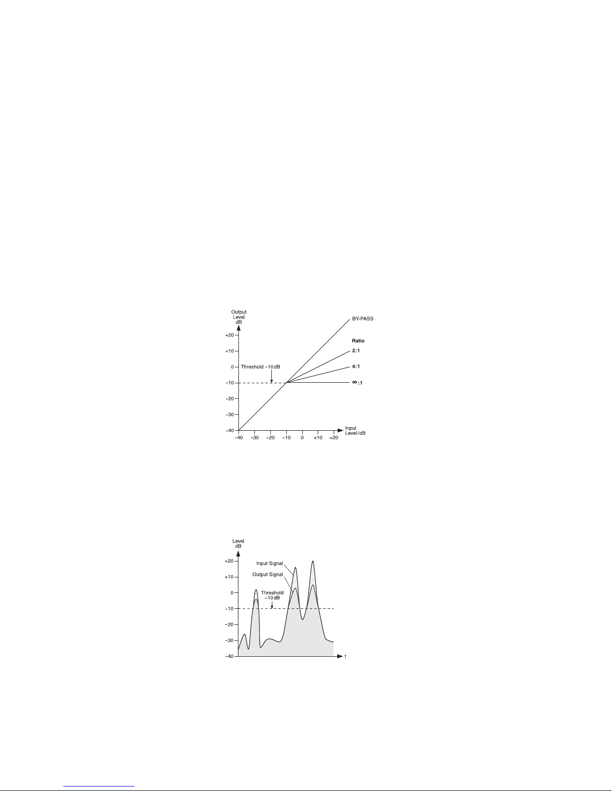
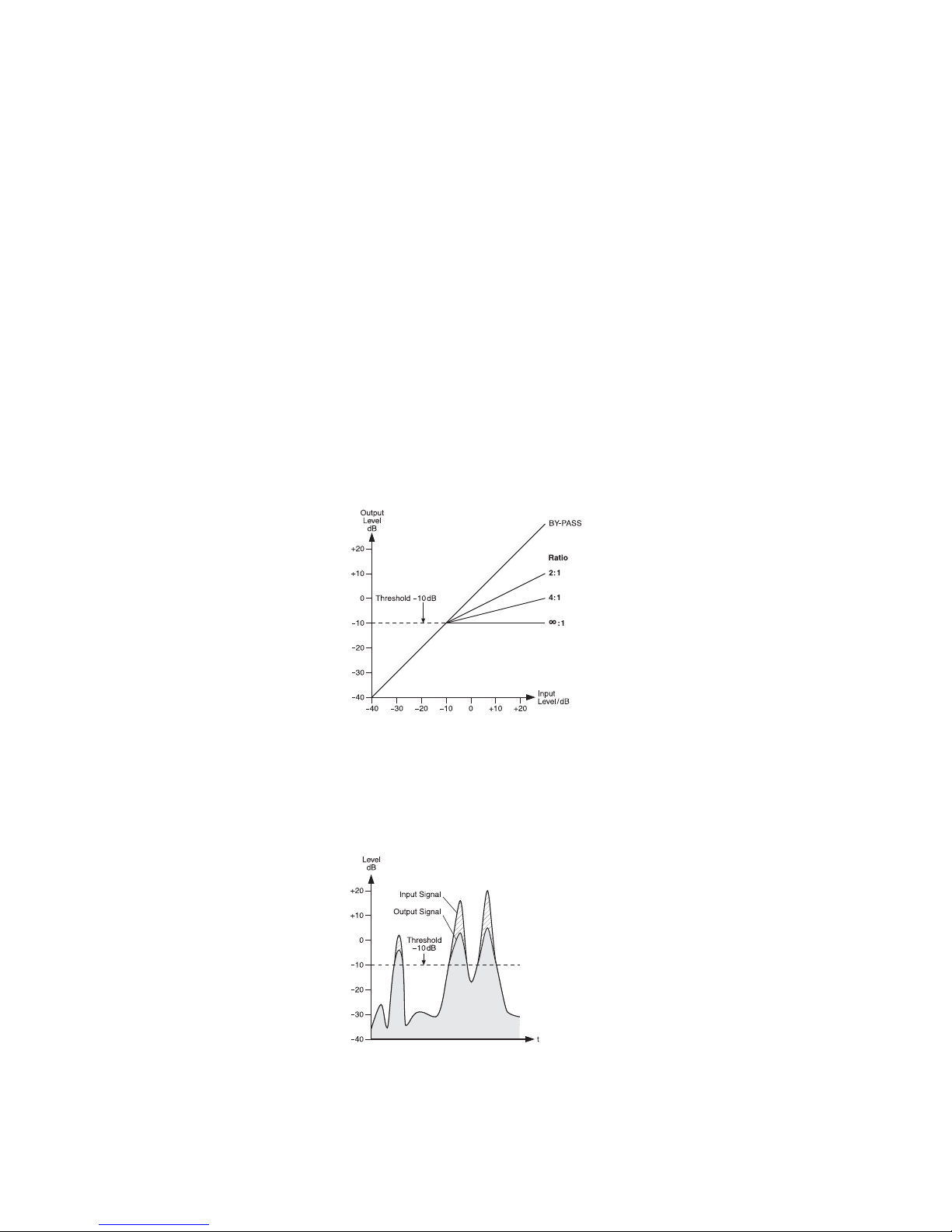
Die Abbildung 9 zeigt als Beispiel den Ausgangspegel in Abhängigkeit vom Eingangspegel bei einem Schwellwert von
-
10 dB und
verschiedenen Kompressionsverhältnissen.
Abb. 9 Steuerkennlinien des Kompressors
bei einem Schwellwert von
-
10 dB
Die Abbildung 10 zeigt ein Eingangssignal
und das resultierende Ausgangssignal bei
einem Schwellwert von
-
10 dB und einem
Kompressionsverhältnis von 2 : 1. Unterhalb
des Schwellwertes bleibt das Signal unverändert und oberhalb wird es um den Faktor 2
komprimiert.
Abb. 10 Ein- und Ausgangssignal des Kompressors
bei einem Schwellwert von
-
10 dB und
einem Kompressionsverhältnis von 2 :1
5.4 Monitor-Ausspielweg einstellen
1) Den Fader MONITOR (35) für die Lautstärke
der Monitormischung so weit aufziehen, dass
das Monitorsignal für die folgenden Einstellungen gut über die Monitoranlage oder über
die angeschlossenen Lautsprecher zu hören
ist.
2) Mit den Reglern AUX 1 MON (8) die Kanalsignale auf den Monitorweg mischen: Die
Regler je nach gewünschtem Lautstärkeverhältnis der Kanäle aufdrehen. In den zuge hörigen Eingangskanälen muss die Taste
MUTE (4) ausgerastet sein.
3) Mit dem Regler FX TO MON (22) lässt sich
das Effektsignal des internen Effektprozessors (
Kap. 5.5.1) auf den Monitorweg
mischen.
4) Die endgültige Lautstärke des Monitorsignals
mit dem Fader MONITOR einstellen.
5) Der Klang des Monitorsignals lässt sich mit
dem 7-Band-Equalizer MONITOR EQ optimieren. Dazu den Equalizer mit der Taste
MON EQ (30) einschalten und den Klang mit
den Schiebereglern einstellen (32).
6) Soll der Monitorweg über einen Kopfhörer ab gehört werden und die Pegelanzeige (43) das
Monitorsignal anzeigen, die Taste AFL (37)
über dem Fader MONITOR und die Taste
PFL /AFL – MAIN (42) unter der Anzeige hin eindrücken (
Kap. 5.6).
Deutsch

8
5.5 Effekte zumischen
5.5.1 Verwendung des internen
Effektprozessors
Mit dem internen Effektprozessor lassen sich
100 verschiedene Effekte erzeugen, die auf das
Summensignal und auf den Monitor-Ausspielweg AUX 1 gemischt werden können. Als Effektweg für den Effektprozessor dient der Ausspielweg AUX 2.
1) Damit die Effekteinstellungen zu hören sind,
den Fader FX TO MAIN (20) vorerst ungefähr
in die Mittelposition schieben.
2) Den Drehknopf PROGRAM (23) links- oder
rechtsherum drehen, bis die Nummer des
gewünschten Effekts (
Abb. 11 Effektübersicht) blinkend im Display (24) angezeigt
wird. Die Wahl durch Drücken des Knopfes
bestätigen: Die Nummer hört auf zu blinken,
der Effekt ist eingeschaltet.
3) Mit den Reglern AUX 2 FX (7) die Signale der
Eingangskanäle auf den Effektweg mischen.
Mit diesen Reglern lässt sich für jeden Kanal
getrennt die gewünschte Effektintensität einstellen. Der Signalabgriff ist nach dem Fader
(1), d. h. der Effektanteil eines Kanals ist
immer proportional zum eingestellten Kanalpegel.
4) Die LED PEAK / MUTE über dem Fader FX TO
MAIN neben der Taste MUTE (21) dient bei
eingeschaltetem Effektprozessor als Übersteuerungsanzeige. Mit ihr lässt sich die Aussteuerung grob kontrollieren. Leuchtet sie
auf, die Regler AUX 2 FX entsprechend zu rückdrehen.
5) Das Effektsignal mit dem Fader FX TO MAIN
auf die Summenkanäle mischen und wenn
gewünscht, mit dem Regler FX TO MON (22)
auch auf den Ausspielweg AUX 1.
6) Der Effektprozessor lässt sich mit einem an
der Buchse FOOT SWITCH (27) angeschlossenen Fußtaster und mit der Taste MUTE
(21) aus- und wieder einschalten (die Taste
rastet nicht ein). Ist er ausgeschaltet, leuchtet
zur Kontrolle die LED PEAK / MUTE neben
der Taste MUTE.
5.5.2 Externes Effektgerät
Das Effektgerät muss über den Ausgang FX
SEND (26) und den Eingang AUX RET (25) oder
den Line-Eingang eines freien Eingangskanals
angeschlossen sein,
Kapitel 4.2.
1) Damit die Effekteinstellungen zu hören sind,
den Fader AUX RET (28) vorerst ungefähr in
die Mittelposition schieben. Oder, wenn ein
freier Eingangskanal als Effekteingang be nutzt wird, den zugehörigen Kanalfader (1)
ungefähr in die Mittelposition schieben.
2) Am Effektgerät den gewünschten Effekt einschalten.
3) Mit den Reglern AUX 2 FX (7) die Signale der
Eingangskanäle auf den Effektweg mischen.
Mit diesen Reglern lässt sich für jeden Kanal
getrennt die gewünschte Effektintensität einstellen. Der Signalabgriff ist nach dem Fader
(1), d. h. der Effektanteil eines Kanals ist
immer proportional zum eingestellten Kanalpegel.
Hinweise
1. Ist das Effektgerät am Line-Eingang eines Ein-
gangskanals angeschlossen, den Regler AUX 2
FX des betreffenden Kanals ganz zudrehen,
sonst tritt eine Rückkopplung auf.
2. Die Signale des Effektwegs werden auch auf den
Eingang des internen Effektprozessors gegeben
(
Kap. 5.5.1). Deshalb je nach Bedarf die
Intensität des internen Effekts separat mit dem
Regler FX TO MAIN (20) einstellen oder den
internen Effekt mit der Taste MUTE (21) stummschalten.
4) Das vom Effektgerät kommende Signal mit
dem jeweiligen Eingangsregler zumischen;
mit ihm lässt sich die Effektintensität für alle
Kanäle gemeinsam einstellen:
— Ist das Effektgerät am Eingang AUX RET
(25) angeschlossen, das Effektsignal mit
dem Regler AUX RET (28) auf das Summensignal mischen.
— Ist das Effektgerät am Line-Eingang (11,
12) eines Eingangskanals angeschlossen,
das Effektsignal mit dem entsprechenden
Kanalfader (1) auf das Summensignal
mischen. Wenn gewünscht, kann das
Effektsignal mit dem zugehörigen Regler
AUX 1 MON (8) auch auf den Monitorausspielweg AUX 1 gemischt werden.
5.6 Abhören über einen Kopfhörer
Zum Abhören über einen Kopfhörer an der
Buchse PHONES (19) lassen sich folgende Signale anwählen:
1. das Summensignal post-fader, d. h. nach dem
Fader MAIN MIX (36)
2. die Signale der einzelnen Eingangskanäle
pre-fader, d. h. vor dem Kanalfader (1), der
Taste MUTE (4) und dem Regler PAN (5)
oder BAL (6)
3. das Signal des Ausspielwegs AUX 1 postfader, d. h. nach dem Fader MONITOR (35)
4. das Eingangssignal der Buchsen AUX RET
(25) post-fader, d. h. nach dem Fader AUX
RET (28)
Die Pegelanzeige (43) zeigt immer das Signal
an, welches zum Abhören ausgewählt ist.
1) Zum Abhören des Summensignals die
Taste PFL /AFL – MAIN (42) unter der Pegelanzeige ausrasten. Die LED über der Taste
darf nicht leuchten.
2) Zum Abhören eines Eingangskanals die
Taste PFL (3) des Kanals drücken. Zur Kontrolle leuchtet die LED neben der Taste.
Zusätzlich die Taste PFL /AFL – MAIN (42)
unter der Pegelanzeige hineindrücken. Die
LED über der Taste leuchtet.
3) Zum Abhören des Ausspielwegs AUX 1 für
die Beschallung der Musiker die Taste AFL
(37) über dem Fader MONITOR (35) drücken. Zusätzlich muss die Taste PFL /AFL –
MAIN unter der Pegelanzeige hineingedrückt
sein.
4) Zum Abhören des Eingangssignals der
Buchsen AUX RET die Taste AFL (29) über
dem Fader AUX RET (28) drücken. Zusätzlich muss die Taste PFL /AFL – MAIN unter
der Pegelanzeige hineingedrückt sein.
Deutsch
Nummer Name Effekt Parameter
00 – 09 Vocal Nachhalleffekt, besonders für Gesangsanwendungen geeignet Abklingzeit 0,8 – 0,9 s, Pre-Delay-Zeit 10 – 45ms
10 – 19 Small Room Nachhalleffekt: Simulation eines kleinen bis mittelgroßen Raums Abklingzeit 0,7 – 2,1 s, Pre-Delay-Zeit 20 – 45ms
20 – 29 Large Hall Nachhalleffekt: Simulation eines großen Saals Abklingzeit 3,6 – 5,4 s, Pre-Delay-Zeit 23 – 55ms
30 – 39 Echo Echo-Effekt Delay-Zeit 145 – 205 ms
40 – 49 Echo + Verb Kombination von Echo-Effekt und Nachhalleffekt Delay-Zeit 208 – 650 ms, Abklingzeit 1,7 – 2,7 s
50 – 59 Flange + Verb Kombination von Flanger-Effekt und Nachhalleffekt Geschwindigkeit 0,8 – 2,52 Hz, Abklingzeit 1,5 – 2,9ms
60 – 69 Plate Simulation einer klassischen, hell klingenden Hallplatte Abklingzeit 0,9 – 3,6 s
70 – 79 Chorus + GTR Gitarreneffekt: Chorus Geschwindigkeit 0,92 – 1,72 Hz
80 – 89 Rotary + GTR Gitarreneffekt: Rotary (Leslie-Effekt) Modulationstiefe 20 – 80 %
90 – 99 Tremolo + GTR Gitarreneffekt: Tremolo Geschwindigkeit 0,6 – 5 Hz
Abb. 11 Effektübersicht

6 Technische Daten
Blockschaltbild siehe Seite 49.
Ausgangsleistung
Sinusleistung
an 4-Ω-Lautsprecher: 2 × 475 W
an 8-Ω-Lautsprecher: 2 × 260 W
Brückenbetrieb: . . . . 1 × 900 W an 8Ω
Maximale Leistung: . . 2 × 700 W an 4Ω
Eingänge
(Empfindlichkeit / Impedanz; Anschluss)
Mic: . . . . . . . . . . . . . . 1 mV/ 3 kΩ;
XLR, symmetrisch
Line (Mono-Kanal): . . 10 mV/ 27 kΩ;
6,3-mm-Klinke, sym.
Line (Stereo-Kanal): . . 75 mV/10kΩ;
6,3-mm-Klinke, sym.
Tape In: . . . . . . . . . . . 100 mV/ 20 kΩ; Cinch,
3,5-mm-Klinke, asym.
Aux Return: . . . . . . . . 80 mV/ 26 kΩ;
6,3-mm-Klinke, sym.
Ausgänge
(Pegel / Impedanz; Anschluss)
Main Out, stereo: . . . . 1,5 V (bei Anzeige
0 dB) /120 Ω;
6,3-mm-Klinke, sym.
Monitor Out, mono: . . 10 V/120 Ω;
6,3-mm-Klinke, asym.
Tape Out, stereo: . . . . 800 mV/1 kΩ; Cinch
FX Send, mono: . . . . . 10 V/120 Ω;
6,3-mm-Klinke, asym.
Kopfhörerimpedanz: . . . ≥ 8 Ω
Frequenzbereich: . . . . . 20 – 20 000Hz
Klirrfaktor: . . . . . . . . . . . < 0,04 %
Störabstand: . . . . . . . . . 89 dB
Übersprechen: . . . . . . .
-
63 dB
Klangregler für CH 1 – 12
Bässe: . . . . . . . . . . . . ±15 dB bei 80 Hz
Mitten: . . . . . . . . . . . . ±12 dB bei 2,5 kHz
Höhen: . . . . . . . . . . . . ±15 dB bei 12 kHz
Equalizer für
Main-Mix und Monitor: . ±15 dB bei
63 / 160 / 400 Hz /
1/ 2,5 / 6,3 /16 kHz
Kompressor
Schwellwert
(Threshold):-
40 dB bis +22 dB
Ratio: . . . . . . . . . . . . . 2 :1 bis ∞:1
Ansprechzeit
(Attack)
: .1ms
Rückstellzeit
(Release)
:2s
Phantomspeisung
für Mic 1 – 9: . . . . . . . . . +48 V
Spannung für Pultleuchte: 12 V/500 mA
Netzspannung: . . . . . . . 230 V~/ 50 Hz
Leistungsaufnahme
im Leerlauf: . . . . . . . . 65 VA
bei maximaler
Ausgangsleistung: . . . 1250 VA
Einsatztemperatur: . . . . 0 –40°C
Abmessungen
(B × H × T): . . . . . . . . . . 465 × 150 × 395 mm
Gewicht: . . . . . . . . . . . . 10,1 kg
6.1 Steckerbelegung
Lautsprecheranschlüsse
für den Stereo- oder 2-Kanalbetrieb
2-poliger 6,3-mm-Klinkenstecker
SPEAKON
®
-kompatibler Stecker
Lautsprecheranschluss an der Buchse „A“
für den Brückenbetrieb
SPEAKON
®
-kompatibler Stecker
Mikrofonanschlüsse
XLR-Stecker für symmetrischen Anschluss
Line-Signal-Anschlüsse
3-poliger 6,3-mm-Klinkenstecker
für symmetrischen Anschluss
2-poliger 6,3-mm-Klinkenstecker
für asymmetrischen Anschluss
3-poliger 3,5-mm-Klinkenstecker
für Stereosignale (Tape In)
Kopfhöreranschluss
6,3-mm-Stereo-Klinkenstecker
Anschluss für eine Pultleuchte
XLR-Stecker
Änderungen vorbehalten.
1 = Minuspol 12 V
2 = Pluspol 12 V
3 = frei
1 = Masse
2 = Signal +
3 = Signal
-
T = linker Kanal
R = rechter Kanal
S = Masse
1+ = Pluspol
2+ = Minuspol
1+2
-
1
-
2+
1+2
-
1
-
2+
1+ = Pluspol
1
-
= Minuspol
T = Pluspol
S = Minuspol
T = linker Kanal
R = rechter Kanal
S = Masse
T = Signal
S = Masse
T = Signal +
R = Signal
-
S = Masse
9
Diese Bedienungsanleitung ist urheberrechtlich für MONACOR
®
INTERNATIONAL GmbH & Co. KG
geschützt. Eine Reproduktion für eigene kommerzielle Zwecke – auch auszugsweise – ist untersagt.
Deutsch

Powered Mixer
Please read these operating instructions carefully prior to operation and keep them for later refer ence. All operating elements and connections
described can be found on the fold-out page 3.
Contents
1 Operating Elements
and Connections . . . . . . . . . . . . . . . . 10
1.1 Input channels . . . . . . . . . . . . . . . . . . . 10
1.2 Effect channel . . . . . . . . . . . . . . . . . . . . 10
1.3 Output panel . . . . . . . . . . . . . . . . . . . . . 11
1.4 Rear panel . . . . . . . . . . . . . . . . . . . . . . 11
2 Safety Notes . . . . . . . . . . . . . . . . . . . . 11
3 Applications . . . . . . . . . . . . . . . . . . . . 11
4 Connecting the Units . . . . . . . . . . . . . 11
4.1 Audio sources . . . . . . . . . . . . . . . . . . . . 11
4.1.1 Microphones . . . . . . . . . . . . . . . . . . . 11
4.1.2 Line audio sources . . . . . . . . . . . . . . 11
4.2 Effect unit . . . . . . . . . . . . . . . . . . . . . . . 12
4.3 Recorder . . . . . . . . . . . . . . . . . . . . . . . . 12
4.4 Headphones . . . . . . . . . . . . . . . . . . . . . 12
4.5 Monitor system for the musicians . . . . . 12
4.6 Additional amplifier . . . . . . . . . . . . . . . . 12
4.7 Speaker systems . . . . . . . . . . . . . . . . . 12
4.8 Console light . . . . . . . . . . . . . . . . . . . . . 12
4.9 Foot pedal for the effect processor . . . . 12
4.10 Power supply . . . . . . . . . . . . . . . . . . . . 12
5 Operation . . . . . . . . . . . . . . . . . . . . . . . 12
5.1 Switching on and off . . . . . . . . . . . . . . . 12
5.2 Mixing input signals . . . . . . . . . . . . . . . 12
5.3 Using the signal compressor . . . . . . . . 13
5.4 Adjusting the monitor send way . . . . . . 13
5.5 Adding effects . . . . . . . . . . . . . . . . . . . . 14
5.5.1 Using the internal effect processor . . 14
5.5.2 External effect unit . . . . . . . . . . . . . . . 14
5.6 Monitoring via headphones . . . . . . . . . 14
6 Specifications . . . . . . . . . . . . . . . . . . . 15
6.1 Plug configuration . . . . . . . . . . . . . . . . . 15
Block diagram . . . . . . . . . . . . . . . . . . . . 49
1 Operating Elements
and Connections
1.1 Input channels
Fig. 1 Mono input channel CH 2
All mono input channels (CH1…CH6)
are identical.
Fig. 2 Stereo input channel CH 9-10
All stereo input channels (CH 7-8,
CH 9-10, CH 11-12 are identical.
Fig. 3 Channel CH 13-14 for a recorder, head-
phones and the power amplifier
1 Channel fader to adjust the volume of the
channel and to fade in / fade out the channel
signal
2 LED PEAK lights up shortly when the maxi-
mum undistorted signal level has been
reached. If it lights up for a longer period of
time, the channel is overloaded. Then press
the button PAD (10) or reduce the input level.
3 Button PFL (with LED indicator) for pre-fader
listening to the selected channel via the
headphones connected to the jack PHONES
(19) and for indicating the channel signal by
means of the level indicators (43). For this,
the button (42) beneath the indicators must
be pressed.
4 Button MUTE (with LED indicator) to mute
the channel
5 Panorama control PAN to place the mono
signal in the stereo sound
6 Balance control BAL for the stereo channels
7 Control AUX 2 FX to add the channel signal to
the send way AUX 2 (post-fader)
This send way is used as the effect way for the
internal effect processor and for an external
effect unit.
8 Control AUX 1 MON to add the channel signal
to the send way AUX 1 (pre-fader)
This send way is used as the monitor way for
on-stage monitoring by the musicians.
9 Equalizer control
LOW for the bass frequencies:
±15 dB at 80 Hz
MID for the mid-frequencies:
±12 dB at 2.5 kHz
HIGH for the high frequencies:
±15 dB at 12 kHz
10 Button PAD to reduce the input level by 20 dB
11 Stereo input LINE IN (6.3 mm jacks, bal.) to
connect a signal source with line output level
(e. g. musical instrument, CD/ MP3 player)
Note: When connecting a mono unit, only use the
jack L (MONO). The signal will then be internally
sent to the right and left channels.
12 Mono input LINE IN (6.3 mm jack, bal.) to
connect a signal source with line output level
13 Input MIC to connect a microphone (XLR
jack, bal.)
The phantom power supply can be switched
on for the microphone inputs,
item 14.
14 Switch PHANTOM (with LED indicator) to
switch on / off the 48 V phantom power supply
for three microphone inputs
Please observe the warning notes with
regard to the phantom power supply in chapter 4.1.1.
15 Volume control PHONES for headphones
connected to the jack PHONES (19)
16 Switch POWER AMP to switch on / off the
power amplifier
17 Switch AMPLIFIER ASSIGN to assign the
operation mode to the power amplifier
upper position = The power amplifier oper-
ates in stereo mode and amplifies the left
and the right sum signals.
mid position = The power amplifier operates
in 2-channel mode: In the channel A, it
amplifies the mono sum signal; in the
channel B, it amplifies the signal of the
send way AUX 1 for on-stage monitoring
by the musicians.
lower position = The power amplifier oper-
ates in bridged mode (double output power
at an 8 Ω speaker) and amplifies the mono
sum signal.
18 Input and output jacks (RCA) for a recorder;
a 3.5 mm jack is also provided as an input
The sum signal after the fader MAIN MIX (36)
is available at the jacks TAPE OUT.
To add the signal of the jacks TAPE IN to the
sum signal, use the fader CH 13-14 (1).
19 Output PHONES (6.3 mm jack) to connect
stereo headphones (minimum impedance:
8Ω)
1.2 Effect channel
20 Fader FX TO MAIN to add the internal effect
signal to the sum signal
21 Button MUTE to mute the internal effect
processor
When the effect processor is muted, the LED
next to the button will light permanently.
When the effect processor is switched on, the
LED will indicate any overload of the processor that might occur.
22 Control FX TO MON to add the internal effect
signal to the signal of the send way AUX 1 for
on-stage monitoring by the musicians
23 Knob PROGRAM to select the effect: Turn
the knob until the effect number starts flashing on the display (24); then briefly press the
knob to confirm.
24 Display to indicate the effect number selected
25 Input AUX RET (6.3 mm jacks, bal.), can be
used as an input for an effect unit or for an
additional line audio source
To add the input signal to the sum signal, use
the fader AUX RET (28).
Note: When connecting a mono unit, only use the
jack L (MONO). The signal will then be internally
sent to the right and left channels.
26 Output FX SEND (6.3 mm jack, unbal.) for the
effect send way AUX 2
27 Connection FOOT SWITCH (6.3 mm jack,
2 poles) for a foot pedal to switch on / off the
internal effect processor
10
English
1.3 Output panel
28 Fader AUX RET to add the signal at the input
AUX RET (25) to the sum signal
29 Button AFL (with LED indicator) to monitor
the signal of the input AUX RET (25) after the
fader AUX RET (28) by means of headphones connected to the jack PHONES (19).
To have the signal indicated by the level indicators (43), also press the button (42)
beneath the indicators.
30 Button MON EQ (with LED indicator) to
switch on the equalizer for the signal of the
send way AUX 1 for on-stage monitoring by
the musicians
31 7-band equalizer for the sum signal
32 7-band equalizer for the signal of the send
way AUX 1 for on-stage monitoring by the
musicians
33 Line output MONITOR OUT (6.3 mm jack,
unbal.) for the signal of the send way AUX 1
for on-stage monitoring by the musicians
34 XLR jack LAMP to connect a gooseneck light
to illuminate the console (12 V /500 mA max.)
35 Fader MONITOR for the level of the monitor
signal at the output MONITOR OUT (33) and
for the volume of the monitor signal when it is
sent to the power amplifier [switch AMPLIFIER ASSIGN (17) in mid-position]
36 Fader MAIN MIX to adjust the level of the
sum signal at the output MAIN OUT (45) and
to adjust the volume of the sum signal that is
sent to the power amplifier
37 Button AFL (with LED indicator) to monitor
the monitor signal after the fader MONITOR
(35) by means of headphones connected to
the jack PHONES (19). To have the signal
indicated by the level indicators (43), also
press the button (42) beneath the indicators.
38 Button COMP/ LIM (with LED indicator) to
switch on the compressor for the sum signal
39 Button MAIN EQ (with LED indicator) to
switch on the equalizer for the sum signal
40 Control RATIO to adjust the compression
ratio
41 Control THRESHOLD to adjust the threshold
value; when this value is exceeded, the sum
signal will be compressed
42 Button PFL /AFL – MAIN (with LED indicator)
to select the signal that is to be indicated by
the level indicators (43) and to be sent to the
headphone output PHONES (19)
Button disengaged:
The sum signal after the fader MAIN MIX
(36) will be indicated and sent to the headphone output.
Button pressed:
The signal of a channel whose button PFL
(3) or AFL (29, 37) is pressed will be indicated and sent to the headphone output.
43 Level indicators; indicate the level of the sig-
nal that has been selected to be monitored by
means of the headphone output PHONES
(19), see item 42
44 LED POWER
45 Line output MAIN OUT for the sum signal
(6.3 mm jacks, bal.)
1.4 Rear panel
46 Mains jack for connection to a mains socket
(230 V~ / 50 Hz) via the mains cable supplied
47 Support for the mains fuse
Always replace a blown fuse by a fuse of the
same type.
48 POWER switch
49 Speaker jacks (6.3 mm jacks)
alternative to the jacks (50)
50 Speaker jacks (SPEAKON
®
compatible)
alternative to the 6.3 mm jacks (49)
2 Safety Notes
The unit corresponds to all relevant directives of
the EU and is therefore marked with .
Please observe the following items in any case:
G
The unit is suitable for indoor use only. Protect
it against dripping water and splash water,
high air humidity and heat (admissible ambient
temperature range: 0 – 40 °C).
G
Do not place any vessel filled with liquid on the
unit, e. g. a drinking glass.
G
The heat generated inside the unit must be
dissipated by air circulation; never cover the
air vents of the housing.
G
Do not operate the unit and immediately disconnect the mains plug from the socket
1. if the unit or the mains cable is visibly damaged,
2. if a defect might have occurred after the unit
was dropped or suffered a similar accident,
3. if malfunctions occur.
In any case the unit must be repaired by skilled
personnel.
G
Never pull the mains cable to disconnect the
mains plug from the socket; always seize the
plug.
G
For cleaning only use a dry, soft cloth; never
use water or chemicals.
G
No guarantee claims for the unit and no liability for any resulting personal damage or material damage will be accepted if the unit is used
for other purposes than originally intended, if it
is not correctly connected or operated, or if it is
not repaired in an expert way.
3 Applications
This audio mixer with integrated stereo power
amplifier (class D, 2 × 475 WRMS at 4 Ω speakers) is suited for various PA and recording applications. It is designed as a table-top unit and
provides 6 mono input channels and 3 stereo
input channels for connecting microphones (also
phantom-powered) and audio sources with line
output level (e. g. instruments, players). Another
stereo input channel can, for example, be used
for replaying from a recorder.
The input signals can be added to a stereo
sum signal and two send ways. A digital effect
processor is available for adding effects. Audio
mixing may be monitored by means of headphones. Pre-fader listening to individual channel
signals by means of headphones is also supported.
4 Connecting the Units
To avoid interfering noise, switch off the mixer or
close the faders MONITOR (35) and MAIN MIX
(36) and set the control PHONES (15) to minimum prior to connecting / disconnecting.
4.1 Audio sources
In the input channels, it is not possible to switch
between the microphone input (13) and the line
input (11, 12). Therefore, only connect one of
these two inputs per channel.
4.1.1 Microphones
Connect microphones to the balanced XLR
jacks MIC (13). For phantom-powered microphones, the switches PHANTOM (14) are available: With each of these switches, a phantom
power supply of 48 V for three microphone
inputs can be switched on. When a phantom
power supply is switched on, the LED next to the
corresponding switch will light up.
4.1.2 Line audio sources
Connect audio sources with line signal level
(e. g. receivers of wireless microphone systems,
effect units, instruments, players) to the 6.3 mm
jacks LINE IN (11, 12) of the input channels. The
jacks are balanced. To connect units with unbalanced output, use 2-pole 6.3 mm plugs.
— Connect mono units to the jacks (12) of the
mono channels CH 1 to CH 6.
— Connect stereo units to the jacks (11) of
the stereo channels CH 7-8, CH 9-10 and
CH 11-12. To connect a mono unit to a stereo
channel, only use the upper jack L (MONO);
the mono signal will then be internally sent to
the right and left channels.
If the input channels do not suffice, the following
stereo inputs can be used to connect additional
line sources:
1. input AUX RET (25)
To connect a mono unit, only use the jack L
(MONO); the mono signal will then be internally sent to the right and left channels.
2. input TAPE IN (18)
e. g. to connect a CD player for background
music during intervals
If the unit is to be put out of operation
definitively, take it to a local recycling
plant for a disposal which is not harmful
to the environment.
Caution: When the phantom power is switched
on, do not connect any microphone with unbalanced output; it may be damaged.
To prevent switching noise in the speakers and
the headphones, only switch the phantom
power on or off when the mixer has been
switched off or when the corresponding buttons
MUTE (4) have been pressed and the control
PHONES (15) has been set to minimum.
WARNING The unit uses dangerous mains
voltage. Leave servicing to skilled
personnel only and do not insert
anything into the air vents! Inexpert handling of the unit may result
in electric shock.
11
English

4.2 Effect unit
Via the send way AUX 2 that also serves as the
effect way for the internal effect processor, signal parts can be decoupled from the input channels, processed by means of an effect unit (e. g.
reverb unit) and returned to the mixer via the
Return inputs. The signal for this send way is
picked up post-fader, i. e. the channel signal is
added to the send way after the fader (1). Thus,
the effect part of a channel is always in proportion to the channel level adjusted.
1) Use a 6.3 mm jack to connect the input of the
effect unit to the mono output FX SEND (26).
2) Return the signal coming from the effect unit
to the input AUX RET (25).
Note: When connecting a mono unit, only use the
jack L (MONO). The signal will then be internally
sent to the right and left channels.
3) Alternatively, feed the signals coming from
the effect unit to the line input of an unused
input channel.
For adding the signal to monitor way AUX 1,
an unused input channel must be available,
because this addition can only be carried out
with the control AUX 1 MON (8).
4.3 Recorder
A recorder can be connected to the jacks TAPE
IN and TAPE OUT (18) [L= left channel, R = right
channel]:
1) For recording, connect the input of the re corder to the RCA jacks TAPE OUT. At these
jacks, the sum signal adjusted by means of
the fader MAIN MIX (36) is available.
2) For replay, connect the output of the recorder
to the RCA jacks or to the 3.5 mm jack TAPE
IN. To add the signal of the jacks TAPE IN to
the sum signal, use the fader of the channel
CH 13-14 (1).
4.4 Headphones
The following signals can be monitored via headphones:
– the signals of the individual input channels
– the sum signal
– the signal of the send way AUX 1
– the input signal of the jacks AUX RET (25)
Connect the headphones (minimum impedance:
8 Ω) to the jack PHONES (19).
4.5 Monitor system for the musicians
When a monitor system is used for stage PA ap plications, the send way AUX 1 can be used as
a monitor way. The signal for send way AUX 1 is
picked up pre-fader, i. e. the channel signal is
added to the send way ahead of the fader (1).
Thus, the stage monitors provide the musicians
with an audio signal that has been separately
mixed.
Connect the amplifier of the monitor system
or an active monitor speaker system to the jack
MONITOR OUT (33). Alternatively, for monophonic PA applications in halls via another channel, use a channel of the internal power amplifier
to amplify the monitor signal: Set the switch
AMPLIFIER ASSIGN (17) to mid-position.
Please refer to chapter 4.7 for information on
how to connect the speaker systems.
4.6 Additional amplifier
The internal power amplifier can be used to produce the sound for the audience. If the internal
power amplifier does not suffice or if the sum signal shall be audible in an additional room, connect an additional amplifier to the output MAIN
OUT (45). At this output, the sum signal adjusted
by means of the fader MAIN MIX (36) is available. The RCA jacks TAPE OUT (18) can be
used as an alternative or in addition.
4.7 Speaker systems
For connecting the speaker systems, the
speaker jacks (49) or the SPEAKON®compatible jacks (50) are available. If the SPEAKON
®
compatible jacks are used, insert the appropriate
speaker plug into the jack and then turn the plug
clockwise until it engages. To remove the
speaker plug, retract the latch of the plug and
turn the plug counterclockwise.
The correct connection of the speaker systems depends on the desired operation mode for
the power amplifier. This mode is adjusted by
means of the switch AMPLIFIER ASSIGN (17):
Stereo operation (switch in upper position)
The power amplifier amplifies the stereo sum
signal. Connect the speaker systems (minimum
impedance: 4 Ω) to the jack A (left channel) and
to the jack B (right channel).
2-channel operation (switch in mid-position)
In the channel A, the power amplifier amplifies
the mono sum signal; in the channel B, it amplifies the signal of the send way AUX 1 for onstage monitoring by the musicians. Connect the
speaker system (minimum impedance: 4 Ω) for
the audience to the jack A, and connect the
speaker system (minimum impedance: 4 Ω) for
on-stage monitoring to the jack B.
Bridged operation (switch in lower position)
The power amplifier amplifies the mono sum signal to twice its power. The speaker (minimum
impedance: 8 Ω) or a speaker system group
with a total impedance of 8 Ω can only be con-
nected to the SPEAKON
®
compatible jack A
in the following way:
Contact 1+ for the positive pole
Contact 2+ for the negative pole
Fig. 8 SPEAKON®compatible plug
Connection for bridged operation
4.8 Console light
To illuminate the mixer, connect a gooseneck
light (12 V/500 mA max.), e. g. model GNL-304,
GNL-305 or GNL-314 from “img Stage Line”, to
the XLR jack LAMP (34). The light is switched on
and off together with the mixer.
4.9 Foot pedal for the effect processor
To be able to switch on / off the internal effect
processor from the stage, for example, connect
a foot pedal (e. g. FS-60 from MONACOR) to the
2-pole 6.3 mm jack FOOT SWITCH (27).
4.10 Power supply
Use the mains cable supplied to connect the
mains jack (46) of the mixer to a socket (230 V~/
50 Hz).
5 Operation
5.1 Switching on and off
1) To prevent switching noise and an excessive
volume, close the faders MONITOR (35) and
MAIN MIX (36) and set the control PHONES
(15) to minimum prior to setting the mixer into
operation.
2) Depending on the microphone type connected, switch the 48 V phantom power supply on or off, using the switches PHANTOM
(14) [
chapter 4.1.1].
3) If the internal power amplifier is used, check
whether the switch AMPLIFIER ASSIGN
(17) has been set to the correct position
(
chapter 4.7) and then switch on the
power amplifier, using the switch POWER
AMP (16). If the power amplifier is not used,
switch it off.
4) To switch the mixer on and off, use the
POWER switch (48). When the mixer is
switched on, the LED POWER (44) and the
display (24) light up.
5.2 Mixing input signals
The following steps merely serve as an aid; other
procedures are possible.
1) First, make the following basic adjustments.
a) Disengage all buttons PAD (10).
b) Set all equalizer controls HIGH, MID,
LOW (9) and all sliders of the equalizers
(31, 32) to mid-position.
c) Set all controls AUX 1 MON (8) and AUX 2
FX (7) for the send ways to minimum.
d) Set all panorama controls PAN (5) and all
balance controls BAL (6) to mid-position.
e) Set the control FX TO MON (22) to mini-
mum.
f) Disengage all buttons MUTE (4), PFL (3),
AFL (29, 37) and the buttons COMP/LIM
(38) and PFL/AFL – MAIN (42).
g) Close all channels faders (1) and the
faders FX TO MAIN (20) and AUX RET
(28).
2) Feed a signal to the channel that is to be
heard at the highest volume (e. g. sing into a
microphone, play a musical instrument) and
then advance the corresponding fader (1)
approximately to the position 0 dB.
The channel has been adjusted in an optimum way when the LED PEAK (2) briefly
lights up for signal peaks. If it lights up for a
longer period of time, the channel is overloaded: Press the button PAD (10) to attenuate the input signal or reduce the output level
of the signal source.
3) Advance the fader MAIN MIX (36) until the
subsequent adjustments can be heard well
via the speaker systems connected or via the
CAUTION Never adjust the speaker systems
and the headphones to a very high
volume. Permanent high volumes
may damage your hearing! Your
ear will get accustomed to high
volumes which do not seem to be
that high any more after some
time. Therefore, do not further
increase a high volume after getting used to it.
1+ =2
-
1
-
2+ =
12
English
headphones connected to the jack PHONES
(19). To additionally adjust the volume of the
headphones, use the control PHONES (15).
4) Adjust the sound of the channel signal, using
the controls HIGH, MID and LOW (9).
5) For a mono channel, use the panorama control PAN (5) to place the mono signal in the
stereo sound image; or, for a stereo channel,
use the control BAL (6) to adjust the balance
of the stereo signal.
6) Add the other channel signals one after the
other; for each channel, adjust the sound and
make the appropriate panorama or balance
adjustments. Always close the faders of the
channels that are not used.
Hints
1. If a channel fader can only be slightly advanced
when adding a signal, because the input level is
very high, press the corresponding button PAD or
reduce the output level of the signal source. This
will provide a longer fader path and thus allow for
a more precise adjustment.
2. When adjusting the sound of a channel, it may
be useful to temporarily mute the other channels
by means of the button MUTE (4). The LED next
to the corresponding buttons will light up as
an indication. An individual channel can be
best monitored and adjusted via headphones
(
chapter 5.6).
7) Please refer to chapter 5.5 for information on
adding effects.
8) To add the input signal of the jacks TAPE IN
(18) to the signal sum, use the fader (1) of the
channel CH 13-14.
Note: If, during recording via the jacks TAPE OUT,
the recording signal is sent as an input signal to the
jacks TAPE IN, press the button MUTE of the channel CH 13-14 to make sure that there is no feedback.
9) Use the fader MAIN MIX to adjust the definite
volume of the sum signal. The signal will be
indicated by means of the level indicators
(43) if the button PFL/AFL – MAIN beneath
the indicators is disengaged. The red LEDs
CLIP will light up in case of overload; close
the fader MAIN MIX accordingly.
10) To adapt the sound of the sum signal to the
room acoustics, use the 7-band equalizer
MAIN EQ: Switch on the equalizer by means
of the button MAIN EQ (39) and then adjust
the sound with the sliders (31).
Note: The equalizer has also an influence on the
signal at the output TAPE OUT (18). If required, use
the button MAIN EQ to switch off the equalizer during recording.
11) To mute a channel, e. g. during an interval,
press the corresponding button MUTE.
5.3 Using the signal compressor
The dynamic range of the sum signal can be
reduced by means of the integrated compressor
which attenuates the level above an adjustable
threshold. This can be necessary when, for
example, the dynamic range of the audio signal
is higher than permitted by the recording system
or amplifier system or when a small dynamic
range is desired (e. g. for background music). It
is also possible to attenuate signal peaks in
order to allow for a higher gain setting and thus
obtain a higher average volume.
1) Use the button COMP/ LIM (38) to switch on
the compressor. The LED next to the button
lights up.
2) Use the control THRESHOLD (41) to adjust
the threshold value at which the compressor
is to be switched on. Adjust the compression
ratio by means of the control RATIO (40):
Position “4”:
The ratio is 4 : 1; changing the input level by
8 dB above the threshold value will change
the output level by 2 dB.
Position “∞”:
The compressor operates as a signal limiter;
the output signal is approximately limited to
the value that has been adjusted by means of
the control THRESHOLD.
Hint: The higher the threshold value and the lower
the compression ratio, the more natural the dynamic
range.
3) The LED next to the control THRESHOLD
will light up when the input signal of the compressor exceeds the threshold value adjusted
and the output signal is compressed. The
level indicators (43) can also be used as an
adjustment aid. To make sure that the level
indicators indicate the level of output level,
disengage the button PFL /AFL – MAIN (42)
beneath the indicators.
As an example, figure 9 shows the output
level depending on the input level at a threshold value of
-
10 dB and at various compres-
sion ratios.
Fig. 9 Control characteristic lines of the compressor
at a threshold value of
-
10 dB
Figure 10 shows an input signal and the
resulting output signal at a threshold value of
-
10 dB and at a compression ratio of 2 : 1.
Below the threshold value, the signal remains
unchanged; above the threshold value, the
signal is compressed by a factor of 2.
Fig. 10 Input signal and output signal of the com-
pressor at a threshold value of
-
10 dB
and at a compression ratio of 2 : 1
5.4 Adjusting the monitor send way
1) Advance the fader MONITOR (35) for the volume of the monitor mix until the monitor signal can be easily heard via the monitor system or the speaker systems connected when
the subsequent adjustments are made.
2) Use the controls AUX 1 MON (8) to add the
channel signals to the monitor send way:
Turn the controls to the right, depending on
the desired volume ratio of the channels.
Make sure that the button MUTE (4) in the
corresponding input channels is disengaged.
3) Use the control FX TO MON (22) to add the
effect signal of the internal effect processor
(
chapter 5.5.1) to the monitor way.
4) Use the fader MONITOR to adjust the definite
volume of the monitor signal.
5) Use the 7-band equalizer MONITOR EQ to
optimize the sound of the monitor signal:
Switch on the equalizer by means of the button MON EQ (30) and then adjust the sound
with the sliders (32).
6) To monitor the monitor way via headphones
and to have the monitor signal indicated by
the level indicators (43), press the button AFL
(37) above the fader MONITOR and the button PFL /AFL – MAIN (42) beneath the indicators (
chapter 5.6).
13
English

5.5 Adding effects
5.5.1 Using the internal effect processor
The internal effect processor allows for the generation of 100 different effects that can be added
to the sum signal and to the monitor send way
AUX 1. The send way AUX 2 is used as the
effect way for the effect processor.
1) To make sure that the subsequent effect
adjustments are audible, first move the fader
FX TO MAIN (20) approximately to mid-position.
2) Turn the knob PROGRAM (23) clockwise or
counterclockwise until the number of the
desired effect (
figure 11 Effect overview)
starts flashing on the display (24). Press the
knob to confirm the number: The number
stops flashing; the effect is switched on.
3) Use the controls AUX 2 FX (7) to add the signals of the input channels to the effect way.
With these controls, the desired effect intensity can be separately adjusted for each
channel. The signal is picked up after the
fader (1), i. e. the effect part of a channel is
always in proportion to the channel level
adjusted.
4) When the effect processor is switched on, the
LED PEAK / MUTE above the fader FX TO
MAIN next to the button MUTE (21) serves as
an overload indicator with which the level can
be roughly checked. If the LED PEAK / MUTE
lights up, turn back the control AUX 2 FX
accordingly.
5) Use the fader FX TO MAIN to add the effect
signal to the sum channels and, if desired,
use the control FX TO MON (22) to add the
effect signal to the send way AUX 1 as well.
6) Use a foot pedal connected to the jack FOOT
SWITCH (27) and the button MUTE (21) to
switch the effect processor off and on (the
button will not engage). When the effect
processor is switched off, the LED PEAK/
MUTE next to the button MUTE will light up
as an indication.
5.5.2 External effect unit
The effect unit must be connected via the output
FX SEND (26) and the input AUX RET (25) or
the line input of an available input channel,
chapter 4.2.
1) To make sure that the subsequent effect
adjustments are audible, first move the fader
AUX RET (28) approximately to mid-position.
Or, if an available input channel is used as an
effect input, move the corresponding channel
fader (1) approximately to mid-position.
2) Switch on the desired effect at the effect unit.
3) Use the controls AUX 2 FX (7) to add the signals of the input channels to the effect way.
With these controls, the desired effect intensity can be separately adjusted for each
channel. The signal is picked after the fader
(1), i. e. the effect part is always proportionate
to the channel level adjusted.
Notes
1. If the effect unit is connected to the line input of
an input channel, set the control AUX 2 FX of the
corresponding channel to minimum; otherwise,
there will be feedback.
2. The signals of the effect way are also sent to the
input of the internal effect processor (
chapter
5.5.1). Therefore, use the control FX TO MAIN
(20) to separately adjust the intensity of the internal effect as required or mute the internal effect
by means of the button MUTE (21).
4) Use the appropriate input control to add the
signal coming from the effect unit; the input
control allows for the joint adjustment of the
effect intensity for all channels:
— If the effect unit is connected to the input
AUX RET (25), use the control AUX RET
(28) to add the effect signal to the sum signal.
— If the effect unit is connected to the line
input (11, 12) of an input channel, use the
appropriate channel fader (1) to add the
effect signal to the sum signal. If desired,
use the appropriate control AUX 1 MON
(8) to add the effect signal to the monitor
send way AUX 1 as well.
5.6 Monitoring via headphones
For monitoring via headphones connected to the
jack PHONES (19), the following signals can be
selected:
1. the sum signal post-fader, i. e. after the fader
MAIN MIX (36)
2. the signals of the individual input channels
pre-fader, i. e. ahead of the channel fader (1),
the button MUTE (4) and the control PAN (5)
or BAL (6)
3. the signal of the send way AUX 1 post-fader,
i. e. after the fader MONITOR (35)
4. the input signal of the jacks AUX RET (25)
post-fader, i. e. after the fader AUX RET (28)
The level indicators (43) always indicate the signal that has been selected for monitoring.
1) To monitor the sum signal, disengage the
button PFL /AFL – MAIN (42) beneath the
level indicators. The LED above the button
must not light up.
2) To monitor an input channel, press the button PFL (3) of the channel. The LED next to
the button lights up as an indication. Additionally, press the button PFL /AFL – MAIN
(42) beneath the level indicators. The LED
above the button lights up.
3) To monitor the send way AUX 1 that provides the musicians with sound for on-stage
monitoring, press the button AFL (37) above
the fader MONITOR (35). Additionally, the
button PFL /AFL – MAIN beneath the level
indicators must be pressed.
4) To monitor the input signal of the jacks
AUX RET, press the button AFL (29) above
the fader AUX RET (28). Additionally, the button PFL /AFL – MAIN beneath the level indicators must be pressed.
14
English
Number Name Effect Parameter
00 – 09 Vocal reverb effect, ideally suited for vocals decay time 0.8 – 0.9 s, pre-delay time 10 – 45ms
10 – 19 Small Room reverb effect: simulation of a small to medium-sized room decay time 0.7 – 2.1 s, pre-delay time 20 – 45ms
20 – 29 Large Hall reverb effect: simulation of a large hall decay time 3.6 – 5.4 s, pre-delay time 23 – 55ms
30 – 39 Echo echo effect delay time 145 – 205 ms
40 – 49 Echo + Verb combination of echo effect and reverb effect delay time 208 – 650 ms, decay time 1.7 – 2.7 s
50 – 59 Flange + Verb combination of flanger effect and reverb effect rate 0.8 – 2.52 Hz, decay time 1.5 – 2.9ms
60 – 69 Plate simulation of a classic reverberation plate with bright sound decay time 0.9 – 3.6 s
70 – 79 Chorus + GTR guitar effect: Chorus rate 0.92 – 1.72 Hz
80 – 89 Rotary + GTR guitar effect: Rotary (Leslie effect) modulation depth 20 – 80 %
90 – 99 Tremolo + GTR guitar effect: Tremolo rate 0.6 – 5 Hz
Fig. 11 Effect overview
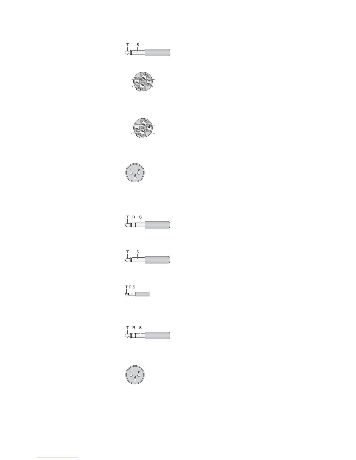
6 Specifications
Block diagram see page 49
Output power
rms power
at 4 Ω speaker: . . . . 2 × 475 W
at 8 Ω speaker: . . . . 2 × 260 W
bridged operation: . . 1 × 900 W at 8 Ω
Maximum power: . . . . 2 × 700 W at 4 Ω
Inputs
(sensitivity/ impedance; connection)
Mic: . . . . . . . . . . . . . . 1 mV/ 3 kΩ;
XLR, balanced
Line (mono channel): . 10 mV/ 27 kΩ;
6.3 mm jack, bal.
Line (stereo channel): 75 mV/ 10 kΩ;
6.3 mm jack, bal.
Tape In: . . . . . . . . . . . 100 mV/ 20 kΩ; RCA,
3.5 mm jack, unbal.
Aux Return: . . . . . . . . 80 mV/ 26 kΩ;
6.3 mm jack, bal.
Outputs
(level / impedance; connection)
Main Out, stereo: . . . . 1.5 V (at indication
0 dB) /120 Ω;
6.3 mm jack, bal.
Monitor Out, mono: . . 10 V/120 Ω;
6.3 mm jack, unbal.
Tape Out, stereo: . . . . 800 mV/1 kΩ; RCA
FX Send mono: . . . . . 10 V/120Ω;
6.3 mm jack, unbal.
Headphone impedance: ≥ 8 Ω
Frequency range: . . . . . 20 – 20 000 Hz
THD: . . . . . . . . . . . . . . . < 0.04 %
S/N ratio: . . . . . . . . . . . . 89 dB
Crosstalk: . . . . . . . . . . .
-
63 dB
Equalizer controls for CH 1 – 12
bass frequencies: . . . . ±15 dB at 80Hz
mid-frequencies: . . . . ±12 dB at 2.5kHz
high frequencies: . . . . ±15 dB at 12kHz
Equalizer for
Main Mix and Monitor: . . ±15 dB at
63 / 160 / 400 Hz /
1/ 2.5 / 6,3 /16 kHz
Compressor
threshold: . . . . . . . . . .
-
40 dB to +22 dB
ratio: . . . . . . . . . . . . . . 2 : 1 to ∞ : 1
attack time: . . . . . . . . 1 ms
release time: . . . . . . . 2 s
Phantom power
for Mic 1 – 9: . . . . . . . . . +48 V
Voltage for console light: 12 V/500 mA
Mains voltage: . . . . . . . . 230 V~ / 50 Hz
Power consumption
at no-load operation: . 65 VA
at maximum output
power: . . . . . . . . . . . . 1250 VA
Ambient temperature: . . 0 – 40 °C
Dimensions
(W × H × D): . . . . . . . . . 465 × 150 × 395 mm
Weight: . . . . . . . . . . . . . 10.1 kg
6.1 Plug configuration
Speaker connections
for stereo operation or 2-channel operation
2-pole 6.3 mm plug
SPEAKON
®
compatible plug
Speaker connection at jack “A”
for bridged operation
SPEAKON
®
compatible plug
Microphone connections
XLR plug for balanced connection
Line signal connections
3-pole 6.3 mm plug
for balanced connection
2-pole 6.3 mm plug
for unbalanced connection
3-pole 3.5 mm plug
for stereo signals (Tape In)
Headphone connection
6.3 mm stereo plug
Connection for a console light
XLR plug
Subject to technical modification.
1 = negative pole 12 V
2 = positive pole 12 V
3 = free
T = left channel
R = right channel
S = ground
T = left channel
R = right channel
S = ground
T = signal
S = ground
T = signal +
R = signal
-
S = ground
1 = ground
2 = signal +
3 = signal
-
1+ = positive pole
2+ = negative pole
1+2
-
1
-
2+
1+ = positive pole
1
-
= negative pole
1+2
-
1
-
2+
T = positive pole
S = negative pole
15
English
All rights reserved by MONACOR®INTERNATIONAL GmbH & Co. KG. No part of this instruction
manual may be reproduced in any form or by any means for any commercial use.
 Loading...