

IMG STAGE LINE PMX-500SET Instruction Manual
TRANSPORTABLES
STEREO-VERSTÄRKERSYSTEM
PORTABLE STEREO AMPLIFIER SYSTEM
SYSTÈME AMPLIFIÉ STÉRÉO PORTABLE
SISTEMA DI AMPLIFICAZIONE STEREO TRASPORTABILE
PMX-500SET Best.-Nr. 25.0390
BEDIENUNGSANLEITUNG • INSTRUCTION MANUAL • MODE D’EMPLOI
ISTRUZIONI PER L’USO • GEBRUIKSAANWIJZING • MANUAL DE INSTRUCCIONES • INSTRUKCJA OBSŁUGI
SIKKERHEDSOPLYSNINGER • SÄKERHETSFÖRESKRIFTER • TURVALLISUUDESTA

wwwwww..iimmggssttaaggeelliinnee..ccoomm
Bevor Sie einschalten …
Wir wünschen Ihnen viel Spaß mit Ihrem neuen Gerät
von „img Stage Line“. Bitte lesen Sie diese Bedienungsanleitung vor dem Betrieb gründlich durch. Nur so lernen
Sie alle Funktionsmöglichkeiten kennen, vermeiden
Fehlbedienungen und schützen sich und Ihr Gerät vor
eventuellen Schäden durch unsachgemäßen Gebrauch.
Heben Sie die Anleitung für ein späteres Nachlesen auf.
Der deutsche Text beginnt auf der Seite 4.
Before switching on …
We wish you much pleasure with your new “img Stage
Line” unit. Please read these operating instructions carefully prior to operating the unit. Thus, you will get to know
all functions of the unit, operating errors will be prevented, and yourself and the unit will be protected
against any damage caused by improper use. Please
keep the oper ating instructions for later use.
The English text starts on page 4.
Avant toute installation …
Nous vous souhaitons beaucoup de plaisir à utiliser cet
appareil “img Stage Line”. Lisez ce mode dʼemploi entièrement avant toute utilisation. Uniquement ainsi, vous
pourrez apprendre lʼensemble des possibilités de fonctionnement de lʼappareil, éviter toute manipulation erronée
et vous protéger, ainsi que lʼappareil, de dommages éventuels engendrés par une utilisation inadaptée. Conservez la notice pour pouvoir vous y reporter ultérieurement.
La version française se trouve page 7.
Prima di accendere …
Vi auguriamo buon divertimento con il vostro nuovo
apparecchio di “img Stage Line”. Leggete attentamente
le istruzioni prima di mettere in funzione lʼapparecchio.
Solo così potete conoscere tutte le funzionalità, evitare
comandi sbagliati e proteggere voi stessi e lʼapparecchio
da eventuali danni in seguito ad un uso improprio. Conservate le istruzioni per poterle consultare anche in
futuro.
Il testo italiano inizia a pagina 7.
D
A
CH
GB
Antes de la utilización …
Le deseamos una buena utilización para su nue vo aparato “img Stage Line”. Por favor, lea estas in s trucciones
de uso atentamente antes de ha cer funcionar el aparato.
De esta manera conocerá todas las funciones de la unidad, se pre vendrán errores de operación, usted y el apa rato estarán protegidos en contra de todo daño cau sado
por un uso inadecuado. Por favor, guarde las instrucciones para una futura utilización.
La versión española comienza en la página 10.
Voor u inschakelt …
Wij wensen u veel plezier met uw nieuwe apparaat van
“img Stage Line”. Lees deze gebruikershandleiding grondig door, alvorens het apparaat in gebruik te nemen.
Alleen zo leert u alle functies kennen, vermijdt u foutieve
bediening en behoedt u zichzelf en het apparaat voor
eventuele schade door ondeskundig gebruik. Bewaar de
handleiding voor latere raadpleging.
De Nederlandstalige tekst vindt u op pagina 10.
Przed uruchomieniem …
Życzymy zadowolenia z nowego produktu “img Stage
Line”. Dzięki tej instrukcji obsługi będą państwo w stanie
poznać wszystkie funkcje tego urządzenia. Stosując się
do instrukcji unikną państwo błędów i ewentualnego
uszkodzenia urządzenia na skutek nieprawidłowego
użytkowania. Prosimy zachować instrukcję.
Tekst polski zaczyna się na stronie 14.
Før du tænder …
Tillykke med dit nye “img Stage Line” produkt. Læs sikkerhedsanvisningerne nøje før ibrugtagning, for at
beskytte Dem og enheden mod skader, der skyldes forkert brug. Gem venligst denne betjeningsvejledning til
senere brug.
Sikkerhedsanvisningerne findes på side 16.
Innan du slår på enheten …
Vi önskar dig mycket glädje med din nya “img Stage
Line” produkt. Läs igenom säkerhetsföre skrifterna innan
en heten tas i bruk för att undvika skador till följd av
felaktig hantering. Behåll instruktionerna för framtida
bruk.
Säkerhetsföreskrifterna återfinns på sidan 16.
Ennen kytkemistä …
Toivomme Sinulle paljon miellyttäviä hetkiä uuden “img
Stage Line” laitteen kanssa. Ennen laitteen käyttöä pyydämme Sinua huolellisesti tutustumaan turvallisuusohjeisiin. Näin vältyt vahingoilta, joita virheellinen laitteen
käyttö saattaa aiheuttaa. Ole hyvä ja säilytä käyttöohjeet
myöhempää tarvetta varten.
Turvallisuusohjeet löytyvät sivulta 16.
F
B
CH
I
ENL
PL DK
S FIN
B
2
1
2
2
3
4
4
4
5
6
7
8
9
10
11
12
13
14
16
17
18
15
3
Bitte klappen Sie die Seite 3 heraus. Sie sehen
dann immer die beschriebenen Bedien elemente
und Anschlüsse.
1 Übersicht der Bedienelemente
und Anschlüsse
Powermixer, in die Rückseite einer Lautsprecherbox
eingebaut (Abb. 1)
1 Buchse der Lautsprecherbox zum Anschluss an
eine der SPEAKER-Buchsen (5) des Power mixers; passendes Kabel liegt bei
2 Netzbuchse zum Anschluss an eine Steckdose
(230 V~/50 Hz) über das beiliegende Netzkabel
3 Ein- und Ausschalter POWER
4 Verriegelungsschrauben, um den Powermixer im
Fach zu sichern
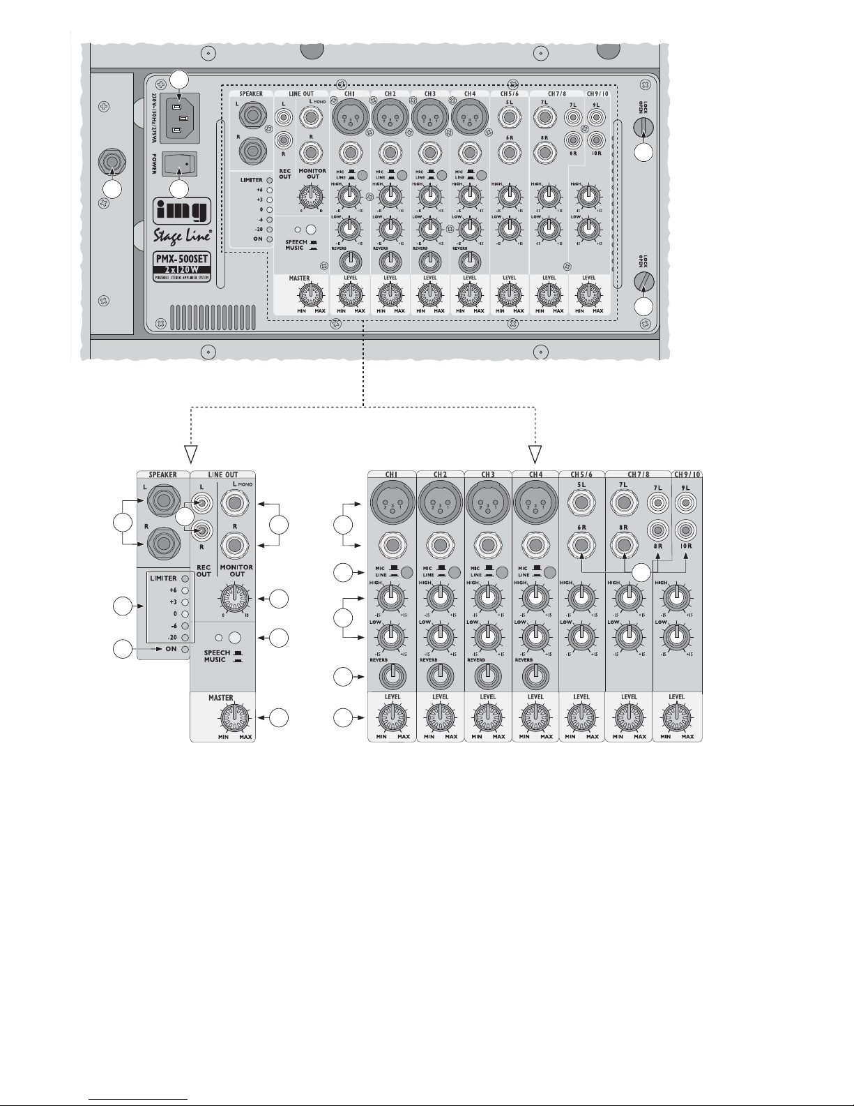
1.1 Ausgangsfeld (Abb. 2)
5 Stereo-Ausgang SPEAKER (6,3-mm-Klin ken -
buch sen) zum An schluss der beiden Lautsprecherboxen
6 Stereo-Ausgang REC OUT (Cinch-Buchsen)
zum Anschluss eines Aufnahmegeräts; der Aufnahmepegel wird nicht vom Regler MASTER
(12) beeinflusst
7 Stereo-Ausgang MONITOR OUT (6,3-mm-Klin -
ken buch sen, asym.): hier kann der Verstär ker
einer Monitoranlage angeschlossen werden
Hinweis: Bei Anschluss eines Mono-Geräts nur
die obere Buchse L
MONO verwenden.
8 LED-Pegelanzeige, zeigt den mit dem Regler
MASTER (12) eingestellten Pegel am Lautsprecherausgang (5); die rote LIMITER-LED sollte
höchstens bei Signalspitzen kurz aufleuchten
9 Betriebsanzeige ON:
leuchtet im Betrieb;
blinkt bei aktiver Schutzschaltung
10 Lautstärkeregler MONITOR OUT: bestimmt den
Pegel, mit dem das Mischsignal auf den Monitorausgang (7) gegeben wird
11 SPEECH/ MUSIC-Taste zum Ein-/Ausschalten
eines Low-Cut-Filters für das Mischsignal
Taste nicht gedrückt:
Filter aktiv (optimal für Sprachanwendungen)
Taste gedrückt, LED daneben leuchtet:
Filter nicht aktiv (optimal für Musikwiedergabe)
12 Lautstärkeregler MASTER: bestimmt den Pegel,
mit dem das Mischsignal auf den Lautsprecherausgang (5) gegeben wird
1.2 Eingangskänale (Abb. 3)
13 symmetrische Mono-Eingänge (XLR-Buchsen
und 6,3-mm-Klin ken buch sen) für die Ka näle 1
bis 4 zum Anschluss von Mikrofonen und MonoTonquellen mit Line-Ausgangspegel wie z. B.
Instrumentenverstärker, Effekt gerät
Hinweis: Pro Kanal
entweder
die XLR-
oder
die
Klinkenbuch se verwenden.
14 MIC/ LINE-Umschalter für die Ka näle 1 – 4; bei
gedrückter Taste wird der Pegel des Eingangssignals um 30 dB gedämpft
Taste nicht gedrückt:
erforderlich bei Anschluss eines Mikrofons
Taste gedrückt:
erforderlich bei Anschluss einer Tonquelle mit
Line-Ausgangspegel
15 asymmetrische Stereo-Eingänge (6,3-mm-Klin -
ken buch sen und Cinch-Buchsen) für die Ka näle
5/ 6, 7/ 8 und 9/ 10 zum Anschluss von StereoTonquellen mit Line-Ausgangspegel wie z. B.
Keyboard, CD-Spieler
Hinweis: Bei Kanal 7/ 8
entweder
die Klinken-
oder
die Cinch-Buch sen verwenden.
16 Klangregler für die Eingangskänale, pro Kanal ein
Höhenregler HIGH und ein Tiefenregler LOW
17 Effektregler REVERB, um für jeden Kanal 1 – 4
die Intensität des Halleffekts getrennt einzustellen
18 Lautstärkeregler LEVEL für die Eingangskanäle
2 Hinweise für den sicheren Gebrauch
Das Verstärkersystem entspricht allen erforderlichen Richtlinien der EU und ist deshalb mit
gekennzeichnet.
Beachten Sie auch unbedingt die folgenden Punkte:
G
Das Verstärkersystem ist nur zur Verwendung im
Innenbereich geeignet. Schützen Sie alle Komponenten vor Tropf- und Spritzwasser, hoher Luftfeuchtigkeit und Hitze (zulässiger Einsatztemperaturbereich 0 – 40 °C).
G
Stellen Sie keine mit Flüssigkeit gefüllten Gefäße,
z. B. Trinkgläser, auf die Geräte.
G
Die im Powermixer entstehende Wärme muss
durch Luftzirkulation abgegeben werden. Decken
Sie darum die Lüftungsöffnungen nicht ab.
G
Nehmen Sie den Powermixer nicht in Betrieb bzw.
ziehen Sie sofort den Netzstecker aus der Steckdose,
1. wenn sichtbare Schäden am Gerät oder an der
Netzanschlussleitung vorhanden sind,
2. wenn nach einem Sturz oder Ähnlichem der
Verdacht auf einen Defekt besteht,
3. wenn Funktionsstörungen auftreten.
Geben Sie das Gerät in jedem Fall zur Reparatur
in eine Fachwerkstatt.
WARNUNG Der Powermixer wird mit lebensge-
fähr licher Netzspannung versorgt.
Nehmen Sie deshalb niemals selbst
Eingriffe am Gerät vor und stecken
Sie nichts durch die Lüftungs öff nungen! Es besteht die Gefahr eines
elektrischen Schlages.
Please unfold page 3. Then you can always see
the operating elements and connections described.
1 Operating Elements and Connections
Power mixer, built into the rear side of a speaker system (fig. 1)
1 Jack of the speaker system for connection to one
of the SPEAKER jacks (5) of the power mixer;
matching cable is supplied
2 Mains jack for connection to a socket (230 V~/
50 Hz) via the supplied mains cable
3 POWER switch
4 Locking screws to secure the power mixer in the
compartment
1.1 Output field (fig. 2)
5 Stereo output SPEAKER (6.3 mm jacks) for con-
nection of both speaker systems
6 Stereo output REC OUT (phono jacks) for con-
nection of a recorder; the recording level is not
affected by the control MASTER (12)
7 Stereo output MONITOR OUT (6.3 mm jacks,
unbal.): here the amplifier of a monitor system
may be connected
Note: When connecting a mono unit, only use the
upper jack L
MONO.
8 LED level indication, shows the level at the
speaker output (5) adjusted with the control
MASTER (12); the red LIMITER LED should
shortly light up at signal peaks only
9 Power LED ON:
lights up during operation;
flashes with active protective circuit
10 Volume control MONITOR OUT: defines the
level by which the mixed signal is fed to the monitor output (7)
11 SPEECH/MUSIC button to switch a low cut filter
for the mixed signal on and off
Button not pressed:
Filter active (ideal for speech applications)
Button pressed, LED next to it lights up:
Filter not active (ideal for music reproduction)
12 Volume control MASTER: defines the level by
which the mixed signal is fed to the speaker output (5)
1.2 Input channels (fig. 3)
13 Balanced mono inputs (XLR jacks and 6.3 mm
jacks) for channels 1 to 4 for connection of microphones and mono audio sources with line output
level, e. g. amplifier of musical instruments, effect
unit
Note:
Either
use the XLR jack orthe 6.3 mm jack
for each channel
14 MIC/LINE selector switches for channels 1 to 4;
with the button pressed, the level of the input signal is attenuated by 30 dB
Button not pressed:
required when connecting a microphone
Button pressed:
required when connecting an audio source
with line output level
15 Unbalanced stereo inputs (6.3 mm jacks and
phono jacks) for channels 5/6, 7/8, and 9/10 for
connection of stereo audio sources with line output level, e. g. keyboard, CD player
Note:
Either
use the 6.3 mm jacks orthe phono
jacks for channel 7/8.
16 Equalizer controls for the input channels, control
HIGH for the high range and control LOW for the
low range for each channel
17
Effect controls REVERB to adjust the intensity of
the reverb effect separately for each channel 1 to 4
18 Volume controls LEVEL for the input channels
2 Safety Notes
The amplifier system corresponds to all required
directives of the EU and is therefore marked with .
It is essential to observe the following items:
G
The amplifier system is suitable for indoor use
only. Protect all components against dripping
water and splash water, high air humidity, and heat
(admissible ambient temperature range 0 – 40 °C).
G
Do not place any vessels filled with liquid, e. g.
drinking glasses, on the units.
G
The heat being generated inside the power mixer
must be carried off by air circulation. Therefore,
the air vents at the housing must not be covered.
G
Do not set the power mixer into operation, or
immediately disconnect the mains plug from the
mains socket if
1. there is visible damage to the unit or to the
mains cable,
2. a defect might have occurred after a drop or
similar accident,
3. malfunctions occur.
The unit must in any case be repaired by skilled
personnel.
G
Never pull the mains cable to disconnect the
mains plug from the mains socket, always seize
the plug.
WARNING The power mixer is supplied with haz-
ardous mains voltage. Leave servicing to skilled personnel only. Do not
insert anything through the air vents!
Inexpert handling or modification of
the unit may cause an electric shock
hazard.
D
A
CH
4
GB

G
Ziehen Sie den Netzstecker nie am Kabel aus der
Steckdose, fassen Sie immer am Stecker an.
G
Verwenden Sie für die Reinigung nur ein trockenes, weiches Tuch, nie Wasser oder Chemikalien.
G
Werden die Komponenten des Systems zweckentfremdet, nicht richtig montiert oder angeschlossen,
falsch be dient oder nicht fach gerecht repariert,
kann keine Haftung für daraus resultierende Sachoder Personenschäden und keine Garantie für die
Geräte übernommen werden.
3 Einsatzmöglichkeiten
Das Verstärkersystem PMX-500SET ist ideal für den
mobilen Einsatz geeignet, z. B. für Live-Auftritte kleiner Bands, Tanzveranstaltungen, Vorführungen etc.
Es besteht aus einem Powermixer (Kombination aus
Mischpult mit integriertem Digital-Halleffekt und
Stereo-Verstärker) und zwei Laut spre cher boxen.
Der Powermixer bietet 4 Mono- und 3 Ste reo-Kanäle
zum Anschluss von Mikrofonen und Line-Tonquellen
wie z. B. Instrumentenverstärker, CD-Spieler. Die
Endstufe liefert eine Leistung von 2 × 120 WMAX und
verfügt über eine Limiter-Schaltung und einen Kurzschluss- und Überhitzungsschutz. Zum Lieferumfang gehören außerdem ein Netzkabel, zwei 5-mLautsprecher kabel und eine Halterung zur Montage
des Powermixers auf ein Mikrofonstativ.
4 Aufstellung
Für den Transport des Systems ist jede Lautsprecherbox auf der Rückseite mit einem Fach ausgestattet: im Fach der einen Box wird der Powermixer
untergebracht, im Fach der anderen Box das Zube-
hör. Der Power mixer kann während des Betriebs in
der Box verbleiben oder herausgenommen werden.
Zum Herausnehmen erst die zwei Verriegelungsschrauben (4) entfernen, dann das Gerät an seinen
Tragegriffen aus dem Fach herausheben. An der
zweiten Box die beiden Verriegelungsschrauben des
Fachdeckels entfernen, das Fach öffnen und das
Zubehör (Anschlusskabel und Stativhalterung für
den Powermixer) herausnehmen. Über die Halterung lässt sich der Powermixer auf ein Mikrofonstativ mit 15,9-mm-Gewinde (
5
⁄8") montieren; sie wird
an den zwei Gewindebuchsen auf der Rückseite des
Powermixers befestigt.
Die Lautsprecherboxen können frei auf dem
Boden aufgestellt werden: entweder hochkant oder
auf die abgeschrägte Seite, so dass der Schall nach
schräg oben ab strahlt. Über die Stativhülse an der
Unterseite lässt sich jede Box auch auf ein PABoxenstativ montieren.
5 Anschluss
Vor dem Anschließen von Geräten oder vor dem
Ändern bestehender Anschlüsse den Powermixer
ausschalten.
5.1 Tonquellen
An die Eingänge (13) der Mono-Kanäle 1 bis 4 können Mikrofone und Mono-Geräte mit Line-Aus-
gangspegel (z. B. Instrumentenverstärker, Effektgerät) angeschlossen werden. Pro Kanal
entweder
die XLR-
oder
die 6,3-mm-Klinkenbuchse verwenden, nicht beide gleichzeitig. Die Eingänge der
Mono-Kanäle sind für symmetrische Signale ausgelegt. Es können jedoch auch Tonquellen mit asymmetrischen Ausgangssignalen angeschlossen werden: diese entweder über 2-po lige Klinkenstecker
an schließen oder über XLR-Adapter, bei denen die
Pins 1 und 3 gebrückt sind.
Stereo-Geräte mit Line-Ausgangpegel (z. B. Keyboard, CD-Spieler) können an die asymmetrisch
beschalteten Eingänge (15) der Stereo-Kanäle 5/ 6
bis 9/ 10 angeschlossen werden: L = linker Kanal,
R = rechter Kanal.
Kanal 5/ 6: Anschluss über 6,3-mm-Klinken buch -
sen
Kanal 7/ 8: Anschluss
entweder
über 6,3-mm-
Klin ken buch sen
oder
über CinchBuchsen; nicht beide Buchsenpaare
gleichzeitig verwenden
Kanal 9/ 10: Anschluss über Cinch-Buchsen
5.2 Lautsprecherboxen
Die Anschlussbuchsen (1) der beiden Lautsprecherboxen über die zwei mitgelieferten Laut spre cher kabel mit jeweils einer Buchse SPEAKER (5) des
Powermixers verbinden: L = linker Kanal, R = rechter Kanal.
5.3 Aufnahmegerät
Ein Aufnahmegerät kann an die Cinch-Buchsen
REC OUT (6) angeschlossen werden: L = linker Ka nal, R = rechter Kanal. Am Ausgang REC OUT steht
das Mischsignal der Eingangskanäle zur Verfügung,
unbeeinflusst vom Regler MASTER (12).
5.4 Verstärker einer Monitoranlage
Wird eine Monitoranlage zum Abhören des Mischsignals eingesetzt, kann der Verstärker der Monitoranlage an die 6,3-mm-Klinkenbuchsen MONITOR
OUT (7) angeschlossen werden: L = linker Kanal,
R = rechter Kanal; bei einem Mono-Gerät nur die
obere Buchse L MONO verwenden.
5.5 Stromversorgung
Das beiliegende Netzkabel an die Netzbuchse (2)
anschließen und den Netzstecker in eine Steckdose
(230 V~/50 Hz) stecken.
Soll das System endgültig aus dem Betrieb
genommen werden, übergeben Sie es zur
umweltgerechten Entsorgung einem örtlichen Recyclingbetrieb.
G
For cleaning only use a dry, soft cloth, never use
chemicals or water.
G
No guarantee claims for the units and no liability
for any resulting personal damage or material
damage will be accepted if the components of the
system are used for other purposes than originally
intended, if they are not correctly mounted or connected or operated, if they are not repaired in an
expert way.
G
Important for U. K. Customers!
The wires in this mains lead are coloured in accordance with the following code:
green/yellow = earth
blue = neutral
brown = live
As the colours of the wires in the mains lead of this
appliance may not correspond with the coloured
markings identifying the terminals in your plug,
proceed as follows:
1. The wire which is coloured green and yellow
must be connected to the terminal in the plug
which is marked with the letter E or by the earth
symbol , or coloured green or green and yellow.
2. The wire which is coloured blue must be connected to the terminal which is marked with the
letter N or coloured black.
3. The wire which is coloured brown must be connected to the terminal which is marked with the
letter L or coloured red.
Warning – This appliance must be earthed.
3 Applications
The amplifier system PMX-500SET is ideal for
mobile applications, e. g. for live performances of
smaller bands, dance events, presentations, etc. It
consists of a power mixer (combination of mixer with
integrated digital reverb effect and stereo amplifier)
and two speaker systems. The power mixer offers
4 mono and 3 stereo channels for connection of
microphones and line audio sources, e. g. amplifier
for musical instruments, CD player. The power
amplifier supplies a power of 2 × 120 W
MAX and has
a limiter circuit and protection against short circuit
and overheating. The unit is supplied with a mains
cable, two 5 m speaker cables, and a support for
mounting the power mixer onto a microphone stand.
4 Setting-up
For transporting the system each speaker cabinet is
equipped with a compartment on the rear side: The
power mixer is accommodated in the compartment
of one cabinet, the accessories in the compartment
of the other cabinet. While operating, the power
mixer can remain in the cabinet or be taken out of it.
For taking out, first remove the two locking screws
(4), then lift the unit at its carrying handles out of the
compartment. Remove the two locking screws of the
compartment cover of the second cabinet, open the
compartment, and take out the accessories (connecting cables and stand support for the power
mixer). The power mixer can be mounted onto a
microphone stand with 15.9 mm ( 5⁄8") thread via its
support; it is fixed at the two threaded jacks on the
rear side of the power mixer.
The speaker systems may be placed on the
ground as desired: either edgewise or on the bevelled wall so that the sound will be radiated diagonally upwards. Each cabinet can also be mounted
onto a PA speaker stand via the stand sleeve at the
lower side.
5 Connection
Prior to connecting units or changing existing connections switch off the power mixer.
5.1 Audio sources
Microphones or mono units with line output level
(e. g. amplifier for musical instruments, effect unit)
may be connected to the inputs (13) of the mono
channels 1 to 4.
Either
use the XLR jack orthe
6.3 mm jack for each channel, not both jacks at the
same time. The inputs of the mono channels are
designed for balanced signals. However, also audio
sources with unbalanced output signals may be connected: either connect them via 2-pole 6.3 mm plugs
or via XLR adapters at which pins 1 and 3 are
bridged.
Stereo units with line output level (e. g. keyboard,
CD player) may be connected to the unbalanced
inputs (15) of the stereo channels 5/ 6 to 9/ 10:
L = left channel, R = right channel.
Channel 5/ 6: Connection via 6.3 mm jacks
Channel 7/ 8: Connection
either
via 6.3 mm jacks
or
via phono jacks: do not use both
pairs of jacks at the same time
Channel 9/ 10: Connection via phono jacks
5.2 Speaker systems
Connect in each case the jacks (1) of both speaker
systems via the two supplied speaker cables to one
jack SPEAKER (5) of the power mixer: L = left channel, R = right channel.
5.3 Recorder
A recorder may be connected to the phono jacks
REC OUT (6): L = left channel, R = right channel. At
the output REC OUT the mixed signal of the input
channels is available, not affected by the control
MASTER (12).
5.4 Amplifier of a monitor system
If a monitor system is used for monitoring the mixed
signal, the amplifier of the monitor system may be
connected to the 6.3 mm jacks MONITOR OUT (7):
L = left channel, R = right channel; only use the
upper jack L MONO for a mono unit.
If the system is to be put out of operation
definitively, take it to a local recycling plant
for a disposal which is not harmful to the
environment.
D
A
CH
5
GB

6 Inbetriebnahme
1) Um Einschaltgeräusche und eine zu hohe Lautstär ke zu vermeiden, vor dem Einschalten die
Ausgangsregler (10 und 12) ganz nach links
zurückdrehen.
2) Für die Kanäle 1 – 4 die MIC/ LINE-Tasten (14) je
nach an geschlossener Tonquelle betätigen: Bei
Mikrofonanschluss die Taste ausrasten, bei An schluss eines Geräts mit Line-Signalpegel die
Taste drücken (Pegel des Eingangssignals wird
um 30 dB abgesenkt).
3) Erst die Tonquellen einschalten, dann den
Powermixer mit dem Ein-/Ausschalter POWER
(3). Sind am Powermixer zusätzliche Endverstärker zur Be schallung angeschlossen, diese zuletzt
einschalten.
Bei eingeschaltetem Powermixer leuchtet die
Betriebsanzeige ON (9). Blinkt sie, hat die Schutzschaltung angesprochen, z. B. bei Kurzschluss an
den Lautsprecheranschlüssen. In diesem Fall den
Powermixer ausschalten, die Fehlerursache be seitigen und das Gerät wieder in Betrieb nehmen.
4) Nach dem Betrieb die Geräte in umgekehrter Reihenfolge ausschalten.
7 Bedienung
Die folgenden Bedienschritte dienen nur als Hilfestel lung, es sind auch andere Vorgehensweisen
möglich.
1) Zur Grundeinstellung alle Klangregler HIGH und
LOW (16) in Mittelstellung drehen, alle Effektregler REVERB (17) und Lautstärkeregler LEVEL
(18) ganz nach links zurückdrehen und den Regler MASTER (12) für die Gesamtlautstär ke etwa
zur Hälfte aufziehen, so dass alle weiteren Einstellungen über die Lautsprecher zu hören sind.
2) Die Tonsignale auf die Eingangskanäle geben
und mit den Reglern LEVEL (18) das gewünschte
Lautstärkeverhältnis der Tonquellen einstellen.
Die Regler LEVEL nicht benutzter Kanäle immer
ganz zurückdrehen.
3) Für jeden Eingangskanal getrennt den Klang mit
den Klangreglern (16) einstellen: HIGH für die
Höhen, LOW für die Tiefen.
4) Mit den Reglern REVERB (17) für jeden der
Kanäle 1 – 4 die gewünschte Effektintensität einstellen: je weiter ein Regler aufgedreht wird,
desto stärker wird der Halleffekt für den Kanal.
Soll kein Effekt zugemischt werden, den jeweiligen Regler ganz zurückdrehen.
5) Mit der Taste SPEECH/ MUSIC (11) lässt sich für
das Mischsignal ein Low-Cut-Filter (Hochpass filter) aktivieren/ de aktivieren: Bei nicht gedrückter Taste durchläuft das Signal das Filter, d. h. zur
besseren Sprachverständlichkeit werden sehr
tiefe Frequen zen wie z. B. Trittschall unterdrückt.
Bei ge drückter Taste (LED daneben leuchtet) ist
das Filter deaktiviert.
6) Mit dem Regler MASTER (12) den endgültigen
Pegel einstellen, mit dem das Mischsignal auf die
Lautsprecher gegeben wird; die Pe gelanzeige (8)
zeigt den Pegel des MASTER-Signals an. Die
rote LIMITER-LED leuchtet, wenn die interne
Endstufe durch einen zu hohen Pegel übersteuert wird, so dass die Limiter-Schal tung (Begrenzung des Pe gels) an spricht. Die LIMITER-LED
sollte höchs tens bei Signalspitzen kurz aufleuchten. Leuchtet sie permanent, den Regler MASTER entsprechend zu rückdrehen.
7) Mit dem Regler MONITOR OUT (10) den Pegel
einstellen, mit dem das Mischsignal auf den
Monitorausgang (7) gegeben wird.
8 Technische Daten
Ausgangsleistung an 8 Ω: . . 2 × 75 WRMS
2 × 120 WMAX
Frequenzbereich: . . . . . . . . 50 – 22 000Hz
Eingangsempfindlichkeit
Mikrofonanschluss: . . . . . 2 mV
Line-Anschluss: . . . . . . . 120 mV
Aufnahmeausgang: . . . . . . 250 mV
Monitorausgang: . . . . . . . . . 1,2 V
Klangregler
Tiefen: . . . . . . . . . . . . . . ±15 dB / 100 Hz
Höhen: . . . . . . . . . . . . . . ±15 dB / 10 kHz
Stromversorgung: . . . . . . . . 230 V~ / 50 Hz
Leistungsaufnahme: . . . . . . 275 VA
Einsatztemperatur: . . . . . . . 0 –40 °C
Abmessungen
Powermixer: . . . . . . . . . . 301 × 86 × 55 mm
Lautsprecherbox: . . . . . . 340 × 535 × 280 mm
Gesamtgewicht: . . . . . . . . . 22,6 kg
Änderungen vorbehalten.
VORSICHT Stellen Sie die Lautstärke der Audio-
anlage nie sehr hoch ein. Hohe Lautstärken können auf Dauer das Gehör
schädigen! Das Ohr gewöhnt sich an
hohe Lautstärken und empfindet sie
nach einiger Zeit als nicht mehr so
hoch. Erhöhen Sie darum eine hohe
Laut stär ke nach der Gewöhnung
nicht weiter.
5.5 Power supply
Connect the supplied mains cable to the mains jack
(2) and the mains plug to a socket (230 V~/50 Hz).
6 Setting into Operation
1) To prevent switching noise and a volume which is
too high, turn the output controls (10 and 12) to
the left stop prior to switching-on.
2) For channels 1 to 4, actuate the MIC/LINE buttons (14) depending on the connected audio
source: Unlock the button if a microphone is connected, press the button if a unit with line signal
level is connected (level of the input signal is
attenuated by 30 dB).
3) First switch on the audio sources, then the power
mixer with the POWER switch (3). If additional
power amplifiers for PA applications are connected to the power mixer, switch them on last.
With the power mixer switched on, the power
LED ON (9) lights up. If it flashes, the protective
circuit has responded, e. g. in case of short circuit
at the speaker connections. In this case switch off
the power mixer, eliminate the reason for the
error, and reset the unit into operation.
4) After operation switch off the units in reverse
order.
7 Operation
The following operating steps only serve as an aid,
other ways of proceeding are possible.
1) For a basic setting, turn all equalizer controls
HIGH and LOW (16) to mid-position, turn back all
effect controls REVERB (17) and volume controls
LEVEL (18) to the left stop, and advance the control MASTER (12) for the overall volume approx.
half-way so that all further adjustments can be
heard via the speakers.
2)
Feed the audio signals to the input channels and
adjust the desired volume ratio of the audio sources
with the controls LEVEL (18). Always fully turn back
the controls LEVEL of the channels not used.
3) For each input channel separately adjust the
sound with the equalizers (16): HIGH for the high
range, LOW for the low range.
4) With the controls REVERB (17) adjust the
desired effect intensity for each of the channels 1
to 4: the further the control is advanced, the more
powerful is the reverb effect for the channel. For
not adding any effect, fully turn back the corresponding control.
5) With the button SPEECH/ MUSIC (11) a low cut
filter (high pass filter) may be activated/ deactivated for the mixed signal: With the button not
pressed, the signal passes through the filter, i. e.
very low frequencies, e. g. subsonic noise, are
suppressed for better speech intelligibility. With
the button pressed (LED next to it lights up) the filter is deactivated.
6) With the control MASTER (12) adjust the definite
level by which the mixed signal is fed to the
speakers; the level indication (8) shows the level
of the MASTER signal. The red LIMITER LED
lights up when the internal power amplifier is
overloaded by a level which is too high so that the
limiter circuit (limitation of the level) responds.
The LIMITER LED should shortly light up at signal peaks only. If it lights permanently, turn back
the control MASTER accordingly.
7) With the control MONITOR OUT (10) adjust the
level by which the mixed signal is fed to the monitor output (7).
8 Specifications
Output power at 8 Ω: . . . . . 2 × 75 WRMS
2 × 120 WMAX
Frequency range: . . . . . . . . 50 – 22 000 Hz
Input sensitivity
Microphone connection: . 2 mV
Line connection: . . . . . . . 120 mV
Recording output: . . . . . . . . 250 mV
Monitor output: . . . . . . . . . . 1.2 V
Equalizer
Low range: . . . . . . . . . . . ±15 dB/ 100 Hz
High range: . . . . . . . . . . . ±15 dB/ 10 kHz
Power supply: . . . . . . . . . . . 230 V~/ 50 Hz
Power consumption: . . . . . . 275 VA
Ambient temperature: . . . . . 0 – 40 °C
Dimensions
Power mixer: . . . . . . . . . 301 × 86 × 55 mm
Speaker system: . . . . . . . 340 × 535 × 280 mm
Total weight: . . . . . . . . . . . . 22.6 kg
Subject to technical modification.
CAUTION Never adjust the audio system to a
very high volume. Permanent high
volumes may damage your hearing!
The human ear will get accustomed to
high volumes which do not seem to be
that high any more after some time.
Therefore, do not further increase a
high volume after getting used to it.
D
A
CH
6
GB
Diese Bedienungsanleitung ist urheberrechtlich für MONACOR®INTERNATIONAL GmbH & Co. KG
geschützt. Eine Reproduktion für eigene kommerzielle Zwecke – auch auszugsweise – ist untersagt.
All rights reserved by MONACOR
®
INTERNATIONAL GmbH & Co. KG. No part of this instruction manual
may be reproduced in any form or by any means for any commercial use.
 Loading...