

IMG STAGE LINE PMX-400DSP, 20.1640 Instruction Manual
LO
+15–15 dB
0
HI
+15–15 dB
0
LO
+15–15 dB
0
HI
+15–15 dB
0
LO
+15–15 dB
0
HI
+15–15 dB
0
LO
+15–15 dB
0
HI
+15–15 dB
0
GAIN
LO
HI
GAIN
LO
HI
GAIN
LO
HI
GAIN
LO
HI
LEFT
(MONO)
RIGHT
5-6
LEFT
(MONO)
RIGHT
LEFT
(MONO)
RIGHT
LEFT
(MONO)
RIGHT
7-8 9-10 11-12
100
PHONES
5
THERMAL
PLAY
L
L
R
R
TAPE
TAPE
48V
PHANTOM
POWER
100
5
POWER
ON
L CLIP
R CLIP
LEVEL
REC
LOUDNESS
AMPLIFIER STATUS
600W
ON
OFF
+10 +50
+15
350 6k
RL
100
GAIN
HI
MID
LO
DSP
FX
MON
PAN
INST VOC
PEAK
PFL
MIC
LINE
1
1
C
5
0
Hz
–15 dB
+15–15 dB
0
+15–15 dB
0
100
5
+10 +50
+15
350 6k
RL
100
GAIN
HI
MID
LO
DSP
FX
MON
PAN
INST VOC
PEAK
PFL
MIC
LINE
2
2
C
5
0
Hz
–15 dB
+15–15 dB
0
+15–15 dB
0
100
5
+10 +50
+15
350 6k
RL
100
GAIN
HI
MID
LO
DSP
FX
MON
PAN
INST VOC
PEAK
PFL
MIC
LINE
3
3
C
5
0
Hz
–15 dB
+15–15 dB
0
+15–15 dB
0
100
5
+10 +50
+15
350 6k
RL
100
GAIN
HI
MID
LO
DSP
FX
MON
PAN
INST VOC
PEAK
PFL
MIC
LINE
4
4
C
5
0
Hz
–15 dB
+15–15 dB
0
+15–15 dB
0
100
5
RL
100
DSP
FX
MON
BAL
PEAK
PFL
5-6
C
5
100
5
RL
100
DSP
FX
MON
BAL
PEAK
PFL
7-8
C
5
100
5
RL
100
DSP
FX
MON
BAL
PEAK
PFL
9-10
C
5
100
5
RL
100
DSP
FX
MON
BAL
PEAK
PFL
11-12
C
5
100
5
PMX-400DSP
600W POWERED MIXER
LEFT
(MONO)
RIGHT
5-6
LEFT
(MONO)
RIGHT
LEFT
(MONO)
RIGHT
LEFT
(MONO)
RIGHT
7-8 9-10 11-12
MIC
LINE
1
MIC
LINE
2
MIC
LINE
3
MIC
LINE
4
OFF
ON
1234
DSP
PEAK
DSP
DELAY
REVERSE
GATED
PLATE 2
PLATE 1
XL REV
L REV
M REV
L REV
1
2
3
4
5
6
7
8
TIME
LONG SHORT
DSP
ON
USER
PRESETS
MULTITAB
3 TAB
2 TAB
CROSS
ECHO
AMBIENT
REGEN
VOCAL
5
LLR
R
FX
MON
LEFT
(MONO)
RIGHT
AUX
INPUT
OUTPUT
100 100
5
AUXINFX
OUT
RIGHTLEFT
+18
+15
+12
+9
+6
+3
0dBu
-3
-6
-9
-12
-18
LLR
R
MAIN OUT
MAIN/PFL
INSERT
(TIP: SEND RING: RETURN)
100
5
MON
OUT
100
5
DSP TO
MON
∞
-30
-20
-10
-5
+5
∞
-30
-20
-10
-5
0dB
+5
∞
-30
-20
-10
-5
0dB
+5
STEREO POWER MIXER
TABLE DE MIXAGE AMPLIFIÉE STÉRÉO
MIXER STEREO DI POTENZA
PMX-400DSP Best.-Nr. 20.1640
BEDIENUNGSANLEITUNG • INSTRUCTION MANUAL • MODE D’EMPLOI
ISTRUZIONI PER L’USO • GEBRUIKSAANWIJZING • HANDLEIDING
CONSEJOS DE SEGURIDAD • SIKKERHEDSOPLYSNINGER • SÄKERHETSFÖRESKRIFTER • TURVALLISUUDESTA

2
Bevor Sie einschalten ...
Wir wünschen Ihnen viel Spaß mit Ihrem neuen Gerät von
„img Stage Line“. Dabei soll Ihnen diese Bedienungsanleitung helfen, alle Funktionsmöglichkeiten kennen zu lernen. Die Beachtung der Anleitung vermeidet außerdem
Fehlbedienungen und schützt Sie und Ihr Gerät vor eventuellen Schäden durch unsachgemäßen Gebrauch.
Den deutschen Text finden Sie auf den Seiten 4–13.
Before you switch on ...
We wish you much pleasure with your new “img Stage
Line” unit. With these operating instructions you will be
able to get to know all functions of the unit. By following
these instructions false operations will be avoided, and
possible damage to yourself and your unit due to improper use will be prevented.
You will find the English text on the pages 4–13.
D
A
CH
GB
Voordat u inschakelt ...
Wij wensen u veel plezier met uw nieuw toestel van “img
Stage Line”. Met behulp van bijgaande gebruiksaanwijzing kunt u alle functiemogelijkheden leren kennen.
Door deze instructies op te volgen zal een slechte werking vermeden worden, en zal een eventueel letsel aan
uzelf en schade aan uw toestel tengevolge van onzorgvuldig gebruik worden voorkomen.
U vindt de nederlandstalige tekst op de pagina’s 24–28.
Antes de cualquier instalación
Tenemos de agradecerle el haber adquirido un aparato
“img Stage Line” y le deseamos un agradable uso. Por
favor lee las instrucciones de seguridad antes del uso.
La observación de las instrucciones de seguridad evita
operaciones erróneas y protege Vd. y vuestro aparato
contra todo daño posible por cualquier uso inadecuado.
Las instrucciones de seguridad se encuentran en la
página 29.
NL
B
E
Inden De tænder for apparatet ...
Vi ønsker Dem god fornøjelse med Deres nye “img
Stage Line” apparat. Læs oplysningerne for en sikker
brug af apparatet før ibrugtagning. Følg sikkerhedsoplysningerne for at undgå forkert betjening og for at beskytte Dem og Deres apparat mod skade på grund af forkert brug.
Sikkerhedsoplysningerne finder De på side 29.
Förskrift
Vi önskar dig mycket nöje med din nya “img Stage Line”
enheten. Läs gärna säkerhetsinstruktionerna innan du
använder enheten. Genom att följa säkerhetsinstruktionerna kan många problem undvikas, vilket annars kan
skada enheten.
Du finner säkerhetsinstruktionerna på sidan 29.
DK S
Ennen virran kytkemistä ...
T oivomme, että uusi “img Stage Line”-laitteesi tuo sinulle
paljon iloa ja hyötyä. Ole hyvä ja lue käyttöohjeet ennen
laitteen käyttöönottoa. Luettuasi käyttöohjeet voit käyttää laitetta turvallisesti ja vältyt laitteen väärinkäytöltä.
Käyttöohjeet löydät sivulta 29.
FIN
Avant toute mise en service ...
Nous vous remercions d’avoir choisi un appareil “img
Stage Line” et vous souhaitons beaucoup de plaisir à
l’utiliser. Cette notice a pour objectif de vous aider à
mieux connaître les multiples facettes de l’appareil. En
outre, en respectant les conseils donnés, vous éviterez
toute mauvaise manipulation de sorte que vous-même et
votre appareil soient protégés de tout dommage.
La version française se trouve pages 14–23.
Prima di accendere ...
Vi auguriamo buon divertimento con il Vostro nuovo
apparecchio “img Stage Line”. Le istruzioni per l’uso Vi
possono aiutare a conoscere tutte le possibili funzioni. E
rispettando quanto spiegato nelle istruzioni, evitate di
commettere degli errori, e così proteggete Voi stessi, ma
anche l’apparecchio, da eventuali rischi per uso improprio.
Il testo italiano lo potete trovare alle pagine 14–23.
F
B
CH
I
wwwwww..iimmggssttaaggeelliinnee..ccoomm
3
230V~/50Hz
POWER
LEFTRIGHT
SPEAKER OUTPUT (MIN. 4Ω)
SPEAKER
CONNECTIONS
1+1–2+
2–
+
–
WARNING:
AIR VENTS ON FRONT AND REAR MUST NOT BE OBSTRUCTED
PMX-400DSP
600W POWERED MIXER
MIC INPUTS
12
3
GND+
–
LINE INPUTS / OUTPUTS
SIGNALGND
UNBALANCED
+GND
BALANCED
–
DSP FOOTSWITCH
PEAK
PFL
MIC
LINE
1
1
PE
A
MIC
LINE
2
∞
–30
–20
–10
–5
0dB
+5
+10
+10 +50
+15
350 6k
RL
100
GAIN
HI
MID
LO
MON
PAN
INST VOC
C
5
0
Hz
–15 dB
+15–15 dB
0
+15–15 dB
0
100
5
+10
350
L
0
GAIN
HI
MID
LO
MON
PAN
INST
–15
–15
–15
0
DSP
FX
DSP
FX
600W
1
3
4
7
8
12
6
16
PEAK
PFL
MIC
LINE
1
1
PEAK
PFL
MIC
LINE
2
2
PEAK
PFL
MIC
LINE
3
3
PEAK
PFL
MIC
LINE
4
4
RL
100
MON
BAL
PEAK
PFL
5-6
C
5
100
5
RL
100
MON
BAL
PEAK
PFL
7-8
C
5
100
5
RL
100
MON
BAL
PEAK
PFL
9-10
C
5
100
5
RL
10
MON
BAL
PEAK
PFL
11-12
C
100
5
LO
+15–15 dB
0
HI
+15–15 dB
0
LO
+15–15 dB
0
HI
+15–15 dB
0
LO
+15–15 dB
0
HI
+15–15 dB
0
LO
+15–15 dB
0
HI
+15–15 dB
0
GAIN
LO
HI
GAIN
LO
HI
GAIN
LO
HI
GAIN
LO
HI
LEFT
(MONO)
RIGHT
5-6
LEFT
(MONO)
RIGHT
LEFT
(MONO)
RIGHT
LEFT
(MONO)
RIGHT
7-8 9-10 11-12
100
LEVEL
LOUDNESS
AMPLIFIER STATUS
OFF
ON
∞
–30
–20
–10
–5
0dB
+5
+10
∞
–30
–20
–10
–5
0dB
+5
+10
∞
–30
–20
–10
–5
0dB
+5
+10
∞
–30
–20
–10
–5
0dB
+5
+10
∞
–30
–20
–10
–5
0dB
+5
+10
∞
–30
–20
–10
–5
0dB
+5
+10
∞
–30
–20
–10
–5
0dB
+5
+10
∞
–30
–20
–10
–5
0dB
+5
+10
+10 +50
+15
350 6k
RL
100
GAIN
HI
MID
LO
MON
PAN
INST VOC
C
5
0
Hz
–15 dB
+15–15 dB
0
+15–15 dB
0
100
5
+10 +50
+15
350 6k
RL
100
GAIN
HI
MID
LO
MON
PAN
INST VOC
C
5
0
Hz
–15 dB
+15–15 dB
0
+15–15 dB
0
100
5
+10 +50
+15
350 6k
RL
100
GAIN
HI
MID
LO
MON
PAN
INST VOC
C
5
0
Hz
–15 dB
+15–15 dB
0
+15–15 dB
0
100
5
+10 +50
+15
350 6k
RL
100
GAIN
HI
MID
LO
MON
PAN
INST VOC
C
5
0
Hz
–15 dB
+15–15 dB
0
+15–15 dB
0
100
5
DSP
FX
DSPFXDSPFXDSPFXDSP
FX
DSPFXDSP
FX
DSP
FX
PMX-400DSP
600W POWERED MIXER
5
100 100
100
5
5
AUXINFX
OUT
MON
OUT
100
5
DSP TO
MON
∞
-30
-20
-10
-5
0
+5
∞
-30
-20
-10
-5
0
+5
LLR
R
INSERT
(TIP: SEND RING: RETURN)
FX
MON
LEFT
(MONO)
RIGHT
AUX
INPUT
OUTPUT
MAIN OUT
600W
RIGHTLEFT
+18
+15
+12
+9
+6
+3
0dBu
-3
-6
-9
-12
-18
MAIN/PFL
PHONES
5
ON
OFF
48V PHANTOM POWER
PLAY
L
LRR
TAPE
TAPE
REC
POWER ON
THERMAL
100
5
L CLIP
R CLIP
DIGITAL SIGNAL PROCESSOR
∞
-30
-20
-10
-5
0dB
+5
1234
DSP
PEAK
DSP
DELAY
REVERSE
GATED
PLATE 2
PLATE 1
XL REV
L REV
M REV
S REV
1
2
3
4
5
6
7
8
TIME
LONG SHORT
DSP
ON
USER
PRESETS
MULTITAB
3 TAB
2 TAB
CROSS
ECHO
AMBIENT
REGEN
VOCAL
17
18
20
19
A B C
➀
➁
49 50
4
RL
100
MON
BAL
PEAK
PFL
5-6
C
5
100
5
L
0
MON
BAL
PEA
7
0
LO
+15–15 dB
0
HI
+15–15 dB
0
LO
–15
HI
–15
GAIN
LO
HI
GAIN
LEFT
(MONO)
RIGHT
5-6 7-
∞
–30
–20
–10
–5
0dB
+5
+10
∞
–30
–20
–10
–5
0dB
+5
+10
0
VOC
0
DSP
FX
DSP
FX
600W
2
5
13
R
IGHT
∞
–30
–20
–10
–5
0dB
+5
+10
600W
DIGITAL SIGNAL PROCESSOR
∞
-30
-20
-10
-5
0dB
+5
1234
DSP
PEAK
DSP
DELAY
REVERSE
GATED
PLATE 2
PLATE 1
XL REV
L REV
M REV
S REV
1
2
3
4
5
6
7
8
TIME
LONG SHORT
DSP
ON
USER
PRESETS
MULTITAB
3 TAB
2 TAB
CROSS
ECHO
AMBIENT
REGEN
VOCAL
100
LEVEL
LOUDNESS
AMPLIFIER STATUS
OFF
ON
PMX-400DSP
600W POWERED MIXER
5
100 100
100
5
5
AUX
IN
FX
OUT
MON
OUT
100
5
DSP TO
MON
∞
-30
-20
-10
-5
0
+5
∞
-30
-20
-10
-5
0
+5
600W
RIGHTLEFT
+18
+15
+12
+9
+6
+3
0dBu
-3
-6
-9
-12
-18
MAIN/PFL
ON
OFF
48V PHANTOM POWER
PLAY
L
L
R
R
TAPE
TAPE
REC
POWER ON
THERMAL
100
5
L CLIP
R CLIP
LLR
R
INSERT
(TIP: SEND RING: RETURN)
FX
MON
LEFT
(MONO)
RIGHT
AUX
INPUT
OUTPUT
MAIN OUT
PHONES
5
36
25
26
35
27
28
29
30
31
32
33
34
45
37
38
39
42
43
44
40
41
11
9
10
14
15
21
22
23
24
46
47
48

Bitte klappen Sie die Seite 3 heraus. Sie sehen
dann immer die beschriebenen Bedienelemente
und Anschlüsse.
Inhalt
1 Einsatzmöglichkeiten . . . . . . . . . . . . . . . . 4
2 Übersicht der Bedienelemente und
Anschlüsse . . . . . . . . . . . . . . . . . . . . . . . . 4
2.1 Frontplatte . . . . . . . . . . . . . . . . . . . . . . . . . . 4
2.2 Rückseite . . . . . . . . . . . . . . . . . . . . . . . . . . 6
3 Hinweise für den sicheren Gebrauch . . . 6
4 Aufstellung/Rack-Montage . . . . . . . . . . . 7
5 Anschlüsse . . . . . . . . . . . . . . . . . . . . . . . . 7
5.1 Eingangskanäle . . . . . . . . . . . . . . . . . . . . . . 7
5.2 Effektgerät einschleifen . . . . . . . . . . . . . . . .7
5.2.1 Effektweg „FX” . . . . . . . . . . . . . . . . . . . . . 7
5.2.2 Insert-Buchsen . . . . . . . . . . . . . . . . . . . . . 7
5.3 Kopfhörer und Monitoranlage anschließen . 8
5.4 Tonaufnahmegerät anschließen . . . . . . . . . 8
5.5 Masterausgang „MAIN OUT” . . . . . . . . . . . 8
5.6 Lautsprecher anschließen . . . . . . . . . . . . . .8
5.7 Fußschalter anschließen . . . . . . . . . . . . . . .9
5.8 Stromversorgung . . . . . . . . . . . . . . . . . . . . . 9
6 Bedienung . . . . . . . . . . . . . . . . . . . . . . . . . 9
6.1 Grundeinstellung der Eingangskanäle . . . . 9
6.2 Mischen der Tonquellen . . . . . . . . . . . . . . 10
6.2.1 Eingänge „AUX INPUT”
und „TAPE PLAY” . . . . . . . . . . . . . . . . . .10
6.3 Verwendung des internen
Effektprozessors („DSP”) . . . . . . . . . . . . . 10
6.3.1 Effekteinstellungen speichern . . . . . . . . .10
6.4 Einstellungen für ein in den Effektweg „FX”
eingeschleiftes Effektgerät . . . . . . . . . . . . 11
6.5 Einstellungen für den Monitorweg . . . . . . . 11
6.6 Abhören über Kopfhörer . . . . . . . . . . . . . . 12
6.6.1 Vorhören („PFL”) eines Eingangskanals . 12
6.6.2 Abhören des Mastersignals . . . . . . . . . . 12
6.7 Warnanzeigen der Endstufe . . . . . . . . . . . 12
7 Modifikationen . . . . . . . . . . . . . . . . . . . . .12
7.1 Ausspielwege modifizieren . . . . . . . . . . . . 13
7.2 Phantomspeisung für einzelne Kanäle
abschalten . . . . . . . . . . . . . . . . . . . . . . . . .13
8 Technische Daten . . . . . . . . . . . . . . . . . . 13
Anhang: Blockschaltbild . . . . . . . . . . . . 30
1 Einsatzmöglichkeiten
Der Power Mixer PMX-400DSP ist eine Kombination aus einem 8-Kanal-Mischpult und einer StereoEndstufe mit 2 x 200W
RMS. Er ist speziell für Musi-
ker und den Einsatz auf der Bühne ausgelegt.
An die 8 Eingangskanäle – 4 Mono-Kanäle, 4 Stereo-Kanäle – lassen sich Mikrofone (auch phantomgespeiste) und Geräte mit Line-Pegel (z.B. CDSpieler, Musikinstrument, Bandmaschine) anschließen. Jeder Eingangskanal ist mit einer Klangregelung ausgestattet: 2fach-Equalizer für die StereoKanäle, 3fach-Equalizer mit semiparametrischer
Mittenregelung für die Mono-Kanäle. Das Gerät verfügt über einen „Pre-Fader”-Monitorweg, einen
„Post-Fader”-Effektweg (bei Bedarf intern umschaltbar – siehe dazu Kap. 7.1) und zusätzlich über einen
internen Effektprozessor („DSP” = „Digital Signal
Processor”). Über Insert-Buchsen besteht zusätzlich
die Möglichkeit, ein weiteres Gerät in die Signalsumme einzuschleifen. Jeder Eingangskanal kann über
die Vorhörfunktion „PFL” mit einem Kopfhörer abgehört werden.
2 Übersicht der Bedienelemente und
Anschlüsse
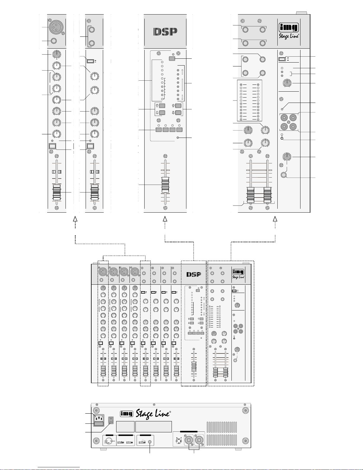
2.1 Frontplatte (Abb. 1)
A Mono-Eingangskanal „1”
(die übrigen drei Mono-Eingangskanäle sind identisch)
Stereo-Eingangskanal „5-6”
(die übrigen drei Stereo-Eingangskanäle sind identisch)
1 Eingang „MIC” (XLR, sym.) für den Anschluss
eines Mono-Mikrofons
2 Stereo-Eingang „LINE” (6,3-mm-Klinke, asym.)
für den Anschluss einer Stereo-Signalquelle mit
Line-Ausgangspegel (z.B. Mini-Disk-Recorder,
CD-Spieler, Keyboard, Drumcomputer)
(Bei Anschluss einer Mono-Signalquelle die obere Buchse „LEFT” verwenden.)
Please unfold page 3. Then you can always see the
operating elements and connections described.
Contents
1 Applications . . . . . . . . . . . . . . . . . . . . . . . . 4
2 Operating Elements and Connections . . 4
2.1 Front panel . . . . . . . . . . . . . . . . . . . . . . . . . 4
2.2 Rear panel . . . . . . . . . . . . . . . . . . . . . . . . . 6
3 Safety Notes . . . . . . . . . . . . . . . . . . . . . . . 6
4 Setting-up/Rack Installation . . . . . . . . . . 7
5 Connections . . . . . . . . . . . . . . . . . . . . . . . 7
5.1 Input channels . . . . . . . . . . . . . . . . . . . . . . .7
5.2 Inserting an effect unit . . . . . . . . . . . . . . . . .7
5.2.1 Effect way “FX” . . . . . . . . . . . . . . . . . . . . . 7
5.2.2 Insert jacks . . . . . . . . . . . . . . . . . . . . . . . . 8
5.3 Connecting headphones and monitoring
system . . . . . . . . . . . . . . . . . . . . . . . . . . . . .8
5.4 Connecting a sound recorder . . . . . . . . . . . 8
5.5 Master output “MAIN OUT” . . . . . . . . . . . . . 8
5.6 Connecting speakers . . . . . . . . . . . . . . . . . 8
5.7 Connecting a footswitch . . . . . . . . . . . . . . . 9
5.8 Power supply . . . . . . . . . . . . . . . . . . . . . . . . 9
6 Operation . . . . . . . . . . . . . . . . . . . . . . . . . . 9
6.1 Basic adjustment of input channels . . . . . . . 9
6.2 Mixing the audio sources . . . . . . . . . . . . . . 9
6.2.1 Inputs “AUX INPUT” and “TAPE PLAY” . 10
6.3 Using the internal effect processor (“DSP”) 10
6.3.1 Storing effect adjustments . . . . . . . . . . . 11
6.4 Adjustments for an effect unit inserted into
the effect way “FX” . . . . . . . . . . . . . . . . . . 11
6.5 Adjustments for the monitor way . . . . . . . . 11
6.6 Monitoring via headphones . . . . . . . . . . . . 11
6.6.1 Prefader listening (“PFL”)
to an input channel . . . . . . . . . . . . . . . . . 11
6.6.2 Monitoring the master signal . . . . . . . . . 12
6.7 Warning indications of the power amplifier 12
7 Modifications . . . . . . . . . . . . . . . . . . . . . . 12
7.1 Modifying send ways . . . . . . . . . . . . . . . . .13
7.2 Switching off the phantom power for indi-
vidual channels . . . . . . . . . . . . . . . . . . . . . 13
8 Specifications . . . . . . . . . . . . . . . . . . . . . 13
Annex: Block diagram . . . . . . . . . . . . . . 30
1 Applications
The power mixer PMX-400DSP combines an 8channel mixer and a stereo power amplifier of 2 x
200W
RMS. It has specially been designed for musi-
cians and applications on stage.
The 8 input channels – 4 mono channels, 4 stereo channels – allow connection of microphones
(also phantom powered microphones) and units with
line level (e.g. CD player, musical instrument, tape
recorder). Each input channel is provided with an
equalizer: 2-way equalizer for the stereo channels,
3-way equalizer with semi-parametric midrange
control for the mono channels. The unit is equipped
with a “prefader” monitor way and a “post fader”
effect way (to be switched internally, if required –
see chapter 7.1) and additionally with an internal
effect processor (“DSP” = Digital Signal Processor).
In addition, insert jacks allow insertion of another
unit into the master signal. Each input channel can
be monitored with headphones via the prefader
listening facility “PFL”.
2 Operating Elements and Connections
2.1 Front panel (fig. 1)
A Mono input channel “1”
(identical to the other three mono input channels)
Stereo input channel “5-6”
(identical to the other three stereo input channels)
1 Input “MIC” (XLR, bal.) for connecting a mono
microphone
2 Stereo input “LINE” (6.3mm jack, unbal.) for
connecting a stereo signal source with line output level (e.g. minidisk recorder, CD player, keyboard, drum computer)
(When connecting a mono signal source, use the
upper jack “LEFT”.)
3 Mono input “LINE” (6.3 mm jack, bal.) for con-
necting a mono signal source with line output
4
GB
D
A
CH

3 Mono-Eingang „LINE” (6,3-mm-Klinke, sym.) für
den Anschluss einer Mono-Signalquelle mit LineAusgangspegel, z.B. Musikinstrument, Empfänger eines drahtlosen Mikrofonsystems
4 Regler „GAIN” zum Einstellen der Eingangsver-
stärkung
5 Umschalttaste „GAIN” zum Einstellen der Ein-
gangsverstärkung
Taste nicht gedrückt ( „LO”)
niedrige Verstärkung für professionelle Geräte
mit einem Ausgangspegel von +4dBu (z.B.
CD-Spieler)
Taste gedrückt ( „HI”)
höhere Verstärkung für semiprofessionelle Geräte mit einem Ausgangspegel von
-
10dBu
(z.B. Keyboard)
6 Höhenregler
7 Regler zum Einstellen der Filterfrequenz für die
Klangregelung im Mittenbereich
8 Mittenregler
9 Tiefenregler
10 Effekt-Send-Regler „DSPFX” zum Einstellen des
Pegels, mit dem das Kanalsignal
a auf den internen Effektprozessor und
b auf den Effekt-Ausspielweg „FX”
gemischt wird; das Signal wird nach dem Kanalfader („Post Fader”) abgegriffen
Hinweis: Der Signalabgriffspunkt kann intern für
jeden Kanal getrennt von „Post Fader”
auf „Pre Fader” umgestellt werden –
siehe Kap. 7.1.
11 Monitor-Send-Regler „MON” zum Einstellen des
Pegels, mit dem das Kanalsignal auf den Monitor-Ausspielweg gemischt wird; das Signal wird
vor dem Kanalfader („Pre Fader”) abgegriffen
Hinweis: Der Signalabgriffspunkt kann intern für
jeden Kanal getrennt von „Pre Fader”
auf „Pre Equalizer” oder „Post Fader”
umgestellt werden – siehe Kap. 7.1.
12 Panoramaregler zum Verteilen des Mono-Kanal-
signals auf die Stereo-Basis
13 Balanceregler zur Einstellung des Pegelverhält-
nisses vom linken und rechten Kanal
14 Anzeige „PEAK”
a Ist die Vorhörfunktion für den Kanal nicht akti-
viert [PFL-T aste (15) nicht gedrückt], zeigt kurzes Aufleuchten der LED an, dass das Kanalsignal einen Maximalpegel erreicht hat, bei
dem es gerade noch nicht übersteuert wird.
b Ist die Vorhörfunktion für den Kanal aktiviert
[PFL-Taste (15) gedrückt], leuchtet die LED
permanent.
15 PFL-Taste zum V orhören des Kanals („ Pre Fader
Listening”) über einen an der Buchse „PHONES”
(45) angeschlossenen Kopfhörer
16 Pegelregler (Fader) des Kanals
B Effektsektion („DSP”)
(nähere Informationen zu den wählbaren Effekten und ihren
Parametern siehe Kap. 6.3)
17 LED-Reihe zur Anzeige des mit den Effektwahl-
tasten (18) eingestellten Effekts
18 Pfeiltasten und zur Effektauswahl (9 Ef-
fekte mit einstellbarem Parameter und 1 Spezialeffekt mit festem Parameter)
19 Speichertasten „1” bis „4” zum Abspeichern von
bis zu vier Effekteinstellungen:
1. entsprechende Speichertaste drücken (LED
darüber leuchtet)
2. Effekt und Effekt-Parameter wählen [mit den
Tasten und (18) und (23)]
3. Speichertaste erneut drücken (LED erlischt):
der Effekt ist abgespeichert und kann durch
Drücken der Taste abgerufen werden
20 Fader zum Mischen des über den internen Effekt-
prozessor erzeugten Effektsignals auf die Signalsumme
21 Taste zum Ein-/Ausschalten des internen Effekt-
prozessors, mit Kontrollanzeige
22 LED-Reihe „TIME” zur Anzeige des gewählten
Spezialeffekts (siehe Kap. 6.3, Tabelle 2) bzw.
zur Anzeige des eingestellten Effekt-Parameters
23 Pfeiltasten und zum Auswählen des Spe-
zialeffekts (7 Spezialeffekte auswählbar, siehe
Kap. 6.3, Tabelle 2) bzw. zum Einstellen des
Parameters für den gewählten Effekt
24 LED „DSP PEAK”; zeigt an, dass sich das Ein-
gangssignal für den internen Effektprozessor
kurz vor der Übersteuerung befindet
C Mastersektion
25 Stereo-Masterausgang „MAIN OUT” (6,3-mm-
Klinke, sym.) zum Herausführen der Signalsumme aus dem Power Mixer, z.B. für den Anschluss
eines weiteren Mischpults oder Verstärkers
26 Insert-Buchsen Links/Rechts zum Einschleifen
eines Effektgerätes (z.B. grafischer Equalizer) in
die Signalsumme; zum Anschluss des Effektgerätes siehe Kap. 5.2.2
27 Effekt-Send-Ausgang „FX” (6,3-mm-Klinke, asym.)
zum Herausführen der auf den Effektweg gemischten Signale; hier kann der Eingang eines
Effektgeräts (z.B. Kompressor) angeschlossen
werden
28 Stereo-Return-Eingang „AUX INPUT” (6,3-mm-
Klinke, asym.) zum Zurückführen von Signalen,
die über den Ausgang „FX” (27) aus dem Power
Mixer herausgeführt und durch ein Effektgerät
geschleift wurden; der Eingang kann bei Bedarf
auch zum Anschluss einer weiteren Signalquelle
mit Line-Ausgangspegel, z.B. CD-Spieler, zweites Mischpult, genutzt werden
(Bei Anschluss eines Mono-Geräts die obere
Buchse „LEFT” verwenden.)
29 Monitorausgang „MON” (6,3-mm-Klinke, asym.)
zum Herausführen der auf den Monitorweg gemischten Signale; hier kann der Endverstärker
einer Monitoranlage angeschlossen werden
30 Aussteuerungsanzeige mit PPM-Charakteristik
(Peak Program Meter = Spitzenwertmesser);
zeigt entweder den Masterpegel oder den „Pre
Fader”-Pegel des Eingangskanals, dessen Taste
„PFL” (15) gedrückt ist
level, e.g. musical instrument, receiver of a wireless microphone system
4 “GAIN” control for adjusting the input amplifica-
tion
5 “GAIN” selector for adjusting the input amplifica-
tion
button not pressed ( “LO”)
low amplification for professional units with an
output level of +4dBu (e.g. CD player)
button pressed ( “HI”)
higher amplification for semiprofessional units
with an output level of
-
10dBu (e.g. keyboard)
6 High frequency control
7 Control for adjusting the filter frequency for the
equalizer in the midrange
8 Midrange control
9 Low frequency control
10 Effect send control “DSP FX” for adjusting the
level at which the channel signal is mixed
a to the internal effect processor and
b to the effect send way “FX”;
the signal is picked up after the channel fader
(“post fader”).
Note: The signal pick-up point can be switched inter-
nally from “post fader” to “prefader”, separately for each channel – see chapter 7.1.
11 Monitor send control “MON” for adjusting the
level at which the channel signal is mixed to the
monitor send way; the signal is picked up ahead
of the channel fader (“prefader”)
Note: The signal pick-up point can be switched
internally from “prefader” to “pre-equalizer” or
“post fader”, separately for each channel
– see chapter 7.1.
12 Panorama control for distributing the mono chan-
nel signal on the stereo base
13 Balance control for adjusting the level ratio be-
tween the left channel and the right channel
14 LED “PEAK”
a If the prefader listening facility has not been
activated for this channel [PFL button (15) not
pressed], the LED lights up shortly to indicate
that the channel signal has reached its maximum level just before being overloaded.
b If the prefader listening facility has been
activated for this channel [PFL button (15)
pressed], the LED lights continuously.
15 PFL button for prefader listening to the channel
via headphones connected to the jack “PHONES”
(45)
16 Level control (fader) of the channel
B Effect section (“DSP”)
(for detailed information on the effects to be selected and
their parameters see chapter 6.3)
17 LED row for indicating the effect adjusted with
the effect selection keys (18)
18 Arrow keys and for effect selection
(9 effects with adjustable parameter and 1 special effect with fixed parameter)
19 Memory buttons “1” to “4” for storing up to four
effect adjustments:
1. press the corresponding memory button (LED
above the button lights up)
2. select the effect and the effect parameter [use
the keys and (18) and (23)]
3. press the memory button once again (LED is
extinguished): the effect is stored and can be
called by pressing the button
20 Fader for mixing the effect signal produced via
the internal effect processor to the master signal
21 Button for switching on or off the internal effect
processor, with indicating LED
22 LED row “TIME” for indicating the selected spe-
cial effect (see chapter 6.3, table 2) or for indicating the adjusted effect parameter
23 Arrow keys and for selecting the special
effect (7 special effects to be selected, see chapter 6.3, table 2) or for adjusting the parameter for
the selected effect
24 LED “DSP PEAK”; for indicating that the input
signal for the internal effect processor is close to
overload
C Master section
25 Stereo master output “MAIN OUT” (6.3mm jack,
bal.) for routing the master signal out of the
power mixer, e. g. for connecting another mixer
or amplifier
26 Insert jacks Left /Right for inserting an effect unit
(e. g. graphic equalizer) into the master signal;
for connection see chapter 5.2.2
27 Effect send output “FX” (6.3mm jack, unbal.) for
routing out the signals mixed to the effect way;
the input of an effect unit (e.g. compressor) can
be connected to this output
28 Stereo return input “AUX INPUT” (6.3 mm jack,
unbal.) for returning signals routed out of the
power mixer via the output “FX” (27) and fed
through an effect unit; if required, the input can
also be used for connecting another signal
source with line output level, e. g. CD player,
second mixer
(When connecting a mono unit, use the upper
jack “LEFT”.)
29 Monitor output “MON” (6.3 mm jack, unbal.) for
routing out the signals mixed to the monitor way;
the power amplifier of a monitoring system can
be connected to this output
30 Peak Program Meter (PPM); shows either the
master level or the “prefader” level of the input
channel of which the “PFL” button (15) is pressed
31 Effect send master control “FX OUT” [level control
for the master signal of all channel signals taken
off with the controls “DSP FX” (10)]; serves for
a level adjustment of the input signal for the
internal effect processor
b level adjustment of the output signal at the
jack “FX” (27)
32 Level control “AUX IN” for the unit connected to
the input “AUX INPUT” (28)
33 Level control “DSP TO MON” for mixing the
effect signals produced via the internal effect
processor to the monitor way
5
GB
D
A
CH

31 Effekt-Send-Summenregler „FX OUT” [Pegelreg-
ler für die Summe aller mit den Reglern „DSP FX
(10) ausgekoppelten Kanalsignale]; dient
a zur Pegeleinstellung des Eingangssignals für
den internen Effektprozessor
b zur Pegeleinstellung des Ausgangssignals an
der Buchse „FX” (27)
32 Pegelregler „AUX IN” für das am Eingang „AUX
INPUT” (28) angeschlossene Gerät
33 Pegelregler „DSP TO MON” zum Mischen des
über den internen Effektprozessor erzeugten
Effektsignals auf den Monitorweg
34 Monitor-Send-Summenregler „MON OUT” zur
Pegeleinstellung des Ausgangssignals an der
Buchse „MON” (29)
35 Pegelregler Links/Rechts für das Stereo-Master-
signal, das auf die Endstufe des Power Mixers,
den Masterausgang „MAIN OUT” (25) und den
Aufnahmeausgang „TAPE REC” (41) gegeben
wird
36 Taste „LOUDNESS” für die Endstufe zur Klang-
korrektur (Anheben der Bässe und Höhen) bei
geringen Lautstärken unter Berücksichtigung der
subjektiv empfundenen Lautstärke des menschlichen Gehörs
37 Überhitzungsanzeige „THERMAL”:
bei Überhitzung der Endstufe schaltet sich diese
zum Schutz aus und die Überhitzungsanzeige
leuchtet. Nach ausreichender Abkühlung schaltet
die Endstufe sich wieder automatisch ein und die
Anzeige erlischt.
38 Übersteuerungsanzeige „CLIP” für den linken
und rechten Kanal der Endstufe
39 Pegelregler für die Endstufe
40 Betriebsanzeige
41 Stereo-Aufnahmeausgang „TAPE REC” (Cinch,
asym.) zum Anschluss an den Eingang eines
Tonaufnahmegerätes; der Aufnahmepegel ist
abhängig von den Masterreglern (35)
42 Stereo-Wiedergabeeingang „TAPE PLA Y” (Cinch,
asym.) zum Anschluss an den Ausgang eines
Tonaufnahmegerätes
43 versenkter Schalter (mit Kontrollanzeige) zum
zentralen Zuschalten der 48-V-Phantomspeisung
für alle Buchsen „MIC” (1); erforderlich beim Anschluss von Kondensator- oder Elektretmikrofonen, die mit 48-V-Phantomspeisung arbeiten
Den Schalter mit einem spitzen Gegenstand,
z.B. Kugelschreiber, herunterdrücken.
Hinweis: Die Phantomspeisung kann intern für
einzelne Mono-Kanäle abgeschaltet
werden – siehe Kap. 7.2.
44 Pegelregler „PHONES” für den Kopfhöreraus-
gang (45)
45 Anschluss „PHONES” (6,3-mm-Klinke) für einen
Stereo-Kopfhörer (Impedanz mindestens 2 x 8Ω)
2.2 Rückseite (Abb. 2)
46 Netzbuchse zum Anschluss an eine Steckdose
(230V~/50Hz) über das beiliegende Netzkabel
47 Sicherungshalter; eine durchgebrannte Netzsi-
cherung nur durch eine gleichen Typs ersetzen
48 Ein-/Ausschalter „POWER”
49 Anschlussbuchse (6,3-mm-Klinke, 2polig) für
einen Fußschalter zum Ein-/Ausschalten des
internen Effektprozessors
50 Stereo-Ausgang (Speakon-Buchsen) der End-
stufe für den Anschluss von Lautsprechern
Zum Anschluss der Lautsprecher siehe Kap. 5.6.
3 Hinweise für den sicheren Gebrauch
Dieses Gerät entspricht der Richtlinie für elektromagnetische Verträglichkeit 89/336/EWG und der Niederspannungsrichtlinie 73/23/EWG.
Beachten Sie unbedingt die folgenden Punkte:
●
Das Gerät ist nur zur Verwendung in Innenräumen
geeignet. Schützen Sie es vor Tropf- und Spritzwasser, hoher Luftfeuchtigkeit und Hitze (zulässiger Einsatztemperaturbereich 0–40°C).
●
Stellen Sie keine mit Flüssigkeit gefüllten Gefäße,
z.B. Trinkgläser, auf das Gerät.
●
Die im Gerät entstehende Wärme muss durch
Luftzirkulation abgegeben werden. Decken Sie
die Lüftungsöffnungen nicht mit irgendwelchen
Gegenständen ab.
●
Stecken Sie nichts durch die Lüftungsöffnungen.
Dies kann zu einem elektrischen Schlag führen!
●
Nehmen Sie das Gerät nicht in Betrieb bzw. ziehen
Sie sofort den Netzstecker aus der Steckdose:
1. wenn sichtbare Schäden am Gerät oder an der
Netzanschlussleitung vorhanden sind,
2. wenn nach einem Sturz oder Ähnlichem der
Verdacht auf einen Defekt besteht,
3. wenn Funktionsstörungen auftreten.
Lassen Sie das Gerät in jedem Fall in einer Fachwerkstatt reparieren.
●
Ziehen Sie den Netzstecker nie an der Zuleitung
aus der Steckdose.
●
Verwenden Sie zum Reinigen nur ein trockenes,
weiches Tuch, niemals Wasser oder Chemikalien.
●
Wird das Gerät zweckentfremdet, falsch bedient
oder nicht fachgerecht repariert, kann für eventuelle
Schäden keine Haftung übernommen werden.
●
Soll das Gerät endgültig aus dem Betrieb genommen werden, übergeben Sie es zur umweltgerechten Entsorgung einem örtlichen Recyclingbetrieb.
Achtung!
Das Gerät wird mit lebensgefährlicher Netzspannung (230V~) versorgt. Nehmen Sie nie selbst Eingriffe im Gerät vor. Durch unsachgemäßes Vorgehen besteht die Gefahr eines elektrischen Schlages.
Achtung! Die Gesamtimpedanz der pro Kanal
angeschlossenen Lautsprecher darf
4Ω nicht unterschreiten, sonst kann
die Endstufe beschädigt werden.
Achtung! Bei eingeschalteter Phantomspei-
sung dürfen an den Mikrofoneingängen keine asymmetrischen Mikrofone angeschlossen sein, da diese
zerstört werden könnten.
34 Monitor send master control “MON OUT” for
level adjustment of the output signal at the jack
“MON” (29)
35 Level control Left/Right for the stereo master
signal fed to the power amplifier of the power
mixer, to the master output “MAIN OUT” (25) and
to the recording output “TAPE REC” (41)
36 Button “LOUDNESS” for the power amplifier for
sound correction (boosting of bass frequencies
and high frequencies) at low volumes under consideration of the subjective loudness of noise
37 Overheating LED “THERMAL”
When the power amplifier of the power mixer is
overheated, it switches off for protection and the
overheating LED lights up. After sufficient cooling, the power amplifier is switched on again
automatically and the LED is extinguished.
38 Overload LED “CLIP” for the left and right chan-
nels of the power amplifier
39 Level control for the power amplifier
40 Power LED
41 Stereo recording output “TAPE REC” (phono,
unbal.) for connecting to the input of a sound
recorder; the recording level depends on the
master controls (35)
42 Stereo replay input “TAPE PLA Y” (phono, unbal.)
for connecting the output of a sound recorder
43 Recessed switch (with indicating LED) for central
connection of the 48 V phantom power for all
jacks “MIC” (1); required when connecting
capacitor microphones or electret microphones
operating at 48V phantom power
Depress the button with a pointed object, e. g.
ball pen.
Note: The phantom power can be switched off
internally for individual mono channels
– see chapter 7.2.
44 Level control “PHONES” for the headphone out-
put (45)
45 Connection “PHONES” (6.3 mm jack) for stereo
headphones (minimum impedance 2 x 8Ω)
2.2 Rear panel (fig. 2)
46 Mains jack for connection to a mains socket
(230V~/50 Hz) via the supplied mains cable
47 Fuse holder; always replace a burnt-out fuse by
one of the same type only
48 “POWER” switch
49 6.3mm jack, 2-pole for a footswitch for switching
on or off the internal effect processor
50 Stereo output (Speakon jacks) of the power
amplifier for connecting speakers
For connecting the speakers see chapter 5.6.
3 Safety Notes
This unit corresponds to the directive for electromagnetic compatibility 89/ 336 /EEC and to the low
voltage directive 73/23/EEC.
Please observe the following items in any case:
● The unit is suitable for indoor use only. Protect it
against dripping water and splash water, high air
humidity, and heat (admissible ambient temperature range 0–40°C).
● Do not place any vessel filled with liquid on the
unit, e.g. a drinking glass.
● The heat generated within the unit must be carried
off by air circulation. Do not cover the air vents of
the housing with any objects.
● Do not insert anything into the air vents. This may
result in an electric shock!
● Do not operate the unit or immediately disconnect
the plug from the mains socket
1. if there is visible damage to the unit or to the
mains cable,
2. if a defect might have occurred after the unit
was dropped or suffered a similar accident,
3. if malfunctions occur.
In any case the unit must be repaired by skilled
personnel.
● Never pull the mains cable for disconnecting the
mains plug from the socket.
● For cleaning only use a dry, soft cloth, by no
means chemicals or water.
● No liability for any damage will be accepted if the
unit is used for other purposes than originally
intended, if it is not correctly connected, operated,
or not repaired in an expert way.
● If the unit is to be put out of operation definitively,
take it to a local recycling plant for a disposal
which is not harmful to the environment.
●
Important for U.K. Customers!
The wires in this mains lead are coloured in accordance with the following code:
green/yellow = earth
blue = neutral
brown = live
As the colours of the wires in the mains lead of this
appliance may not correspond with the coloured
markings identifying the terminals in your plug,
proceed as follows:
Attention!
The unit is supplied with hazardous mains voltage
(230V~). Leave servicing to skilled personnel only.
Inexpert handling may cause an electric shock
hazard.
Attention! The total impedance of the speak-
ers connected per channel must not
fall below 4Ω, otherwise the power
amplifier may be damaged.
Attention! With the phantom power switched
on, no unbalanced microphones
must be connected to the microphone inputs as they might be destroyed.
6
GB
D
A
CH
4 Aufstellung/Rack-Montage
Das Gerät lässt sich sowohl als Tischgerät verwenden als auch in ein Rack (482mm/19") einbauen. In
jedem Fall muss Luft ungehindert durch alle Lüftungsöffnungen strömen können, damit eine ausreichende Kühlung der Endstufe gewährleistet ist.
Bei Verwendung als Tischgerät können die beiliegenden Kunststoff-Seitenteile montiert werden. Die
Seitenteile mit jeweils 2 Schrauben (mitgeliefert)
links und rechts am Gerät anbringen (siehe Abb. 3).
➂
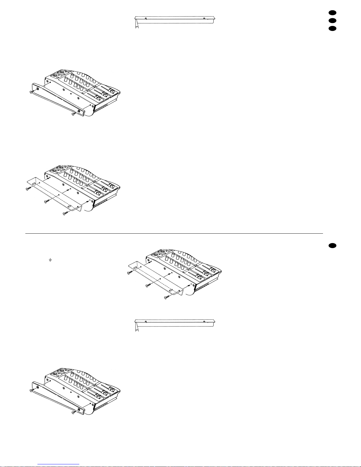
Montage des linken Seitenteils
Für den Rackeinbau des Geräts die beiliegenden
Rackhalterungen inkl. Schrauben verwenden. Die
Halterungen mit jeweils 3 Schrauben links und
rechts am Gerät anbringen (siehe Abb. 4). Jede
Halterung so anbringen, dass ihr abgewinkeltes
Ende nach hinten zeigt (siehe auch Abb. 5).
➃
Montage der linken Rackhalterung
➄
linke Rackhalterung
Beim Einbau des Geräts in ein Rack darauf achten,
dass das Rack nicht zu kopflastig und damit instabil
wird. Ein mechanisch sicherer und stabiler Rackaufbau muss gewährleistet sein.
5 Anschlüsse
Vor dem Anschließen von Geräten an den Power
Mixer bzw. vor dem Ändern bestehender Anschlüsse den Power Mixer und alle anderen Audio-Geräte
ausschalten.
5.1 Eingangskanäle
Die Tonquellen an die entsprechenden Buchsen der
Eingangskanäle anschließen:
-
Mikrofone bzw. andere niederohmige Mono-Signalquellen mit geringen Ausgangspegeln an die
Buchsen „MIC” (1)
-
Mono-Geräte mit Line-Pegel (z.B. Empfänger
eines drahtlosen Mikrofonsystems, Musikinstrument) an die Mono-Eingänge „LINE” (3) oder an
die obere Buchse „LEFT” der Stereo-Eingänge
„LINE” (2)
-
Stereo-Geräte mit Line-Pegel (z.B. Synthesizer,
Keyboard, Drumcomputer, CD-Spieler) an die
Stereo-Eingänge „LINE” (2):
obere Buchse „LEFT” = linker Kanal,
untere Buchse „RIGHT” = rechter Kanal
Auch der Stereo-Eingang „AUX INPUT” (28) kann
bei Bedarf für den Anschluss einer Line-Tonquelle
genutzt werden (bei Anschluss eines Mono-Geräts
die obere Buchse „LEFT” verwenden). Das Signal
des an diesen Buchsen angeschlossenen Geräts
wird mit dem Regler „AUX IN” (32) auf die Stereosumme gemischt.
5.2 Effektgerät einschleifen
Es gibt zwei Möglichkeiten, ein Effektgerät (z.B.
grafischer Equalizer, Noise-Gate, Kompressor) einzuschleifen:
1. in dem der Effektweg „FX” des Power Mixers
genutzt wird – siehe Kap. 5.2.1
2. über die Insert-Buchsen (26) – siehe Kap. 5.2.2
5.2.1 Effektweg „FX”
Mit den Effekt-Send-Reglern „DSP FX” (10)* lassen
sich die Eingangskanäle „1” bis „11-12” einzeln auf
den Effektweg legen; der Effektweg ist „Post Fader”
geschaltet, d. h. das Kanalsignal wird nach dem jeweiligen Kanalfader (16) abgegriffen. (Der Signalabgriffspunkt kann intern für jeden Kanal getrennt auf
„Pre Fader” umgestellt werden – siehe dazu Kap. 7.1
„Ausspielwege modifizieren”.) Das Gesamtsignal des
Effektweges steht am Effekt-Send-Ausgang „FX” (27)
zur Verfügung und kann einem Effektgerät zugeführt
werden; der Ausgangspegel wird mit dem EffektSend-Summenregler „FX OUT” (31)* eingestellt.
Das durch das Effektgerät bearbeitete Signal
wird über den Eingang „AUX INPUT” (28) wieder in
den Power Mixer zurückgeführt und mit dem Regler
„AUX IN” (32) auf die Signalsumme gemischt.
1) Den Eingang des Effektgerätes an die Mono-Ausgangsbuchse „FX” (27) anschließen.
2) Den Ausgang des Effektgerätes an den StereoEingang „AUX INPUT” (28) anschließen (bei Anschluss eines Mono-Gerätes nur die obere Buchse „LEFT” verwenden).
*Die Regler „DSPFX” (10) und „FX OUT” (31) bestimmen sowohl
das Ausgangssignal an der Buchse „FX” (27) als auch das Eingangssignal für den internen Effektprozessor des Power Mixers
(siehe Kap. 6.3).
5.2.2 Insert-Buchsen
Das Stereo-Summensignal lässt sich – noch vor den
Masterfadern (35) – über die Insert-Buchsen (26)
auskoppeln, durch ein Stereo-Effektgerät schleifen
und über dieselben Buchsen wieder in den Power
Mixer zurückführen.
1. The wire which is coloured green and yellow
must be connected to the terminal in the plug
which is marked with the letter E or by the earth
symbol , or coloured green or green and yel-
low.
2. The wire which is coloured blue must be connected to the terminal which is marked with the
letter N or coloured black.
3. The wire which is coloured brownmust be connected to the terminal which is marked with the
letter L or coloured red.
Warning
-
This appliance must be earthed.
4 Setting-up/Rack Installation
The unit can either be used as a table top unit or can
be installed into a rack (482 mm /19"). In any case,
air must be allowed to pass through all air vents to
ensure sufficient cooling of the power amplifier.
If the unit is used as a table top unit, the supplied
plastic side parts can be mounted. Fasten the side
parts with 2 screws each (supplied) to the left and
right sides of the unit (see fig. 3).
➂
Mounting the left side part
For rack installation of the unit, use the supplied
rack supports including the screws. Mount the supports with 3 screws each on the left and right sides
of the unit (see fig. 4). Each support must be mounted in such a way that its angled end points to the
rear (also see fig. 5).
➃
Mounting the left rack support
➄
left rack support
When installing the unit into a rack, observe that the
rack is not top heavy and thus instable. Amechanically
safe and stable rack installation must be ensured.
5 Connections
Prior to connecting units to the power mixer or to
changing existing connections, switch off the power
mixer and all other audio units.
5.1 Input channels
Connect the audio sources to the corresponding
jacks of the input channels:
-
microphones or other low impedance mono signal sources with low output levels to the jacks
“MIC” (1)
-
mono units with line level (e.g. receiver of a wireless microphone system, musical instruments) to
the mono inputs “LINE” (3) or to the upper jack
“LEFT” of the stereo inputs “LINE” (2)
-
stereo units with line level (e.g. synthesizer, keyboard, drum computer, CD player) to the stereo
inputs “LINE” (2):
If required, the stereo input “AUX INPUT” (28) can
also be used for connecting a line audio source
(when connecting a mono unit, use the upper jack
“LEFT”). The signal of the unit connected to these
jacks is mixed to the stereo master with the control
“AUX IN” (32).
5.2 Inserting an effect unit
Two possibilities exist for inserting an effect unit
(e.g. graphic equalizer, noise gate, compressor):
1. by using the effect way “FX” of the power mixer
– see chapter 5.2.1
2. via the insert jacks (26) – see chapter 5.2.2
5.2.1 Effect way “FX”
With the effect send controls “DSP FX” (10)*, the
input channels “1” to “11-12” can be individually sent
to the effect way; the effect way is provided with
“post fader” wiring, i.e. the channel signal is picked
up after the corresponding channel fader (16). (The
signal pick-up point can be switched internally to
“prefader”, separately for each channel – see chapter 7.1 “Modifying send ways”.) The master signal of
the effect way is available at the effect send output
“FX” (27) and can be fed to an effect unit; the output
level is adjusted with the effect send master control
“FX OUT” (31)*.
The signal processed by the effect unit is returned to the power mixer via the input “AUX INPUT”
(28) and then mixed to the master signal with the
control “AUX IN” (32):
1) Connect the input of the effect unit to the mono
output jack “FX” (27).
2) Connect the output of the effect unit to the stereo
input “AUX INPUT” (28) [when connecting a
mono unit, only use the upper jack “LEFT”].
* The controls “DSP FX” (10) and “FX OUT” (31) define both the
output signal at the jack “FX” (27) and the input signal for the
internal effect processor of the power mixer (see chapter 6.3).
7
GB
D
A
CH
hinten vorn
rear front
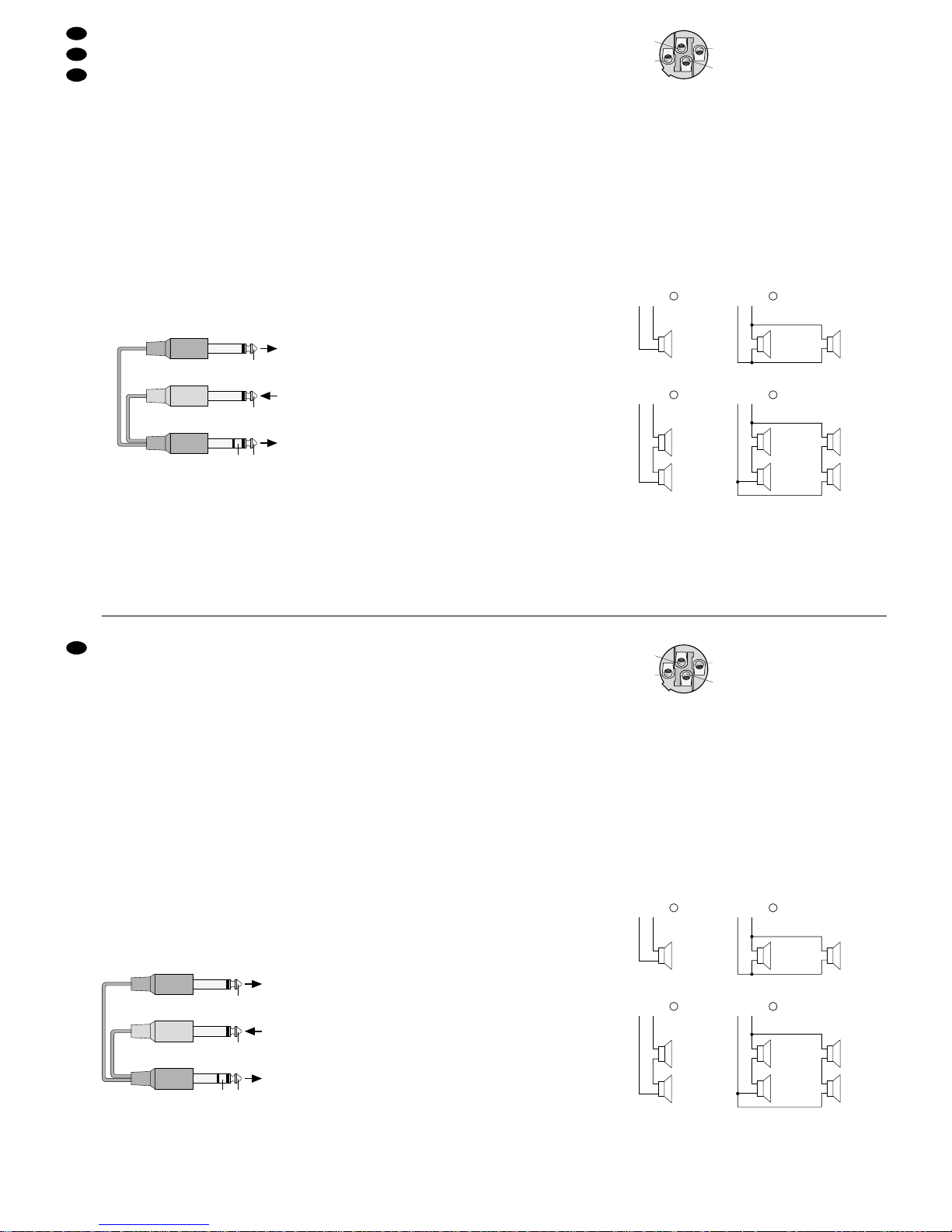
Für den Anschluss des Effektgeräts je ein Y-Kabel
(1 Stereo-Klinkenstecker auf 2 Mono-Klinkenstecker)
für den linken und den rechten Kanal verwenden.
Aus dem Programm von MONACOR eignet sich
dazu das Kabel MCA-202. Zum Anschluss des Kabels siehe auch Abb. 6.
1) Für den linken Kanal den Stereo-Stecker eines
Y-Kabels in die linke Insert-Buchse „L” stecken.
Das zum Effektgerät gehende Ausgangssignal
(„Send”) liegt an der Spitze des Stereo-Steckers
an, das vom Effektgerät kommende Eingangssignal („Return”) am Ring; am Schaft liegt die
gemeinsame Masse an.
Den Mono-Stecker für das Send-Signal an
den linken Eingangskanal des Effektgeräts anschließen und den Mono-Stecker für das ReturnSignal an den linken Ausgangskanal des Effektgeräts.
2) Das zweite Y-Kabel auf die gleiche Weise an die
rechte Insert-Buchse „R” und den rechten Einund Ausgangskanal des Effektgeräts anschließen.
➅
Anschluss des Y-Kabels MCA-202 von MONACOR
5.3 Kopfhörer und Monitoranlage anschließen
Beim Abmischen kann sowohl das Mastersignal als
auch das PFL-Signal jedes Eingangskanals über
einen Stereo-Kopfhörer (Impedanz min. 2 x 8 Ω)
abgehört werden (siehe dazu Kap. 6.6). Den Kopfhörer an die Buchse „PHONES” (45) anschließen.
Der Monitorweg des Power Mixers bietet den
Musikern die Möglichkeit, das Musiksignal über eine
Monitoranlage auf der Bühne abzuhören. Mit den
Reglern „MON” (11) lassen sich die Eingangskanäle
„1” bis „11-12” einzeln auf den Monitorweg mischen;
der Monitorweg ist „Pre Fader” geschaltet, d.h. das
Kanalsignal wird noch vor dem jeweiligen Kanalfader (16) abgegriffen. (Der Signalabgriffspunkt kann
intern für jeden Kanal getrennt auf „Pre Equalizer”
oder „Post Fader” umgestellt werden – siehe dazu
Kap. 7.1 „Ausspielwege modifizieren”.) Den Endverstärker der Monitoranlage an den Ausgang „MON”
(29) anschließen: hier liegt das Gesamtsignal des
Monitorwegs an; der Ausgangspegel wird mit dem
Regler „MON OUT” (34) eingestellt.
5.4 Tonaufnahmegerät anschließen
Für T onaufnahmen den Eingang eines Tonaufnahmegerätes an die Buchsen „TAPE REC” (41) anschließen. Der Pegel des Aufnahmesignals ist abhängig
von der Einstellung der Masterregler (35).
Für die Wiedergabe den Wiedergabeausgang
des Aufnahmegerätesan den Eingang „T APE PLA Y”
(42) anschließen. Für die Wiedergabe kann auch
ein freier Stereo-Eingangskanal genutzt werden.
Dies bietet die Möglichkeit, den gewünschten Pegel
und Klang des Signals über die entsprechenden
Regler des Kanals einzustellen.
5.5 Masterausgang „MAIN OUT”
Am symmetrischen Stereo-Masterausgang „MAIN
OUT” (25) steht das mit den Masterreglern (35) ausgesteuerte Gesamtsignal zur Verfügung. Hier kann
z. B. der Eingang eines weiteren Verstärkers oder
eines zweiten Mischpultes angeschlossen werden.
5.6 Lautsprecher anschließen
Die Lautsprecher an den Stereo-Ausgang „SPEAKER OUTPUT” (50) anschließen: Buchse „LEFT”
für den linken Kanal, Buchse „RIGHT” für den rechten Kanal.
1+ Lautsprecher Pluspol
1
-
Lautsprecher Minuspol
2+ und 2
-
bleiben frei
➆
Kontaktbelegung am Speakon-Stecker
Bei einem Lautsprecher pro Kanal muss jeder
Lautsprecher eine Impedanz von mindestens 4 Ω
besitzen. 4-Ω-Lautsprecher müssen mit einer SinusAusgangsleistung von mindestens 200 W belastbar
sein. Es können auch 8-Ω-Lautsprecher angeschlossen werden, wobei sich die Ausgangsleistung der
Endstufe jedoch etwas verringert (siehe Abb. 8a)
Bei mehreren Lautsprechern pro Kanal muss
die Gesamtimpedanz pro Kanal mindestens 4Ω
betragen. Achten Sie beim Zusammenschalten von
mehreren Lautsprechern besonders auf die richtige
Verbindung der Plus- und Minusanschlüsse. Die Anschlussmöglichkeiten für mehrere Lautsprecher pro
Kanal sind in den Abb. 8b bis 8d dargestellt.
➇
Lautsprecheranschlussmöglichkeiten
Die Speakon-Stecker in die entsprechenden Buchsen stecken und nach rechts drehen, bis sie einrasten. Zum späteren Herausziehen des Steckers
den Sicherungsriegel am Stecker nach hinten schieben und den Stecker nach links drehen.
Speakon
1-
1+
c
4 Ω: 70 WRMS
4 Ω: 70 WRMS
+
-
+
-
4 Ω: 200 WRMS
8 Ω: 140 WRMS
+
-
Speakon
1-
1+
a
4 Ω: 50 WRMS
8 Ω: 35 WRMS
4 Ω: 50 WRMS
8 Ω: 35 WRMS
4 Ω: 50 WRMS
8 Ω: 35 WRMS
4 Ω: 50 WRMS
8 Ω: 35 WRMS
8 Ω: 100 WRMS
8 Ω: 100 WRMS
+
-
+
-
+
-
+
-
+
-
+
-
Speakon
1-
1+
b
Speakon
1-
1+
d
2
-
2+
1+
1
-
Power Mixer
INSERT
Eingang
Effektgerät
Ausgang
Effektgerät
RETURN SEND
RETURN
SEND
rot
schwarz
schwarz
5.2.2 Insert jacks
The stereo master signal can be taken off – ahead of
the master faders (35) – via the insert jacks (26), fed
through a stereo effect unit and returned to the
power mixer via the same jacks.
For connecting the effect unit, use a Y -cable each
(1 stereo plug to 2 mono plugs) for the left and right
channels. Cable MCA-202 from the MONACOR
range is suitable for this purpose. For connecting the
cable also see fig. 6.
1) For the left channel, connect the stereo plug of a
Y-cable to the left insert jack “L”. The output sig-
nal (“Send”) being sent to the effect unit is at the
tip of the stereo plug, the input signal (“Return”)
returning from the effect unit at the ring; the com-
mon ground is at the shank.
Connect the mono plug for the send signal to
the left input channel of the effect unit and the
mono plug for the return signal to the left output
channel of the effect unit.
2) Connect the second Y-cable in the same way to
the right insert jack “R” and the right input and
output channels of the effect unit.
➅
Connection of the MONACOR Y-cable MCA-202
5.3 Connecting headphones and monitoring
system
When mixing, both the master signal and the PFL
signal of each input channel can be monitored via
stereo headphones (minimum impedance 2 x 8 Ω)
[see chapter 6.6]. Connect the headphones to the
jack “PHONES” (45).
The monitor way of the power mixer enables the
musicians to monitor the music signal via a monitor-
ing system on stage. With the controls “MON” (11),
the input channels “1” to “11-12” can individually be
mixed to the monitor way; the monitor way is provided
with “prefader” wiring, i.e. the channel signal is
picked up ahead of the corresponding channel fader
(16). (The signal pick-up point can be switched internally to “pre-equalizer” or “post fader”, separately for
each channel – see chapter 7.1 “Modifying send
ways”.) Connect the power amplifier of the monitoring
system to the output “MON” (29): that is where the
master signal of the monitor way is applied; the output
level is adjusted with the control “MON OUT” (34).
5.4 Connecting a sound recorder
For audio recordings, connect the input of a sound
recorder to the jacks “TAPE REC” (41). The level of
the recording signal depends on the adjustment of
the master controls (35).
For replay, connect the replay output of the
sound recorder to the input “TAPE PLAY” (42). It is
also possible to use an unconnected stereo input
channel for replay. This allows to adjust the desired
level and sound of the signal via the corresponding
controls of the channel.
5.5 Master output “MAIN OUT”
At the balanced stereo master output “MAIN OUT”
(25), the master signal adjusted with the master controls (35) is available; e.g. the input of another amplifier or second mixer can be connected to this output.
5.6 Connecting speakers
Connect the speakers to the stereo output “SPEAKER
OUTPUT” (50): jack “LEFT” for the left channel, jack
“RIGHT” for the right channel.
1+ positive pole of speaker
1
-
negative pole of speaker
2+ and 2
-
remain unconnected
➆
Pin configuration of the Speakon plug
With one speaker per channel, each speaker must
have a minimum impedance of 4 Ω. 4 Ω speakers
must be capable of an RMS output power of at least
200 W. It is also possible to connect 8Ω speakers,
however, the output power will be slightly reduced in
this case (see fig. 8a).
With several speakers per channel, the total
impedance per channel must be at least 4Ω. When
interconnecting several speakers, attention must be
paid to correct connection of positive and negative
terminals. Figs. 8b to 8d show options for connecting several speakers per channel.
➇
Options for connecting speakers
Connect the Speakon plugs to the corresponding
jacks and turn them clockwise until they lock into
place. For disconnecting the plug later, push the
locking latch on the plug to the rear, then turn the
plug counter-clockwise.
Speakon
1-
1+
c
4 Ω: 70 WRMS
4 Ω: 70 WRMS
+
-
+
-
4 Ω: 200 WRMS
8 Ω: 140 WRMS
+
-
Speakon
1-
1+
a
4 Ω: 50 WRMS
8 Ω: 35 WRMS
4 Ω: 50 WRMS
8 Ω: 35 WRMS
4 Ω: 50 WRMS
8 Ω: 35 WRMS
4 Ω: 50 WRMS
8 Ω: 35 WRMS
8 Ω: 100 WRMS
8 Ω: 100 WRMS
+
-
+
-
+
-
+
-
+
-
+
-
Speakon
1-
1+
b
Speakon
1-
1+
d
2
-
2+
1+
1
-
power mixer
INSERT
input
effect unit
output
effect unit
RETURN SEND
RETURN
SEND
red
black
black
8
GB
D
A
CH
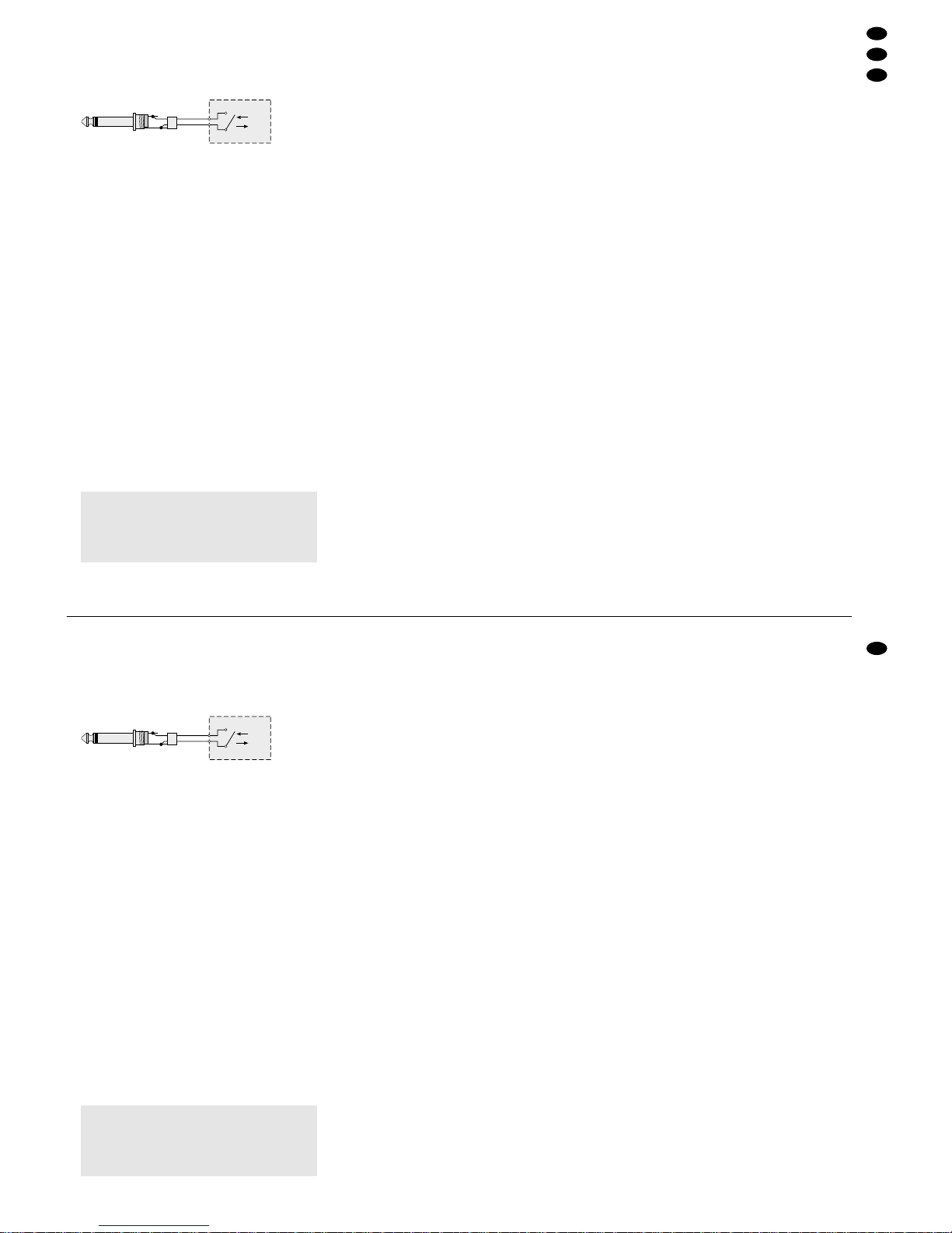
5.7 Fußschalter anschließen
Der interne Effektprozessor kann über einen Fußschalter (z.B. FS-60Avon MONACOR) ein- und ausgeschaltet werden. Den Fußschalter an die Buchse
„DSP FOOTSWITCH” (49) anschließen.
Anschluss für einen Fußschalter
5.8 Stromversorgung
Zum Schluss das mitgelieferte Netzkabel mit dem
Anschluss (46) verbinden und den Netzstecker des
Kabels in eine Steckdose (230V~/50Hz) stecken.
6 Bedienung
1) Vor dem Einschalten sollten der Endstufenregler
„LEVEL” (39), die Masterregler (35) sowie die
Ausgangsregler „FX OUT” (31) und „MON OUT”
(34) auf Minimum gestellt werden, um starke Einschaltgeräusche zu vermeiden.
2) Den Power Mixer mit dem Netzschalter „POWER”
(48) einschalten. Zur Anzeige der Betriebsbereitschaft leuchtet die LED „POWER ON” (40).
3) Bei Verwendung von Kondensator- oder Elektretmikrofonen, die eine 48-V-Phantomspeisung benötigen, den versenkten Schalter „48V PHANTOM POWER” (43) mit Hilfe eines spitzen Gegenstandes (z.B. Kugelschreiber) herunterdrücken. Alle Mikrofoneingänge (1) werden dann mit
einer 48-V-Phantomspeisung versorgt* und die
LED über dem Schalter leuchtet.
* Die Phantomspeisung kann intern für einzelne Kanäle ab-
geschaltet werden – siehe Kap. 7.2.
6.1 Grundeinstellung der Eingangskanäle
Vor dem Auspegeln der Eingangskanäle zuerst
-
zum Ausschalten des internen Effektprozessors
die T aste „DSPON” (21)
drücken, falls der Effektprozessor eingeschaltet ist (wird durch Leuchten der LED über der
Taste angezeigt)
-
alle Gain-Regler (4) der Mono-Eingangskanäle
auf ca.
2
/3 des Maximums aufdrehen
-
alle Gain-Tasten (5) der Stereo-Eingangskanäle
lösen, falls sie gedrückt sind (Position „LO”)
-
alle Klangregler (6, 8, 9)
in die Mittelstellung auf „0” drehen
-
alle Regler (7) zum Einstellen der Filterfrequenz
für die Klangregelung im Mittenbereich (nur für
die Mono-Kanäle)
je nach Anwendungsfall auf „VOC” (Gesang)
oder „INST” (Musikinstrument) drehen
-
alle Panorama- und Balanceregler (12, 13)
in die Mittelstellung auf „C” drehen
-
alle Kanalfader (16)
bis auf ca.
2
/3 des Maximums (Position „0dB”)
aufziehen; (die Fader nicht belegter Eingangskanäle auf Minimum „∞” stellen)
-
den Pegelregler „AUX IN” (32)
ganz nach links auf „0” drehen
-
die Masterregler Links/Rechts (35) für die Signalsumme
bis auf ca.
2
/3 des Maximums (Position „0”) auf-
ziehen
1) Das Musiksignal auf einen Eingangskanal geben
und den Pegelregler (39) für die Endstufe so weit
aufdrehen, dass das Signal optimal über die angeschlossenen Lautsprecher zu hören ist.
2) Mit dem Fader (16) den Pegel des Kanals ausregeln. Der Kanal ist optimal ausgesteuert, wenn
bei durchschnittlich lauten Passagen die Aussteuerungsanzeige (30) Pegelwerte im Bereich
0dB anzeigt.
Bei sehr wenig oder sehr weit aufgezogenem
Fader muss der Kanalpegel durch Regulieren der
Eingangsverstärkung angepasst werden: bei den
Mono-Kanälen mit dem Gain-Regler (4) die Eingangsverstärkung ausregeln (falls erforderlich,
kann der Gain-Regler auch ganz zurück- bzw.
aufgedreht werden); bei den Stereo-Kanälen
kann die Eingangsverstärkung durch Herunterdrücken der Gain-Taste (5) erhöht werden (Einstellung „HI”). Über die Vorhörfunktion lässt sich
die Eingangsverstärkung optimal aussteuern –
siehe dazu Kap. 6.6.1.
3) Leuchtet die rote LED „PEAK” (14) des Kanals,
befindet sich das Kanalsignal kurz vor der Übersteuerung. Die LED sollte gar nicht bzw. bei
Musikspitzen nur kurz aufleuchten. Leuchtet sie
permanent, muss der Pegel des Eingangssignals
reduziert werden [durch Herabsetzen der Eingangsverstärkung (Gain) bzw. des Ausgangspegels der jeweiligen Signalquelle].
Hinweis: Die LED leuchtet auch permanent,
wenn die Taste „PFL” (15) des Kanals
gedrückt ist (Vorhörfunktion für den
Kanal aktiviert).
4) Mit der Klangregelung das gewünschte Klangbild
für den Kanal einstellen:
Mit dem Höhenregler (6) und dem Tiefenregler (9) lassen sich die Höhen und Tiefen bis zu
±15 dB verstellen. Für die Mono-Kanäle können
mit dem Mittenregler (8) zusätzlich die Mitten um
±15 dB korrigiert werden. Die Filterfrequenz für
den Mittenbereich kann mit dem Regler (7) stufenlos von 350Hz bis 6kHz eingestellt werden.
Hinweis: Klangeinstellungen wirken sich auf
den Pegel aus. Deshalb nach einer
Klangregulierung den Kanalpegel anhand der Aussteuerungsanzeige (30)
und der „PEAK”-LED (14) des Kanals
kontrollieren und ggf. korrigieren.
5) Die Pegel- und Klangeinstellungen für die übrigen Eingangskanäle in der oben beschriebenen
Weise durchführen.
Achtung! Die Phantomspeisung nicht einschal-
ten, wenn asymmetrische Mikrofone
an den Mikrofoneingängen „MIC” (1)
angeschlossen sind! Diese Mikrofone könnten beschädigt werden.
➅
ON
OFF
EFFECT
5.7 Connecting a footswitch
The internal effect processor can be switched on or
off via a footswitch (e.g. MONACOR FS-60A).
Connect the footswitch to the jack “DSP FOOTSWITCH” (49).
Connection for a footswitch
5.8 Power supply
Finally connect the supplied mains cable to the jack
(46) and connect the plug of the cable to a mains
socket (230V~/50 Hz).
6 Operation
1) Prior to switching on, the power amplifier control
“LEVEL” (39), the master controls (35), and the
output controls “FX OUT” (31) and “MON OUT”
(34) should be set to minimum to prevent loud
switching noise.
2) Switch on the power mixer with the “POWER”
switch (48). The LED “POWER ON” (40) lights up
to show that the unit is ready for operation.
3) When using capacitor or electret microphones
requiring a 48V phantom power, depress the
recessed switch “48V PHANTOM POWER” (43)
by means of a pointed object (e.g. ball pen). All
microphone inputs (1) are then supplied with a
48 V phantom power* and the LED above the
switch lights up.
* The phantom power can be switched off internally for indi-
vidual channels – see chapter 7.2.
6.1 Basic adjustment of input channels
Prior to level adjustment of the input channels, first
-
press the button “DSP ON” (21)
to switch off the internal effect processor if the
effect processor is switched on (indicated by
the LED lighting up above the button)
-
set all gain controls (4) of the mono input channels
to approx.
2
/3 of the maximum
-
release all gain buttons (5) of the stereo input
channels
if they are pressed (position “LO”)
-
turn all equalizer controls (6, 8, 9)
to mid-position to “0”
-
turn all controls (7) for adjusting the filter frequency for the equalizer in the midrange (only for
the mono channels)
to “VOC” (vocal) or “INST” (musical instrument) according to the application
-
turn all panorama and balance controls (12, 13)
to mid-position to “C”
-
advance all channel faders (16)
to approx.
2
/3 of the maximum (position
“0 dB”); (set the faders of unconnected input
channels to minimum “∞”)
-
turn the level control “AUX IN” (32)
to the left stop to “0”
-
advance the master controls Left/ Right (35) for
the master signal
to approx.
2
/
3 of the maximum (position “0”)
1) Feed the music signal to an input channel and
advance the level control (39) for the power
amplifier until optimum reproduction of the signal
by the connected speakers.
2) Control the level of the channel with the fader
(16). The channel is controlled to an optimum
level if the peak program meter (30) shows level
values in the 0dB range at average volume.
With the fader advanced very far or only
slightly, the channel level must be adjusted by
regulating the input amplification: for the mono
channels, control the input amplification with the
gain control (4) (if required, the gain control can
also be fully reversed or advanced); for the stereo
channels, the input amplification can be increased
by depressing the gain button (5) (position “HI”).
The input amplification can be controlled to an
optimum level via the prefader listening facility –
see chapter 6.6.1.
3) If the red LED “PEAK” (14) of the channel lights
up, the channel signal is close to overload. The
LED should not light up at all or only light up
shortly with music peaks. If it lights continuously,
the level of the input signal must be reduced [by
decreasing the input amplification (gain) or the
output level of the corresponding signal source].
Note: The LED also lights continuously if the but-
ton “PFL” (15) of the channel is pressed
(prefader listening facility activated for the
channel).
4) Adjust the desired sound for the channel with the
equalizer:
With the high frequency control (6) and the
low frequency control (9), the high and low frequencies can be adjusted by ±15 dB. For the
mono channels, the midrange frequencies can
be additionally corrected by ±15 dB with the
midrange control (8). The filter frequency for the
midrange can be continuously adjusted from
350Hz to 6kHz with the control (7).
Note: Sound adjustments affect the level. There-
fore, after a sound adjustment, check the
channel level by means of the peak program meter (30) and the “PEAK” LED (14)
of the channel and correct it, if required.
5) Perform the level and sound adjustments for the
other input channels as described above.
6.2 Mixing the audio sources
1) Advance the master controls (35) and the power
amplifier control (39) to such an extent that the
mixing ratio of the connected audio sources is
adjusted in an optimum way and can be monitored via the speakers.
Attention! Do not switch on the phantom power
if unbalanced microphones are
connected to the microphone inputs
“MIC” (1), otherwise these microphones may be damaged!
➅
ON
OFF
EFFECT
9
GB
D
A
CH
 Loading...