

IMG STAGE LINE PMX-250SET Instruction Manual
TRANSPORTABLES
STEREO-VERSTÄRKERSYSTEM
PORTABLE STEREO AMPLIFIER SYSTEM
SYSTÈME AMPLIFICATEUR STÉRÉO PORTATIF
SISTEMA DI AMPLIFICAZIONE STEREO TRASPORTABILE
PMX-250SET
Best.-Nr. 25.1730
BEDIENUNGSANLEITUNG • INSTRUCTION MANUAL • MODE D’EMPLOI
ISTRUZIONI PER L’USO • MANUAL DE INSTRUCCIONES
VEILIGHEIDSVOORSCHRIFTEN • ŚRODKI BEZPIECZEŃSTWA
SIKKERHEDSOPLYSNINGER • SÄKERHETSFÖRESKRIFTER • TURVALLISUUDESTA

2
wwwwww..iimmggssttaaggeelliinnee..ccoomm
Bevor Sie einschalten …
Wir wünschen Ihnen viel Spaß mit Ihrem neuen Gerät
von „img Stage Line“. Bitte lesen Sie diese Bedienungsanleitung vor dem Betrieb gründlich durch. Nur so lernen
Sie alle Funktionsmöglichkeiten kennen, vermeiden
Fehlbedienungen und schützen sich und Ihr Gerät vor
eventuellen Schäden durch unsachgemäßen Gebrauch.
Heben Sie die Anleitung für ein späteres Nachlesen auf.
Der deutsche Text beginnt auf der Seite 4.
Before you switch on …
We wish you much pleasure with your new “img Stage
Line” unit. Please read these operating instructions
carefully prior to operating the unit. Thus, you will get to
know all functions of the unit, operating errors will be
prevented, and yourself and the unit will be protected
against any damage caused by improper use. Please
keep the operating instructions for later use.
The English text starts on page 4.
D
A
CH
GB
Avant toute installation …
Nous vous souhaitons beaucoup de plaisir à utiliser cet
appareil “img Stage Line”. Lisez ce mode d’emploi entièrement avant toute utilisation. Uniquement ainsi, vous pourrez apprendre l’ensemble des possibilités de fonctionnement de l’appareil, éviter toute manipulation erronée et
vous protéger, ainsi que l’appareil, de dommages éventuels engendrés par une utilisation inadaptée. Conservez
la notice pour pouvoir vous y reporter ultérieurement.
La version française se trouve page 10.
Prima di accendere …
Vi auguriamo buon divertimento con il vostro nuovo apparecchio di “img Stage Line”. Leggete attentamente le
istruzioni prima di mettere in funzione l’apparecchio.
Solo così potete conoscere tutte le funzionalità, evitare
comandi sbagliati e proteggere voi stessi e l’apparecchio
da eventuali danni in seguito ad un uso improprio. Conservate le istruzioni per poterle consultare anche in
futuro.
Il testo italiano inizia a pagina 10.
F
B
CH
I
Voor u inschakelt …
Wij wensen u veel plezier met uw nieuwe apparaat van
“img Stage Line”. Lees de veiligheidsvoorschriften grondig door, alvorens het apparaat in gebruik te nemen. Zo
behoedt u zichzelf en het apparaat voor eventuele
schade door ondeskundig gebruik. Bewaar de handleiding voor latere raadpleging.
De veiligheidsvoorschriften vindt u op pagina 20.
Antes de la utilización …
Le deseamos una buena utilización para su nuevo aparato “img Stage Line”. Por favor, lea estas instrucciones
de uso atentamente antes de hacer funcionar el aparato.
De esta manera conocerá todas las funciones de la
unidad, se prevendrán errores de operación, usted y el
aparato estarán protegidos en contra de todo daño causado por un uso inadecuado. Por favor, guarde las
instrucciones para una futura utilización.
El texto en español empieza en la página 16.
NL
B
E
Før du tænder …
God fornøjelse med dit nye “img Stage Line” produkt.
Læs venligst sikkerhedsanvisningen nøje, før du tager
produktet i brug. Dette hjælper dig med at beskytte produktet mod ukorrekt ibrugtagning. Gem venligst denne
betjeningsvejledning til senere brug.
Du finder sikkerhedsanvisningen på side 20.
Ennen kytkemistä …
Toivomme Sinulle paljon miellyttäviä hetkiä uuden “img
Stage Line” laitteen kanssa. Ennen laitteen käyttöä
Sinua huolellisesti tutustumaan turvallisuusohjeisiin.
Näin vältyt vahingoilta, joita virheellinen laitteen käyttö
saattaa aiheuttaa. Ole hyvä ja säilytä käyttöohjeet myöhempää tarvetta varten.
Turvallisuusohjeet löytyvät sivulta 21.
DK
FIN
Innan du slår på enheten …
Vi önskar dig mycket glädje med din nya “img Stage
Line” produkt. Läs igenom säkerhetsföreskrifterna noga
innan enheten tas i bruk. Detta kan förhindra att problem
eller fara för dig eller enheten uppstår vid användning.
Spara instruktionerna för framtida användning.
Säkerhetsföreskrifterna återfinns på sidan 21.
S
Przed uruchomieniem …
Życzymy zadowolenia z nowego produktu “img Stage
Line”. Prosimy zapoznać się z informacjami dotyczącymi bezpieczeństwa przed użytkowaniem urządzenia, w ten sposób zdrowie użytkownika nie będzie
zagrożone, a urządzenie nie ulegnie uszkodzeniu.
Instrukcję należy zachować do wglądu.
Informacje dotyczące bezpieczeństwa znajdują się na
stronie 20.
PL
3
010
5
010
LEVEL
010 –12 +12 –12 +12 –12 +12 010 LR
TREBLE MID BASS FX/AUX /MON PAN
550005C
010
LEVEL
–12 +12 –12 +12 –12 +12 010 LR
TREBLE MID BASS FX/AUX /MON PAN
5 0005C
010
LEVEL
–12 +12 –12 +12 –12 +12 010 LR
TREBLE MID BASS FX/AUX /MON PAN
5 0005C
010
LEVEL
–12 +12 –12 +12 –12 +12 010 LR
TREBLE MID BASS FX/AUX /MON PAN
5 0005C
0 200 0 10 010 LR
55C
100 150
010
LEVEL
–12 +12 –12 +12 –12 +12 010 LR
TREBLE MID BASS FX/AUX /MON BAL
5 0005C
010
LEVEL
–12 +12 –12 +12 –12 +12 010 LR
TREBLE MID BASS FX/AUX /MON BAL
5 0005C
010
5
LEFT/ MAIN RIGHT/MONITOR MODE STEREO 10-BAND GRAPHIC EQUALIZER
MAIN
STEREO
MAIN/
MONITOR
–12
+12
0dB
–12
+12
0dB
31 63 125 1k250 500 2k 4 k 8k 16kHz Hz
MASTER
FX
POWER
PROTECT
ON
SPEAKER OUTPUT
INPUT-MONO
MIC
LINE
1
MIC
LINE
2
MIC
LINE
3
MIC
LINE
45/67/8
INPUT-STEREO
LEFT
RIGHT
LEFT
RIGHT
TIP: LEFT | RING: RIGHT
MASTER INSERT
SEND RETURN SEND RETURN
LEFT RIGHT
MAIN
LEFT/
MAIN
RIGHT/
MAIN MONITOR
FOOT SWITCH
INTERNAL FX
ON/OFF
L
R
STEREO
AUX RETURN
TALKOVER SENS.
DELAY REPEAT FX /AUX PAN
PMX-250SET
2x200
W
PRO 8-CHANNEL STEREO POWERED MIXER
FX/AUX
SEND
TAPE
REC
WWW.IMGSTAGELINE.COM
1
2
3
4
5/6
7/8
STEREO
STEREO
PORTABLE STEREO AMPLIFIER SYSTEM
21321321321
3
12 3 45
27
26
25
24
23
22
21
20
19
18
17
16
6
7
8
9
10
11
12
13
14
15
28
29
31
30
➁
➀

Bitte klappen Sie die Seite 3 heraus. Sie sehen
dann immer die beschriebenen Bedienelemente
und Anschlüsse.
Inhalt
1 Übersicht der Bedienelemente und
Anschlüsse . . . . . . . . . . . . . . . . . . . . . . . . . 4
1.1 Frontplatte des Powermixers . . . . . . . . . . . . 4
1.2 Rückseite des Powermixers . . . . . . . . . . . . . 5
2 Hinweise für den sicheren Gebrauch . . . . 5
3 Einsatzmöglichkeiten . . . . . . . . . . . . . . . . 5
4 Aufstellen des Systems . . . . . . . . . . . . . . . 6
5 Anschluss . . . . . . . . . . . . . . . . . . . . . . . . . . 6
5.1 Eingänge . . . . . . . . . . . . . . . . . . . . . . . . . . . 6
5.2 Effektwege . . . . . . . . . . . . . . . . . . . . . . . . . . 6
5.3 Ausgänge . . . . . . . . . . . . . . . . . . . . . . . . . . . 7
5.4 Fußschalter . . . . . . . . . . . . . . . . . . . . . . . . .7
5.5 Stromversorgung . . . . . . . . . . . . . . . . . . . . . 7
6 Bedienung . . . . . . . . . . . . . . . . . . . . . . . . . 7
6.1 Zumischen von Effekten . . . . . . . . . . . . . . . 8
6.2 Monitorsignal . . . . . . . . . . . . . . . . . . . . . . . . 8
6.3 TALKOVER-Funktion . . . . . . . . . . . . . . . . . . 8
6.4 Schutzschaltungen . . . . . . . . . . . . . . . . . . . . 8
7 Ausschalten und Transport . . . . . . . . . . . 8
8Technische Daten . . . . . . . . . . . . . . . . . . . 9
1 Übersicht der Bedienelemente und
Anschlüsse
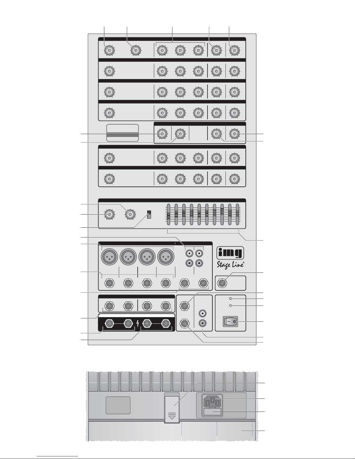
1.1 Frontplatte des Powermixers
1 Lautstärkeregler LEVEL jeweils für alle Mono-
Eingangskanäle 1– 4 und Stereo-Eingangskanäle 5/6 und 7/8
2 Regler TALKOVER SENS. (nur Kanal 1) zur Ein-
stellung des Grades der Pegelabsenkung bei der
TALKOVER-Funktion (⇒Kapitel 6.3)
3 Klangregelung jeweils für alle Eingangskanäle:
TREBLE für die Höhen (±12dB/10 kHz)
MID für die Mitten (±12 dB/1kHz)
BASS für die Tiefen (±12dB/100Hz)
4 Regler FX/AUX / MON jeweils für alle Eingangs-
kanäle; bestimmt den Pegel, mit dem das Kanalsignal auf den internen Effektprozessor und auf
ein an der Buchse FX/AUX SEND (10) angeschlossenes Effektgerät gegeben wird und damit
die Effektintensität für den Kanal; der eingestellte Pegel ist jeweils von der Einstellung des
Kanalpegels LEVEL (1) abhängig; in der MAINMONITOR-Betriebsart wird zudem hierüber der
Anteil des Kanals für das Monitorsignal eingestellt
5 PAN-Regler jeweils für die Mono-Eingangs-
kanäle 1– 4 oder BAL-Regler für die Stereo-Eingangskanäle 5/6 und 7/8; bestimmt die Position
des Kanalsignals im Stereopanorama des Summensignals bzw. die Lautstärkebalance zwischen dem rechten und linken Signal
6 PAN-Regler für den internen Echo-Effekt;
bestimmt die Position des Effektsignals im Stereopanorama
7 FX/AUX-Regler zur Einstellung der Gesamtlaut-
stärke des internen Effekts
8 Klangregelung für das Summensignal
9 Eingangsbuchse STEREO AUX RETURN zum
Einspeisen eines Effektsignals
10 Ausgangsbuchse FX/AUX SEND mit dem über
die Regler FX/AUX / MON (4) eingestellten Signal (Mono, asymmetrisch) zum Anschluss eines
Effektgeräts parallel zum internen Effekt
11 Anzeige PROTECT; leuchtet, wenn die Schutz-
schaltung aktiv ist (⇒ Kapitel 6.4)
12 Betriebsanzeige
13 Ein-/Ausschalter POWER
14 Ausgangsbuchsen TAPE REC (Cinch) zum An-
schluss einesAufnahmegerätes
15 6,3-mm-Klinkenbuchse für einen Fußschalter
zum Ein- und Ausschalten des internen EchoEffekts
16 6,3-mm-Klinkenbuchsen MAIN RIGHT/MONI-
TOR zum Anschluss der Lautsprecherbox für
den rechten Kanal des Summensignals im
MAIN-STEREO-Betrieb bzw. für das Monitorsignal im MAIN-MONITOR-Betrieb; die beiden
Buchsen sind parallel miteinander verbunden
17 6,3-mm-Klinkenbuchsen MAIN LEFT/MAIN zum
Anschluss der Lautsprecherbox für den linken
Kanal des Summensignals im MAIN-STEREOBetrieb bzw. für das Hauptsignal im MAINMONITOR-Betrieb; die beiden Buchsen sind
parallel miteinander verbunden
18 6,3-mm-Klinkenbuchsen MASTER INSERT zum
Einschleifen zusätzlicher Geräte zur Klangbearbeitung in den Summensignalweg (⇒ Kapitel5.2); die SEND-Buchsen können auch als
Summensignalausgang, z.B. zum Anschluss
eines weiteren Verstärkers, genutzt werden
19 6,3-mm-Stereo-Klinkenbuchsen für die Stereo-
Kanäle 5/6 und 7/8 zum Anschluss einer Stereosignalquelle mit Line-Pegel (z. B. Keyboard, CDSpieler, MD-Recorder)
20 Symmetrisch beschaltete Eingangsbuchsen
LINE (6,3-mm-Klinke) für die Mono-Eingangskanäle 1 –4 zum Anschluss von Signalen mit
Please unfold page 3. Then you can always see the
operating elements and connections described.
Contents
1 Operating Elements and Connections . . . 4
1.1 Front panel of the power mixer . . . . . . . . . . . 4
1.2 Rear panel of the power mixer . . . . . . . . . . . 5
2 Safety Notes . . . . . . . . . . . . . . . . . . . . . . . . . 5
3 Applications . . . . . . . . . . . . . . . . . . . . . . . . . 5
4 Setting up the System . . . . . . . . . . . . . . . . . 6
5 Connection . . . . . . . . . . . . . . . . . . . . . . . . . . 6
5.1 Inputs . . . . . . . . . . . . . . . . . . . . . . . . . . . . . . . 6
5.2 Effect ways . . . . . . . . . . . . . . . . . . . . . . . . . . 6
5.3 Outputs . . . . . . . . . . . . . . . . . . . . . . . . . . . . . 7
5.4 Foot switch . . . . . . . . . . . . . . . . . . . . . . . . . . 7
5.5 Power supply . . . . . . . . . . . . . . . . . . . . . . . . . 7
6 Operation . . . . . . . . . . . . . . . . . . . . . . . . . . . 7
6.1 Adding effects . . . . . . . . . . . . . . . . . . . . . . . . 7
6.2 Monitor signal . . . . . . . . . . . . . . . . . . . . . . . . 8
6.3 TALKOVER function . . . . . . . . . . . . . . . . . . . 8
6.4 Protective circuits . . . . . . . . . . . . . . . . . . . . . 8
7 Switching off and Transport . . . . . . . . . . . . 8
8 Specifications . . . . . . . . . . . . . . . . . . . . . . . 9
1 Operating Elements and Connections
1.1 Front panel of the power mixer
1 Volume control LEVEL, each for all mono input
channels 1 –4 and stereo input channels 5/ 6
and 7/8
2 Control TALKOVER SENS. (channel 1 only) to
adjust the degree of level attenuation when using
the TALKOVER function (⇒chapter 6.3).
3 Equalizer, each for all input channels:
TREBLE (±12 dB/10kHz)
MID (±12 dB/1kHz)
BASS (±12dB/100 Hz)
4 Control FX/AUX / MON, each for all input chan-
nels; to define the level at which the channel
signal is fed to the internal effect processor
and to an effect unit connected to the jack
FX/AUX/SEND (10) and thus to define the effect
intensity for the channel; the level adjusted respectively depends on the adjustment of the
channel level LEVEL (1); in the MAIN MONITOR
mode, this control is also used to adjust the part
of the channel for the monitor signal
5 PAN control, each for the mono input channels
1–4 or BAL controls for the stereo input channels 5/ 6 and 7/ 8; to define the position of the
channel signal in the stereo panorama of the
master signal or the volume balance between
the right signal and the left signal
6 PAN control for the internal echo effect; to define
the position of the effect signal in the stereo panorama
7 FX/AUX control to adjust the total volume of the
internal effect
8 Equalizer for the master signal
9 Input jack STEREO AUX RETURN to feed in an
effect signal
10 Output jack FX/AUX SEND with the signal
(mono, unbalanced) adjusted via the controls
FX/ AUX/ MON (4) to connect an effect unit in
parallel to the internal effect
11 LED PROTECT; will light up with the protective
circuit activated (⇒ chapter 6.4)
12 Power LED
13 POWER switch
14 Output jacks TAPE REC (phono jacks) to
connect a recorder
15 6.3mm jack for a foot switch to switch on and off
the internal echo effect
16 6.3 mm jacks MAIN RIGHT/MONITOR to con-
nect the speaker system for the right channel of
the master signal in the MAIN STEREO mode or
for the monitor signal in the MAIN MONITOR
mode; the two jacks are connected to each other
in parallel
17 6.3 mm jacks MAIN LEFT/ MAIN to connect the
speaker system for the left channel of the master
signal in the MAIN STEREO mode or for the
main signal in the MAIN MONITOR mode; the
two jacks are connected to each other in parallel
18 6.3 mm jacks MASTER INSERT to insert addi-
tional units for processing the sound in the
master signal way (⇒ chapter 5.2); the SEND
jacks can also be used as a master signal output,
e.g. to connect another amplifier
19 6.3 mm stereo jacks for the stereo channels 5 / 6
and 7/8 to connect a stereo signal source with line
level (e.g. keyboard, CD player, MD recorder)
20 Balanced input jacks LINE (6.3mm jacks) for the
mono input channels 1 –4 to connect signals
with line level (e.g. instrument amplifiers, effect
units)
21 Microphone input jacks MIC (XLR jacks) for the
mono input channels 1– 4
22 Input jacks (phono jacks) for the stereo channels
5/6 and 7/8 to connect a stereo signal source
with line level (e.g. CD player, MD recorder, DA T
4
GB
D
A
CH
Line-Pegel (z.B. Instrumentenverstärker, Effektgeräte)
21 Mikrofon-Eingangsbuchsen MIC (XLR) für die
Mono-Eingangskanäle 1– 4
22 Eingangsbuchsen (Cinch) für die Stereo-Kanäle
5/6 und 7/8 zum Anschluss einer Stereosignalquelle mit Line-Pegel (z.B. CD-Spieler, MDRecorder, DAT-Recorder) als alternative Anschlussmöglichkeit zu den Klinkenbuchsen (19)
23 Schalter MODE für die Wahl der Betriebsart:
MAIN STEREO
an den Lautsprecherausgängen (16, 17) liegt
das Stereo-Summensignal an
MAIN/ MONITOR
am Lautsprecherausgang MAIN LEFT/ MAIN
(17) liegt das Mono-Summensignal an, am
Ausgang MAIN RIGHT/MONITOR (16) das
über die Regler FX/AUX/MON (4) gemischte
Monitorsignal
24 Lautstärkeregler LEFT/MAIN für den linken
Kanal des Summensignals im MAIN-STEREOBetrieb bzw. das Hauptsignal im MAIN-MONITOR-Betrieb
25 Lautstärkeregler RIGHT/MONITOR für den
rechten Kanal des Summensignals im MAINSTEREO-Betrieb bzw. das Monitorsignal im
MAIN-MONITOR-Betrieb
26 REPEAT-Regler zur Einstellung der Anzahl der
Wiederholungen für den internen Echo-Effekt
27 DELAY-Regler zur Einstellung der Verzöge-
rungszeit für den internen Echo-Effekt
1.2 Rückseite des Powermixers
28 Verriegelung für die Staufachklappe (31)
29 Netzbuchse zum Anschluss an eine Steckdose
(230V~/50Hz) über das beiliegende Netzkabel
30 Halterung für die Netzsicherung;
eine durchgebrannte Sicherung nur durch eine
gleichen Typs ersetzen
31 Staufachklappe
2 Hinweise für den sicheren Gebrauch
Die Geräte des Verstärkersystems (Powermixer,
Lautsprecherboxen, Mikrofone) entsprechen allen
erforderlichen Richtlinien der EU und sind deshalb
mit gekennzeichnet.
Beachten Sie auch unbedingt die folgenden Punkte:
●
Das Verstärkersystem ist nur zur Verwendung im
Innenbereich geeignet. Schützen Sie alle Komponenten vor Tropf- und Spritzwasser, hoher Luftfeuchtigkeit und Hitze (zulässiger Einsatztemperaturbereich 0– 40°C).
●
Stellen Sie keine mit Flüssigkeit gefüllten Gefäße,
z.B. Trinkgläser, auf die Geräte.
●
Die im Powermixer entstehende Wärme muss
durch Luftzirkulation abgegeben werden. Decken
Sie darum die Lüftungsöffnungen nicht ab.
●
Nehmen Sie den Powermixer nicht in Betrieb oder
ziehen Sie sofort den Netzstecker aus der Steckdose, wenn:
1. sichtbare Schäden am Gerät oder an der Netzanschlussleitung vorhanden sind,
2. nach einem Sturz oder Ähnlichem der Verdacht
auf einen Defekt besteht,
3. Funktionsstörungen auftreten.
Lassen Sie das Gerät in jedem Fall in einer Fachwerkstatt reparieren.
●
Ziehen Sie den Netzstecker nie am Kabel aus der
Steckdose, fassen Sie immer am Stecker an.
●
Verwenden Sie für die Reinigung nur ein trockenes, weiches Tuch, niemals Wasser oder Chemikalien.
●
Werden die Komponenten des Systems zweckentfremdet, nicht richtig montiert oder angeschlossen, falsch bedient oder nicht fachgerecht
repariert, kann keine Haftung für daraus resultierende Sach- oder Personenschäden und keine
Garantie für die Geräte übernommen werden.
3 Einsatzmöglichkeiten
Das Verstärkersystem PMX-250SET besteht aus
einem Powermixer (Kombination aus Mischpult mit
integriertem Effekt und Stereoverstärker), zwei
Lautsprecherboxen und zwei dynamischen Mikrofonen sowie Lautsprecher- und Mikrofonkabeln. Der
Verstärker liefert eine Leistung von 2 × 200W
MAX
und verfügt über Schutzschaltungen gegen Kurzschluss und Überhitzung. Der Powermixer und die
beiden Lautsprecherboxen lassen sich zu einem rollbaren Transportkoffer montieren. Dadurch eignet
sich das System ideal für den mobilen Einsatz z.B.
Live-Auftritte kleiner Bands, Tanzveranstaltungen,
Vorführungen etc.
Soll das System endgültig aus dem Betrieb
genommen werden, übergeben Sie es zur
umweltgerechten Entsorgung einem örtlichen Recyclingbetrieb.
WARNUNG Der Powermixer wird mit lebensge-
fährlicher Netzspannung (230V~)
versorgt. Nehmen Sie deshalb niemals selbst Eingriffe am Gerät vor
und stecken Sie nichts durch die
Lüftungsöffnungen! Es besteht die
Gefahr eines elektrischen Schlages.
2 Safety Notes
The units of the amplifier system (power mixer,
speaker systems, microphones) correspond to all
required directives of the EU and are therefore
marked with .
Please observe the following items in any case:
●
The amplifier system is suitable for indoor use
only. Protect all components against dripping
water and splash water, high air humidity , and heat
(admissible ambient temperature range 0– 40 °C).
●
Do not place any vessel filled with liquid (e. g. a
drinking glass) on the units.
●
The heat generated in the power mixer must be
dissipated by air circulation. Therefore, do not
cover the air vents.
●
Do not operate the power mixer or immediately
disconnect the plug from the mains socket
1. in case of visible damage to the unit or to the
mains cable,
2. if a defect might have occurred after the unit
was dropped or suffered a similar accident,
3. if malfunctions occur.
In any case the unit must be repaired by skilled
personnel.
●
Never pull the mains cable for disconnecting the
mains plug from the socket, always seize the plug.
●
For cleaning only use a dry, soft cloth; never use
chemicals or water.
●
No guarantee claims for the units and no liability for
any resulting personal damage or material damage
will be accepted if the components of the system
are used for other purposes than originally intended, if they are not correctly mounted, connected or
operated, or not repaired in an expert way.
●
Important for U.K. Customers!
The wires in this mains lead are coloured in accordance with the following code:
green/yellow = earth
blue = neutral
brown = live
As the colours of the wires in the mains lead of this
appliance may not correspond with the coloured
markings identifying the terminals in your plug,
proceed as follows:
1. The wire which is coloured green and yellow
must be connected to the terminal in the plug
which is marked with the letter E or by the earth
symbol , or coloured green or green and yellow.
2. The wire which is coloured blue must be connected to the terminal which is marked with the
letter N or coloured black.
3. The wire which is coloured brown must be connected to the terminal which is marked with the
letter L or coloured red.
Warning
-
This appliance must be earthed.
3 Applications
The amplifier system PMX-250SET consists of a
power mixer (combination of a mixer with integrated
effect and a stereo amplifier), two speaker systems,
two dynamic microphones, and speaker and microphone cables. The amplifier supplies a power of 2 ×
200WMAX and is equipped with protective circuits
against short circuit and overheating. The power
mixer and the two speaker systems can be assembled to a transport case with castors. Thus, the
system is ideal for mobile applications, e.g. live performances of small bands, dances, presentations etc.
If the system is to be put out of operation
definitively, take it to a local recycling plant
for a disposal which is not harmful to the
environment.
WARNING The power mixer is supplied with
hazardous mains voltage (230V~).
Leave servicing to skilled personnel
only and never insert anything into
the air vents, otherwise you will risk
an electric shock!
recorder) as an alternative connection to the
6.3mm jacks (19)
23 Switch MODE to select the operating mode:
MAIN STEREO
At the speaker outputs (16, 17), the stereo
master signal is available.
MAIN/MONITOR
At the speaker output MAIN LEFT/MAIN (17),
the mono master signal is available; at the
output MAIN RIGHT/MONITOR (16), the
monitor signal mixed via the controls
FX/AUX/MON (4).
24 Volume control LEFT/MAIN for the left channel
of the master signal in the MAIN STEREO mode
or the main signal in the MAIN MONITOR mode
25 Volume control RIGHT/MONITOR for the right
channel of the master signal in the MAIN
STEREO mode or the monitor signal in the MAIN
MONITOR mode
26 REPEATcontrol to adjust the number of repeats
for the internal echo effect
27 DELAY control to adjust the delay time for the
internal echo effect
1.2 Rear panel of the power mixer
28 Lock for the storage compartment cover (31)
29 Mains jack for connection to a mains socket
(230V~/50Hz) via the mains cable supplied
30 Support for the mains fuse;
replace a burnt-out fuse by one of the same type
only
31 Storage compartment cover
5
GB
D
A
CH
5.2 Effektwege
Über die Buchsen FX/AUX SEND (10) und STEREO AUX RETURN (9) kann ein zusätzliches
Effektgerät mit Line-Pegel angeschlossen werden.
Dabei wird das Effektgerät parallel zu dem internen
Effekt betrieben, d.h. der Effektanteil wird für jeden
Kanal mit dem jeweiligen Regler FX/AUX/MON
gemeinsam für beide Effekte eingestellt.
1) Den Eingang des Effektgeräts mit der KlinkenBuchse FX/AUX SEND (Mono, asymmetrisch)
verbinden.
2) Den Ausgang des Effektgeräts mit der KlinkenBuchse STEREO AUX RETURN verbinden.
Besitzt das Effektgerät getrennte Ausgangsbuchsen für den linken und rechten Kanal, einen
geeigneten Adapter verwenden (z. B. MCA-202
von MONACOR). Hat das Gerät nur einen MonoAusgang, kann es über einen Adapter (z.B. NTA170 von MONACOR) angeschlossen werden, bei
dem die Kontakte von Spitze und Ring verbunden sind (beim Anschluss über einen Mono-Klinkenstecker würde der Effekt nur auf den linken
Kanal der Signalsumme gelangen).
Alternativ kann der Ausgang eines Effektgeräts auch über einen der Mono- oder StereoEingangskanäle angeschlossen werden (20 bzw.
19 oder 22). Dadurch sind zusätzlich Klangregelung und Panorama- bzw. Balance-Einstellungen
für das Effektsignal möglich. Der Regler
FX/AUX/MON dieses Kanals muss unbedingt
auf „0“ gedreht werden, da es sonst zur Rückkopplung kommen kann.
Um das Summensignal im Klang zu verändern, lässt
sich über die Buchsen MASTER INSERT (18) ein
zusätzliches Effektgerät einschleifen. Ein über die
Buchse STEREO AUX RETURN (9) eingespeister
Effekt wird dem Originalsignal hinzugemischt.
Dagegen wird, bei Verwendung der MASTER-
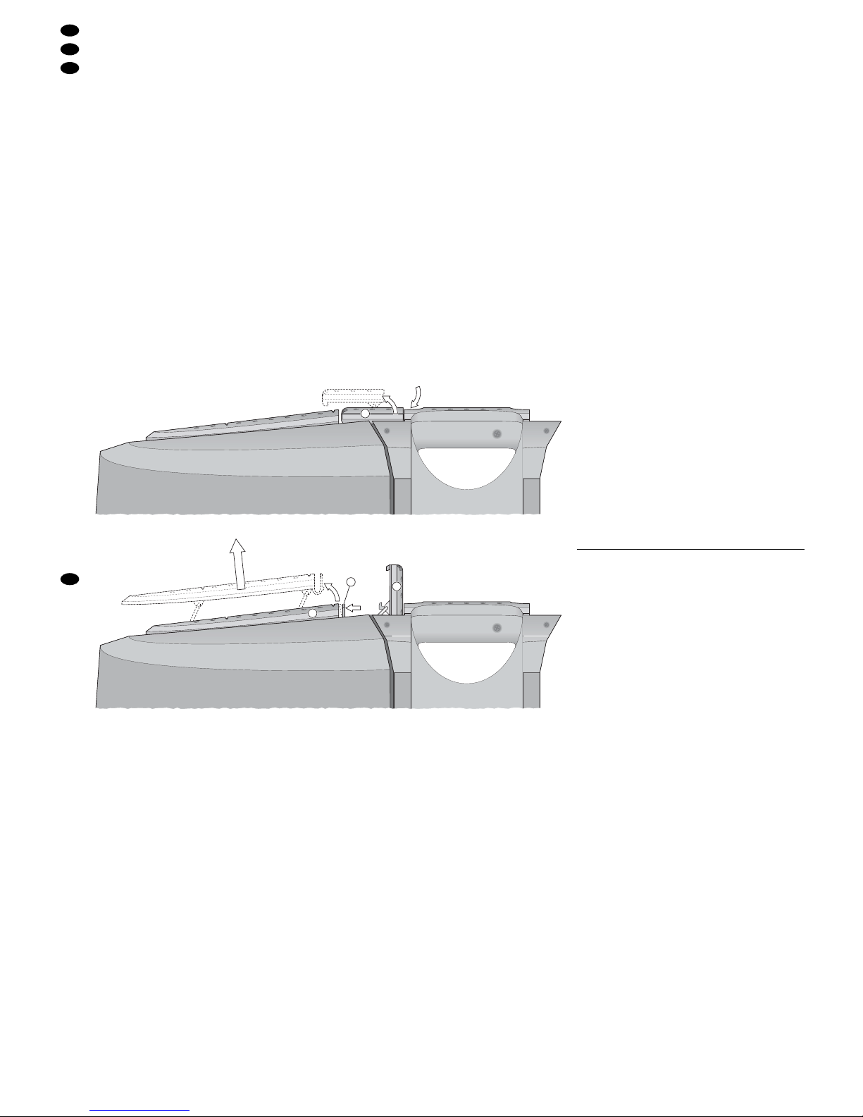
4Setting up the System
To remove the speaker systems, proceed according
to the figures 3 and 4:
1) Put your fingers into the recess next to the handle
of the power mixer, press to disengage the clip
(a) and fold it upwards.
2) To unlock the handle (b), bend the two catches
(c) towards the handle, then lift the handle
upwards.
3) Seize the speaker system by its handle (b) and
remove it from the base.
4) The microphones and the connection cables are
stored in the compartment. To open the storage
compartment cover (31), slide the lock (28)
upwards, then open the cover downwards.
Find a suitable place and either put the speaker
systems directly on their rubber feet or put them on
standard speaker stands (e. g. from the PAST-...
series from “img Stage Line”) via the recessed stand
sleeves. To prevent accidental displacement, two of
the castors on the base of the power mixer are provided with brakes.
5 Connection
Switch off the power mixer prior to connecting any
units or changing any existing connections.
5.1 Inputs
Each of the mono channels 1 – 4 is provided both
with an XLR microphone input and a 6.3mm jack for
signals with line level which can be used as an alternative to the microphone input. Both jacks are designed for balanced signals. However, it is also possible to connect sources with unbalanced signals.
For this purpose, the connection for the line inputs
can simply be made via 2-pole plugs; for the XLR
inputs, an adapter is required with the XLR contacts
1 and 3 bridged.
1) Connect microphones to the XLR jacks MIC (21).
2) Connect units with line mono output (e. g. instrument amplifiers, effect units) to the 6.3mm jacks
LINE (20).
3) Connect units with line stereo output (e. g. CD
player, MD recorder, DAT recorder) to the phono
jacks (22) or alternatively to the 6.3 mm stereo
jacks (19) of the stereo channels 5/6 and 7/8.
5.2 Effect ways
The jacks FX/AUX SEND (10) and STEREO AUX
RETURN (9) allow connection of an additional effect
unit with line level. The effect unit is operated in parallel to the internal effect, i.e. the effect part for each
channel is adjusted with the corresponding control
FX/AUX/MON for both effects together.
1) Connect the input of the effect unit to the 6.3 mm
jack FX/AUX SEND (mono, unbalanced).
2) Connect the output of the effect unit to the
6.3mm jack STEREO AUX RETURN. If the effect
unit has separate output jacks for the left channel
and the right channel, use a suitable adapter
(e.g. MONACOR MCA-202). If the unit only has
a mono output, it may be connected via an adapter (e.g. MONACOR NTA-170) with the contacts
of tip and ring connected (in case of connection
via a 6.3 mm mono plug, the effect would only
arrive at the left channel of the master signal).
As an alternative, connect the output of an
effect unit via one of the mono or stereo input
channels (20, 19, or 22). This will allow to make
additional sound adjustments and panorama
or balance adjustments for the effect signal.
To prevent feedback, always set the control
FX/AUX/MON of this channel to “0”.
To modify the sound of the master signal, an additional effect unit can be inserted via the jacks
MASTER INSERT (18). An effect fed in via the jack
STEREO AUX RETURN (9) will be added to the
original signal, whereas, when using the MASTER
INSERT jacks, the entire signal will be fed through
the effect unit connected.
3) Connect the SEND jacks (18) to the inputs of the
effect unit (e. g. equalizer, compressor). In the
MAIN STEREO mode, these jacks will supply a
stereo signal; in the MAIN MONITOR mode, the
mono master signal is available at the SEND
LEFT jack, the FX/AUX SEND signal at the
SEND RIGHT jack.
The signals are dependent on the adjustment
of the MASTER volume (24, 25), but independent
of the master equalizer (8).
4) Connect the outputs of the effect unit to the
RETURN jacks (unbalanced). As soon as the
jacks are connected, the internal signal way from
the mixer to the power amplifier is interrupted
and, instead of the master signal, the signal fed in
here is fed to the power amplifier via the master
equalizer (8).
6
GB
D
A
CH
4 Aufstellen des Systems
Zum Abnehmen der Lautsprecherboxen den Abbildungen 3 und 4 entsprechend vorgehen:
1) Neben dem Griff des Powermixers in die Vertiefung greifen, die Lasche (a) entriegeln und nach
oben klappen.
2) Zum Ausrasten des Griffs (b) die beiden Rastnasen (c) in Richtung Griff biegen und dann den
Griff nach oben schwenken.
3) Die Lautsprecherbox am Griff (b) anfassen und
aus dem Sockel heben.
4) Die Mikrofone und die Anschlusskabel befinden
sich im Staufach. Zum Öffnen der Staufachklappe (31) die Verriegelung (28) nach oben
schieben und dann die Klappe nach unten aufschwenken.
Die Lautsprecherboxen an geeigneter Stelle entweder direkt auf die Kunststofffüße oder über die eingelassenen Stativhülsen auf übliche Lautsprecherstative (z. B. aus der PAST-Serie von „img Stage
Line”) stellen. Gegen versehentliches Wegrollen
können zwei der Rollen am Sockel des Powermixers festgestellt werden.
5 Anschluss
Vor dem Anschließen von Geräten bzw. Ändern bestehender Anschlüsse den Powermixer ausschalten.
5.1 Eingänge
Jeder der Monokanäle 1 –4 besitzt sowohl einen
XLR-Mikrofoneingang als auch eine Klinkenbuchse
für Signale mit Line-Pegel, die alternativ zum Mikrofoneingang genutzt werden kann. Beide Buchsen
sind für symmetrische Signale beschaltet. Es können aber auch Quellen mit asymmetrischen Signalen angeschlossen werden. Dafür kann der
Anschluss bei den Line-Eingängen einfach über 2polige Klinkenstecker erfolgen; bei den XLR-Eingängen ist ein Adapter erforderlich, bei dem die
XLR-Kontakte 1 und 3 gebrückt sind.
1) Mikrofone an die XLR-Buchsen MIC (21) anschließen.
2) Geräte mit Line-Mono-Ausgang (z. B. Instrumentenverstärker, Effektgeräte) an die 6,3-mm-Klinkenbuchsen LINE (20) anschließen.
3) Geräte mit Line-Stereo-Ausgang (z. B. CD-Spieler, MD-Recorder, DAT-Recorder) an die CinchBuchsen (22) oder alternativ an die 6,3-mm-Stereo-Klinkenbuchsen (19) der Stereokanäle 5/ 6
oder 7/8 anschließen.
1.
a
2.
3.
a
b
c
➂
➃

INSERT-Buchsen, das gesamte Signal durch das
angeschlossene Effektgerät geführt.
3) Die SEND-Buchsen (18) mit den Eingängen des
Effektgerätes (z. B. Equalizer, Kompressor) verbinden. Im MAIN-STEREO-Betrieb liefern diese
Buchsen ein Stereosignal, im MAIN-MONITORBetrieb liegt an der SEND-LEFT-Buchse das
Mono-Summensignal, an der SEND-RIGHTBuchse das FX/AUX-SEND-Signal.
Die Signale sind von der Einstellung der
Gesamtlautstärke MASTER (24, 25) abhängig,
jedoch von der Gesamtklangeinstellung (8)
unabhängig.
4) Die Ausgänge des Effektgerätes mit den
RETURN-Buchsen (asymmetrisch beschaltet)
verbinden. Sobald die Buchsen belegt sind, ist
der interne Signalweg vom Mischpult zum Endverstärker unterbrochen und statt des Summensignals wird das hier eingespeiste Signal über die
Gesamtklangeinstellung (8) zur Endstufe geführt.
5.3 Ausgänge
1) Mit den beiliegenden oder anderen geeigneten
Lautsprecherkabeln (z.B. MSC-1000 von „img
Stage Line“) je einen Ausgang SPEAKER OUTPUT – linker Kanal MAIN LEFT (17), rechter
Kanal MAIN RIGHT (18) – mit einer Lautsprecherbox (Buchse auf der Vorderseite) verbinden.
Wichtig:
●
Bei einer Parallelschaltung mehrerer Lautsprecher darf die Mindestimpedanz von 4Ω an
jedem Lautsprecherausgang des Verstärkers
nicht unterschritten werden.
●
Auf keinen Fall Instrumentenkabel für den
Anschluss von Lautsprechern verwenden.
Diese haben in der Regel einen zu geringen
Querschnitt, was zu Leistungsverlusten und
zur Kabelerwärmung führen kann.
2) Am Ausgang TAPE REC (14) steht ein von der
Gesamtklangeinstellung (8) und der Einstellung
der Gesamtlautstärke MASTER (24, 25) unabhängiges Summensignal zur Verfügung. Das
Signal ist auch im MAIN-MONITOR-Betrieb stereofon. Hier kann ein Aufnahmegerät oder weiteres Gerät mit Line-Eingang angeschlossen werden, z.B. ein zusätzlicher Verstärker.
3) Werden die SEND-Buchsen (18) nicht für das Einschleifen eines Effektes genutzt, kann hier auch
das Summensignal des Powermixers abgenommen werden, um es z. B. auf einen zusätzlichen
Verstärker zu leiten. (⇒ Kapitel 5.2, Punkt 3)
5.4 Fußschalter
Wenn gewünscht, zum Ein- und Ausschalten des
internen Echo-Effektes einen Fußschalter mit einem
2-poligen 6,3-mm-Klinkenstecker (z. B. FS-100 von
„img Stage Line“) an die Buchse FOOT SWITCH
(15) anschließen.
5.5 Stromversorgung
Das Netzkabel mit der Netzbuchse (29) verbinden.
Anschließend den Stecker des Kabels in eine Steckdose (230V~/50Hz) stecken.
6 Bedienung
Den Powermixer mit dem Netzschalter (13) einschalten. Die Betriebsanzeige ON (12) leuchtet.
Mit dem Schalter MODE (23) die gewünschte
Betriebsart wählen:
MAIN STEREO für eine Hauptbeschallung in Stereo
ohne separaten Monitorlautsprecher
MAIN/ MONITOR für eine Hauptbeschallung in
Mono mit zusätzlichem Kontrolllautsprecher
(Monitor) auf der Bühne
Die folgenden Bedienschritte dienen nur als Hilfestellung, es sind auch andere Vorgehensweisen möglich.
1) Zur Grundeinstellung vorerst die LEVEL-Regler
(1), Effektregler FX/AUX/MON (4) und die Klangregler (3) aller Eingangskanäle, den Regler TALKOVER SENS (2), den Gesamteffektregler FX/
AUX (7) sowie die Klangregler (8) für das Summensignal auf „0“ stellen. Die PAN-Regler (5) bzw .
BAL-Regler aller Eingangskanäle auf „C“ stellen.
2) Mit den Reglern LEFT/ MAIN (24) und RIGHT/
MONITOR (25) [im MAIN-MONITOR-Betrieb nur
mit dem Regler LEFT/MAIN] wird die Gesamtlautstärke eingestellt.
Die Regler etwa zur Hälfte aufdrehen, so dass
die nachfolgenden Einstellungen über die angeschlossenen Lautsprecher zu hören sind.
3) Mit den Lautstärkereglern LEVEL (1) die Signale
der Eingangskanäle mischen oder nach Bedarf
ein- und ausblenden. Die Regler der nicht benutzten Kanäle stets auf „0“ stellen. Beim Einsatz
der mitgelieferten Mikrofone diese mit ihren
Schiebeschaltern einschalten.
4) Für jeden Eingangskanal getrennt den Klang mit
den Klangreglern (3) – TREBLE für die Höhen,
MID für die Mitten, BASS für die Tiefen – optimal
einstellen.
5) Mit den PAN-Reglern (5) die Position des jeweiligen Mono-Eingangssignals im Stereopanorama
des Summensignals bestimmen. Bei Linksanschlag gelangt das Signal nur auf den linken, bei
Rechtsanschlag nur auf den rechten Ausgang. In
der Mittelposition bekommen beide Ausgänge
den gleichen Anteil (Mono).
Bei den Stereokanälen entsprechend mit dem
BAL-Regler die Balance zwischen dem linken
und rechten Signal einstellen.
6) Mit dem Equalizer (8) den Klang für die Signalsumme wie gewünscht einstellen.
5.3 Outputs
1) With the speaker cables supplied or other suitable speaker cables (e.g. MSCN-1000 from “img
Stage Line”), connect one SPEAKER OUTPUT
each – MAIN LEFT (17), MAIN RIGHT(18) – to a
speaker system (jack on the front panel).
Important:
●
In case of parallel connection of several speakers, the minimum impedance at each speaker
output of the amplifier must not fall below 4 Ω.
●
Never use instrument cables for connecting
speakers. Usually these cables have a cross
section which is too small which may result in
power loss and heating of the cables.
2) At the output TAPE REC (14), a master signal is
available which is independent of the master
equalizer (8) and of the MASTER volume (24,
25). The signal is stereophonic, also in the MAIN
MONITOR mode. This output allows connection
of a recorder or of another unit with line input,
e.g. an additional amplifier.
3) If the SEND jacks (18) are not used for inserting
an effect, the master signal of the power mixer
can also be picked up here, e.g. to feed it to an
additional amplifier. (⇒ chapter 5.2, item 3)
5.4 Foot switch
If desired, connect a foot switch with a 2-pole
6.3mm plug (e. g. FS-100 from “img Stage Line”) to
the jack FOOT SWITCH (15) for switching on and off
the internal echo effect.
5.5 Power supply
Connect the mains cable to the mains jack (29).
Then connect the plug of the cable to a mains socket
(230V~/50Hz).
6 Operation
Switch on the power mixer with the POWER switch
(13). The LED ON (12) will light up.
With the switch MODE (23), select the desired
operating mode:
MAIN STEREO for a main PAsound in stereo with-
out a separate monitor speaker
MAIN/MONITOR for a main PA sound in mono with
an additional monitor speaker on stage
The following operating steps only serve as an aid;
you may also proceed differently.
1) As a basic adjustment for the time being, set
the LEVEL controls (1), the effect controls
FX/AUX/MON (4) and the equalizer controls (3)
of all input channels, the control TALKOVER
SENS (2), the total effect control FX/AUX (7), and
the equalizer controls (8) for the master signal to
“0”. Set the PAN controls (5) or BALcontrols of all
input channels to “C”.
2) With the controls LEFT/ MAIN (24) and RIGHT/
MONITOR (25) [in the MAIN MONITOR mode
only with the control LEFT/MAIN], the master
volume is adjusted.
Advance the controls to approximately midposition so that the subsequent adjustments will
be audible via the speakers connected.
3) With the volume controls LEVEL (1), mix the signals of the input channels or fade them in and out
as required. Always set the controls of the channels which are not used to “0”. When using the
microphones supplied, switch them on with their
sliding switches.
4) Adjust the optimum sound for each input channel
separately with the equalizer controls (3) –
TREBLE for the high frequencies, MID for the
midrange frequencies, BASS for the low frequencies.
5) With the PAN controls (5), define the position of
the respective mono input signal in the stereo
panorama of the master signal. With the control
at the left stop, the signal will only be fed to the
left output; with the control at the right stop, it will
only be fed to the right output. In mid-position,
both outputs will receive the same part (mono).
For the stereo channels, adjust the balance
between the left signal and the right signal with
the BAL control accordingly.
6) With the equalizer (8), adjust the sound for the
master signal as desired.
7) With the controls LEFT/ MAIN (24) and RIGHT/
MONITOR (25) [in the MAIN MONITOR mode
only with the control LEFT/MAIN], adjust the final
level of the audio system, then readjust the
sound, if required.
6.1 Adding effects
An echo effect created via the integrated effect processor can be added to the signal of each input
channel. The signal of an effect unit connected to
the jacks FX/AUX SEND (10) and STEREO AUX
RETURN (9) is added in parallel.
1) With the controls FX /AUX/ MON (4), adjust the
signal part for each channel which is to be fed to
the internal effect processor and to an external
effect unit. The further the control is advanced,
the more powerful is the effect for the channel.
The effect level is also dependent on the channel
volume adjusted with the control LEVEL (1). If no
effect is desired for a channel, set its control
FX/AUX/MON to “0”.
In case of overload of the input of an effect unit
connected, turn back the controls accordingly.
CAUTION Never adjust the audio system to a
very high volume. Permanent high
volumes may damage your hearing!
The human ear will get accustomed
to high volumes which do not seem
to be that high after some time.
Therefore, do not further increase a
high volume after getting used to it.
7
GB
D
A
CH
 Loading...