

IMG STAGE LINE PMX-202 Instruction Manual
4-KANAL-STEREO-MISCHVERSTÄRKER
4-CHANNEL STEREO MIXING AMPLIFIER
AMPLIFICATEUR-MIXEUR STÉRÉRO, 4 CANAUX
AMPLIFICATORE MIXER STEREO A 4 CANALI
PMX-202 Best.-Nr. 20.2120
BEDIENUNGSANLEITUNG • INSTRUCTION MANUAL • MODE D’EMPLOI
ISTRUZIONI PER L’USO • GEBRUIKSAANWIJZING • MANUAL DE INSTRUCCIONES • INSTRUKCJA OBSŁUGI
SIKKERHEDSOPLYSNINGER • SÄKERHETSFÖRESKRIFTER • TURVALLISUUDESTA

2
wwwwww..iimmggssttaaggeelliinnee..ccoomm
Bevor Sie einschalten …
Wir wünschen Ihnen viel Spaß mit Ihrem neuen Gerät
von „img Stage Line”. Bitte lesen Sie diese Bedienungsanleitung vor dem Betrieb gründlich durch. Nur so lernen
Sie alle Funktionsmöglichkeiten kennen, vermeiden
Fehlbedienungen und schützen sich und Ihr Gerät vor
eventuellen Schäden durch unsachgemäßen Gebrauch.
Heben Sie die Anleitung für ein späteres Nachlesen auf.
Der deutsche Text beginnt auf der Seite 4.
Before switching on …
We wish you much pleasure with your new “img Stage
Line” unit. Please read these operating instructions
carefully prior to operating the unit. Thus, you will get to
know all functions of the unit, operating errors will be prevented, and yourself and the unit will be protected
against any damage caused by improper use. Please
keep the operating instructions for later use.
The English text starts on page 4.
D
A
CH
GB
Avant toute installation …
Nous vous souhaitons beaucoup de plaisir à utiliser cet
appareil “img Stage Line”. Lisez ce mode d'emploi entièrement avant toute utilisation. Uniquement ainsi, vous
pourrez apprendre l’ensemble des possibilités de fonctionnement de l’appareil, éviter toute manipulation erronée
et vous protéger, ainsi que l’appareil, de dommages éventuels engendrés par une utilisation inadaptée. Conservez
la notice pour pouvoir vous y reporter ultérieurement.
La version française se trouve page 8.
Prima di accendere …
Vi auguriamo buon divertimento con il vostro nuovo apparecchio di “img Stage Line”. Leggete attentamente le
istruzioni prima di mettere in funzione l'apparecchio. Solo
così potete conoscere tutte le funzionalità, evitare
comandi sbagliati e proteggere voi stessi e l'apparecchio
da eventuali danni in seguito ad un uso improprio. Conservate le istruzioni per poterle consultare anche in futuro.
Il testo italiano inizia a pagina 8.
F
B
CH
I
Antes de la utilización …
Le deseamos una buena utilización para su nuevo aparato “img Stage Line”. Por favor, lea estas instrucciones
de uso atentamente antes de hacer funcionar el aparato.
De esta manera conocerá todas las funciones de la
unidad, se prevendrán errores de operación, usted y el
aparato estarán protegidos en contra de todo daño
causado por un uso inadecuado. Por favor, guarde las
instrucciones para una futura utilización.
El texto en español empieza en la página 12.
E
PL
Przed Uruchomieniem …
Życzymy zadowolenia z nowego produktu “img Stage
Line”. Dzięki tej instrukcji obsługi będą państwo w
stanie poznać wszystkie funkcje tego urządzenia. Stosując się do instrukcji unikną państwo błędów i ewentualnego uszkodzenia urządzenia na skutek nieprawidłowego użytkowania. Prosimy zachować instrukcję.
Tekst polski zaczyna się na stronie 16.
Før du tænder …
God fornøjelse med dit nye “img Stage Line” produkt.
Læs venligst sikkerhedsanvisningen nøje, før du tager
produktet i brug. Dette hjælper dig med at beskytte produktet mod ukorrekt ibrugtagning. Gem venligst denne
betjeningsvejledning til senere brug.
Du finder sikkerhedsanvisningen på side 18.
DK
FIN
Innan du slår på enheten
Vi önskar dig mycket glädje med din nya “img Stage
Line” produkt. Läs igenom säkerhetsföreskrifterna noga
innan enheten tas i bruk. Detta kan förhindra att problem
eller fara för dig eller enheten uppstår vid användning.
Spara instruktionerna för framtida användning.
Säkerhetsföreskrifterna återfinns på sidan 18.
Ennen kytkemistä …
Toivomme Sinulle paljon miellyttäviä hetkiä uuden “img
Stage Line” laitteen kanssa. Ennen laitteen käyttöä
pyydämme Sinua huolellisesti tutustumaan turvallisuusohjeisiin. Näin vältyt vahingoilta, joita virheellinen
laitteen käyttö saattaa aiheuttaa. Ole hyvä ja säilytä käyttöohjeet myöhempää tarvetta varten.
Turvallisuusohjeet löytyvät sivulta 18.
S
Voor u inschakelt …
Wij wensen u veel plezier met uw nieuwe apparaat van
“img Stage Line”. Lees deze gebruikershandleiding
grondig door, alvorens het apparaat in gebruik te nemen.
Alleen zo leert u alle functies kennen, vermijdt u foutieve
bediening en behoedt u zichzelf en het apparaat voor
eventuele schade door ondeskundig gebruik. Bewaar de
handleiding voor latere raadpleging.
De Nederlandstalige tekst vindt u op pagina 12.
NL
B
3
LEVEL
010
EFF
010
TREBLE
–5
+5
BAL
LR
BASS
–5
+5
MIC
LINE
L
R (MONO)
LEVEL
010
EFF
010
TREBLE
–5
+5
PAN
LR
BASS
–5
+5
PHANTOM
MIC 1+2
LINE
LEVEL
010
EFF
010
TREBLE
–5
+5
PAN
LR
BASS
–5
+5
LEVEL
010
EFF
010
TREBLE
–5
+5
BAL
LR
BASS
–5
+5
LRPLAY
TAPE REC.
DELAY
010
FEEDBACK
010
EFF LEVEL
010
010
010010
L MASTER OUTPUT R
SUB OUTEXT. EFF SEND
L AUX/EXT. EFF RETURN R
12
LR
RX RX/
OPTION
MICMIC
LINE
LINE
L
R
(MONO)
L MASTER LEVEL R
INT. EFF
ON/
OFF
CLIP CLIP
3-4 5-6
6-CHANNEL
MIXING AMPLIFIER
PMX-202
POWER ON
GREEN
PROTECT
RED
1234567
➀
13 14 15 16 17 18 19 20 21 22 23
8
9
10
11
12
24 25 26 27 28
➁
POWER
ON
OFF
FREQUENCY
863.05 MHz
Use only with a 250 V fuse
Employer uniquement avec
un fusible de 250 V
LEFT
(4Ω min.)
600W
MAX
POWER
RIGHT
(4Ω min.)
SPEAKON
CONNECTION
2+ 1+
2
-
1
-
+
-

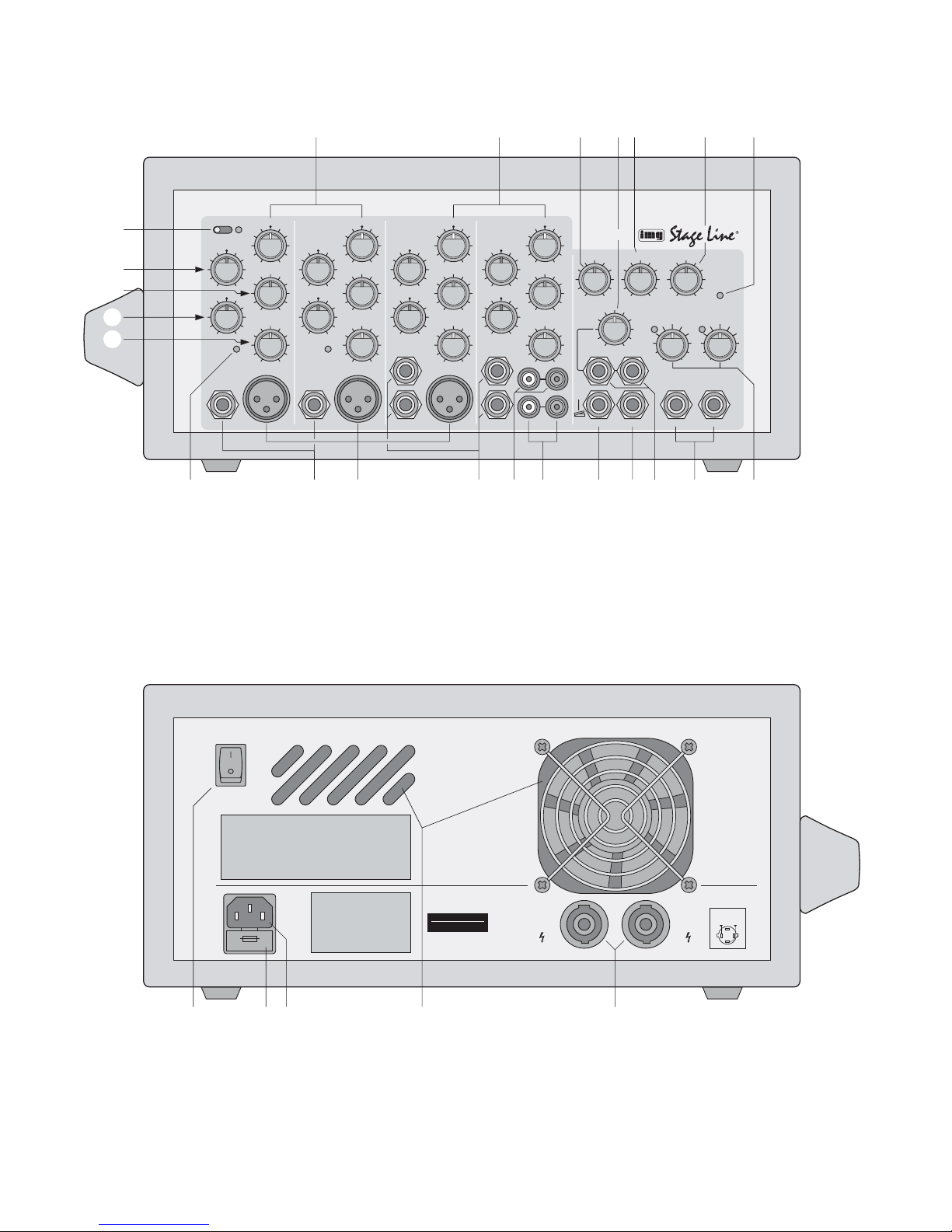
Please unfold page 3. Then you can always see
the operating elements and connections described.
1 Operating Elements and Connections
1.1 Front panel
1 Panorama controls PAN for placing the mono
channel signal in the stereo base
2 Balance controls BAL; if only the jack R (MONO)
[16] is connected, it operates as a panorama
control
3 Control DELAYfor adjusting the delay time of the
echoes
4 Level control for the input jacks AUX/ EXT. EFF
RETURN (21) below the control
5 Control FEEDBACK for adjusting the number of
echoes
6 Control EFF LEVEL for the intensity of the inter-
nal echo effect
7 Indicating LED
green = operating indication, unit operates nor-
mally
red = protective circuit is activated:
1. for approx. 5 seconds after switching-on
(switch-on delay)
2. if a short circuit has occurred at a speaker output (28)
3 if the unit is overheated
8 Switch PHANTOM (with red indicating LED) for
central connection of the 12 V phantom power
supply for the XLR jacks MIC (15) of the channels 1 and 2;
required for connecting capacitor or electret
microphones operating at a 12V phantom power
9 Control TREBLE (±12 dB/10 kHz) for the input
channels 1, 2, 3-4, and 5-6
10 Effect Send control EFF for the input channels 1,
2, 3-4, and 5-6:
for adjusting the level at which the corresponding
channel signal is mixed to the internal echo circuit and the output EXT. EFF SEND (19)
11 Control BASS (± 12dB/30Hz) for the input chan-
nels 1, 2, 3-4, and 5-6
12 Control LEVEL for the input channels 1, 2, 3-4,
and 5-6
13 LED RX; lights up when a signal from a wireless
microphone is received
14 6.3 mm jacks LINE (unbal.) for connecting mono
units with line output (musical instrument, cassette recorder, etc.)
15 XLR jacks MIC (bal.) for connecting micro-
phones
16 6.3 mm jacks LINE (unbal.) for connecting stereo
units with line output (musical instrument, CD
player, etc.)
Note: For mono units, only connect the jack R
(MONO). Then the signal will internally be fed to
the right and left channels.
17 Phono jacks PLAY for reproducing a recorder or
for connecting another unit with line output
18 Phono jacks TAPE REC. for feeding the master
signal to a recorder
The output level is independent of the controls
MASTER LEVEL (23).
19 6.3 mm jacks EXT . EFF SEND either for connect-
ing the input of an effect unit or for connecting a
foot switch for switching on or off the internal
echo effect
20 6.3 mm jack SUB OUT for connecting a sub-
woofer (see chapter 4.8)
The output level depends on the controls
MASTER LEVEL (23).
21 6.3 mm jacks AUX/ EXT. EFF RETURN (unbal.)
as a further input for a unit with line output or, in
connection with the jack EXT. EFF SEND (19),
for inserting an effect unit
22 6.3 mm jacks MASTER OUTPUT:
at these jacks, the master signal is available
which may e.g. be fed to a second amplifier for
additional PAapplication
The output level is independent of the controls
MASTER LEVEL (23).
23 Controls MASTER LEVEL for the volume of the
speakers connected
1.2 Rear panel
24 POWER switch
25 Support for the mains fuse;
always replace a burnt-out fuse by one of the
same type
26 Mains jack for connecting the unit to a mains
socket (230V~/50Hz) via the supplied cable
27 Ventilation slots; do not cover to prevent over-
heating inside the unit!
28 SPEAKON
®
jacks for connection of speaker
systems
Caution! Do not connect any microphones with
unbalanced output to the channels 1 and 2 if
the microphone phantom power is switched on:
The red LED next to the switch PHANTOM (8)
lights up. These microphones may be damaged.
Caution! With applied phantom power no
microphones with unbalanced output must be
connected to the microphone inputs of channels 1 and 2, as these microphones may be
damaged.
4
GB
D
A
CH
Bitte klappen Sie die Seite 3 heraus. Sie sehen
dann immer die beschriebenen Bedienelemente
und Anschlüsse.
1 Übersicht der Bedienelemente und
Anschlüsse
1.1 Frontseite
1 Panoramaregler PAN zum Platzieren des Mono-
Kanalsignals in der Stereo-Basis
2 Balanceregler BAL; ist nur die Buchse R (MONO)
[16] angeschlossen, arbeitet er als Panoramaregler
3 Regler DELAY zum Einstellen der Verzöge-
rungszeit der Echos
4 Pegelregler für die Eingangsbuchsen AUX/EXT.
EFF RETURN (21) unterhalb des Reglers
5 Regler FEEDBACK zum Einstellen der Anzahl
der Echos
6 Regler EFF LEVEL für die Intensität des internen
Echoeffekts
7 Kontrollanzeige
grün = Betriebsanzeige, Gerät arbeitet normal
rot = Schutzschaltung ist aktiviert:
1. ca. 5 Sekunden lang nach dem Einschalten
(Einschaltverzögerung)
2. wenn an einem Lautsprecherausgang (28) ein
Kurzschluss aufgetreten ist
3. wenn das Gerät überhitzt ist
8 Schalter PHANTOM (mit roter Kontroll-LED)
zum zentralen Zuschalten der 12-V-Phantomspeisung für die XLR-Buchsen MIC (15) der
Kanäle 1 und 2;
erforderlich beim Anschluss von Kondensatoroder Elektretmikrofonen, die mit 12-V-Phantomspeisung arbeiten
9 Höhenregler TREBLE (±12dB/10 kHz) für die
Eingangskanäle 1, 2, 3-4 und 5-6
10 Effekt-Send-Regler EFF für die Eingangskanäle
1, 2, 3-4 und 5-6:
zum Einstellen des Pegels, mit dem das jeweilige
Kanalsignal auf die interne Echoschaltung und
den Ausgang EXT. EFF SEND (19) gemischt wird
11 Tiefenregler BASS (±12 dB/ 30Hz) für die Ein-
gangskanäle 1, 2, 3-4 und 5-6
12 Pegelregler LEVEL für die Eingangskanäle 1, 2,
3-4 und 5-6
13 Anzeige RX; leuchtet, wenn ein Signal von
einem Funkmikrofon empfangen wird
14 6,3-mm-Klinkenbuchsen LINE (asym.) für den
Anschluss von Mono-Geräten mit Line-Ausgang
(Musikinstrument, Kassettenrecorder etc.)
15 XLR-Buchsen MIC (sym.) für den Anschluss von
Mikrofonen
16 6,3-mm-Klinkenbuchsen LINE (asym.) für den
Anschluss von Stereo-Geräten mit Line-Ausgang (Musikinstrument, CD-Spieler etc.)
Hinweis: Bei Mono-Geräten nur die Buchse
R (MONO) anschließen. Das Signal wird dann
intern auf den rechten und linken Kanal gegeben.
17 Cinch-Buchsen PLAY für die Wiedergabe eines
Aufnahmegerätes oder zum Anschluss eines
anderen Gerätes mit Line-Ausgang
18 Cinch-Buchsen TAPE REC., um das Summen-
signal auf ein Aufnahmegerät zu geben
Der Ausgangspegel ist von den Reglern MASTER LEVEL (23) unabhängig.
19 6,3-mm-Klinkenbuchsen EXT. EFF SEND ent-
weder zum Anschluss an den Eingang eines
Effektgerätes oder zum Anschluss eines Fußschalters, über den sich der interne Echoeffekt
ein- und ausschalten lässt
20 6,3-mm-Klinkenbuchse SUB OUT zum Anschluss
eines Subwoofers (siehe Kap. 4.8)
Der Ausgangspegel ist von den Reglern MASTER LEVEL (23) abhängig.
21 6,3-mm-Klinkenbuchsen AUX/EXT. EFF RE-
TURN (asym.) als weiterer Eingang für ein Gerät
mit Line-Ausgang oder in Verbindung mit der
Buchse EXT. EFF SEND (19) zum Einschleifen
eines Effektgerätes
22 6,3-mm-Klinkenbuchsen MASTER OUTPUT:
hier liegt das Summensignal an, das z. B. auf
einen zweiten Verstärker zur zusätzlichen Beschallung gegeben werden kann
Der Ausgangspegel ist von den Reglern MASTER LEVEL (23) unabhängig.
23 Regler MASTER LEVEL für die Lautstärke der
angeschlossenen Lautsprecher
1.2 Rückseite
24 Ein-/Ausschalter POWER
25 Halterung für die Netzsicherung;
eine durchgebrannte Sicherung nur durch eine
gleichen Typs ersetzen
26 Netzbuchse zum Anschluss an eine Steckdose
(230V~/50Hz) über das beiliegende Verbindungskabel
27 Lüftungsöffnungen; nicht abdecken, damit es im
Gerät nicht zu einer Überhitzung kommt!
28 SPEAKON
®
-Buchsen zum Anschluss von Laut-
sprecherboxen
Vorsicht! Keine Mikrofone mit asymmetrischem Ausgang an die Kanäle 1 und 2 anschließen, wenn die Mikrofon-Phantomspeisung eingeschaltet ist: Es leuchtet die rote LED
neben dem Schalter PHANTOM (8). Diese
Mikrofone können beschädigt werden.
und 2 keine Mikrofone mit asymmetrischem
Ausgang angeschlossen sein, da diese beschädigt werden können.
Vorsicht! Bei anliegender Phantomspannung
dürfen an den Mikrofoneingängen der Kanäle 1
2 Hinweise für den sicheren Gebrauch
Der Verstärker entspricht der Richtlinie für elektromagnetische Verträglichkeit 89/ 336/ EWG und der
Niederspannungsrichtlinie 73/23/EWG.
Beachten Sie auch unbedingt die folgenden Punkte:
●
Verwenden Sie das Gerät nur im Innenbereich.
Schützen Sie es vor Tropf- und Spritzwasser,
hoher Luftfeuchtigkeit und Hitze (zulässiger Einsatztemperaturbereich 0– 40°C).
●
Stellen Sie keine mit Flüssigkeit gefüllten Gefäße,
z.B. Trinkgläser, auf das Gerät.
●
Die im Gerät entstehende Wärme muss durch
Luftzirkulation abgegeben werden. Decken Sie
die Lüftungsöffnungen (27) nicht ab.
●
Nehmen Sie das Gerät nicht in Betrieb und ziehen
Sie sofort den Netzstecker aus der Steckdose,
wenn:
1. sichtbare Schäden am Gerät oder an der Netzanschlussleitung vorhanden sind,
2. nach einem Sturz oder Ähnlichem der Verdacht
auf einen Defekt besteht,
3. Funktionsstörungen auftreten.
Geben Sie das Gerät in jedem Fall zur Reparatur
in eine Fachwerkstatt.
●
Ziehen Sie den Netzstecker nie an der Zuleitung
aus der Steckdose, fassen Sie immer am Stecker
an!
●
Verwenden Sie zum Reinigen nur ein trockenes
weiches Tuch, niemals Chemikalien oder Wasser.
●
Wird das Gerät zweckentfremdet, nicht richtig
angeschlossen, falsch bedient oder nicht fachgerecht repariert, kann keine Garantie für das Gerät
und keine Haftung für daraus resultierende Sachoder Personenschäden übernommen werden.
3 Einsatzmöglichkeiten und Zubehör
Der Verstärker ist speziell zur Beschallung bei Veranstaltungen, Vorträgen etc. konzipiert. Er ist mit vier
Eingangskanälen und einem Empfangsteil für ein
Funkmikrofon (Übertragungsfrequenz 863,05MHz)
ausgestattet. Die Eingangskanäle lassen sich folgendermaßen nutzen:
Kanal 1 (mono)
für ein Funkmikrofon oder
für ein kabelgebundenes Mikrofon oder
für ein Audiogerät mit Line-Ausgang (z.B. Musikinstrument, Kassettenrecorder)
Kanal 2 (mono)
für ein kabelgebundenes Mikrofon oder
für ein Audiogerät mit Line-Ausgang
Kanal 3-4 (stereo)
für ein kabelgebundenes Mikrofon oder
für ein Audiogerät mit Line-Ausgang (z. B. CDSpieler, Kassettenrecorder)
Kanal 5-6 (stereo)
für ein Audiogerät mit Line-Ausgang
Aus dem Sortiment von „img Stage Line“ können
z.B. folgende Funkmikrofone mit dem PMX-202 verwendet werden:
3.1 Zulassung
Die Zulassung für das Gerät ist nach der R + T TERichtlinie (Radio and Telecommunication Technical
Equipment) in den Staaten der Europäischen Union
gültig. Die Zulassungsnummer ist in den technischen Daten angegeben. Für den Betrieb in Staaten
außerhalb der EU fragen Sie bitte Ihren Fachhändler oder die MONACOR-Niederlassung des entsprechenden Landes.
In der Bundesrepublik Deutschland ist die Frequenz 863,05 MHz für den Betrieb von drahtlosen
Audio-Übertragungssystemen freigegeben. Da diese
Frequenz in anderen Ländern der EU für diesen Anwendungszweck möglicherweise nicht zur Verfügung
steht, informieren Sie sich vor dem Betrieb des Gerätes außerhalb Deutschlands bitte bei Ihrem Fachhändler oder bei der entsprechenden Behörde des
Landes.
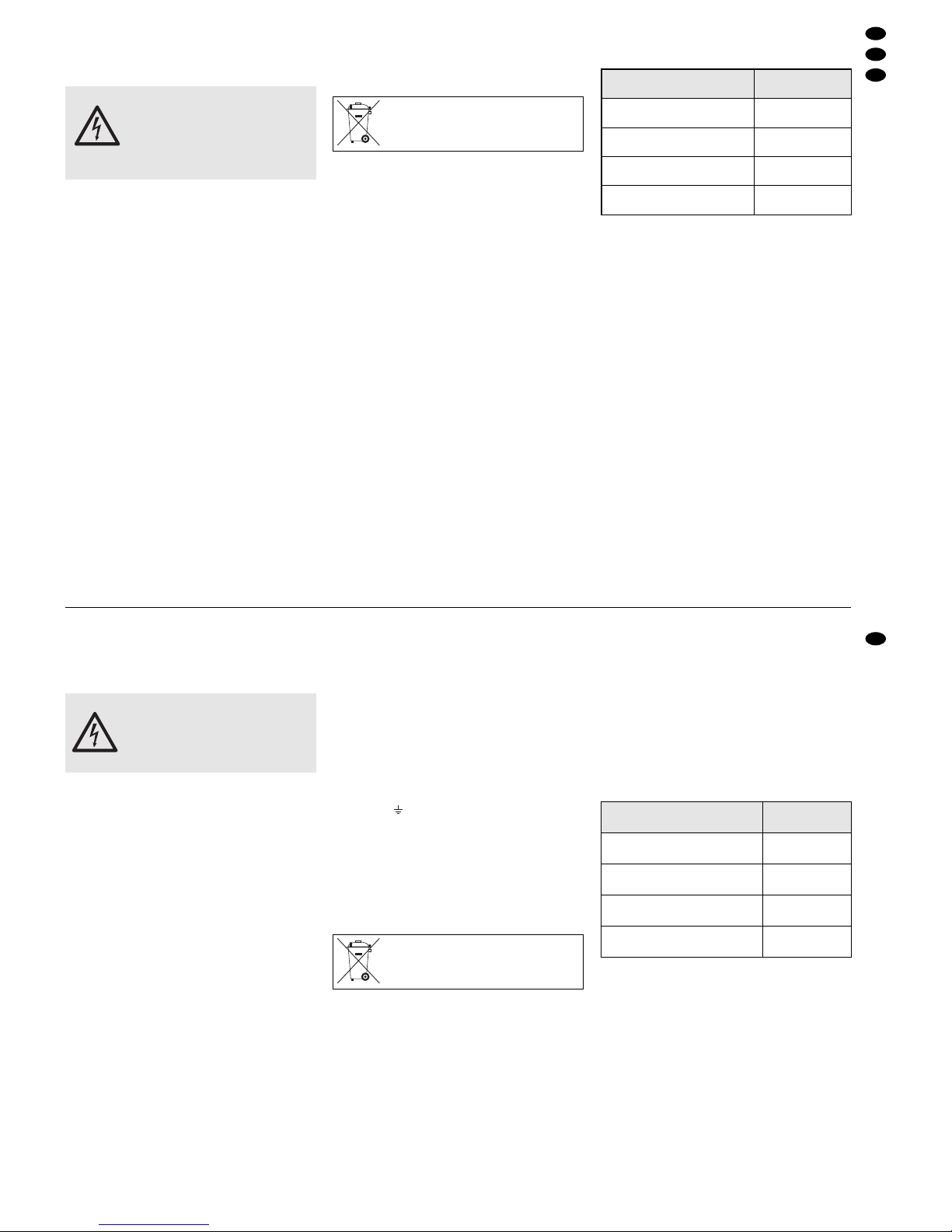
Soll das Gerät endgültig aus dem Betrieb genommen werden, übergeben Sie
es zur umweltgerechten Entsorgung
einem örtlichen Recyclingbetrieb.
WARNUNG Das Gerät wird mit lebensgefährlicher
Netzspannung (230V~) versorgt.
Nehmen Sie deshalb niemals selbst
Eingriffe am Gerät vor und stecken
Sie nichts durch die Lüftungsöffnungen! Es besteht die Gefahr
eines elektrischen Schlages.
2 Safety Notes
The amplifier corresponds to the directive for electromagnetic compatibility 89/ 336/EEC and to the
low voltage directive 73/23/EEC.
Please observe the following items in any case:
●
The unit is suitable for indoor use only. Protect it
against dripping water and splash water, high air
humidity, and heat (admissible ambient temperature range 0– 40°C).
●
Do not place any vessel filled with liquid on the
unit, e.g. a drinking glass.
●
The heat being generated within the unit must be
carried off by air circulation. Do not cover the air
vents (27).
●
Do not operate the unit and immediately disconnect the plug from the mains socket
1. if there is visible damage to the unit or to the
mains cable,
2. if a defect might have occurred after the unit
was dropped or suffered a similar accident,
3. if malfunctions occur.
In any case the unit must be repaired by skilled
personnel.
●
Never pull the mains cable for disconnecting the
mains plug from the socket, always seize the plug.
●
For cleaning only use a dry, soft cloth; never use
chemicals or water.
●
No guarantee claims for the unit and no liability for
any resulting personal damage or material damage will be accepted if the unit is used for other
purposes than originally intended, if it is not correctly connected, operated, or not repaired in an
expert way.
●
Important for U.K. Customers!
The wires in the mains lead are coloured in accordance with the following code:
green/yellow = earth
blue = neutral
brown = live
As the colours of the wires in the mains lead of this
appliance may not correspond with the coloured
markings identifying the terminals in your plug,
proceed as follows:
1. The wire which is coloured green and yellow
must be connected to the terminal in the plug
which is marked with the letter E or by the earth
symbol , or coloured green or green and yel-
low.
2. The wire which is coloured blue must be connected to the terminal which is marked with the
letter N or coloured black.
3. The wire which is coloured brown must be connected to the terminal which is marked with the
letter L or coloured red.
Warning – This appliance must be earthed.
3 Applications and Accessories
The amplifier is especially designed for PAapplications at events, lectures, etc. It is equipped with four
input channels and a receiver part for a wireless
microphone (transmission frequency 863.05 MHz).
The input channels can be used as follows:
channel 1 (mono)
for a wireless microphone or
for a cable-connected microphone or
for an audio unit with line output (e. g. musical
instrument, cassette recorder)
channel 2 (mono)
for a cable-connected microphone or
for an audio unit with line output
channel 3-4 (stereo)
for a cable-connected microphone or
for an audio unit with line output (e.g. CD player,
cassette recorder)
channel 5-6 (stereo)
for an audio unit with line output
The following wireless microphones from the “img
Stage Line” product range can e.g. be used with the
PMX-202:
3.1 Approval
According to the R+TTE directive (Radio and Telecommunication Technical Equipment), the approval
for the unit is valid in the countries of the European
Union. The approval number can be found in the
specifications. For operation in countries outside the
EU, please contact your retailer or the MONACOR
subsidiary in the particular country.
In the Federal Republic of Germany, the frequency 863.05MHz has been approved for the operation of wireless audio transmission systems. As
this frequency may not be available for this field of
application in other countries of the EU, please
contact your retailer or the corresponding authorities
of the particular country if the system is operated
outside the Federal Republic of Germany.
If the unit is to be put out of operation
definitively, take it to a local recycling
plant for a disposal which is not harmful
to the environment.
WARNING The unit is supplied with hazardous
mains voltage (230 V~). Never make
any modification on the unit and do not
insert anything through the air vents!
Otherwise this may cause an electric
shock hazard.
5
GB
D
A
CH
Typ
Bezeichnung
Bestell-Nr.
Handmikrofon mit
integriertem Sender
TXS-820HT
24.0900
Taschensender für ein
Kopfbügelmikro z.B. HSE-110
TXS-820HSE
24.0880
Taschensender mit
Krawattenmikrofon
TXS-820LT
24.0920
Taschensender mit
Kopfbügelmikrofon
TXS-820SX
24.0940
Type
Designation
Order No.
Hand-held microphone with
integrated transmitter
TXS-820HT
24.0900
Pocket transmitter for a headband
microphone, e.g. HSE-110
TXS-820HSE
24.0880
Pocket transmitter with
tie-clip microphone
TXS-820LT
24.0920
Pocket transmitter with
headband microphone
TXS-820SX
24.0940

4 Anschlüsse herstellen
Vor dem Anschließen von Geräten bzw. Ändern bestehender Anschlüsse den Verstärker ausschalten.
Beim Anschluss der Klinkenbuchsen LINE (14, 16)
werden die XLR- (15) oder Cinch-Buchsen (17)
nicht abgeschaltet. Darum darf an jedem Kanal
immer nur ein Signal zur Zeit anliegen.
4.1 Mikrofone
Wird ein Funkmikrofon verwendet, ist der Kanal 1
hiermit belegt. Zusätzlich können zwei kabelgebundene Mikrofone an die XLR-Buchsen MIC (15) der
Kanäle 2 und 3-4 angeschlossen werden. Wird kein
Funkmikrofon eingesetzt, lässt sich auch an den
Kanal 1 ein kabelgebundenes Mikrofon anschließen.
Phantomgespeiste Mikrofone (12V) können über
die Kanäle 1 und 2 betrieben werden.
4.2 Audiogeräte
Bis zu fünf Audiogeräte mit Line-Ausgang, z.B.
Musikinstrument, CD-Spieler, Kassettenrecorder , lassen sich an die 6,3-mm-Klinkenbuchsen anschließen:
Stereo-Geräte an die Buchsen (16) der Kanäle
3-4 und 5-6 anschließen. Sind die Buchsen AUX/
EXT. EFF RETURN (21) nicht mit einem Effektgerät
belegt, kann auch hier ein Stereo-Gerät angeschlossen werden, wenn keine Klangregelung erforderlich
ist. Werden die Cinch-Buchsen PLAY (17) nicht für
ein Aufnahmegerät benötigt, lässt sich hier ein Audiogerät alternativ zu den Klinkenbuchsen anschließen.
Zum Anschluss von Mono-Geräten die Buchsen
(14) der Kanäle 1 und 2 verwenden sowie jeweils
die untere Buchse R (MONO) [16] der Kanäle 3-4
und 5-6.
4.3 Aufnahmegerät
1) Für Tonaufnahmen den Eingang eines Aufnahmegerätes an die Cinch-Buchsen TAPE REC.
(18) anschließen. Hier liegt das Summensignal
unabhängig von den Reglern MASTER LEVEL
(23) an.
2) Zum Abhören der Aufnahme den Ausgang des
Aufnahmegerätes an die Cinch-Buchsen PLAY
(17) anschließen. Beim Abhören der Aufnahme
darf jedoch kein Signal an den Buchsen LINE
(16) des Kanals 5-6 anliegen (ggf. das Gerät an
diesen Buchsen ausschalten).
4.4 Effektgerät
Um ein Effektgerät in den Summensignalweg einzuschleifen, den Eingang des Effektgerätes an die
Buchse EXT. EFF SEND (19) anschließen und den
Ausgang an die Buchsen AUX / EXT. EFF RETURN
(21).
4.5 Fußschalter
Um den internen Echoeffekt ein- und auszuschalten, lässt sich an die Buchse EXT. EFF SEND (19)
alternativ zu einem Effektgerät ein Fußschalter anschließen (z.B. FS-60A von MONACOR).
4.6 Verstärker
Wird ein weiterer Verstärker zur Beschallung benötigt, diesen an die Buchsen MASTER OUTPUT
(22) anschließen. Hier liegt das Summensignal unabhängig von den Reglern MASTER LEVEL(23) an.
4.7 Lautsprecherboxen
An die SPEAKON®-Buchsen (28) auf der Geräterückseite die Lautsprecher anschließen. Die SPEAKON
®
Stecker in die entsprechenden Buchsen stecken und
nach rechts drehen, bis sie einrasten. Zum späteren
Herausziehen den Sicherungsriegel am Stecker
nach hinten schieben und den Stecker nach links
drehen.
4.8 Subwoofer
Bei Bedarf können die angeschlossenen Lautsprecherboxen im Tiefbassbereich durch einen Subwoofer unterstützt werden. An der Buchse SUB
OUT (20) liegt das Tiefbasssignal an, dessen Pegel
gemeinsam mit dem Pegel für die angeschlossenen
Hauptlautsprecher über die Regler MASTER LEVEL
(23) eingestellt wird. An diese Buchse einen AktivSubwoofer anschließen oder über einen Verstärker
einen passiven Subwoofer.
4.9 Stromversorgung
Nachdem alle Geräte angeschlossen sind, das beiliegende Netzkabel zuerst in die Netzbuchse (26) und
dann in eine Steckdose (230V~/50Hz) stecken.
5 Bedienung
1) Vor dem Einschalten die Regler MASTER VOLUME (23) auf „0“ drehen, um Einschaltgeräusche
zu vermeiden. Zur Grundeinstellung alle Regler
LEVEL (12), EFF (10) sowie den Regler EFF
LEVEL (6) und AUX / EXT. EFF RETURN (4) auf
„0“ drehen. Alle Regler P AN (1), BAL(2), TREBLE
(9) und BASS (11) in die Mittelstellung drehen.
2) Sind an den Kanälen 1 und 2 phantomgespeiste
Mikrofone angeschlossen, den Schalter PHANTOM (8) nach rechts schieben. Wenn nicht, den
Schalter nach links schieben.
3) Mit dem Schalter POWER (24) das Gerät einschalten. Die Kontrollanzeige (7) leuchtet für ca.
5Sekunden rot. In dieser Zeit sind die Lautsprecherausgänge (28) stumm geschaltet (Einschaltverzögerung). Anschließend leuchtet die Anzeige
grün.
Wird ein Funkmikrofon verwendet, dieses einschalten. Die rote Anzeige RX (13) leuchtet. Wenn
nicht, die Batterie des Mikrofons überprüfen oder
den Abstand zwischen Verstärker und Mikrofon
verringern. Die Reichweite beträgt ca. 30m.
Vorsicht! Bei eingeschalteter Phantomspeisung (die rote LED neben dem Schalter PHANTOM leuchtet nach dem Einschalten des Verstärkers) dürfen an den Mikrofoneingängen der
Kanäle 1 und 2 keine Mikrofone mit asymmetrischem Ausgang angeschlossen sein, da diese beschädigt werden können.
4 Connecting
Switch off the amplifier before connecting any units
or changing any existing connections. When connecting the jacks LINE (14, 16), the XLR jacks (15)
or phono jacks (17) are not switched off. Therefore,
only apply one signal to each channel at a time.
4.1 Microphones
When using a wireless microphone, the channel 1 is
reserved with this microphone. In addition, two
cable-connected microphones can be connected to
the XLR jacks MIC (15) of the channels 2 and 3-4. If
no wireless microphone is used, a cable-connected
microphone can also be connected to channel 1.
Phantom-powered microphones (12V) can be operated via the channels 1 and 2.
4.2 Audio units
The 6.3 mm jacks allow connection of up to five
audio units with line output, e.g. musical instrument,
CD player, cassette recorder:
Connect stereo units to the jacks (16) of the chan-
nels 3-4 and 5-6. If the jacks AUX/ EXT. EFF RETURN (21) are not reserved with an effect unit, it is
possible to connect a stereo unit here unless a tone
control is required. If the phono jacks PLAY (17) are
not required for a recorder, an audio unit can be
connected here as an alternative to the 6.3mm jacks.
For connecting mono units, use the jacks (14) of
the channels 1 and 2 and the corresponding lower
jack R (MONO) [16] of the channels 3-4 and 5-6.
4.3 Recorder
1) For audio recordings, connect the input of a recorder to the phono jacks TAPE REC. (18). At
these jacks, the master signal is available, independent of the controls MASTER LEVEL (23).
2) For monitoring the recording, connect the output of
the recorder to the phono jacks PLAY (17). While
monitoring the recording, however, no signal must
be applied to the jacks LINE (16) of the channel
5-6 (switch off the unit at these jacks, if required).
4.4 Effect unit
For inserting an effect unit into the master signal
way, connect the input of the effect unit to the jack
EXT. EFF SEND (19) and the output to the jacks
AUX/EXT. EFF RETURN (21).
4.5 Foot switch
For switching on or off the internal echo effect, a foot
switch (e.g. MONACOR FS-60A) may be connected
to the jack EXT. EFF SEND (19) as an alternative to
an effect unit.
4.6 Amplifier
If another amplifier for PAapplication is required, connect this amplifier to the jacks MASTER OUTPUT
(22). At these jacks, the master signal is available,
independent of the controls MASTER LEVEL (23).
4.7 Speaker systems
Connect the speakers to the SPEAKON®jacks (28)
on the rear side of the unit. Connect the SPEAKON
®
plugs to the corresponding jacks and turn them
clockwise until they lock into place. For later removal, push the locking latch on the plug to the rear
and turn the plug counter-clockwise.
4.8 Subwoofer
If required, the connected speaker systems can be
supported in the low bass range by a subwoofer.
The low bass signal is available at the jack SUB
OUT (20). Together with the level for the main
speakers connected, its level is adjusted via the
controls MASTER LEVEL (23). At this jack, connect
an active subwoofer or a passive subwoofer via an
amplifier.
4.9 Power supply
After all units have been connected, first connect the
supplied mains cable to the mains jack (26) and then
to a mains socket (230V~/50 Hz).
5 Operation
1) Prior to switching on, set the controls MASTER
VOLUME (23) to “0” to prevent switching noise.
For basic adjustment, set all controls LEVEL(12),
EFF (10) and the controls EFF LEVEL (6) and
AUX/ EXT. EFF RETURN (4) to “0”. Set all controls PAN (1), BAL (2), TREBLE (9), and BASS
(11) to mid-position.
2) If phantom-powered microphones are connected
to the channels 1 and 2, set the switch PHANTOM
(8) to the right. If not, set the switch to the left.
3) With the switch POWER (24) switch on the unit.
The indicating LED (7) shows red for approx.
5seconds. During this time the speaker outputs
(28) are muted (switch-on delay). Then the LED
shows green.
If a wireless microphone is used, switch it on.
The red LED RX (13) lights up. If it fails to light
up, check the battery of the microphone or
reduce the distance between the amplifier and
the microphone. The range is approx. 30m.
4) Switch on all units connected and slightly open
the controls MASTER LEVEL (23) so that the
subsequent adjustments will be reproduced via
the speakers connected.
5) Use the controls LEVEL (12) to mix the signals of
the units connected or to fade them in or out as
desired. Always set the controls of the channels
which are not used to “0”.
6) Use the controls PAN (1) to place the mono channel signals in the stereo base. In the stereo channels, adjust the balance with the controls BAL(2).
7) Adjust the volume for the speakers connected
with the controls MASTER LEVEL(23). When the
Caution! With the phantom power switched on
(the red LED next to the switch PHANTOM
lights up after switching on the amplifier), no
microphones with unbalanced output must be
connected to the microphone inputs of channels
1 and 2, as these microphones may be
damaged.
6
GB
D
A
CH
 Loading...