

IMG STAGE LINE PMX-150R Instruction Manual

BEDIENUNGSANLEITUNG • INSTRUCTION MANUAL • MODE D’EMPLOI
ISTRUZIONI PER L’USO • GEBRUIKSAANWIJZING • HANDLEIDING
CONSEJOS DE SEGURIDAD • SIKKERHEDSOPLYSNINGER • SÄKERHETSFÖRESKRIFTER • TURVALLISUUDESTA
PMX-150R Best.-Nr. 20.1600
POWER MIXER
TABLE DE MIXAGE AMPLIFIÉE
MIXER DI POTENZA

2
wwwwww..iimmggssttaaggeelliinnee..ccoomm
Bevor Sie einschalten ...
Wir wünschen Ihnen viel Spaß mit Ihrem neuen Gerät
von „img Stage Line“. Dabei soll Ihnen diese Bedienungsanleitung helfen, alle Funktionsmöglichkeiten
kennenzulernen. Die Beachtung der Anleitung vermeidet
außerdem Fehlbedienungen und schützt Sie und Ihr
Gerät vor eventuellen Schäden durch unsachgemäßen
Gebrauch.
Den deutschen Text finden Sie auf den Seiten 4– 9.
Before you switch on ...
We wish you much pleasure with your new unit by “img
Stage Line”. With these operating instructions you will be
able to get to know all functions of the unit. By following
these instructions false operations will be avoided, and
possible damage to you and your unit due to improper
use will be prevented.
You will find the English text on the pages 4–9.
D
A
CH
GB
Avant toute mise en service ...
Nous vous remercions d’avoir choisi un appareil “img
Stage Line” et vous souhaitons beaucoup de plaisir à
l’utiliser. Cette notice a pour objectif de vous aider à
mieux connaître les multiples facettes de l’appareil et à
vous éviter toute mauvaise manipulation.
La version française se trouve pages 10– 15.
Prima di accendere ...
Vi auguriamo buon divertimento con il Vostro nuovo apparecchio “img Stage Line”. Le istruzioni per l’uso Vi possono aiutare a conoscere tutte le possibili funzioni. E
rispettando quanto spiegato nelle istruzioni, evitate di
commettere degli errori, e così proteggete Voi stessi, ma
anche l’apparecchio, da eventuali rischi per uso improprio.
Il testo italiano lo potete trovare alle pagine 10– 15.
F
B
CH
I
Voordat u inschakelt ...
Wij wensen u veel plezier met uw nieuw toestel van “img
Stage Line”. Met behulp van bijgaande gebruiksaanwijzing zal u alle functiemogelijkheden leren kennen.
Door deze instructies op te volgen zal een slechte werking vermeden worden, en zal een eventueel letsel aan
uzelf en schade aan uw toestel tengevolge van onzorgvuldig gebruik worden voorkomen.
U vindt de nederlandstalige tekst op de pagina’s 16– 18.
Antes de cualquier instalación ...
Tenemos de agradecerle el haber adquirido un equipo
de “img Stage Line” y le deseamos un agrable uso. Por
favor lee las instrucciones de seguridad antes del uso.
La observación de las instrucciones de seguridad evita
operaciones erróneas y protege Vd. y vuestro aparato
contra todo daño posible por cualquier uso inadecuado.
Las instrucciones de seguridad se encuentran en la
página 19.
NL
B
E
Inden De tænder for apparatet ...
Vi ønsker Dem god fornøjelse med Deres nye “img Stage
Line” apparat. Læs oplysningerne for en sikker brug af apparatet før ibrugtagning. Følg sikkerhedsoplysningerne for
at undgå forkert betjening og for at beskytte Dem og
Deres apparat mod skade på grund af forkert brug.
Sikkerhedsoplysningerne finder De på side 19.
Förskrift
Vi önskar dig mycket nöje med din nya enhet från “img
Stage Line”. Läs gärna säkerhetsinstruktionerna innan
du använder enheten. Genom att följa säkerhetsinstruktionerna kan många problem undvikas, vilket annars kan
skada enheten.
Du finner säkerhetsinstruktionerna på sidan 20.
DK
S
Ennen virran kytkemistä…
T oivomme, että uusi “img Stage Line”-laitteesi tuo sinulle
paljon iloa ja hyötyä. Ole hyvä ja lue käyttöohjeet ennen
laitteen käyttöönottoa. Luettuasi käyttöohjeet voit käyttää laitetta turvallisesti ja vältyt laitteen väärinkäytöltä.
Käyttöohjeet löydät sivulta 20.
FIN
3
➁
➀
1 2 3 4 5 6 7
FOOT SW
OUT
+12
6
0
6
-12
+12
6
0
6
-12
EFFECT RTN AUX IN TAPE IN MONITOR MAIN
MASTER
EQUALIZER
ON
EFFECT OUT
REVERB
LOW
MON
125
250
500 1K
2K 4K
8K
5
10
0
5
10
0
5
10
0
5
10
0
5
10
0
5
10
0
PAD
-20dB
MIC
LINE
PAD
-20dB
MIC
LINE
PAD
-20dB
MIC
LINE
PAD
-20dB
MIC
LINE
PAD
-20dB
MIC
LINE
PAD
-20dB
MIC
LINE
PAD
-20dB
MIC
LINE
LEVEL
5
10
0
LEVEL
5
10
0
LEVEL
5
10
0
LEVEL
5
10
0
LEVEL
5
10
0
LEVEL
5
10
0
LEVEL
5
10
0
LEVEL
5
10
0
EFF
5
10
0
5
10
0
MON
EFF
5
10
0
5
10
0
MON
EFF
5
10
0
5
10
0
MON
EFF
5
10
0
5
10
0
MON
EFF
5
10
0
5
10
0
MON
EFF
5
10
0
5
10
0
MON
EFF
5
10
0
5
10
0
0
-15
+15
LOW
0
-15
+15
LOW
0
-15
+15
LOW
0
-15
+15
LOW
0
-15
+15
LOW
0
-15
+15
LOW
0
-15
+15
HIGH
0
-15
+15
HIGH
0
-15
+15
HIGH
0
-15
+15
HIGH
0
-15
+15
HIGH
0
-15
+15
HIGH
0
-15
+15
HIGH
0
-15
+15
EFFECT LOOP
AUX
RETURN
SEND
MONITOR
MAIN
OUTPUT
INPUT
PMX-150R
POWERED
MIXER
TAPE REC
L
R
L
R
CLIP
+6
+3
0dB
-5
-10
POWER
RED: PROTECT
GREEN: POWER
PHANTOM
POWERONOFF
9101112 131415 1617 1819 20
8
7
6
5
4
3
2
1
23
PMX-150R
POWERED MIXER
OUTPUT
(PARALLEL)
MAX. POWER
150W / MIN. 4 Ω
B
A
230V~/ 50Hz
POWER
30 31 32 33
24
25
26
27
28
29
4Ω – 150WRMS
8Ω – 104WRMS
+
-
8Ω – 75WRMS
+
-
8Ω – 75WRMS
+
-
+
-
4Ω – 38WRMS
8Ω – 26WRMS
+
-
4Ω – 38WRMS
8Ω – 26WRMS
+
-
4Ω – 38WRMS
8Ω – 26WRMS
+
-
4Ω – 38WRMS
8Ω – 26WRMS
OUTPUT
(PARALLEL)
OUTPUT
(PARALLEL)
OUTPUT
(PARALLEL)
➃
➂
➄
21
22

Bitte klappen Sie die Seite 3 heraus. Sie sehen
dann immer die beschriebenen Bedienelemente
und Anschlüsse.
Inhalt
1 Übersicht der Bedienelemente und
Anschlüsse . . . . . . . . . . . . . . . . . . . . . . . . . 4
1.1 Frontseite . . . . . . . . . . . . . . . . . . . . . . . . . . . 4
1.2 Rückseite . . . . . . . . . . . . . . . . . . . . . . . . . . . 5
2 Hinweise für den sicheren Gebrauch . . . . 5
3 Einsatzmöglichkeiten . . . . . . . . . . . . . . . . . 5
4 Geräte anschließen . . . . . . . . . . . . . . . . . . 6
4.1 Mikrofone . . . . . . . . . . . . . . . . . . . . . . . . . . . 6
4.2 Instrumente und Geräte mit Line-Ausgang . . 6
4.3 Lautsprecher . . . . . . . . . . . . . . . . . . . . . . . . . 6
4.4 Aufnahmegerät . . . . . . . . . . . . . . . . . . . . . . . 6
4.5 Effektgerät . . . . . . . . . . . . . . . . . . . . . . . . . . 6
4.6 Endverstärker für den Monitorweg . . . . . . . . 6
4.7 Endverstärker für die Signalsumme . . . . . . . 7
4.8 Zusatzgerät mit Line-Ausgang . . . . . . . . . . . 7
4.9 Fußschalter . . . . . . . . . . . . . . . . . . . . . . . . . . 7
4.10 Stromversorgung . . . . . . . . . . . . . . . . . . . . . 7
5 Bedienung . . . . . . . . . . . . . . . . . . . . . . . . . . 7
5.1 Mischen der Tonquellen . . . . . . . . . . . . . . . . 7
5.2 Monitorweg . . . . . . . . . . . . . . . . . . . . . . . . . . 7
5.3 Zumischen des internen Halls . . . . . . . . . . . 8
5.4 Externes Effektgerät verwenden . . . . . . . . . . 8
5.5 Aufnahmegerät und Zusatzgerät . . . . . . . . . 8
6 Technische Daten . . . . . . . . . . . . . . . . . . . . 9
Blockschaltbild . . . . . . . . . . . . . . . . . . . . . . 21
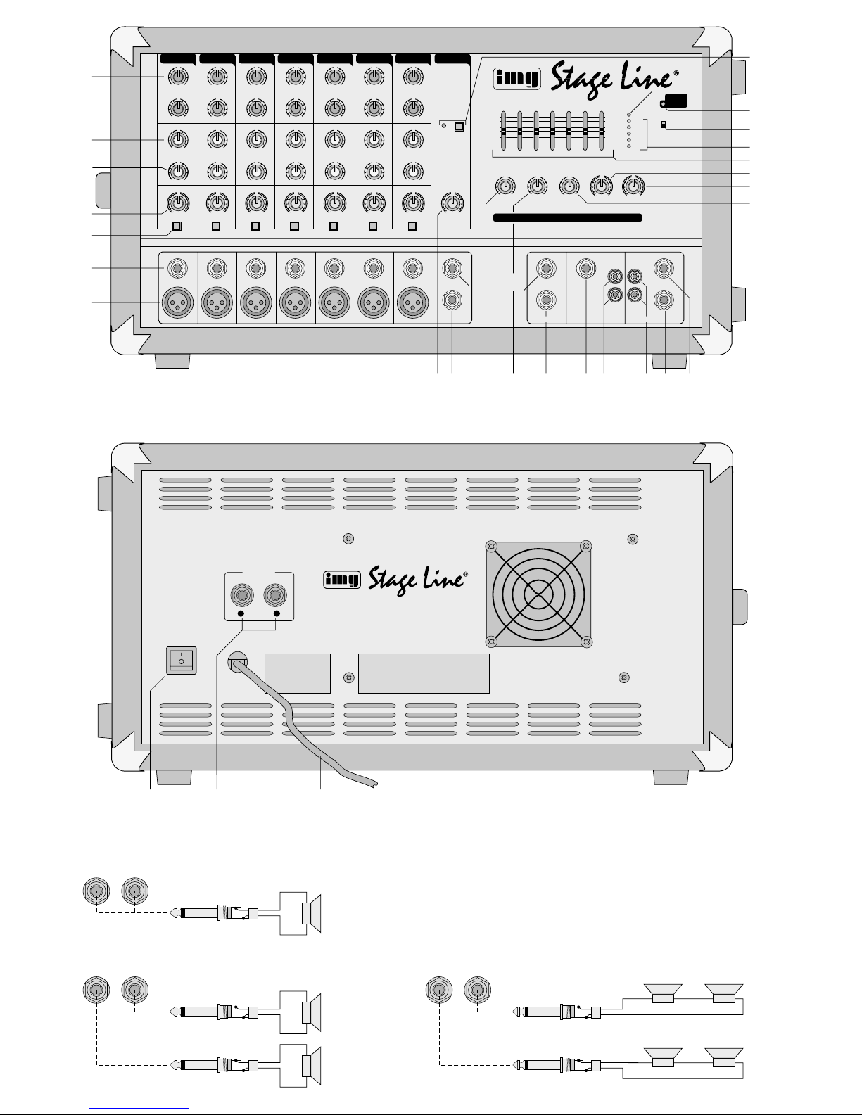
1 Übersicht der Bedienelemente und
Anschlüsse
1.1 Frontseite
1 Höhenregler HIGH, jeweils für die Kanäle 1– 7
2 Tiefenregler LOW, jeweils für die Kanäle 1–7
3 Regler MON für den Monitorweg, jeweils für die
Kanäle 1– 7:
bestimmt unabhängig vom Regler LEVEL (5)
den Pegel, mit dem das Kanalsignal auf den
Monitorweg gemischt wird [Ausgang MONITOR
(19)]
4 Regler EFF, jeweils für die Kanäle 1– 7;
bestimmt den Pegel,
a) mit dem das Kanalsignal auf die interne Hall-
spirale gegeben wird
b) mit dem das Kanalsignal abhängig von den
Reglern LEVEL (5) und EFFECT OUT (9) auf
den Ausgang OUT(11) gemischt wird
5 Pegelregler LEVEL, jeweils für die Kanäle 1– 7:
bestimmt den Pegel, mit dem das Kanalsignal
auf die Signalsumme gemischt wird [Signal für
die interne Endstufe sowie für die Ausgänge
MAIN (20) und REC (18)]
6 Taste PAD, jeweils für die Kanäle 1–7:
zum Abschwächen von hohen Eingangssignalen
um 20dB
7 Eingang LINE (6,3-mm-Klinke, sym.), jeweils für
die Kanäle 1– 7:
zum Anschluß einer Mono-Signalquelle mit LineAusgang, z.B. Musikinstrument
Hinweis: Es sollte nicht die Buchse MIC (8) desselben Kanals gleichzeitig angeschlossen werden.
8 Eingang MIC (XLR, sym.) zum Anschluß eines
Mikrofons, jeweils für die Kanäle 1– 7
Hinweis: Es sollte nicht die Buchse LINE (7) desselben Kanals gleichzeitig angeschlossen werden.
Für den Betrieb phantomgespeister Mikrofone
läßt sich mit dem Schalter PHANTOM POWER
(24) für alle Eingänge MIC gleichzeitig eine 48-VPhantomspeisung zuschalten.
9 Effekt-Send-Regler EFFECT OUT für die Buchse
OUT (11) zur Pegeleinstellung der mit den Reglern EFF (4) ausgekoppelten Kanalsignale
10 Buchse FOOT SW (6,3-mm-Klinke, 2polig) für
den Anschluß eines Fußschalters zum Ein-/Ausschalten des internen Halleffekts, siehe Kap. 4.9
11 Ausgang OUT (6,3-mm-Klinke, asym.) für die mit
den Reglern EFF (4) ausgekoppelten Kanalsignale, abhängig vom Effekt-Send-Regler
EFFECT OUT (9)
12 Regler EFFECT RTN zum Mischen des internen
Hallsignals auf die Signalsumme
(wird nicht auf den Monitorweg gegeben)
13 Regler AUX IN zum Mischen des Signals der
Buchse AUX (16) auf die Signalsumme
(wird nicht auf den Monitorweg gegeben)
14 Buchse SEND (6,3-mm-Klinke, asym.), in Ver-
bindung mit der Buchse RETURN (15) zum Einschleifen eines Effektgerätes in die Signalsumme (nicht in den Monitorweg)
15 Buchse RETURN (6,3-mm-Klinke, asym.) zum
Anschluß des Ausgangs eines Effektgerätes
Hinweis: Wird nur die Buchse RETURN angeschlossen, ist der Weg für die Signalsumme
unterbrochen (Schaltbuchse), d.h. die interne
Endstufe und die Buchse MAIN (20) erhalten
kein Signal.
16 Buchse AUX (6,3-mm-Klinke, asym.) zum An-
schluß eines Zusatzgerätes mit Line-Monoausgang, dessen Signal mit dem Regler AUX IN (13)
auf die Signalsumme gemischt werden soll
17 Eingang TAPE (Cinch-Buchsen) zum Anschluß
des Ausgangs eines Aufnahmegerätes,
siehe auch Position 29 Regler TAPEIN
Vorsicht! Keine asymmetrischen Mikrofone an-
schließen, wenn die Phantomspeisung mit dem Schalter (24) eingeschaltet ist. Diese Mikrofone können
beschädigt werden.
Please unfold page 3. Then you can always see
the operating elements and connections described.
Contents
1 Operating Elements and Connections . . . 4
1.1 Front panel . . . . . . . . . . . . . . . . . . . . . . . . . . 4
1.2 Rear panel . . . . . . . . . . . . . . . . . . . . . . . . . . 5
2 Safety Notes . . . . . . . . . . . . . . . . . . . . . . . . 5
3 Applications . . . . . . . . . . . . . . . . . . . . . . . . 5
4 Connection of the Units . . . . . . . . . . . . . . . 6
4.1 Microphones . . . . . . . . . . . . . . . . . . . . . . . . . 6
4.2 Musical instruments and
units with line output . . . . . . . . . . . . . . . . . . . 6
4.3 Speakers . . . . . . . . . . . . . . . . . . . . . . . . . . . 6
4.4 Recording unit . . . . . . . . . . . . . . . . . . . . . . . 6
4.5 Effect unit . . . . . . . . . . . . . . . . . . . . . . . . . . . 6
4.6 Power amplifier for the monitor way . . . . . . . 6
4.7 Power amplifier for the master signal . . . . . . 7
4.8 Additional unit with line output . . . . . . . . . . . 7
4.9 Foot switch . . . . . . . . . . . . . . . . . . . . . . . . . . 7
4.10 Power supply . . . . . . . . . . . . . . . . . . . . . . . . 7
5 Operation . . . . . . . . . . . . . . . . . . . . . . . . . . . 7
5.1 Mixing of the audio sources . . . . . . . . . . . . . 7
5.2 Monitor way . . . . . . . . . . . . . . . . . . . . . . . . . 7
5.3 Adding of the internal reverberation . . . . . . . 8
5.4 Using an external effect unit . . . . . . . . . . . . . 8
5.5 Recording unit and additional unit . . . . . . . . 8
6 Specifications . . . . . . . . . . . . . . . . . . . . . . . 9
Block diagram . . . . . . . . . . . . . . . . . . . . . . . 21
1 Operating Elements and Connec-
tions
1.1 Front panel
1 Control HIGH, each for channels 1 to 7
2 Control LOW, each for channels 1 to 7
3 Control MON for the monitor way, each for chan-
nels 1 to 7:
defines the level by which the channel signal is
mixed to the monitor way, independent of control
LEVEL (5) [output MONITOR (19)]
4 Control EFF, each for channels 1 to 7;
defines the level
a) by which the channels signal is fed to the
internal reverberation coil
b) by which the channel signal is added to the
output OUT (11) depending on the controls
LEVEL (5) and EFFECT OUT (9)
5 Control LEVEL, each for channels 1 to 7:
defines the level by which the channel signal is
added to the master signal [signal for the internal
power amplifier as well as for the outputs MAIN
(20) and REC (18)]
6 Button PAD, each for channels 1 to 7:
to attenuate high input signals by 20dB
7 Input LINE (6.3mm jack, bal.), each for channels
1 to 7:
to connect a mono signal source with line output,
e.g. a musical instrument
Note: jack MIC (8) of the same channel should
not be connected at the same time.
8 Input MIC (XLR, bal.) to connect a microphone,
each for channels 1 to 7
Note: jack LINE (7) of the same channel should
not be connected at the same time.
For operating phantom-powered microphones it
is possible to connect a 48V phantom power for
all inputs MIC at the same time with switch
PHANTOM POWER (24).
9 Effect Send control EFFECT OUT for jack OUT
(11) for level adjustment of the channel signals
taken off with the controls EFF (4)
10 Jack FOOT SW (6.3 mm jack, 2 poles) for the
connection of a foot switch to switch on and off
the internal reverberation effect, see chapter 4.9
11 Output OUT (6.3 mm jack, unbal.) for the chan-
nel signals taken off with the controls EFF (4),
depending on the Effect Send control EFFECT
OUT (9)
12 Control EFFECT RTN to add the internal rever-
beration signal to the master signal
(is not fed to the monitor way)
13 Control AUX IN to add the signal of jack AUX (16)
to the master signal
(is not fed to the monitor way)
14 Jack SEND (6.3mm jack, unbal.), in connection
with jack RETURN (15) to insert an effect unit
into the master signal (not into the monitor way)
15 Jack RETURN (6.3mm jack, unbal.) to connect
the output of an effect unit
Note: if only jack RETURN is connected, the way
for the master signal is interrupted (switch jack),
i. e. the internal power amplifier and jack MAIN
(20) do not get a signal
16 Jack AUX (6.3 mm jack, unbal.) to connect an
additional unit with line mono output, the signal
of which is to be added to the master signal with
control AUX IN (13)
17 Input TAPE (phono jacks) to connect the output
of a recording unit, also see item 29 control
TAPE IN
18 Output REC (phono jacks) to connect the input of
a recording unit
At the jacks the master signal is present which is,
however, not influenced by the equalizer (26), by
control MAIN (28), or by an effect unit connected
to jacks SEND (14) and RETURN (15).
Caution! Do not connect any unbalanced
microphones if the phantom power is
switched on with the switch (24).
These microphones may be damaged.
4
GB
D
A
CH

18 Ausgang REC (Cinch-Buchsen) zum Anschluß
des Eingangs eines Aufnahmegerätes
An den Buchsen liegt die Signalsumme an, die
jedoch nicht vom Equalizer (26), vom Regler
MAIN (28) oder von einem an den Buchsen
SEND (14) und RETURN (15) angeschlossenen
Effektgerät beeinflußt wird.
19 Buchse MONITOR (6,3-mm-Klinke, asym.) für
den Ausgang des Monitorwegs,
siehe auch Position 3 Regler MON und Position
27 Regler MONITOR
20 Ausgang MAIN (6,3-mm-Klinke, asym.) für die
Signalsumme
21 Taste zum Einschalten des internen Halleffekts,
mit Kontrollanzeige ON
22 LED CLIP leuchtet, wenn ein Eingang übersteu-
ert wird – den entsprechenden Regler LEVEL(5)
zurückdrehen
23 Betriebsanzeige
grün Gerät in Betrieb
rot Schutzschaltung spricht an:
3 Sekunden lang nach dem Einschalten
(Einschaltverzögerung) oder bei einem
Defekt, z. B. einem Kurzschluß am Endstufenausgang OUTPUT (31)
24 Schalter PHANTOM POWER zum Aktivieren der
48-V-Phantomspeisung,
siehe auch Position 8 Eingang MIC
25 Pegelanzeige (5 LEDs) für die Signalsumme
[interne Endstufe und Ausgang MAIN (20)]
26 7-Band-Graphic-Equalizer für die Signalsumme
[interne Endstufe und Ausgang MAIN (20)]
27 Pegelregler MONITOR für den Monitorweg
[Ausgang MONITOR (19)]
28 Pegelregler MAIN für die Signalsumme
[interne Endstufe und Ausgang MAIN (20)]
29 Regler TAPE IN zum Mischen des Signals des
Eingangs TAPE (17) auf die Signalsumme
(wird nicht auf den Monitorweg gegeben)
1.2 Rückseite
30 Ein-/Ausschalter POWER
31 Mono-Endstufenausgang für den Lautsprecher-
anschluß, siehe Abb. 3–5
(2 x 6,3-mm-Klinke, parallelgeschaltet)
32 Netzkabel zum Anschluß an eine Steckdose
(230V~/50Hz)
33 Lüfter; kühlt die Elektronik, sobald das Gerät ein-
geschaltet ist
2 Hinweise für den sicheren Gebrauch
Dieses Gerät entspricht der Richtlinie für elektromagnetische Verträglichkeit 89/ 336/ EWG und der
Niederspannungsrichtlinie 73/23/EWG.
Beachten Sie auch unbedingt die folgenden Punkte:
●
Das Gerät ist nur zur Verwendung im Innenbereich geeignet. Schützen Sie es vor Tropf- und
Spritzwasser, hoher Luftfeuchtigkeit und Hitze
(zulässiger Einsatztemperaturbereich 0– 40°C).
●
Die in dem Gerät entstehende Wärme muß durch
den Lüfter (33) abgegeben werden. Decken Sie
darum keine der Lüftungsöffnungen auf der Geräterückseite ab.
●
Stecken Sie nichts durch die Lüftungsöffnungen!
Dabei kann es zu einem elektrischen Schlag kommen.
●
Nehmen Sie das Gerät nicht in Betrieb bzw. ziehen Sie sofort den Netzstecker aus der Steckdose, wenn:
1. sichtbare Schäden am Gerät oder an der Netzanschlußleitung vorhanden sind,
2. nach einem Sturz oder ähnlichem der Verdacht
auf einen Defekt besteht,
3. Funktionsstörungen auftreten.
Lassen Sie das Gerät in jedem Fall in einer Fachwerkstatt reparieren.
●
Eine beschädigte Netzanschlußleitung darf nur
durch den Hersteller oder eine autorisierte Fachwerkstatt ersetzt werden.
●
Ziehen Sie den Netzstecker nie an der Zuleitung
aus der Steckdose.
●
Verwenden Sie für die Reinigung nur ein trockenes, weiches Tuch, auf keinen Fall Chemikalien
oder Wasser.
●
Wird das Gerät zweckentfremdet, falsch bedient
oder nicht fachgerecht repariert, kann für eventuelle Schäden keine Haftung übernommen werden.
●
Soll das Gerät endgültig aus dem Betrieb genommen werden, übergeben Sie es zur Entsorgung
einem örtlichen Recyclingbetrieb.
3 Einsatzmöglichkeiten
Der Power Mixer PMX-150R ist eine Kombination
aus einem 7-Kanal-Mischpult und einer 150-WMono-Endstufe. Er geeignet sich besonders für
Musiker und den Einsatz auf der Bühne. An die Eingangskanäle lassen sich Geräte mit Line-Ausgang
(Instrument, CD-Spieler, Tape-Deck etc.) und Mikrofone (auch phantomgespeiste) anschließen und auf
eine Signalsumme sowie auf einen Monitorweg
mischen.
Durch die interne Hallspirale kann von jedem
Eingangskanal separat ein Halleffekt auf die Signalsumme gemischt werden. Der Hall kann auch über
einen angeschlossenen Fußschalter ein- und ausgeschaltet werden. Zusätzlich bietet das Gerät über
Send- und Return-Anschlüsse die Möglichkeit, ein
externes Effektgerät einzuschleifen.
Achtung! Das Gerät wird mit lebensgefährlicher
Netzspannung (230 V~) versorgt. Nehmen Sie deshalb nie selbst Eingriffe im
Gerät vor. Durch unsachgemäßes Vorgehen besteht die Gefahr eines elektrischen Schlages. Außerdem erlischt
beim Öffnen des Gerätes jeglicher
Garantieanspruch.
Vorsicht! Die Gesamtimpedanz aller ange-
schlossenen Lautsprecher darf 4Ω
nicht unterschreiten, sonst kann die
Endstufe beschädigt werden. Siehe
auch Kapitel 4.3.
19 Jack MONITOR (6.3mm jack, unbal.) for the out-
put of the monitor way,
also see item 3 control MON and item 27 control
MONITOR
20 Output MAIN (6.3mm jack, unbal.) for the master
signal
21 Button to switch on the internal reverberation
effect, with LED ON
22 LED CLIP lights up if an input is overloaded –
turn back the corresponding control LEVEL (5)
23 Power LED
green unit is in operation
red protective circuit responds:
for 3 seconds after switching on (switch-on
delay) or in case of a defect, e.g. a short
circuit at the power amplifier OUTPUT (31)
24 Switch PHANTOM POWER to activate the 48V
phantom power, also see item 8 input MIC
25 Level indication (5 LEDs) for the master signal
[internal power amplifier and output MAIN (20)]
26 7-band graphic equalizer for the master signal
[internal power amplifier and output MAIN (20)]
27 Level control MONITOR for the monitor way
[output MONITOR (19)]
28 Level control MAIN for the master signal
[internal power amplifier and output MAIN (20)]
29 Control TAPE IN to add the signal of the input
TAPE (17) to the master signal
(is not fed to the monitor way)
1.2 Rear panel
30 On/off switch POWER
31 Mono power amplifier output for the speaker
connection, see figs. 3 to 5
(2 x 6.3mm jack, connected in parallel)
32 Mains cable for connection to a mains socket
(230V~/50Hz)
33 Fan; cools the electronics as soon as the unit is
switched on
2 Safety Notes
The unit corresponds to the directive for electromagnetic compatibility 89/ 336 /EEC and to the low
voltage directive 73/23/EEC.
The following items must be observed in any case:
●
The unit is suitable for indoor use only. Protect it
against dripping water and splash water, high air
humidity and heat (admissible ambient temperature range 0– 40°C).
●
The heat generated within the unit must be carried
off by the fan (33). Therefore, do not cover the air
vents of the housing with any objects.
●
Do not insert anything through the air vents! This
may result in an electric shock.
●
Do not operate unit or immediately disconnect the
plug from the mains socket
1. if there is visible damage to the unit or to the
mains cable,
2. if a defect might have occurred after the unit
was dropped or suffered a similar accident,
3. if malfunctions occur.
In any case the unit must be repaired by skilled
personnel.
●
A damaged mains cable must be replaced by the
manufacturer or by skilled personnel only.
●
Never pull the mains cable to disconnect the
mains plug from the socket.
●
For cleaning only use a dry, soft cloth, by no
means chemicals or water.
●
If the unit is used for other purposes than originally
intended, if it is not correctly operated or not repaired by skilled personnel, no liability for any
damage will be accepted.
●
If the unit is to be put out of operation definitively,
take it to a local recycling plant for disposal.
●
Important for U.K. Customers!
The wires in this mains lead are coloured in accordance with the following code:
green/yellow = earth
blue = neutral
brown = live
As the colours of the wires in the mains lead of this
appliance may not correspond with the coloured
markings identifying the terminals in your plug,
proceed as follows:
1. The wire which is coloured green and yellow
must be connected to the terminal in the plug
which is marked with the letter E or by the earth
symbol , or coloured green or green and
yellow.
2. The wire which is coloured blue must be connected to the terminal which is marked with the
letter N or coloured black.
3. The wire which is coloured brown must be connected to the terminal which is marked with the
letter L or coloured red.
Warning
-
This appliance must be earthed.
3 Applications
The power mixer PMX-150R is a combination of a
7-channel mixer and a 150W mono power amplifier.
It is especially suitable for musicians and stage
applications. It is possible to connect to the input
channels units with line output (musical instrument,
CD player, tape deck, etc.) and microphones (also
phantom-powered) and to add them to a master signal as well as to a monitor way.
Due to the internal reverberation coil it is possible
to add a reverberation effect to the master signal
separately from each input channel. The reverberation can also be switched on and off via a connected
Attention! The unit is supplied with hazardous
mains voltage (230 V~). Leave servicing to skilled personnel only. Inexpert
handling may cause an electric shock
hazard. Furthermore, any guarantee
claim will expire if the unit has been
opened.
Caution! The total impedance of all connected
speakers must not be lower than 4Ω,
otherwise the power amplifier may be
damaged. Also see chapter 4.3.
5
GB
D
A
CH

4 Geräte anschließen
Vor dem Anschluß bzw. vor dem Verändern von Anschlüssen den PMX-150R und die anzuschließenden Geräte ausschalten.
4.1 Mikrofone
1) Benötigen die verwendeten Mikrofone keine
Phantomspeisung, den Schalter PHANTOM
POWER (24) in die Position OFF stellen. In diesem Fall können sowohl symmetrisch als auch
asymmetrisch beschaltete Mikrofone angeschlossen werden.
2) Für den Betrieb von phantomgespeisten Mikrofonen den Schalter PHANTOM POWER in die
Position ON stellen. An allen XLR-Buchsen MIC
(8) liegt die 48-V-Phantomspeisung an.
3) Die Mikrofone an die XLR-Buchsen MIC (8) anschließen.
Hinweis: Die Eingänge lassen sich nicht zwischen
den Buchsen MIC (8) und LINE (7) umschalten.
Darum in jedem Kanal entweder die XLR-Buchse
MIC oder die Klinkenbuchse LINE anschließen.
4.2 Instrumente und Geräte mit Line-Ausgang
Signalquellen mit Line-Monoausgang (z. B. Instrumente) an die Buchsen LINE (7) anschließen. Beim
Anschluß von Stereo-Geräten (CD-Spieler, TapeDeck etc.) diese auf Mono schalten oder einen entsprechenden Adapter (z.B. NTA-169, MCA-300 von
MONACOR) verwenden, sonst ist ein Kanal in der
Phase gedreht (Stereo-Differenzsignal).
Hinweis: In jedem Eingangskanal entweder die
Klinkenbuchse LINE (7) oder die XLR-Buchse MIC
(8) anschließen.
4.3 Lautsprecher
Den bzw. die Lautsprecher je nach gewünschter
Lautsprecherkonfiguration (Abb. 3 – 5) an den Ausgang OUTPUT (31) anschließen. Die beiden Buchsen des Endstufenausgangs sind parallelgeschaltet.
1. Soll ein Lautsprecher angeschlossen werden,
diesen an eine der beiden Buchsen OUTPUT(31)
anschließen – siehe Abb. 3. Die Impedanz des
Lautsprechers muß mindestens 4Ω betragen.
Ein 4-Ω-Lautsprecher muß mit mindestens
150W
RMS belastbar sein, ein 8-Ω-Lautsprecher
mit mindestens 104W
RMS.
2. Sollen zwei Lautsprecher angeschlossen werden, je einen Lautsprecher an eine der Buchsen
(31) anschließen – siehe Abb. 4. Die Impedanz
der einzelnen Lautsprecher muß mindestens 8Ω
betragen, und jeder der Lautsprecher muß mit
mindestens 75W
RMS belastbar sein.
3. Sollen vier Lautsprecher angeschlossen wer-
den, jeweils zwei in Reihe schalten, und jede
Lautsprechergruppe an eine der Buchsen (31)
anschließen – siehe Abb. 5. Die Impedanz aller
Lautsprecher sollte gleich sein und für jeden
Lautsprecher mindestens 4Ω betragen.
Bei Verwendung von 4-Ω-Lautsprechern muß
jeder mit mindestens 38W
RMS belastbar sein, bei
8-Ω-Lautsprechern jeder mit mindestens 26W
RMS.
4.4 Aufnahmegerät
1) Für Tonaufnahmen den Eingang eines Aufnahmegerätes an die Cinch-Buchsen REC (18) anschließen. Hier liegt die Signalsumme an, die jedoch nicht vom Equalizer (26), vom Regler MAIN
(28) oder von einem an den Buchsen SEND (14)
und RETURN (15) angeschlossenen Effektgerät
beeinflußt wird.
2) Die Aufnahme läßt sich über die interne Endstufe
des PMX-150R abhören. Dazu den Ausgang des
Aufnahmegerätes an die Cinch-Buchsen TAPE
(17) anschließen. Das Signal wird über den Regler TAPE IN (29) auf die Signalsumme gemischt.
4.5 Effektgerät
Es gibt zwei Möglichkeiten ein Effektgerät an den
PMX-150R anzuschließen. Das Effektsignal wird
dabei auf die Signalsumme geführt, jedoch nicht auf
den Ausgang MONITOR (19).
1. Den Eingang des Effektgerätes an die Buchse
SEND (14) anschließen und den Ausgang an die
Buchse RETURN (15). Bei dieser Anschlußart ist
das Effektgerät in die Signalsumme eingeschleift.
Über den PMX-150R ist kein Einfluß auf den
Effektanteil möglich, d.h. alle Einstellungen müssen am Effektgerät erfolgen.
Hinweis: Wird nur die Buchse RETURN angeschlossen, ist der Weg für die Signalsumme
unterbrochen (Schaltbuchse), d.h. die interne
Endstufe und die Buchse MAIN (20) erhalten
kein Signal.
2. Den Eingang des Effektgerätes an die Buchse
OUT (11) anschließen und den Ausgang an die
Buchse AUX (16). Mit den Reglern EFF (4) wird
für jeden Eingangskanal der Signalanteil, der auf
das Effektgerät gegeben werden soll, eingestellt
und mit dem Regler EFFECT OUT (9) der
Gesamtpegel. Das vom Effektgerät zurückgeführte Signal wird über den Regler AUX IN (13)
auf die Signalsumme gemischt.
Hinweis: Weil mit den Reglern EFF sowohl der
Signalanteil der Eingangskanäle für die interne
Hallspirale als auch der Signalanteil für die
Buchse OUT eingestellt wird, muß ggf. der
interne Halleffekt mit der Taste (21) ausgeschaltet oder mit dem Regler EFFECT RTN (12) korrigiert werden.
4.6 Endverstärker für den Monitorweg
Um das Signal des Monitorwegs über Lautsprecher
wiederzugeben, den Line-Eingang eines Endverstärkers an die Buchse MONITOR (19) anschließen.
Hier liegt das Signal an, welches mit den Reglern
MON (3) aus den Eingangskanälen 1– 7 ausgekoppelt und mit dem Regler MONITOR (27) im Pegel
eingestellt wird.
Vorsicht! Ist die Phantomspeisung eingeschal-
tet, dürfen keine asymmetrischen
Mikrofone angeschlossen werden.
Anderenfalls können diese Mikrofone
beschädigt werden.
foot switch. In addition, via the Send and Return
connections the unit offers the facility to insert an
external effect unit.
4 Connection of the Units
Prior to the connection or changing of connections
switch off the PMX-150R and the units to be connected.
4.1 Microphones
1) If the microphones used do not need a phantom
power, set switch PHANTOM POWER (24) to
position OFF. In this case both balanced as well
as unbalanced microphones can be connected.
2) For the operation of phantom-powered microphones set switch PHANTOM POWER to position ON. The 48 V phantom power is present at
all XLR jacks MIC (8).
3) Connect the microphones to the XLR jacks MIC
(8).
Note: the inputs cannot be switched between jacks
MIC (8) and LINE (7). Therefore, connect to each
channel either the XLR jack MIC or the 6.3mm jack
LINE.
4.2 Musical instruments and units with line
output
Connect signal sources with line mono output (e.g.
musical instruments) to the jacks LINE (7). When
connecting stereo units (CD player, tape deck, etc.)
switch them to mono or use a corresponding adapter (e.g. NTA-169, MCA-300 by MONACOR), otherwise a channel is phase-reversed (stereo differential
signal).
Note: connect either the 6.3mm jack LINE (7) or the
XLR jack MIC (8) to each input channel.
4.3 Speakers
Connect the speaker/s to the OUTPUT (31) according to the desired speaker configuration (figs. 3 to 5).
Both jacks of the power amplifier output are connected in parallel.
1. For connecting one speaker, connect it to one of
the two jacks OUTPUT (31) – see fig. 3. The
impedance of the speaker must be 4Ω as a minimum.
A4Ω speaker must have a power capability
of 150W
RMS as a minimum, an 8Ω speaker
104W
RMS as a miminum.
2. For connecting two speakers, connect one
speaker each to one of the jacks (31) – see fig. 4.
The impedance of the individual speakers must
be 8 Ω as a minimum, and each speaker must
have a power capability of 75 W
RMS as a mimi-
mum.
3. For connecting four speakers, connect two
speakers each in series, and connect each
speaker group to one of the jacks (31) – see
fig. 5. The impedance of all speakers should be
the same and at least 4Ω for each speaker.
When using 4Ω speakers, each speaker must
have a power capability of 38 W
RMS as a mini-
mum, in case of 8 Ω speakers, each speaker at
least 26W
RMS.
4.4 Recording unit
1) For audio recordings connect the input of a recording unit to the phono jacks REC (18). At
these jacks the master signal is present which is,
however, not influenced by the equalizer (26),
control MAIN (28), or an effect unit connected to
the jacks SEND (14) and RETURN (15).
2) The recording can be monitored via the internal
power amplifier of the PMX-150R. For this purpose connect the output of the recording unit to
the phono jacks TAPE (17). The signal is added
to the master signal via control TAPE IN (29).
4.5 Effect unit
There are two facilities to connect an effect unit to
the PMX-150R. The effect signal is directed to the
master signal, however, not to output MONITOR
(19).
1. Connect the input of the effect unit to jack SEND
(14), and the output to jack RETURN (15). With
this kind of connection the effect unit is inserted
into the master signal. Via the PMX-150R no
influence is possible on the effect amount , i.e. all
adjustments have to be made at the effect unit.
Note: if only jack RETURN is connected, the way
for the master signal is interrupted (switch jack),
i. e. the internal power amplifier and jack MAIN
(20) get no signal.
2. Connect the input of the effect unit to jack OUT
(11), and the output to jack AUX (16). With the
controls EFF (4) adjust for each input channel the
signal amount, which is to be fed to the effect
unit, and with control EFFECT OUT (9) the total
level. The signal fed back from the effect unit is
added to the master signal via control AUX IN
(13).
Note: as the signal amount of the input channels
for the internal reverberation coil as well as the
signal amount for jack OUT is adjusted with the
controls EFF, the internal reverberation effect
must be switched off with button (21) or be corrected with control EFFECT RTN (12), if necessary.
4.6 Power amplifier for the monitor way
To reproduce the signal of the monitor way via
speakers, connect the line input of a power amplifier
to jack MONITOR (19). At this jack the signal is present which is taken off with the controls MON (3) from
the input channels 1 to 7 and which is level-adjusted
with control MONITOR (27).
Caution! If the phantom power is switched on,
no unbalanced microphones must be
connected. Otherwise these microphones may be damaged.
6
GB
D
A
CH

4.7 Endverstärker für die Signalsumme
Wird zusätzlich zur internen Endstufe ein Endverstärker für weitere Lautsprecher benötigt, den LineEingang des Endverstärkers an die Buchse MAIN
(20) anschließen. Hier liegt die Signalsumme an, die
zur internen Endstufe gelangt.
4.8 Zusatzgerät mit Line-Ausgang
Sind alle Eingangskanäle belegt, kann ggf. zusätzlich ein Gerät mit Line-Monoausgang an die Buchse
AUX (16) angeschlossen werden. Beim Anschluß
eines Stereo-Gerätes dieses auf Mono schalten
oder einen entsprechenden Adapter (z.B. NTA-169,
MCA-300 von MONACOR) verwenden, sonst ist nur
ein Kanal zu hören. Das Signal wird über den Regler AUX IN (13) auf die Signalsumme gemischt.
4.9 Fußschalter
Der interne Halleffekt kann über einen Fußschalter
an- und ausgeschaltet werden. Den Fußschalter
(z.B. FS-60A, PFS-28/SW von MONACOR) an die
Buchse FOOT SW (10) anschließen.
Anschluß eines Fußschalters ➅
Damit der interne Halleffekt über den Fußschalter
an- und ausgeschaltet werden kann, die Taste (21)
im Bedienfeld REVERB drücken. Die LED ON neben
der Taste leuchtet. Wird der Fußschalterkontakt geschlossen, ist der Halleffekt ausgeschaltet. Wird der
Kontakt geöffnet, ist der Halleffekt eingeschaltet.
Das Ein-/Ausschalten über den Fußschalter wird
nicht durch die LED ON angezeigt. Sie leuchtet
ständig.
4.10 Stromversorgung
Nachdem alle Geräte an den PMX-150R angeschlossen sind, den Netzstecker des Anschlußkabels (32) in eine Steckdose (230V~/50Hz) stecken.
5 Bedienung
1) Vor dem Einschalten des Power Mixers sollten
die Regler MONITOR (27) und MAIN (28) auf
Null gestellt werden, um eventuelle Einschaltgeräusche zu vermeiden.
2) Das Gerät mit dem Ein-/Ausschalter POWER (30)
auf der Geräterückseite einschalten. Der Lüfter
(33) läuft an, die Betriebsanzeige (23) leuchtet rot
und schaltet nach ca. 3 Sekunden auf Grün um
(Einschaltverzögerung).
Sollte die Betriebsanzeige nicht auf Grün
umschalten, liegt ein Defekt vor, z.B. Kurzschluß
am Endstufenausgang OUTPUT (31). In diesem
Fall den PMX-150R wieder ausschalten und den
Fehler beheben.
3) Die angeschlossenen Geräte einschalten.
4) Beim Ausschalten der Anlage immer zuerst den
PMX-150R abschalten.
5.1 Mischen der Tonquellen
1) Zuerst zur Grundeinstellung
alle Höhenregler HIGH (1) und
alle Tiefenregler LOW (2)
in die Mittelstellung auf Null drehen.
Die Regler MON (3), EFF (4), LEVEL (5) sowie
die Regler EFFECT OUT (9), EFFECT RTN (12),
AUX IN (13) und TAPE IN (29)
ganz nach links auf Null drehen.
Alle Schieberegler des Equalizers (26)
in die Mittelposition auf Null stellen.
Alle Tasten PAD (6) drücken. Dadurch sind die
Eingänge auf eine geringere Empfindlichkeit
geschaltet und werden nicht gleich bei hohen
Pegeln übersteuert.
2) Auf alle angeschlossenen Eingänge 1 –7 ein Signal geben (Mikrofondurchsage, Testsignal oder
Musikstück).
3) Damit über die angeschlossenen Lautsprecher
ein Signal gehört werden kann, den Summenregler MAIN (28) zunächst etwas aufdrehen.
4) Zuerst die Eingangssignale, die am lautesten zu
hören sein sollen, mit den Reglern LEVEL (5) auf
die Signalsumme mischen, und mit dem Regler
MAIN die Summenlautstärke einstellen. Wenn
ein Eingang übersteuert wird, leuchtet die rote
Übersteuerungsanzeige CLIP (22) auf. Den entsprechenden Regler LEVEL zurückdrehen.
Muß einer oder mehrere der Eingangsregler
LEVEL sehr weit aufgedreht werden, um den gewünschten Pegel zu erreichen, die entsprechenden Regler zuerst wieder auf Null drehen. Dann
die zugehörige Taste PAD(6) lösen, wodurch der
Kanal auf eine höhere Eingangsempfindlichkeit
geschaltet wird. Den Regler LEVEL wieder aufdrehen.
5) Die übrigen Kanäle, die ebenfalls zu hören sein
sollen, mit den zugehörigen Reglern LEVEL entsprechend dazumischen.
6) Für jeden Eingangskanal getrennt die Höhen mit
dem Regler HIGH (1) und die Tiefen mit dem Regler LOW (2) bei Bedarf anheben oder absenken.
7) Den Klang für die Signalsumme [angeschlossene
Lautsprecher und Ausgang MAIN (20)] mit dem
7-Band-Graphic-Equalizer (26) optimal einstellen.
8) Die Pegelanzeige (25) zeigt den Pegel für die
Signalsumme an. Der Pegel sollte bei den lautesten Passagen 0dB nicht überschreiten bzw. die
gelbe LED „+3“ nur kurz aufleuchten. Anderenfalls treten Signalverzerrungen auf. Dann den
Regler MAIN entsprechend zurückdrehen.
5.2 Monitorweg
Auf den Monitorweg werden die Eingangssignale
der Kanäle 1– 7 gemischt, die zur Bühnenbeschallung benötigt werden. Als Ausgang dient die Buchse
MONITOR (19), an die über einen separaten Endverstärker (siehe Kap. 4.6) Monitorlautsprecher
angeschlossen werden.
1) Mit den Reglern MON (3) die Eingangssignale
auf den Monitorweg mischen.
2) Mit dem Regler MONITOR (27) den Pegel des
Monitorsignals einstellen.
Hinweis: Der interne Hall oder ein angeschlossenes Effektgerät wird nicht über den Monitorweg
ON
OFF
REVERB
4.7 Power amplifier for the master signal
If in addition to the internal power amplifier, a power
amplifier is required for further speakers, connect
the line input of the power amplifier to jack MAIN
(20). At this jack the master signal is present which
arrives at the internal power amplifier.
4.8 Additional unit with line output
If all input channels are connected, a unit with line
mono output can in addition be connected to jack
AUX (16), if required. When connecting a stereo
unit, switch this unit to mono or use a corresponding
adapter (e. g. NTA-169, MCA-300 by MONACOR),
otherwise only one channel can be heard. The signal
is added to the master signal via control AUX IN (13).
4.9 Foot switch
The internal reverberation effect can be switched on
and off via a foot switch. Connect the foot switch
(e. g. FS-60A, PFS-28 / SW by MONACOR) to jack
FOOT SW (10).
Connection of a foot switch ➅
For switching the internal reverberation effect on
and off via the foot switch, press the button (21) in
the operating section REVERB. The LED ON next to
the button lights up. If the foot switch contact is
closed, the reverberation effect is switched off. If the
contact is opened, the reverberation effect is
switched on. Switching on and off via the foot switch
is not indicated by the LED ON. It lights continuously.
4.10 Power supply
After all units have been connected to the PMX150R, connect the mains plug of the cable (32) to a
mains socket (230V~/50Hz).
5 Operation
1) Prior to switching on the power mixer, the controls MONITOR (27) and MAIN (28) should be set
to zero to avoid possible switching-on noise.
2) Switch on the unit with the POWER switch (30)
on the rear side of the unit. The fan (33) starts to
operate, the Power LED (23) lights red and
switches to green after approx. 3 seconds (switchon delay).
If the Power LED should not switch to green,
there is a defect, e. g. short circuit at the power
amplifier OUTPUT (31). In this case switch off the
PMX-150R again, and eliminate the error.
3) Switch on the connected units.
4) When disconnecting the unit, always switch off
the PMX-150R first.
5.1 Mixing of the audio sources
1) For the basic setting, first turn
all HIGH controls (1) and
all LOW controls (2) to mid-position to zero.
Turn the controls MON (3), EFF (4), LEVEL(5) as
well as the controls EFFECT OUT (9), EFFECT
RTN (12), AUX IN (13), and TAPE IN (29) to the
left stop to zero.
Set all sliding controls of the equalizer (26) to
mid-position to zero.
Press all buttons PAD (6). Thus, the inputs are
switched to a lower sensitivity and are not overloaded in case of high levels.
2) Feed a signal to all connected inputs 1 to 7
(microphone announcement, test signal, or
music piece).
3) To be able to hear a signal via the connected
speakers, slightly turn up the master control
MAIN (28) for the time being.
4) First add the input signals, which are to be heard
at highest level, to the master signal with the controls LEVEL (5), and adjust the volume of the
master signal with control MAIN. If an input is
overloaded, the red overload indication CLIP (22)
lights up. Turn back the corresponding control
LEVEL.
If one or several of the input controls LEVEL
have to be turned up very much to reach the desired level, first set the corresponding controls to
zero again. Then disengage the corresponding
button PAD (6) which switches the channel to a
higher input sensitivity. Then turn up the control
LEVEL again.
5) Add the remaining channels, which are likewise
to be heard, with the corresponding controls
LEVEL accordingly.
6) If required, boost or attenuate the high frequencies with the control HIGH (1) and the low frequencies with the control LOW (2) separately for
each input channel.
7) Adjust the sound for the master signal [connected speakers and output MAIN (20)] with the
7-band graphic equalizer (26) in an optimum way.
8) The level indication (25) shows the level for the
master signal. The level should not exceed 0dB
for music peaks or the yellow LED “+3” should
only shortly light up. Otherwise there will be signal distortions. Then turn back control MAIN correspondingly.
5.2 Monitor way
The input signals of channels 1 to 7 which are required for PA stage applications are added to the
monitor way. Jack MONITOR (19) serves as an output to which monitor speakers are connected via a
separate power amplifier (see chapter 4.6).
1) Add the input signals to the monitor way with the
controls MON (3).
2) Adjust the level of the monitor signal with the control MONITOR (27).
Note: the internal reverberation or a connected
effect unit is not directed via the monitor way. Also
the equalizer (26) does not influence the monitor
way.
ON
OFF
REVERB
7
GB
D
A
CH
 Loading...