

Page 1
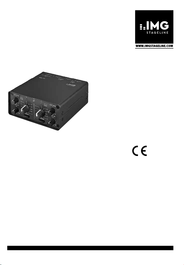
Mikrofonvorverstärker
Microphone Preamplifier
MPA-202
Bestell-Nr. • Order No. 32.0710
BEDIENUNGSANLEITUNG
INSTRUCTION MANUAL
MODE D’EMPLOI
ISTRUZIONI PER L’USO
GEBRUIKSAANWIJZING
MANUAL DE INSTRUCCIONES
INSTRUKCJA OBSŁUGI
ELECTRONICS FOR SPECIALISTS ELECTRONICS FOR SPECIALISTS ELECTRONICS FOR SPECIALISTS
Page 2

Deutsch ............Seite 4
English ............Page 6
Français ............Page 8
Italiano ............Pagina 10
Nederlands .........Pagina 12
Español ............Página 14
Polski ..............Strona 16
ELECTRONICS FOR SPECIALISTS ELECTRONICS FOR SPECIALISTS ELECTRONICS FOR SPECIALISTS
2
Page 3
1 2 3 4 5 6
FINE TUNE
-
CH 1
0
GAIN
40
35
5 +5
dB
30
LOW CU T
60
25
20
15
Hz
CH 2 OUTPUT CH 2 INPUT C H 1 INPUT CH 1 OUTPUT
BAL. BAL. BAL. BAL.
INVE RT
240
3
2 1
15V~
POWE R
ON
OFF
7 8 9 10 11 12
Blockschaltbild eines Kanals
Block diagram of one channel
PK PKON
45
50
40
55
35
60
30
65
25
70
dB dB
3
1 2
20
1 2
PHAN TOM
ON
OFF
INVE RT
3
CH 2
FINE TUNE
0
GAIN
45
50
55
-
5 +5
dB
60
LOW CU T
60
65
70
15
240
Hz
➀
3
2 1
CH 1CH 2
OUTPUT
UNBAL.
➁
2
1
MIC
INPUT
BAL
AC
INPUT
15V~
+
MIC
+12V
–
AMP
20
POWER
SUPPLY
GAIN
dB
3
PHANTOM
SUBSONIC
FILTER
18dB /OCT.
PEAK LED
70
+
15Hz/
LO CUT
FILTER
PHASE
SELECT
FINE TUNE
OUTPUT
DRIVER
2
3
1
LINE
OUTPUT
BAL
LINE
OUTPUT
UNBAL
➂
3
Page 4

Mikrofonvorverstärker
Diese Bedienungsanleitung richtet sich an Benutzer
ohne besondere Fachkenntnisse. Bitte lesen Sie die Anleitung vor dem Betrieb gründlich durch und heben Sie
Deutsch
Deutsch
sie für ein späteres Nachlesen auf.
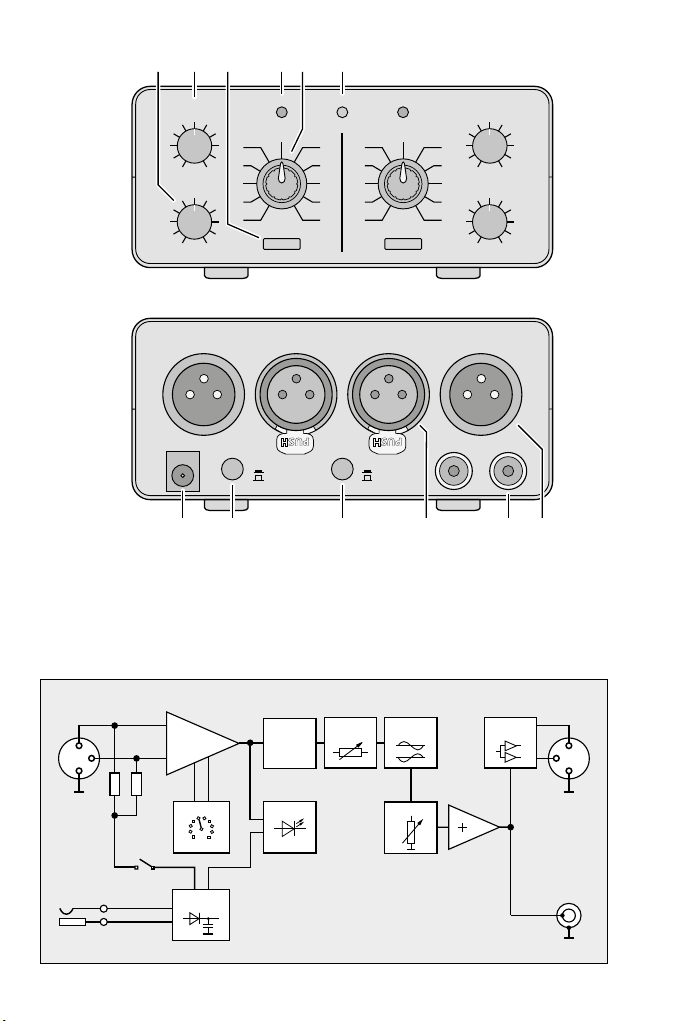
ren Seite 3 finden Sie alle beschriebenen Bedien elemente
und Anschlüsse.
Im folgenden Text wird der Kanal 1 beschrieben. Die
Bedienung des Kanals 2 ist vollkommen identisch.
1 Übersicht der Anschlüsse und
Bedienelemente
1 Regler LOW CUT für den Hochpass:
Die Signalanteile unterhalb der eingestellten Frequenz werden unterdrückt
2 Regler FINE TUNE für die Feineinstellung
der Verstärkung (±5 dB)
3 Taste zum Invertieren des Mikrofonsignals;
bei gedrückter Taste wird das Signal invertiert
4 Spitzenwertanzeige PK (Peak): leuchtet,
wenn der Kanal optimal ausgesteuert ist
Die LED darf bei den lautesten Passagen
kurz aufleuchten. Leuchtet sie länger, den
Regler FINE TUNE (2) oder den Schalter
GAIN (5) zurückdrehen.
5 Stufenschalter GAIN zur groben Einstel-
lung der Verstärkung
(20 – 70 dB in 5-dB-Schritten)
6 Betriebsanzeige ON
7 Anschlussbuchse „15 V~“ für den beilie-
genden Steckertrafo zur Stromversorgung
8 Ein- /Ausschalter POWER
9 Taste PHANTOM zum Einschalten der
Phantomspeisung (+12 V)
Vorsicht! Bei gedrückter Taste ist die 12-VPhantomspeisung eingeschaltet. Es dürfen in diesem Fall keine Mikrofone mit
asymmetrischem Ausgang angeschlossen
sein, da diese Mikrofone beschädigt werden können.
10 Mikrofoneingang
(XLR, servosymmetrisch)
11 Line-Ausgang (Cinch, asymmetrisch)
12 Line-Ausgang (XLR, servosymmetrisch)
2 Wichtige Hinweise zur Sicherheit
Die Geräte (Mikrofonvorverstärker und Steckertrafo) entsprechen allen relevanten Richtlinien der EU und tragen deshalb das
chen.
4
Auf der ausklappba-
WARNUNG
trafo vor. Durch unsachgemäßes Vorgehen besteht die Gefahr eines elektrischen Schlages.
Verwenden Sie die Geräte nur im Innenbe-
•
reich und schützen Sie sie vor Tropf- und
Spritzwasser, hoher Luftfeuchtigkeit und
Hitze (zulässiger Einsatztemperaturbereich
0 – 40 °C).
Auch wenn der Verstärker ausgeschaltet
•
ist, hat der an einer Steckdose angeschlossene Steckertrafo einen geringen Stromverbrauch.
Nehmen Sie den Verstärker nicht in Betrieb
•
und ziehen Sie sofort den Steckertrafo aus
der Steckdose, wenn:
1. sichtbare Schäden am Steckertrafo oder
2. nach einem Sturz oder Ähnlichem der
3. Funktionsstörungen auftreten.
Lassen Sie die Geräte in jedem Fall in einer
Fachwerkstatt reparieren.
Verwenden Sie für die Reinigung nur ein
•
trockenes, weiches Tuch, auf keinen Fall
Chemikalien oder Wasser.
Wird der Verstärker oder der Steckertrafo
•
zweckentfremdet, falsch angeschlossen,
nicht richtig bedient oder nicht fachgerecht
repariert, kann keine Haftung für daraus
resultierende Sach- oder Personenschäden
und keine Garantie für die Geräte übernommen werden.
Der Steckertrafo wird mit lebensgefährlich hoher Netzspannung
versorgt. Nehmen Sie deshalb niemals selbst Eingriffe am Stecker-
am Verstärker vorhanden sind,
Verdacht auf einen Defekt besteht,
Sollen die Geräte endgültig aus dem
Betrieb genommen werden, übergeben Sie sie zur umweltgerechten
Entsorgung einem örtlichen Recyclingbetrieb.
3 Verwendungsmöglichkeiten
Der MPA-202 ist ein zweikanaliger Mikrofonvorverstärker in Low-Noise-Halbleitertechnik
für den Einsatz auf der Bühne und im Tonstudio sowie im Homerecording- und Multimedia- Bereich.
Die Mikrofoneingänge sind als servosymmetrisch beschaltete XLR-Buchsen ausgelegt. Für
phantomgespeiste Mikrofone lässt sich eine
12-V-Phantomspannung einschalten. Als Aus-
-Zeigänge sind servosymmetrisch beschaltete XLR-
Page 5

Buchsen und Cinch-Buchsen (asymmetrisch)
vorhanden. Ein 15-Hz-Infraschallfilter und ein
einstellbares Hochpassfilter (15 Hz bis 240 Hz)
unterdrücken störende Frequenzanteile.
4 Gerät anschließen
Den MPA-202 und die anzuschließenden Geräte ausschalten, bevor die Anschlüsse hergestellt oder verändert werden.
Tipps
1. Die XLR-Ein- und Ausgänge sollten symmetrisch angeschlossen werden, weil so besser
Störungen (durch eine lange Anschlussleitung aufgefangen) unterdrückt werden als
bei asymmetrischem Anschluss.
2. Bei asymmetrischem Anschluss sollten an
den XLR-Steckern die Kontakte 1 (Masse)
und 3 (negatives Signal) überbrückt sein.
Durch die servosymmetrische Schaltung
wird dann automatisch der 6-dB-Pegelverlust ausgeglichen, der sonst bei asymmetrischem Anschluss entsteht.
Anschluss
1) Die Mikrofone an die Eingänge INPUT (10)
anschließen. Die XLR-Buchsen besitzen eine
Verriegelung. Zum Herausziehen eines Steckers den PUSH-Hebel drücken.
2) Die Line-Eingänge des nachfolgenden Gerätes (z. B. Verstärker, Mischpult) an die
XLR- Ausgänge (12) und / oder an die CinchAusgänge (11) anschließen.
3) Zuletzt den Kleinspannungsstecker des
beiliegenden Steckertrafos in die Buchse
„15 V~“ (7) stecken und den Trafo in eine
Steckdose (230 V/ 50 Hz).
5 Bedienung
1) Bei Verwendung phantomgespeister Mikrofone muss die Phantomspeisung (+12 V)
eingeschaltet werden. Dazu die Taste
PHANTOM (9) hineindrücken.
Vorsicht! Wird die Phantomspeisung eingeschaltet, dürfen keine Mikrofone mit
asymmetrischem Ausgang angeschlossen
sein, da diese beschädigt werden können.
2) Erst nach dem Aktivieren der Phantomspeisung das Gerät mit dem Ein- /Ausschalter POWER (8) einschalten. Es leuchtet die
grüne Betriebsanzeige ON (6). Danach das
nachfolgende Gerät einschalten.
3) Mit dem Drehschalter GAIN (5) die Verstärkung des Mikrofonsignals an den erforder-
lichen Eingangspegel des nachfolgenden
Gerätes anpassen. Zur Feineinstellung den
Regler FINE TUNE (2) betätigen. Die LED
PK (4) zur Spitzenwertanzeige darf bei
den lautesten Passagen kurz aufleuchten.
Leuchtet sie länger, den Regler FINE TUNE
oder den Schalter GAIN zurückdrehen.
4) Um tieffrequente Störsignale zu unterdrücken, mit dem Regler LOW CUT (1) die Frequenz einstellen, bei der der Übertragungsbereich beginnen soll.
5) Muss die Phasenlage des Mikrofonsignals
um 180° gedreht (invertiert) werden, die
Taste INVERT (3) hineindrücken. Im Zweifelsfall lässt sich durch wechselweises Drücken und Lösen der Taste die optimale
Schalterstellung ermitteln. Diese ist z. B. bei
bester Basswiedergabe im Summensignal
der Signalquellen (Mikrofone) gegeben.
6) Nach dem Betrieb den MPA-202 mit der
Taste POWER ausschalten. Wird er längere
Zeit nicht gebraucht, auch den Steckertrafo
aus der Steckdose ziehen. Anderenfalls
wird unnötig Strom verbraucht.
6 Technische Daten
Frequenzbereich:. . . . . . . 20 Hz (±1 dB) bis
Eingänge
Empfindlichkeit bei
1 V Ausgangsspannung: 0,16 – 150 mV einstellbar
Impedanz: . . . . . . . . . . 4,4 kΩ bei sym. Anschluss,
Phantomspeisung: . . . . +12 V
Ausgänge
XLR, servosym.: . . . . . . 1 V/14 V max., 100
Cinch, asymmetrisch: . . 1 V/ 7 V max., 600
Verstärkung: . . . . . . . . . . 15 – 75 dB
Kanaltrennung: . . . . . . . . > 80 dB
Störabstand: . . . . . . . . . . > 68 dB, unbewertet
Klirrfaktor:. . . . . . . . . . . . < 0,01 %
Hochpassfilter (Low Cut): 15 – 240 Hz, 6 dB / Oktave
Infraschallfilter: . . . . . . . . 15 Hz, 18 dB / Oktave
Stromversorgung: . . . . . . 15 V (~) / 300 mA über
Abmessungen, Gewicht: . 116 × 55 × 135 mm, 1,2 kg
Änderungen vorbehalten.
Diese Bedienungsanleitung ist urheberrechtlich für
MONACOR® INTERNATIONAL GmbH & Co. KG geschützt. Eine Reproduktion für eigene kommerzielle
Zwecke – auch auszugsweise – ist untersagt.
20 kHz(±0,5 dB)
2,2 kΩ bei asym. Anschluss
Ω
Ω
beiliegenden Steckertrafo an
230V/ 50 Hz / 5 VA
Deutsch
5
Page 6
Microphone Preamplifier
These instructions are intended for users without any
specific technical knowledge. Please read these instruc-
English
tions carefully prior to operating the unit and keep them
for later reference.
tions de scribed can be found on the fold-out page 3.
In the following text, channel 1 is described. The operation of channel 2 is completely identical.
1 Operating Elements
andConnections
1 Control LOW CUT for the high pass:
The signal parts below the adjusted frequency are suppressed
2 Control FINE TUNE for the fine adjustment
of the amplification (±5 dB)
3 Button to invert the microphone signal;
with the button pressed, the signal will be
inverted
4 Peak value indicator PK: lights up when
the channel is perfectly adjusted
The LED must shortly light up with music
peaks. If it lights up for a longer time,
turn back the control FINE TUNE (2) or the
switch GAIN (5).
5 Step switch GAIN for coarse adjustment of
the amplification (20 – 70 dB in 5 dB steps)
6 Power indicator ON
7 Connection jack “15 V~” for the supplied
plug-in transformer for the power supply
8 POWER switch
9 Button PHANTOM for switching on the
phantom power (+12 V)
Attention! With the button pressed, the
12 V phantom power is switched on. In
this case, no microphones with unbalanced output must be connected; otherwise, they may be damaged.
10 Microphone input (XLR, servo-balanced)
11 Line output (RCA, unbalanced)
12 Line output (XLR, servo-balanced)
2 Important Safety Notes
The units (microphone preamplifier and
plug-in transformer) correspond to all relevant directives of the EU and are therefore
marked with
6
All operating elements and connec-
.
WARNING
The units are suitable for indoor use only.
•
Pro tect them against dripping water and
splash water, high air humidity, and heat
(admissible ambient temperature range
0 – 40 °C).
Even when the amplifier is switched off, the
•
plug-in transformer connected to a mains
socket has a low current consumption.
Do not set the amplifier into operation and
•
immediately disconnect the plug-in transformer from the mains socket if
1. there is visible damage to the plug-in
2. a defect might have occurred after a drop
3. malfunctions occur.
The units must in any case be repaired by
skilled personnel.
For cleaning only use a dry, soft cloth; never
•
use chemicals or water.
No guarantee claims for the amplifier or
•
the plug-in transformer and no liability for
any resulting personal damage or material
damage will be accepted if they are used for
other purposes than originally intended, if
they are not correctly connected or operated, or if they are not re paired in an expert way.
The plug-in transformer uses dangerous mains voltage. Leave servicing to skilled personnel only.
Inexpert handling may result in
electric shock.
transformer or the amplifier,
or similar accident,
If the units are to be put out of operation definitively, take them to a local
recycling plant for a disposal which is
not harmful to the environment.
3 Applications
The MPA-202 is a 2-channel microphone preamplifier in low-noise semiconductor technology to be used on stage and in the sound recording studio as well as for home recording
and multimedia applications.
The microphone inputs are designed as
servo-balanced XLR jacks. For phantompowered microphones, the 12 V phantom
power can be switched on. Servo-balanced
XLR jacks and unbalanced RCA jacks are available as outputs. A 15 Hz infrasound filter and
an adjustable high pass filter (15 Hz to 240 Hz)
suppress interfering frequency parts.
Page 7

4 Connecting the Unit
Switch off the MPA-202 and the units to be
connected before making or changing any
connections.
Hints
1. The XLR input and output connections
should be balanced; this will suppress interferences (caused by long connection
cables) in a better way than unbalanced
connections do.
2. For unbalanced connections, bridge contacts 1 (ground) and 3 (negative signal) of
the XLR plugs. The servo-balanced circuit
will automatically make up for the 6 dB
level loss that occurs with unbalanced
connections.
Connection
1) Connect the microphones to the inputs
INPUT (10). The XLR jacks have a latch. To
pull out a plug, press the PUSH lever.
2) Connect the line inputs of the subsequent
unit (e. g. amplifier, mixer) to the XLR outputs (12) and / or the RCA inputs (11).
3) Finally connect the low-voltage plug of the
supplied plug-in transformer to the jack
“15 V~” (7) and the transformer to a socket
(230 V/ 50 Hz).
5 Operation
1) When using phantom-powered micro-
phones, the phantom power (+12 V) must
be switched on. For this purpose, press the
button PHANTOM (9).
Attention! If the phantom power is switched on, no microphones with unbalanced
output must be connected; they may be
damaged.
2) Do not switch on the unit with the POWER
switch (8) before activating the phantom
power. The green LED ON (6) lights up.
Then switch on the subsequent unit.
3) Use the rotary switch GAIN (5) to adapt the
amplification of the microphone signal to
the required input level of the subsequent
unit. For fine adjustment, use the control
FINE TUNE (2). The peak value LED indicator PK (4) must shortly light up with music
peaks. If it lights up for a longer time, turn
back the control FINE TUNE or the switch
GAIN.
4) To suppress low-frequency interference signals adjust, with the control LOW CUT (1),
the frequency at which the transmission
range is to start.
5) If the phase of the microphone signal must
be turned by 180° (inverted), press the
button INVERT (3). If in doubt, alternately
press and release the button to determine
the best switch position; this will be, for example, when the bass reproduction in the
master signal of the signal sources (microphones) is best.
6) After operation, switch off the MPA-202
with the POWER button. If it is not used for
a long er time, also disconnect the plug-in
transformer from the socket. Otherwise
there will be an unnecessary power consumption.
6 Specifications
Frequency range:. . . . . . . 20 Hz (±1 dB) to
Inputs
sensitivity at
1 V output voltage . . . . 0.16 – 150 mV adjustable
impedance: . . . . . . . . . 4.4 kΩ with bal. connection,
phantom power:. . . . . . +12 V
Outputs
XLR, servobal.: . . . . . . . 1 V/14 V max., 100
RCA, unbalanced:. . . . . 1 V/ 7 V max., 600
Amplification: . . . . . . . . . 15 – 75 dB
Channel seperation: . . . . > 80 dB
S / N ratio:. . . . . . . . . . . . . > 68 dB, unweighted
THD: . . . . . . . . . . . . . . . . < 0.01 %
High pass filter (Low Cut): 15 – 240 Hz, 6 dB / oct.
Infrasound filter: . . . . . . . 15 Hz, 18 dB / oct.
Power supply: . . . . . . . . . 15 V (~) / 300 mA via sup-
Dimensions, weight: . . . . 116 × 55 × 135 mm, 1.2 kg
Subject to technical modifications.
All rights reserved by MONACOR ® INTERNATIONAL
GmbH & Co. KG. No part of this instruction manual
may be reproduced in any form or by any means for
any commercial use.
20 kHz (±0.5 dB)
2.2 kΩ with unbal. connection
Ω
Ω
plied plug-in transformer
at 230 V/ 50 Hz / 5 VA
English
7
Page 8
Préamplificateur micro
Cette notice s‘adresse aux utilisateurs sans connaissances techniques particulières. Veuillez lire la notice
avant le fonctionnement et conservez-la pour pouvoir
Français
vous y reporter ultérieurement. Vous trouverez sur la
page 3, dépliable, les éléments et branchements décrits.
Le texte suivant décrit le canal 1. L’utilisation du canal
2 est identique.
1 Eléments et branchements
1 Réglage LOW CUT pour le passe-haut :
les parties de signal sous la fréquence réglée sont éliminées.
2 Réglage FINE TUNE pour le réglage précis
de l’amplification (±5 dB)
3 Touche pour inverser le signal micro ; le
signal est inversé si la touche est enfoncée.
4 LED PK (Peak) d’affichage des valeurs crête:
brille si le canal est réglé de manière optimale.
La LED peut briller brièvement pour les
passages de musique les plus forts. Si elle
brille plus longtemps, tournez le réglage
FINE TUNE (2) ou le sélecteur GAIN en
arrière.
5 Sélecteur GAIN pour un réglage grossier
de l’amplification (20 – 70 dB en paliers de
5 dB)
6 Témoin de fonctionnement ON
7 Prise de branchement «15 V~» pour le
transformateur livré
8 Interrupteur POWER Marche /Arrêt
9 Touche PHANTOM pour allumer l’alimen-
tation fantôme +12 V
Attention ! Si la touche est enfoncée,
l’alimentation fantôme 12 V est allumée.
Dans ce cas, vous ne devez pas brancher
de microphones avec sortie asymétrique,
ils peuvent être endommagés.
10 Entrée micro (XLR, servo-symétrique)
11 Sortie Ligne (RCA, asymétrique)
12 Sortie Ligne (XLR, servo-symétrique)
2 Conseils d’utilisation et de sécurité
Les appareils (préamplificateur micro et transformateur) répondent à toutes les directives
nécessaires de l’Union européenne et portent
donc le symbole .
8
AVERTISSEMENT
en cas de mauvaise manipulation, vous pourriez subir une décharge électrique.
Les appareils ne sont conçus que pour une
•
utilisation en intérieur. Protégez-les des
éclaboussures, de tout type de projections
d’eau, de l’humidité élevée et de la chaleur
(température ambiante admissible 0 – 40 °C).
Même lorsque l’amplificateur est éteint, le
•
transformateur a une faible consommation
s’il reste relié au secteur.
Ne faites jamais fonctionner l’amplificateur
•
et débranchez immédiatement le transformateur lorsque :
1. des dommages sur le transformateur ou
l’amplificateur apparaissent,
2. après une chute ou accident similaire...,
l’appareil peut présenter un défaut,
3. des dysfonctionnements apparaissent.
Dans tous les cas, les dommages doivent
être réparés par un technicien spécialisé.
Pour le nettoyage, utilisez un chiffon sec et
•
doux, en aucun cas de produits chimiques
ou d’eau.
Nous déclinons toute responsabilité en cas
•
de dommages corporels ou matériels résultants si l’amplificateur ou le transformateur
sont utilisés dans un but autre que celui pour
lequel ils ont été conçus, s’ils ne sont pas correctement branchés ou utilisés ou s’ils ne
sont pas réparés par une personne habilitée;
de même, la garantie deviendrait caduque.
Le transformateur est alimenté par une tension dangereuse. Ne touchez jamais
l’intérieur de l’appareil car,
Lorsque les appareils sont définitivement retirés du service, vous devez
les déposer dans une usine de recyclage de proximité pour contribuer à
leur élimination non polluante.
CARTONS ET EMBALLAGE
PAPIER À TRIER
3 Possibilités d’utilisation
Le MPA-202 est un préamplificateur micro
2 canaux, technologie semiconducteurs Low
Noise pour une utilisation sur scène, en enregistrement studio, tout comme en multimédia
et enregistrement Home Recording.
Les entrées micro sont configurées comme
prises XLR servo-symétriques. Pour les micro-
Page 9

phones à alimentation fantôme, on peut allumer une alimentation fantôme 12 V. En sorties, des prises XLR servo-symétriques et RCA
asymétriques sont prévues. Un filtre infrasons
15 Hz et un filtre passe-haut réglable (15 Hz à
240 Hz) permettent d’éliminer les parties de
fréquences perturbatrices.
4 Branchement de l'appareil
Eteignez le MPA-202 et les appareils reliés
avant d’effectuer les branchements ou de
modifier les branchements existants.
Remarques
1. Les entrées et sorties XLR devraient être
branchées en symétrique ; dans ce cas, les
interférences (générées par un long câble)
sont mieux éliminées que par un branchement asymétrique.
2. Dans le cas d’un branchement asymétrique,
les contacts 1 (masse) et 3 (signal négatif)
des fiches XLR devraient être bridgés. Le
circuit servo-symétrique automatiquement
compense la perte de niveau de 6 dB qui apparaît avec un branchement asymétrique.
Branchement
1) Reliez les microphones aux entrées INPUT
(10). Les prises XLR possèdent un verrouillage. Pour déverrouiller la fiche, enfoncez
le levier PUSH.
2) Reliez les entrées Ligne de l’appareil suivant
(p. ex. table de mixage, amplificateur) aux
sorties XLR (12) et / ou aux sorties RCA (11).
3) Enfin, reliez la fiche d’alimentation du transformateur livré à la prise «15 V~» (7) et reliez
le transformateur à une prise 230 V/ 50 Hz
.
5 Fonctionnement
1) Si vous utilisez des microphones à alimentation fantôme, l’alimentation fantôme
(+12 V) doit être allumée. Pour ce faire, enfoncez la touche PHANTOM (9).
Attention ! Si l’alimentation fantôme est
allumée, il ne faut pas brancher de microphones avec sortie asy métrique, ils peuvent
être endommagés.
2) N’allumez l’appareil avec l’interrupteur
POWER (8) qu’une fois l’alimentation fantôme activée. Le témoin de fonctionnement vert ON (6) brille. Allumez ensuite
l’appareil suivant.
3) Avec le sélecteur GAIN (5), adaptez l’amplification du signal micro au niveau d’entrée nécessaire de l’appareil suivant. Pour
un réglage précis, utilisez le réglage FINE
TUNE(2). La LED PK (4) pour les valeurs de
crête devrait briller brièvement pour les
passages de musique les plus forts. Si elle
brille plus longtemps, tournez le réglage
FINE TUNE ou le sélecteur GAIN en arrière.
4) Pour éliminer les signaux perturbateurs des
fréquences basses, réglez avec le réglage
LOW CUT (1) la fréquence à laquelle la
plage de transmission doit débuter.
5) Si la phase du signal micro doit être tournée
de 180° (inversée), enfoncez la touche INVERT (3). En cas de doute, on peut déterminer la position optimale en enfonçant puis
relâchant alternativement la touche. La position est optimale avec une reproduction
meilleure des graves dans le signal master
des sources de signaux (microphones).
6) Après le fonctionnement, éteignez le MPA202 avec la touche POWER. En cas de non
utilisation prolongée, débranchez également le transformateur du secteur sinon un
courant inutile est consommé.
6 Caractéristiques techniques
Bande passante :. . . . . . . 20 Hz (±1 dB) à
Entrées
Sensibilité pour une ten sion de sortie de 1 V :. . 0,16 – 150 mV réglable
Impédance :. . . . . . . . . 4,4 kΩ pour branche-
Alimentation fantôme : +12 V
Sorties
XLR, servo-sym. : . . . . . 1 V/14 V max., 100 Ω
RCA, asymétrique :. . . . 1 V/ 7 V max., 600 Ω
Amplification :. . . . . . . . . 15 – 75 dB
Séparation des canaux : . > 80 dB
Rapport signal / bruit : . . . > 68 dB, non pondéré
Taux de distorsion :. . . . . < 0,01 %
Filtre passe-haut
(Low Cut) :
Filtre infrasons :. . . . . . . . 15 Hz, 18 dB / oct.
Alimentation : . . . . . . . . . 15 V (~) / 300 mA par
Dimensions, poids : . . . . . 116 × 55 × 135 mm, 1,2 kg
Tout droit de modification réservé.
Notice d’utilisation protégée par le copyright de
MONACOR ® INTERNATIONAL GmbH & Co. KG. Toute
reproduction même partielle à des fins commerciales
est interdite.
. . . . . . . . . . . 15 – 240 Hz, 6 dB / oct.
20 kHz(±0,5 dB)
mentsym., 2,2 kΩ pour
branchement asym.,
transformateur livré relié à
230 V/ 50 Hz / 5 VA
Français
9
Page 10
Preamplificatore per Microfoni
Queste istruzioni sono rivolte all‘utente senza conoscenze tecniche specifiche. Vi preghiamo di leggerle
attentamente prima della messa in funzione e di con-
Italiano
servarle per un uso futuro.
pletamente, vedrete sempre gli elementi di comando e i
collegamenti descritti.
Il testo seguente descrive il canale 1. Il funzionamento
del canale 2 è perfettamente identico.
1 Panoramica
1 Regolatore LOW CUT per il passaalto:
Le parti del segnale inferiori alla frequenza impostata vengono soppresse
2 Regolatore FINE TUNE per la regolazione
fine dell’amplificazione (±5 dB)
3 Tasto per invertire il segnale del micro-
fono; con il tasto premuto, il segnale viene
invertito
4 Spia dei picchi PK (Peak): è accesa se il
canale è regolato in modo otti male.
Il LED può accendersi brevemente con i
passaggi più forti. Se rimane acceso più a
lungo, occorre abbassare il regolatore FINE
TUNE (2) o il commutatore GAIN (5).
5 Commutatore GAIN per la regolazione
grossolana dell’amplificazione (20 – 70 dB
in passi di 5 dB)
6 Spia di funzionamento ON
7 Presa “15 V~” per il trasformatore di ali-
mentazione inseribile direttamente in
prese standard, in dotazione
8 Interruttore on / off POWER
9 Tasto PHANTOM per attivare l’alimenta-
zione phantom (+12 V)
Attenzione! Con il tasto premuto, l’alimentazione phantom 12 V è attivata. In
questo caso non devono essere collegati
dei microfoni con uscita asimmetrica perché possono subire dei danni.
10 Ingresso microfono (XLR, servosimmetrico)
11 Uscita Line (RCA, asimmetrica)
12 Uscita Line (XLR, servosimmetrica)
2 Avvertenze di sicurezza
Gli apparecchi (preamplificatore per microfoni
e trasformatore) sono conformi a tutte le direttive rilevanti dell’UE e pertanto porta la sigla
AVVERTIMENTO
10
A pagina 3, se aperta com-
Il trasformatore inseribile direttamente in prese standard
è alimentato con pericolosa
tensione di rete. Non inter-
venire mai personalmente al suo interno.
Esiste il pericolo di una scarica elettrica.
Far funzionare gli apparecchi solo all’in-
•
terno di locali e proteggerli dall’acqua
gocciolante e dagli spruzzi d’acqua, da alta
umidità dell’aria e dal calore (temperatura
d’impiego ammessa fra 0 e 40 °C).
Anche quando l’amplificatore è spento,
•
il trasformatore inserito in una presa consuma un po’ di corrente.
Non mettere in funzione l’amplificatore e
•
stac care subito il trasformatore dalla presa
di rete se:
1. il trasformatore o l’amplificatore presentano dei danni visibili;
2. dopo una caduta o dopo eventi simili sussiste il sospetto di un difetto;
3. gli apparecchi non funzionano correttamente.
Per la riparazione rivolgersi sempre ad
un’officina competente.
Per la pulizia usare solo un panno morbido,
•
asciutto; non impiegare in nessun caso prodotti chimici o acqua.
Nel caso d’uso improprio, di collegamenti
•
sbagliati, d’impiego scorretto o di riparazione non a regola d’arte dell’amplificatore
o del trasformatore, non si assume nessuna
re spon sabilità per eventuali danni consequenziali a persone o a cose e non si assume
nessuna garanzia per gli apparecchi.
Se si desidera eliminare gli apparecchi definitivamente, consegnarli
per lo smaltimento ad un’istituzione
locale per il riciclaggio.
3 Possibilità d’impiego
L’MPA-202 è un preamplificatore per microfoni a 2 canali con la tecnica di semiconduttori low noise per l’impiego sul palcoscenico e
nello studio di registrazione, ma anche per il
home-recording e per multimedia.
Gli ingressi per microfoni sono delle prese
XLR servosimmetriche. Per i microfoni con alimentazione phantom si può attivare l’alimen-
.
tazione phantom di 12 V. Le uscite sono delle
prese XLR servosimmetriche e RCA (asimmetriche). Un filtro infrasuoni di 15 Hz e un passaalto regolabile (15 Hz a 240 Hz) sopprimono le
frequenze indesiderate.
Page 11

4 Collegamento degli apparecchi
Prima di eseguire o modificare i collegamenti
occorre spegnere l’MPA-202 e gli apparecchi
da collegare.
N. B.:
1. Gli ingressi e le uscite XLR dovrebbero essere a collegamento simmetrico perché in
questo modo è più facile, rispetto ad un
collegamento asimmetrico, sopprimere
delle interferenze (captate da un lungo
cavo di collegamento).
2. In caso di collegamento asimmetrico, i
contatti 1 (massa) e 3 (segnale negativo)
delle spine XLR dovrebbero essere ponticellati. Il collegamento servosimmetrico
compensa al lora automaticamente la perdita di 6 dB del livello che altrimenti si registra con un collegamento asimmetrico.
Collegamento
1) Collegare i microfoni con gli ingressi INPUT
(10). Le prese XLR sono equipaggia te con
un blocco. Per sfilare la spina, premere la
levetta PUSH.
2) Collegare gli ingressi Line dell’apparecchio
a valle (p. es. amplificatore, mixer) con le
uscite XLR (12) e / o con le uscite RCA (11).
3) Alla fine inserire lo spinotto per alimenta-
zione DC del trasformatore in dotazione
nella presa “15 V~” (7) e inserire il trasformatore direttamente in una presa di rete
(230 V/ 50 Hz).
5 Funzionamento
1) Se si usano microfoni con alimentazione
phantom occorre attivare l’alimentazione
phantom (+12 V). Per fare ciò premere il
tasto PHANTOM (9).
Attenzione! Se l’alimentazione phantom
12 V è attivata, non devono essere collegati dei microfoni con uscita asimmetrica
perché possono subire dei danni.
2) Accendere l’apparecchio con l’interruttore
on / off POWER (8) solo dopo aver attivato
l’alimentazione phantom. Si accende la spia
verde di funzionamento ON (6). Quindi accendere l’apparecchio a valle.
3) Con il commutatore GAIN (5) adattare l’am-
plificazione del segnale del microfono al livello d’ingresso richiesto dall’apparecchio a
valle. Per la regolazione fine usare il regolatore FINE TUNE (2). Il LED PK (4) che indica i
picchi deve accendersi solo brevemente nei
passaggi più forti. Se rimane acceso più a
lungo, abbassare il regolatore FINE TUNE o
il commutatore GAIN.
4) Con il regolatore LOW CUT (1) impostare
la frequenza dalla quale deve iniziare la riproduzione per sopprimere le interferenze
a bassa frequenza.
5) Se occorre invertire di 180° la fase del segna le del microfono, premere il tasto INVERT (3). Nel dubbio, premendo e lascian do
più volte il tasto si può trovare la posizio ne
ottimale del tasto. Tale condizione si ottiene, per esempio, con la riproduzione
migliore dei bassi nel segnale delle somme
delle sorgenti (cioè dei microfoni).
6) Dopo l’uso, spegnere l’ MPA-202 con il tasto
POWER. Se non viene usato per un periodo
prolungato, staccare anche il trasformatore
dalla presa di rete per non consumare inutilmente della corrente.
6 Dati tecnici
Gamma passante: . . . . . . . .20 Hz (±1 dB) a
Ingressi
Sensibilità con
tensione di uscita 1 V: . . . 0,16 – 150 mV regolabile
Impedenza: . . . . . . . . . . .4,4 kΩ con collegamento
Alimentazione phantom: . +12 V
Uscite
XLR, servosimm.: . . . . . . . 1 V/14 V max., 100
RCA, asimmetrica: . . . . . . 1 V/ 7 V max., 600
Amplificazione: . . . . . . . . . . 15 – 75 dB
Separazione canali: . . . . . . .> 80 dB
Rapporto S / R: . . . . . . . . . . . > 68 dB, non valutato
Fattore di distorsione: . . . . . < 0,01 %
Filtro passaalto
(Low Cut):
Filtro infrasuoni: . . . . . . . . . 15 Hz, 18 dB / ott.
Alimentazione: . . . . . . . . . . 15 V (~) / 300 mA tramite
Dimensioni, peso:
Con riserva di modifiche tecniche.
La MONACOR ® INTERNATIONAL GmbH & Co. KG
si riserva ogni diritto di elaborazione in qualsiasi
forma delle presenti istruzioni per l’uso. La riproduzione – anche parziale – per propri scopi commerciali
è vietata.
. . . . . . . . . . . . . . 15 – 240 Hz, 6 dB / ott.
. . . . . . . .116 × 55 × 135 mm, 1,2 kg
20 kHz(±0,5 dB)
simmetrico, 2,2 kΩ con
collegamento asimmetrico
Ω
Ω
trasformatore con
230 V/ 50 Hz / 5 VA
in dotazione
Italiano
11
Page 12
Microfoonvoorversterker
Deze handleiding is bedoeld voor gebruikers zonder bijzondere vakkennis. Lees de handleiding grondig door,
alvorens het apparaat in gebruik te nemen, en bewaar
ze voor latere raadpleging. Op de uitklapbare pagina3
Nederlands
vindt u een overzicht van de bedieningselementen en de
aansluitingen.
In de onderstaande tekst wordt kanaal 1 beschreven. De
bediening van kanaal 2 is volkomen identiek.
1 Overzicht van de bedienings-
elementen en aansluitingen
1 Regelaar LOW CUT voor het hoogdoor-
laatfilter:
De signaalsterkten onder de ingestelde
frequentie worden onderdrukt
2 Regelaar FINE TUNE voor de fijninstelling
van de versterking (±5 dB)
3 Toets voor inverteren van het microfoon-
signaal; bij ingedrukte toets wordt het
signaal geïnverteerd
4 Piekwaarde-indicator PK (Peak): licht op,
wanneer het kanaal optimaal is uitgestuurd
De LED mag bij de luidste passages even
oplichten. Als ze langer oplicht, draait u
de regelaar FINE TUNE (2) of de schakelaar
GAIN (5) terug.
5 Niveauschakelaar GAIN voor grove instel-
ling van de versterking (20 – 70 dB in stappen van 5 dB)
6 POWER-LED ON
7 Aansluitingsjack “15 V~” voor de bij-
geleverde stekkertransformator die de
voedings spanning verzorgt
8 POWER-schakelaar
9 Toets PHANTOM voor het inschakelen van
de fantoomvoeding (+12 V)
Opgelet! Bij ingedrukte toets is de fantoomvoeding van 12 V ingeschakeld. U
mag in geen geval microfoons met ongebalanceerde uitgang aansluiten op de
XLR-contacten. U zou de microfoons immers kunnen beschadigen.
10 Microfooningang (XLR, servogebalanceerd)
11 Lijnuitgang (Cinch, ongebalanceerd)
12 Lijnuitgang (XLR, servogebalanceerd)
2 Belangrijke veiligheidsvoorschriften
De apparaten (microfoonversterker en stekkertransformator) zijn in overeenstemming
met alle relevante EU-Richtlijnen en dragen
daarom het kenmerk
12
.
WAARSCHUWING
onzorgvuldige ingrepen loopt u het risico
van elektrische schokken.
De apparaten zijn uitsluitend geschikt voor
•
ge bruik binnenshuis; vermijd druip- en
spatwater, plaatsen met een hoge vochtigheid en uitzonderlijk warme plaatsen
(toegestaan omgevingstemperatuurbereik:
0 – 40 °C).
Ook wanneer de versterker is uitgescha-
•
keld, verbruikt de stekkertransformator die
op een stopcontact is aangesloten, een geringe hoeveelheid stroom.
Schakel de versterker niet in en trek onmid-
•
dellijk de stekkertransformator uit het stopcontact, wanneer:
1. de stekkertransformator of de versterker
zichtbaar beschadigd zijn
2. er een defect zou kunnen optreden nadat
een apparaat bijvoorbeeld gevallen is,
3. een apparaat slecht functioneert.
De apparaten moeten in elk geval hersteld
worden door een gekwalificeerd vakman.
Gebruik voor de reiniging uitsluitend een
•
droge, zachte doek. Gebruik in geen geval
chemicaliën of water.
In geval van ongeoorloofd of verkeerd ge-
•
bruik, verkeerde aansluiting resp. bediening of van herstelling door een niet-gekwalificeerd persoon vervalt de garantie op
de apparatuur en de verantwoordelijkheid
voor hieruit resulterende materiële of lichamelijke schade.
Wanneer de apparaten definitief uit
bedrijf worden genomen, bezorg ze
dan voor verwerking aan een plaatselijk recyclagebedrijf.
De netspanning van de
stekkertransformator is levensgevaarlijk. Open het
apparaat niet, want door
3 Toepassingen
De MPA-202 is een tweekanaals microfoonversterker met Low Noise halfgeleidertechniek, en vindt toepassing op het podium, in
de geluidsstudio en in het homerecording- en
multimediasegment.
De microfooningangen zijn uitgevoerd als
servogebalanceerd bedrade XLR-jacks. Voor
microfoons met fantoomvoeding kunt u een
fantoomspanning van 12 V inschakelen. Als
uitgangen zijn servogebalanceerde XLR-jacks
Page 13

en ongebalanceerde cinch-jacks beschikbaar.
Een infrasoonfilter van 15 Hz en een regelbare
hoogdoorlaatfilter (15 Hz tot 240 Hz) onderdrukken storende frequenties.
4 Het apparaat aansluiten
Alvorens aansluitingen tot stand te brengen
of te wijzigen, schakelt u de MPA-202 en de
aan te sluiten apparaten uit.
Tips
1. Sluit de XLR-in- en uitgangen gebalanceerd
aan, omdat storingen (door een lange aansluitleiding opgevangen) op deze manier
beter worden onderdrukt dan bij een ongebalanceerde aansluiting.
2. Bij ongebalanceerde aansluiting moeten de
contacten 1 (massa) en 3 (negatief signaal)
van de XLR-stekkers overbrugd zijn. Dankzij de servogebalanceerde schakeling wordt
zo automatisch het niveauverlies van 6 dB
gecompenseerd dat anders bij ongebalanceerde aansluiting ontstaat.
Aansluiting
1) Sluit de microfoons aan op de ingangen
INPUT (10). De XLR-jacks zijn uitgerust met
een vergrendeling. Om een stekker uit te
trekken, drukt u op de PUSH-hendel.
2) Sluit de lijningangen van het nageschakelde apparaat (bv. versterker, mengpaneel) aan op de XLR-uitgangen (12) en / of
op de cinch-jacks (11).
3) Plug ten slotte de laagspanningsstekker
van de bijgeleverde stekkertransformator
in de jack “15 V~” (7) en de transformator
in een stopcontact (230 V/ 50 Hz).
5 Bediening
1) Bij gebruik van microfoons met fantoomvoed ing moet de fantoomvoeding (+12 V)
worden ingeschakeld. Druk hiervoor de
toets PHANTOM (9) in.
Opgelet! Als de fantoomvoeding wordt
ingeschakeld, mogen geen microfoons met
ongebalanceerde uitgang zijn aangesloten.
Ze kunnen immers worden beschadigd.
2) Schakel het apparaat pas na het activeren
van de fantoomvoeding in met de POWERschakelaar (8). De groene POWER-LED ON
(6) licht op. Schakel vervolgens het nageschakelde apparaat in.
3) Gebruik de draaischakelaar GAIN (5) om de
versterking van het microfoonsignaal aan
het vereiste ingangsniveau van het nageschakelde apparaat aan te passen. Draai
met de regelaar FINE TUNE (2) voor een
nauwkeuriger instelling. De LED PK (4) voor
de piekwaarde-indicatie mag bij de luidste
passages even oplichten. Als ze langer oplicht, draait u de regelaar FINE TUNE of de
schakelaar GAIN terug.
4) Om laagfrequente stoorsignalen te onderdrukken, stelt u met de regelaar LOW CUT
(1) de frequentie in, vanaf welke u het
transmissiebereik wilt laten beginnen.
5) Als de faseverhouding van het microfoonsignaal 180° moet worden gedraaid (geïnverteerd), drukt u de toets INVERT (3) in.
In geval van twijfel, kunt u de optimale
schakelaarinstelling zoeken door de toets
afwisselend in te drukken en los te laten.
Deze instelling vindt u bijvoorbeeld bij een
optimale basweergave in het mastersignaal
van de signaalbronnen (microfoons).
6) Schakel de MPA-202 na gebruik uit met
de toets POWER. Wanneer u het apparaat
langere tijd niet gebruikt, trek dan ook de
stekkertransformator uit het stopcontact.
Anders wordt onnodig stroom verbruikt.
6 Technische gegevens
Frequentiebereik:. . . . . . . 20 Hz (±1 dB) tot
Ingangen
Gevoeligheid bij
1 V uitgangsspanning: . 0,16 – 150 mV regelbaar
Impedantie: . . . . . . . . . 4,4 kΩ bij gebal. aansluiting,
Fantoomvoeding: . . . . . +12 V
Uitgangen
XLR, servogebalanceerd: 1 V/14 V max, 100
Cinch, ongebalanceerd: 1 V/ 7 V max, 600
Versterking:. . . . . . . . . . . 15 – 75 dB
Kanaalscheiding:. . . . . . . > 80 dB
Signaal / Ruis-verhouding: > 68 dB, niet geëvalueerd
THD: . . . . . . . . . . . . . . . . < 0,01 %
Hoogdoorlaatfilter
(Low Cut):
Infrasoonfilter:. . . . . . . . . 15 Hz, 18 dB / oct.
Voedingsspanning: . . . . . 15 V (~) / 300 mA via bijgele-
Afmetingen, gewicht: . . . 116 × 55 × 135 mm, 1,2 kg
Wijzigingen voorbehouden.
. . . . . . . . . . . . 15 – 240 Hz, 6 dB / oct.
20 kHz (±0,5 dB)
2,2 kΩ bij ongebalanceerde
aansluiting
Ω
Ω
verde stekkertransformator
op 230V/ 50 Hz / 5 VA
Nederlands
13
Page 14
Preamplificador de micrófono
Estas instrucciones van dirigidas a usuarios sin ningún
conocimiento técnico específico. Lea atentamente estas
Español
instrucciones antes de utilizar el aparato y guárdelas
para usos posteriores. Puede encontrar todos los elementos de funcionamiento y las conexiones que se describen
en la página 3 desplegable.
El siguiente texto describe el canal 1. La utilización del
canal 2 es idéntica.
1 Elementos de funcionamiento
yconexiones
1 Reglaje LOW CUT para el pasa alto:
las partes de señal bajo la frecuencia ajustada están eliminadas
2 Reglaje FINE TUNE para el ajuste fino de la
amplificación (±5 dB)
3 Tecla para invertir la señal micro; la señal
se invierte si la tecla está pulsada
4 Indicador LED PK (Peak) para indicar los
picos: Brilla si el canal está ajustado de
manera óptima
El LED puede brillar brevemente para
picos de música. Si brilla más tiempo, baje
el reglaje FINE TUNE (2) o el interruptor
GAIN(5).
5 Interruptor GAIN para el ajuste tosco de la
amplificación (20 – 70 dB en niveles de 5 dB)
6 Indicador ON
7 Toma de conexión “15 V~” para el trans-
formador de enchufe entregado
8 Interruptor POWER
9 Tecla PHANTOM para encender la alimen-
tación phantom +12 V
¡Atención! Si la tecla está pulsada, la alimentación phantom 12 V está encendida.
En este caso, no debe conectar micros con
salida asimétrica, pueden dañarse.
10 Entrada micro (XLR, servo-simétrica)
11 Salida Línea (RCA, asimétrica)
12 Salida Línea (XLR, servo-simétrica)
2 Notas de seguridad
Los aparatos (preamplificador micro y transformador de enchufe) cumplen con todas las
directivas relevantes de la UE y por lo tanto
están marcados con el símbolo
14
.
ADVERTENCIA
Los aparatos están adecuados para su apli-
•
cación sólo en interiores. Protéjalos de
goteos y salpicaduras, elevada humedad
del aire y calor (rango de temperatura ambiente admisible: 0 – 40 ºC).
Incluso cuando el amplificador está apa-
•
gado, el transformador de enchufe tiene un
consumo bajo si está conectado a la red.
No utilice el amplificador y desconecte
•
el transformador de enchufe inmediatamente de la toma de corriente si:
1. El amplificador o el transformador de enchufe están visiblemente dañados.
2. El aparato ha sufrido daños después de
una caída o accidente similar.
3. No funciona correctamente.
Sólo el personal técnico puede reparar los
aparatos bajo cualquier circunstancia
Utilice sólo un paño suave y seco para la lim-
•
pieza; no utilice nunca ni agua ni productos
químicos.
No podrá reclamarse garantía o responsa-
•
bilidad alguna por cualquier daño personal
o material resultante si el amplificador o el
transformador de enchufe se utilizan para
otros fines diferentes a los originalmente
concebidos, si no se conectan o utilizan adecuadamente o si no se reparan por expertos.
El transformador de enchufe
utiliza un voltaje peligroso.
Deje el mantenimiento en
manos del personal cualificado. El manejo inexperto
puede provocar una descarga.
Si va a poner los aparatos definitivamente fuera de servicio, llévelos a la
planta de reciclaje más cercana para
que su eliminación no sea perjudicial
para el medioambiente.
3 Posibilidades de utilización
El MPA-202 es un preamplificador micro 2canales, tecnología semiconductores Low Noise
para una utilización en escenario, grabación
en estudio, así como en multimedia y grabación Home Recording.
Las entradas micro están configuradas
como tomas XLR servo-simétricas. Para los
micros de alimentación phantom, se puede
encender una alimentación phantom 12 V.
Tomas XLR servo-simétricas y tomas RCA
asimétricas son disponibles como salidas.
Page 15

Un filtro infrasonido 15 Hz y un filtro pasa alto
adjustable (de 15 Hz a 240 Hz) permite eliminar las partes de fre cuen cias perturbadoras.
4 Conexión del aparato
Apague el MPA-202 y los aparatos que hay
que conectar antes de efectuar o modificar
cualquiera conexión.
Consejos
1. Las entradas y salidas XLR deberían estar
conectadas en simétrico; en este caso, las
interferencias (generadas por un cable
largo) se eliminan mejor que por una conexión asimétrica.
2. En el caso de conexión asimétrica, los conta ctos 1 (masa) y 3 (señal negativa) de las
tomas XLR debe rían estar punteadas. El
circuito servo-simétrico automáticamente
compensará la pérdida de nivel de 6 dB que
aparece con una conexión asimétrica.
Conexión
1) Conecte los micros a las entradas INPUT(10).
Las tomas XLR tienen un cierre. Para quitar
el conector, pulse la pestaña PUSH.
2) Conecte las entradas Línea del aparato siguiente (p. ej. mezclador, amplificador) a
las salidas XLR (12) y / o a las salidas RCA (11).
3) Finalmente, conecte el conector de baja
tensión del transformador entregado a la
toma “15 V~” (7) y conecte el transformador a una toma 230 V/ 50 Hz.
5 Funcionamiento
1) Si utiliza micros de alimentación phantom,
la alimentación phantom (+12 V) debe estar
encendida. Para hacerlo, pulse la tecla
PHANTOM (9).
¡Atención! Si la alimentación phantom
está encendida, no debe conectar micros
con salida asimétrica, pueden dañarse.
2) No encienda el aparato con el interruptor
POWER (8) si no ha activado antes la alimentación phantom. El indicador verde ON
(6) brilla. Encienda seguidamente el aparato siguiente.
3) Con el interruptor GAIN (5), adapte la
amplificación de la señal micro al nivel de
entrada necesario del aparato siguiente.
Para un ajuste fino, utilice el reglaje FINE
TUNE (2). El LED PK (4) debe brillar bre-
vemente para picos de música. Si brilla
durante más tiempo, baje el reglaje FINE
TUNE o el interruptor GAIN.
4) Para eliminar las señales perturbadoras de
las frecuencias bajas, ajuste con el reglaje
LOW CUT (1) la frecuencia con la que la
zona de transmisión debe empezar.
5) Si la fase de la señal micro debe girarse de
180° (invertida), pulse la tecla INVERT (3).
En caso de duda, determine la posición
óptima pulsando y soltando la tecla alternativamente. La posición es óptima cuando
p. ej. la reproducción de graves en la señal
de la suma de las fuentes audio (micros) es
muy buena.
6) Después del funcionamiento, apague el
MPA-202 con la tecla POWER. En caso de
una no utilización prolongada, desconecte
igualmente el transformador de la red para
no consumir corriente inútilmente.
6 Características técnicas
Banda pasante: . . . . . . . . 20 Hz (±1 dB) a
Entradas
Sensibilidad para una
tensión de salida de 1 V: 0,16 – 150 mV adjustable
Impedancia: . . . . . . . . . 4,4 kΩ para conexión sim.
Alimentación phantom: +12 V
Salidas
XLR, servo-sim.: . . . . . . 1 V/14 V max., 100
RCA, asimétrico:. . . . . . 1 V/ 7 V max., 600
Amplificación: . . . . . . . . . 15 – 75 dB
Separación de canales: . . > 80 dB
Relación señal / ruido:. . . . > 68 dB, no ponderado
Tasa de distorsión:. . . . . . < 0,01 %
Filtro pasa alto (Low Cut): 15 – 240 Hz, 6 dB / oct
Filtro infrasonidos:. . . . . . 15 Hz, 18 dB / oct
Alimentación: . . . . . . . . . 15 V (~) / 300 mA por trans-
Dimensiones, peso: . . . . . 116 × 55 × 135 mm, 1,2 kg
Sujeto a modificaciones técnicas.
Manual de instrucciones protegido por el copyright
de MONACOR ® INTERNATIONAL GmbH & Co. KG.
Toda reproducción mismo parcial para fines comerciales está prohibida.
20 kHz (±0,5 dB)
2,2 kΩ para conexión asim.
Ω
Ω
formador entregado conectado a 230 V/ 50 Hz / 5VA
Español
15
Page 16
Przedwzmacniacz mikrofonowy
Niniejsza instrukcja przeznaczona jest dla
Polski
użytkowników, którzy nie posiadają wiedzy i
doświadczenia technicznego. Przed rozpoczęciem użytkowania proszę zapoznać się z instrukcją, a następnie zachować ją do wglądu.
Proszę otworzyć instrukcję na stronie 3. Pokazano tam rozkład elementów operacyjnych i
złączy.
Instrukcja opisuje kanał 1. Działanie i sterowanie dla kanału 2 jest identyczne.
1 Elementy i Połączenia
1 Regulator LOW CUT górnoprzepustowy:
Sygnał poniżej ustalonej częstotliwości jest
tłumiony.
2 Regulator FINE TUNE do precyzyjnego
ustawienia wzmocnienia (±5 dB)
3 Przycisk do odwracania fazy sygnału mi-
krofonu; sygnał jest odwrócony, kiedy
przycisk jest wciśnięty
4 Wskaźnik szczytowy PK (PEAK): świeci się,
jeżeli kanał jest przesterowany
Wskaźnik LED powinien na krótko zapalać
się tylko przy wartościach szczytowych.
Jeśli świeci się przez dłuższy czas, należy
zmniejszyć wartość na regulatorze FINE
TUNE (2) lub przełączniku GAIN (5).
5 Przełącznik GAIN do ustawiania wzmoc-
nienia (20 – 70 dB w skokach co 5 dB)
6 Wskaźnik zasilania ON
7 Gniazdo “15 V~” dla zasilacza znajdują-
cego się w zestawie
8 Włącznik zasilania POWER
9 Przycisk PHANTOM do włączania zasilania
fantomowego (+12 V)
Uwaga! Kiedy przycisk jest wciśnięty,
włączone jest zasilanie fantomowe 12 V.
Żadne mikrofony z niesymetrycznym wyjściem nie mogą być podłączone. Mogą
ulec uszkodzeniu.
10 Wejście mikrofonowe (XLR, symetryczne)
11 Wyjście liniowe (chinch, niesymetryczne)
12 Wyjście liniowe (XLR, niesymetryczne)
2 Informacje dotyczące bezpieczeństwa
Urządzenia (przedwzmacniacz mikrofonowy
i transformator) spełniają wszystkie wymagania norm UE dzięki czemu zostały oznaczone
symbolem
16
.
UWAGA
urządzenia przez osoby nieupoważnione
mogą zakończyć się porażeniem prądem.
•
•
•
•
•
Urządzenie działa na prąd
zmienny. Naprawy mogą być dokonywane tylko przez wyszkolony
personel. Próby naprawy prawy
Urządzenia są przeznaczone tylko do
użytku wewnątrz pomieszczeń. Chroń
przed wodą, wysoką wilgotnością i wysoką
temperaturą (dopuszczalny zakres temperatury to 0 – 40 °C).
Transformator włączony do gniazdka sieciowego pobiera niewielką ilość prądu, nawet
przy wyłączonym wzmacniaczu.
Nie uruchamiać i natychmiast wyłączyć
główną wtyczkę zasilania z prądu:
1. jeśli istnieje widoczne uszkodzenie urządzenia lub kabla zasilającego,
2. jeśli uszkodzenie mogło powstać na skutek upuszczenia urządzenia lub podobnego wypadku,
3. jeśli urządzenie nie działa prawidłowo.
Naprawy mogą być dokonywane tylko
przez wyszkolony personel.
Do czyszczenia obudowy używać suchej,
miękkiej ściereczki. Nie stosować wody ani
środków czyszczących.
Producent ani dostawca nie ponosi odpowiedzialności za wynikłe szkody materialne,
jeśli urządzenia były używane niezgodnie z
przeznaczeniem, zostały zainstalowane lub
obsługiwane niepoprawnie lub poddawane
nieautoryzowanym naprawom.
Jeśli urządzenia nie będą już nigdy
więcej używane, wskazane jest pzekazanie ich do miejsca utylizacji odpadów, aby zostały utylizowane bez
szkody dla środowiska.
3 Zastosowania
MPA-202 jest dwukanałowym przedwzmacniaczem mikrofonowym wykonanym w technice niskoszumowych półprzewodników do
zastosowań multimedialnych, scenicznych
oraz studyjnych, jak również do nagrań domowych.
Wejścia mikrofonowe są zaprojektowane
jako symetryczne gniazda XLR. Istnieje możliwość włączenia zasilania fantomowego 12 V
dla mikrofonów pojemnościowych. Jako wyjścia działają wtyki niesymetryczne oraz wtyki
XLR. Częstotliwości zakłócające są tłumione
Page 17

filtrem dla częstotliwości 15 Hz oraz ustawnym filtrem górnoprzepustowym o zakresie
(od 15 Hz do 240 Hz).
4 Podłączenie urządzenia
Przed przystąpieniem do podłączania urządzeń lub zmieniania połączeń należy wyłączyć
wzmacniacz MPA-202 z sieci.
Wskazówki
1. Wejścia i wyjścia XLR powinny być podłączone symetrycznie, ponieważ w ten sposób zakłócenia (spowodowane np. długimi
kablami) mogą być lepiej wytłumione.
2. Przy podłączeniu niesymetrycznym, styki 1
(masa) i 3 (biegun ujemny) wtyku powinny
zostać zwarte. Przy obwodzie symetrycznym, 6 dB strata poziomu zostanie automatycznie wyrównana, która w przeciwnym
wypadku występuje przy połączeniu niesymetrycznym.
Połączenia
1) Podłącz mikrofony do wejść INPUT (10).
Gniazda XLR posiadają zatrzaski. Aby
wyciągnąć wtyk należy najpierw wcisnąć
widełki PUSH.
2) Podłącz wejścia liniowe urządzeń (np.
wzmacniacza, miksera) do wyjść XLR (12)
i / lub wejść chinch (11).
3) Podłącz transformator do gniazda “15 V~”
(7) oraz gniazda sieciowego (230 V/ 50 Hz).
5 Obsługa
1) Podczas pracy na mikrofonach pojemnościowych, zasilanie fantomowe (+12 V) musi
być włączone. W tym celu wciśnij przycisk
PHANTOM (9).
Uwaga! Nie wolno podłączać niesymetrycznych mikrofonów, jeśli zasilanie fantomowe jest włączone. Grozi uszkodzeniem mikrofonów.
2) Nie należy wyłączać urządzenia przed włączeniem zasilania fantomowego. Zielona
dioda LED (6) zaświeci się. Następnie włącz
pozostałe urządzenia.
3) Za pomocą przełącznika obrotowego GAIN
(5) ustaw wzmocnienie sygnału mikrofonowego stosownie do poziomu wejściowego
odpowiedniego urządzenia. Do precyzyjnej regulacji służy regulator FINE TUNE
(2). Wskaźnik szczytowy LED PK (4) powinien na krótko zapalać się tylko przy wartościach szczytowych. Jeśli świeci się przez
dłuższy czas, należy zmniejszyć wartość na
regulatorze FINE TUNE lub przełączniku
GAIN.
4) Aby wytłumić zakłócenia sygnału dla niskich częstotliwości, za pomocą regulatora
LOW CUT (1) ustaw częstotliwość, przy której zaczyna się przenoszenie sygnału.
5) Jeżeli faza sygnału mikrofonowego musi
zostać obrócona o 180°, wciśnij przycisk
INVERT (3). Fazę warto obrócić np. przy
ustawieniach niskich częstotliwości sygnału
master lub sygnałów źródła (mikrofonów).
6) Po zakończeniu pracy z MPA-202, należy
wyłączyć wzmacniacz za pomocą przycisku
POWER. Jeżeli wzmacniacz nie będzie używany przez dłuższy czas, należy również
wyłączyć z sieci transformator. Transformator włączony do gniazdka sieciowego pobiera prąd.
6 Dane techniczne
Pasmo przenoszenia:. . . . 20 Hz (±1 dB) do
Wejścia
czułość przy napięciu
wyjściowym 1 V . . . . . ustawnie 0,16 – 150 mV
impedancja: . . . . . . . . . 4,4 kΩ przy łączu syme-
zasilanie fantomowe . . +12 V
Wyjścia
XLR, symetryczne: . . . . maksymalnie 1 V/14 V, 100
Chinch, niesymetryczne: maksymalnie 1 V/ 7 V, 600
Wszmocnienie: . . . . . . . . 15 – 75 dB
Separacja kanałów:. . . . . > 80 dB
Stosunek S / N: . . . . . . . . . > 68 dB, nieobciążone
THD: . . . . . . . . . . . . . . . . < 0,01 %
Filtr górnoprzepustowy
(Low Cut):
Filtr infradźwiękowy:. . . . 15 Hz, 18 dB /oct.
Zasilanie:. . . . . . . . . . . . . 15 V (~) / 300 mA przez załą-
Wymiary, ciężar: . . . . . . . 116 × 55 × 135 mm, 1,2 kg
Z zastrzeżeniem możliwości zmian.
Instrukcje obsługi są chronione prawem copyright
for MONACOR ® INTERNATIONAL GmbH & Co. KG.
Przetwarzanie całości lub części instrukcji dla osobistych korzyści finansowych jest zabronione.
. . . . . . . . . . . . 15 – 240 Hz, 6 dB /oct.
20 kHz (±0,5 dB)
trycznym, 2,2 kΩ przy łączu
niesymetrycznym
Ω
Ω
czony w zestawie transformator przy 230V/ 50 Hz / 5VA
Polski
17
Page 18

MONACOR INTERNATIONAL GmbH & Co. KG • Zum Falsch 36 • 28307 Bremen • Germany
Copyright © by MONACOR INTERNATIONAL. All rights reserved. A-0404.99.03.10.2016
 Loading...