

img Stage Line GAT-1250R User Manual [de, en, fr, es, nl, pl, dk, fi, sv]

GITARREN-RÖHRENVERSTÄRKER
GUITAR TUBE AMPLIFIER
AMPLIFICATEUR DE GUITARE À TUBE
AMPLIFICATORE A VALVOLE PER CHITARRE
GAT-1250R Best.-Nr. 24.3170
BEDIENUNGSANLEITUNG • INSTRUCTION MANUAL • MODE D’EMPLOI • ISTRUZIONI PER L’USO
GEBRUIKSAANWIJZING • MANUAL DE INSTRUCCIONES • INSTRUKCJA OBSŁUGI
SIKKERHEDSOPLYSNINGER • SÄKERHETSFÖRESKRIFTER • TURVALLISUUDESTA

2
Bevor Sie einschalten ...
Wir wünschen Ihnen viel Spaß mit Ihrem neuen Gerät von
„img Stage Line“. Dabei soll Ihnen diese Bedienungsanleitung helfen, alle Funktionsmöglichkeiten kennen zu lernen. Die Beachtung der Anleitung vermeidet außerdem
Fehlbedienungen und schützt Sie und Ihr Gerät vor eventuellen Schäden durch unsachgemäßen Gebrauch.
Den deutschen Text finden Sie auf den Seiten 4–7.
Before you switch on ...
We wish you much pleasure with your new “img Stage
Line” unit. With these operating instructions you will be
able to get to know all functions of the unit. By following
these instructions false operations will be avoided, and
possible damage to yourself and your unit due to improper use will be prevented.
You will find the English text on the pages 4 –7.
D
A
CH
GB
Przed uruchomieniem ...
Życzymy zadowolenia z nowego produktu “img Stage
Line”. Dzięki tej instrukcji obsługi będą Państwo w
stanie poznać wszystkie funkcje tego urządzenia.
Stosując się do instrukcji unikną Państwo błędów i
ewentualnego uszkodzenia urządzenia na skutek nieprawidłowego użytkowania.
Tekst polski znajduje się na stronach 16 –17.
Voordat u inschakelt ...
Wij wensen u veel plezier met uw nieuw toestel van “img
Stage Line”. Met behulp van bijgaande gebruiksaanwijzing zal u alle functiemogelijkheden leren kennen.
Door deze instructies op te volgen zal een slechte werking vermeden worden, en zal een eventueel letsel aan
uzelf en schade aan uw toestel tengevolge van onzorgvuldig gebruik worden voorkomen.
U vindt de nederlandstalige tekst op de pagina’s 12–15.
PL
B
NL
Antes de cualquier instalación
Tenemos de agradecerle el haber adquirido un equipo
“img Stage Line” y le deseamos un agradable uso. Este
manual quiere ayudarle a conocer las multiples facetas
de este equipo y evitar cualquier uso inadecuado.
La versión española se encuentra en las páginas
12– 15.
Inden De tænder for apparatet ...
Vi ønsker Dem god fornøjelse med Deres nye “img
Stage Line” apparat. Læs oplysningerne for en sikker
brug af apparatet før ibrugtagning. Følg sikkerhedsoplysningerne for at undgå forkert betjening og for at beskytte Dem og Deres apparat mod skade på grund af forkert brug.
Sikkerhedsoplysningerne finder De på side 18.
E
DK
Förskrift
Vi önskar dig mycket nöje med din nya enhet från “img
Stage Line”. Läs gärna säkerhetsinstruktionerna innan
du använder enheten. Genom att följa säkerhetsinstruktionerna kan många problem undvikas, vilket annars kan
skada enheten.
Du finner säkerhetsinstruktionerna på sidan 18.
S FIN
Avant toute mise en service ...
Nous vous remercions d’avoir choisi un appareil “img
Stage Line” et vous souhaitons beaucoup de plaisir à
l’utiliser. Cette notice a pour objectif de vous aider à
mieux connaître les multiples facettes de l’appareil. En
outre, en respectant les conseils donnés, vous éviterez
toute mauvaise manipulation de sorte que vous-même et
votre appareil soient protégés de tout dommage.
La version française se trouve pages 8– 11.
Prima di accendere ...
Vi auguriamo buon divertimento con il Vostro nuovo
apparecchio “img Stage Line”. Le istruzioni per l’uso Vi
possono aiutare a conoscere tutte le possibili funzioni. E
rispettando quanto spiegato nelle istruzioni, evitate di
commettere degli errori, e così proteggete Voi stessi, ma
anche l’apparecchio, da eventuali rischi per uso improprio.
Il testo italiano lo potete trovare alle pagine 8– 11.
F
B
CH
I
Ennen virran kytkemistä ...
Toivomme, että uusi “img Stage Line”-laitteesi tuo sinulle
paljon iloa ja hyötyä. Ole hyvä ja lue käyttöohjeet ennen
laitteen käyttöönottoa. Luettuasi käyttöohjeet voit käyttää laitetta turvallisesti ja vältyt laitteen väärinkäytöltä.
Käyttöohjeet löydät sivulta 18.
wwwwww..iimmggssttaaggeelliinnee..ccoomm
NORMAL CHANNEL
GAT-1250 R
PROFESSIONAL TUBE GUITAR AMPLIFIER
GAIN 1
CHANNEL
SELECT
GAIN
SELECT
MODE
SELECT
BOOST CLEAN
MIN. 8 Ω
LEVELTREBLEMIDDLEBASSGAIN 2
0
10
0100100100100
10
LEVEL
0
10
BASS
0
10
MIDDLE
0
10
TREBLE
0
10
REVERB VOLUME
OVERDRIVE CHANNELINPUT MASTER
0100
10
PHONES
STANDBY POWER
HIGH
LOW
3
➀
➁
17 18 19 20 21 22 23 24 25
EXTERNAL
SPEAKER
LOOP
LEVEL
230V~/ 50Hz
T2AL
min. 4Ωmin. 8Ω
EFFECT LOOP
RETURN SEND
REVERB
BOOST
CHANNEL
GAIN
FOOT SWITCH
123 45 6 78910 111213 1415 16

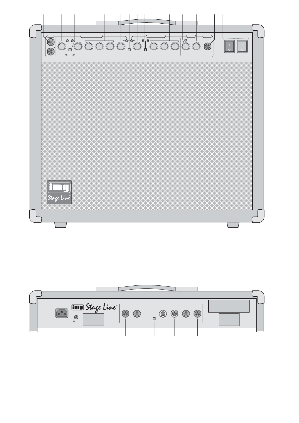
Bitte klappen Sie die Seite 3 heraus. Sie sehen
dann immer die beschriebenen Bedienelemente
und Anschlüsse.
1 Übersicht der Bedienelemente und
Anschlüsse
1.1 Frontseite
1 Eingangsbuchse INPUT HIGH (6,3-mm-Klinke)
Eingang mit hoher Verstärkung (High Gain) zum
Anschluss einer E-Gitarre, die Tonabnehmer
(Pickups) mit niedrigem Ausgangspegel besitzt
2 Eingangsbuchse INPUT LOW (6,3-mm-Klinke)
Eingang mit geringer Verstärkung (Low Gain)
zum Anschluss einer E-Gitarre, die Tonabnehmer (Pickups) mit hohem Ausgangspegel besitzt
3 Verstärkungsregler GAIN1 für den Overdrive
Channel zur Einstellung des Verzerrungsgrades
4 Gain-Umschalter GAIN SELECT für den Over-
drive Channel
Taste gedrückt: Regler GAIN2 (5) ist wirksam
nicht gedrückt: Regler GAIN1 (3) ist wirksam
5 Verstärkungsregler GAIN2 für den Overdrive
Channel zur Einstellung des Verzerrungsgrades
6 3fache Klangregelung (Equalizer) für den Over-
drive Channel
7 Lautstärkeregler LEVEL für das Gesamtsignal
des Overdrive Channel
8 Kanal-Umschalttaste CHANNEL SELECT
Taste gedrückt: Der Overdrive Channel ist akti-
viert.
nicht gedrückt: Der Normal Channel ist aktiviert.
9 Lautstärkeregler LEVEL für das Gesamtsignal
des Normal Channel
10 Modus-Umschalttaste MODE SELECT, um den
Pegel des Normal Channel zu beeinflussen:
Bei gedrückter T aste wird die Lautstärke um 6dB
angehoben (BOOST).
11 3fache Klangregelung (Equalizer) für den Nor-
mal Channel
12 Regler REVERB zum Einstellen des Hall-Effek-
tes
13 Lautstärkeregler VOLUME für das Gesamtsignal
14 6,3-mm-Klinkenbuchse PHONES zum Anschluss
eines Stereo-Kopfhörers (Impedanz min. 8Ω);
beim Anschluss schaltet der interne Lautsprecher ab
15 STANDBY-Schalter, sollte in den Spielpausen in
die Position „I“ gestellt werden, um die Lebensdauer der Röhren zu maximieren
16 Ein-/Ausschalter POWER
1.2 Rückseite
17 Netzbuchse zum Anschluss an 230V~/50 Hz
18 Halterung für die Netzsicherung;
eine durchgebrannte Sicherung nur durch eine
gleichen Typs ersetzen
19 6,3-mm-Klinkenbuchse zum Anschluss eines zu-
sätzlichen externen Lautsprechers (min. 8Ω);
der interne Lautsprecher wird nicht abgeschaltet
20 6,3-mm-Klinkenbuchse zum Anschluss eines zu-
sätzlichen externen Lautsprechers (min. 4Ω);
beim Anschluss schaltet der interne Lautsprecher ab
21 Umschalter LOOP LEVEL, um das eingeschleifte
Effekt-Signal (RETURN) im Pegel anzupassen
22 Effekt-Signal-Eingang RETURN
23 Effekt-Signal-Ausgang SEND
24 Fußschalter-Anschlussbuchse REVERB/BOOST
(6,3-mm-Stereo-Klinke) zum Ein-/Ausschalten
des Hall-Effektes und Aktivieren der Boost-Funktion im Normal Channel – siehe Kapitel 4,
Bedienschritt 2
25 Fußschalter-Anschlussbuchse CHANNEL/GAIN
(6,3-mm-Stereo-Klinke) zum Umschalten der
Kanäle (Normal/Overdrive Channel) und zum
Umschalten zwischen GAIN 1 / GAIN 2 im Overdrive Channel – siehe Kapitel 4, Bedienschritt 2
2 Hinweise für den sicheren Gebrauch
Dieses Gerät entspricht der Richtlinie für elektromagnetische Verträglichkeit 89/ 336/ EWG und der
Niederspannungsrichtlinie 73/23/EWG.
Beachten Sie auch unbedingt die folgenden Punkte:
●
Das Gerät ist nur zur Verwendung im Innenbereich geeignet. Schützen Sie es vor Tropf- und
Spritzwasser, hoher Luftfeuchtigkeit und Hitze
(zulässiger Einsatztemperaturbereich 0– 40°C).
●
Stellen Sie keine mit Flüssigkeit gefüllten Gefäße,
z.B. Trinkgläser, auf das Gerät.
●
Die im Gerät entstehende Wärme muss durch Luftzirkulation abgegeben werden. Decken Sie das
Lüftungsgitter auf der Geräterückseite niemals ab.
●
Stecken Sie nichts durch das Lüftungsgitter. Dies
kann zu einem elektrischen Schlag führen!
●
Nehmen Sie das Gerät nicht in Betrieb bzw. ziehen Sie sofort den Netzstecker aus der Steckdose:
1. wenn sichtbare Schäden am Gerät oder an der
Netzanschlussleitung vorhanden sind,
2. wenn nach einem Sturz oder Ähnlichem der
Verdacht auf einen Defekt besteht,
3. wenn Funktionsstörungen auftreten.
Lassen Sie das Gerät in jedem Fall in einer Fachwerkstatt reparieren.
●
Ziehen Sie den Netzstecker nie am Kabel aus der
Steckdose, fassen Sie immer am Stecker an.
●
Setzen Sie den Verstärker keinen starken Erschütterungen aus, damit die Röhren nicht beschädigt werden.
Achtung! Das Gerät wird mit lebensgefährlicher
Netzspannung (230 V~) versorgt. Nehmen Sie deshalb niemals selbst Eingriffe im Gerät vor. Durch unsachgemäßes Vorgehen besteht die Gefahr
eines elektrischen Schlages. Außerdem
erlischt beim Öffnen des Gerätes jeglicher Garantieanspruch.
Please unfold page 3. Then you can always see
the operating elements and connections described.
1 Elements and Connections
1.1 Front panel
1 Input jack INPUT HIGH (6.3 mm jack)
input with high gain for connecting an electric
guitar equipped with pickups of low output level
2 Input jack INPUT LOW (6.3 mm jack)
input with low gain for connecting an electric guitar equipped with pickups of high output level
3 Control GAIN1 for the overdrive channel for
adjusting the distortion rate
4 Selector button GAIN SELECT for the overdrive
channel
button pressed: control GAIN 2 (5) is effective
not pressed: control GAIN1 (3) is effective
5 Control GAIN2 for the overdrive channel for ad-
justing the distortion rate
6 3-way equalizer for the overdrive channel
7 Volume control LEVEL for the total signal of the
overdrive channel
8 Selector button CHANNEL SELECT
button pressed: the overdrive channel is acti-
vated.
not pressed: the normal channel is activated.
9 Volume control LEVEL for the total signal of the
normal channel
10 Selector button MODE SELECT to influence the
level of the normal channel:
with the button pressed, the volume is boosted
by 6dB (BOOST).
11 3-way equalizer for the normal channel
12 Control REVERB for adjusting the reverb effect
13 Control VOLUME for the total signal
14 6.3mm jack PHONES for connecting stereo
headphones (impedance min. 8 Ω); when connecting, the internal speaker is switched off
15 Switch STANDBY, should be set to position “I”
during music intervals to maximize the lifetime of
the tubes
16 POWER switch
1.2 Rear panel
17 Mains jack for connection to 230V~/50Hz
18 Support for the mains fuse; only replace a blown
fuse by one of the same type
19 6.3mm jack for connecting an additional external
speaker (min. 8Ω);
the internal speaker is not switched off
20 6.3mm jack for connecting an additional external
speaker (min. 4Ω);
when connecting, the internal speaker is
switched off
21 Selector button LOOP LEVEL to match the level
of the inserted effect signal (RETURN)
22 Effect signal input RETURN
23 Effect signal output SEND
24 Jack REVERB BOOST (6.3mm stereo jack) for
connecting a foot switch for switching on/off the
reverb effect and for activating the boost function
in the normal channel – see chapter 4, operating
step 2
25 Jack CHANNEL /GAIN (6.3 mm stereo jack) for
connecting a foot switch for switching the channels (normal/overdrive channel) and for switching
between GAIN 1/ GAIN 2 in the overdrive channel – see chapter 4, operating step 2
2 Safety Notes
This unit corresponds to the directive 89/336 / EEC
for electromagnetic compatibility and to the low voltage directive 73/23/EEC.
It is essential to observe the following items:
●
The unit is suitable for indoor use only. Protect it
against dripping water and splash water, high air
humidity, and heat (admissible ambient temperature range 0– 40°C).
●
Do not place any vessels filled with liquid, e. g.
drinking glasses, on the unit.
●
The heat being generated in the unit has to be
removed via air circulation. Therefore, the air vents
at the rear side of the unit must not be covered.
●
Do not insert anything into the air vents. This
could result in an electric shock!
●
Do not set the unit into operation, and immediately
disconnect the mains plug from the mains socket if
1. there is visible damage to the unit or to the
mains cable,
2. a defect might have occurred after a drop or
similar accident,
3. there are malfunctions.
The unit must in any case be repaired by skilled
personnel.
●
Never pull the mains cable to disconnect the
mains plug from the mains socket, always seize
the plug!
●
Never expose the amplifier to intensive vibrations
so that the tubes will not be damaged.
●
For cleaning only use a dry, soft cloth, by no
means chemicals or water.
●
No guarantee claims for the unit and no liability for
any resulting personal damage or material
damage will be accepted if the unit is used for pur-
Attention!
The unit is supplied with hazardous mains
voltage (230V~). Leave servicing to
skilled personnel only. Inexpert handling
may cause an electric shock hazard.
Furthermore, any guarantee claim will
expire if the unit has been opened.
4
GB
D
A
CH
●
Verwenden Sie für die Reinigung nur ein trockenes,
weiches Tuch, niemals W asser oder Chemikalien.
●
Wird das Gerät zweckentfremdet, nicht richtig angeschlossen, falsch bedient oder nicht fachgerecht
repariert, kann keine Haftung für daraus resultierende Sach- oder Personenschäden und keine
Garantie für das Gerät übernommen werden.
●
Soll das Gerät endgültig aus dem Betrieb genommen werden, übergeben Sie es zur umweltgerechten Entsorgung einem örtlichen Recyclingbetrieb.
3 Einsatzmöglichkeiten
und Ausstattung
Der GAT-1250R ist ein leistungsstarker Gitarrenverstärker (50W) in Röhrentechnologie für den Einsatz
auf der Bühne. Die zwei umschaltbaren Kanäle bieten dem Musiker die Möglichkeit, zwischen verzerrtem Sound (Overdrive Channel) und unverzerrtem
Sound (Normal Channel) zu wählen. Der Normal
Channel und der Overdrive Channel verfügen über
eine 3fache Klangregelung.
Über zwei unabhängige Gainregler im Overdrive
Channel lassen sich unterschiedliche Verzerrersounds einstellen. Der Normal Channel verfügt über
eine Boost-Möglichkeit, um den Pegel bei Bedarf
anzuheben.
Der Verstärker besitzt eine Hall-Spirale. Die
Zumischung des Hall-Effektes ist für beide Kanäle
möglich.
4 Anschlüsse herstellen
Alle Anschlüsse dürfen nur bei ausgeschaltetem
Gitarrenverstärker vorgenommen werden.
1) Die E-Gitarre an die Eingangsbuchse INPUT
HIGH (1) bzw. INPUTLOW (2) anschließen.
2) Soll die Kanalumschaltung und die Gain-Umschaltung für den Overdrive Channel über einen
Fußschalter erfolgen, diesen an die Buchse
CHANNEL/GAIN (25) anschließen. Um über
einen Fußschalter den Hall-Effekt ein- und auszuschalten sowie die Pegelumschaltung für den
Normal Channel vornehmen zu können, diesen
an die Buchse REVERB/BOOST (24) anschließen.
Je Anschlussbuchse wird ein Doppelfußschal-
ter benötigt, z.B. FS-202 von „img Stage Line“.
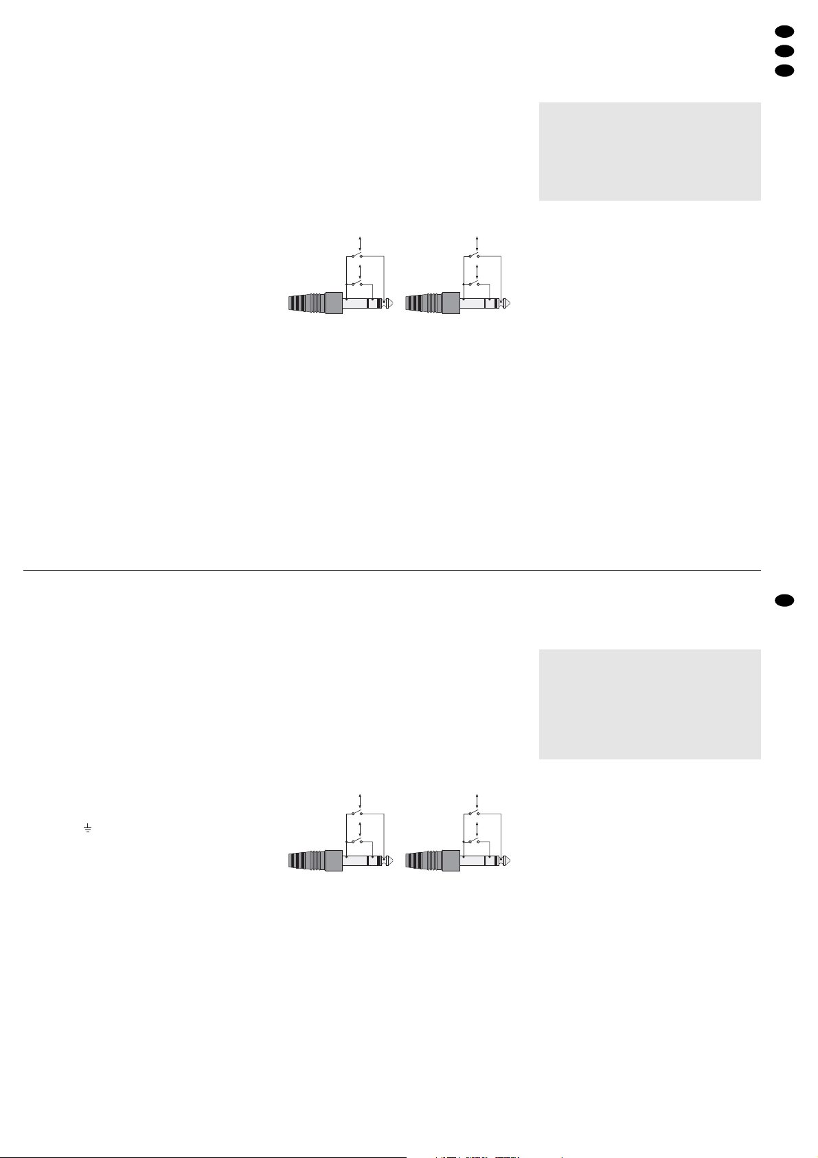
REVERB/ BOOST, Buchse (24) CHANNEL /GAIN, Buchse (25)
3) Ein externes Effektgerät lässt sich über die Buchsen SEND (23) und RETURN (22) einschleifen
(SEND mit dem Eingang und RETURN mit dem
Ausgang des externen Effektgerätes verbinden).
Eine eventuell erforderliche Pegelanpassung für
das Return-Signal kann mit dem Schalter LOOP
LEVEL (21) vorgenommen werden.
4) Ein externer 8-Ω-Lautsprecher lässt sich an die
Buchse EXTERNAL SPEAKER min. 8Ω (19) anschließen oder
ein externer 4-Ω-Lautsprecher an die Buchse
EXTERNAL SPEAKER min. 4Ω (20).
Die erforderliche Mindestimpedanz unbedingt
beachten, um den Verstärker nicht zu überlasten.
Bei Anschluss eines externen Lautsprechers an
die Buchse (19) wird der interne Lautsprecher
parallel betrieben, während die Verwendung der
Buchse (20) zur Abschaltung des internen Lautsprechers führt.
5) Ein Kopfhörer (Impedanz ≥ 8Ω) kann an die
Buchse PHONES (14) angeschlossen werden.
Bei Anschluss des Kopfhörers wird der Lautsprecher abgeschaltet.
6) Zum Schluss das beiliegende Netzkabel zuerst in
die Netzbuchse (17) und dann in eine Steckdose
(230V~/50Hz) stecken.
5 Bedienung
1) Vor dem Einschalten sollte der Lautstärkeregler
VOLUME (13) auf Minimum gestellt werden, um
starke Einschaltgeräusche zu vermeiden. Dann
den Gitarrenverstärker mit dem Schalter POWER
(16) einschalten.
Falls der Standby-Modus eingeschaltet ist
(siehe Kap. 5.4), den Schalter STANDBY (15) in
die Position „0“ stellen, sonst ist der Verstärker
stumm geschaltet.
2) Zuerst den gewünschten Kanal mit der KanalUmschalttaste CHANNEL SELECT (8) anwählen
bzw. mit einem an der Buchse CHANNEL/ GAIN
(25) angeschlossenen Fußschalter (der Fußschalter ist der Bedienung am Gerät übergeordnet):
Bei nicht gedrückter Umschalttaste ist der Normal Channel (unverzerrter Sound) angewählt.
Die grüne LED rechts oberhalb der Umschalttaste leuchtet.
Bei gedrückter Umschalttaste ist der Overdrive
Channel (verzerrter Sound) angewählt. Die rote
LED links oberhalb der Umschalttaste leuchtet.
Vorsicht:
Stellen Sie bei Verwendung eines Kopfhörers die
Lautstärke nie sehr hoch ein. Hohe Lautstärken
können auf Dauer das Gehör schädigen! Das
menschliche Ohr gewöhnt sich an große Lautstärken und empfindet sie nach einiger Zeit als
nicht mehr so hoch. Darum eine hohe Lautstärke
nach der Gewöhnung nicht weiter erhöhen.
poses other than originally intended, if it is not correctly connected, operated, or not repaired in an
expert way.
●
If the unit is to be put out of operation definitively,
take it to a local recycling plant for disposal which
is not harmful to the environment.
●
Important for U.K. Customers!
The wires in the mains lead of the power supply unit
are coloured in accordance with the following code:
green/yellow = earth
blue = neutral
brown = live
As the colours of the wires in the mains lead of this
appliance may not correspond with the coloured
markings identifying the terminals in your plug,
proceed as follows:
1. The wire which is coloured green and yellow
must be connected to the terminal in the plug
which is marked with the letter E or by the earth
symbol , or coloured green or green and
yellow.
2. The wire which is coloured blue must be connected to the terminal which is marked with the
letter N or coloured black.
3. The wire which is coloured brown must be connected to the terminal which is marked with the
letter L or coloured red.
Warning
-
This appliance must be earthed.
3 Applications and Features
The GAT-1250R is a powerful guitar amplifier (50 W)
in tube technology for stage applications. The two
switchable channels allow the musician to select
between distorted sound (overdrive channel) and
undistorted sound (normal channel). The normal
channel and the overdrive channel are provided with
a 3-way equalizer.
Via two independent gain controls in the overdrive channel it is possible to adjust different distortion sounds. The normal channel is provided with a
boost facility to boost the level, if required.
The amplifier is equipped with a reverb spring. It
is possible to add the reverb effect to both channels.
4 Making the Connections
All connections must only be made with the guitar
amplifier switched off.
1) Connect the electric guitar to the input jack
INPUT HIGH (1) or INPUT LOW (2).
2) To make the channel switching and the gain
switching for the overdrive channel via a foot
switch, connect it to the jack CHANNEL/ GAIN
(25). To be able to switch on/ off the reverb effect
and to make the level switching for the normal
channel via a foot switch, connect it to the jack
REVERB/ BOOST (24).
For each connection jack a dual foot switch is
required, e.g. FS-202 from “img Stage Line”.
REVERB/ BOOST, jack (24) CHANNEL/ GAIN, jack (25)
3) An external effect unit can be inserted via the
jacks SEND (23) and RETURN (22) [connect
SEND to the input and RETURN to the output of
the external effect unit]. If required, the level for
the return signal can be matched with the switch
LOOP LEVEL (21).
4) It is possible to connect an external 8 Ω speaker
to the jack EXTERNAL SPEAKER min. 8 Ω (19)
or
an external 4Ω speaker to the jack EXTERNAL
SPEAKER min. 4Ω (20).
Observe in any case the required minimum
impedance to avoid overload of the amplifier.
When connecting an external speaker to the jack
(19), the internal speaker will be operated in
parallel, when using the jack (20) the internal
speaker will be switched off.
5) Headphones (impedance ≥ 8Ω) can be connected to the jack PHONES (14). When connecting the headphones, the speaker will be switched
off.
6) Finally connect the supplied mains cable to the
mains jack (17) first and then to a socket
(230V~/50Hz).
5 Operation
1) Prior to switching on, the control VOLUME (13)
should be set to minimum to avoid strong inrush
noise. Then switch on the guitar amplifier with the
POWER switch (16).
If the standby mode is switched on (see chapter 5.4), set the switch STANDBY(15) to position
“0”, otherwise the amplifier will be muted.
2) First select the desired channel with the button
CHANNEL SELECT (8) or with a foot switch
connected to the jack CHANNEL/GAIN (25) [the
foot switch takes priority over the operation at the
unit]:
If the selector button is not pressed, the normal
channel (undistorted sound) is selected. The
green LED on the right above the selector button
lights up.
If the selector button is pressed, the overdrive
channel (distorted sound) is selected. The red
LED on the left above the selector button lights
up.
Caution:
When using headphones, do not adjust the
volume very high. Permanent high volumes may
damage your hearing! The human ear gets
accustomed to high volumes which do not seem
to be that high any more after some time. Therefore, do not further increase a high volume
which has once been adjusted after getting
used to it.
5
GB
D
A
CH
Reverb Off
Reverb On
Clean
Boost
Normal
Overdrive
Gain2
Gain1
Reverb Off
Reverb On
Clean
Boost
Normal
Overdrive
Gain2
Gain1

5.1 Normal Channel (unverzerrter Sound)
1) Zur optimalen Ausregelung des Klanges zunächst
die Lautstärkeregler LEVEL (9) und VOLUME
(13) auf mittlere Lautstärke einstellen.
2) Mit den drei Klangreglern (11) das Klangbild einstellen: Die Tiefen (BASS), Mitten (MIDDLE) und
Höhen (TREBLE) lassen sich bis zu 10 dB anheben.
3) Dann mit dem Lautstärkeregler LEVEL (9) die
gewünschte Lautstärke wählen.
Mit dem Regler VOLUME (13) kann die Lautstärke für den Overdrive Channel und den Normal Channel gemeinsam erhöht oder verringert
werden, während mit den Reglern LEVEL (7 und
9) im jeweiligen Kanal die Kanallautstärke eingestellt wird.
4) Wird während des Spielens ein erhöhter Ausgangspegel gewünscht (+6dB), um sich im
Arrangement von den anderen Instrumenten
akustisch abzuheben, so kann mit dem Schalter
MODE SELECT (10) auf BOOST umgeschaltet
werden. Die zugehörige rote LED leuchtet auf. Je
nach gewählter Kanal-/ Master-Lautstärke kann
der Sound dann schon leicht angezerrt sein, obwohl der Normal Channel noch angewählt ist.
Ein erneutes Drücken des Schalters (10)
bewirkt die Rückkehr in die CLEAN-Betriebsart
und lässt den Lautstärkepegel wieder auf den
vorherigen Wert absinken. Optisch wird der
CLEAN-Modus durch eine grüne LED gekennzeichnet.
Die Umschaltung BOOST/CLEAN kann auch
mit einem an der Buchse REVERB/BOOST (24)
angeschlossenen Fußschalter erfolgen.
5.2 Overdrive Channel (verzerrter Sound)
1) Zur optimalen Ausregelung des Klanges zunächst
die Lautstärkeregler LEVEL (7) und VOLUME
(13) auf mittlere Lautstärke einstellen.
2) Mit den Verstärkungsreglern GAIN1 (3) und
GAIN2 (5) wird der Grad der Übersteuerung des
Eingangssignals und damit der Verzerrungsgrad
eingestellt. Den jeweiligen Gainregler mit der
Taste GAIN SELECT (4) anwählen und den Regler je nach gewünschter Verzerrung aufdrehen.
GAIN2 ist ausgewählt, wenn die Taste GAIN
SELECT gedrückt wird. Die rote LED rechts
oberhalb der Taste leuchtet dann auf.
Die Umschaltung GAIN 1 /GAIN 2 kann auch
mit einem an der Buchse CHANNEL/GAIN (25)
angeschlossenen Fußschalter erfolgen.
3) Die drei Klangregler (6) ermöglichen eine von
den Klangreglern des Normal Channel unabhängige Sound-Einstellung für den Overdrive Channel.
4) Mit dem Lautstärkeregler LEVEL (7) die gewünschte Lautstärke einstellen.
Mit dem Regler VOLUME (13) kann die Lautstärke für den Overdrive Channel und den Normal Channel gemeinsam erhöht oder verringert
werden, während mit den Reglern LEVEL (7 und
9) im jeweiligen Kanal die Kanallautstärke eingestellt wird.
5.3 Zumischung des Hall-Effektes
Das Zumischen des Hall-Effektes ist für beide
Kanäle möglich. Mit dem Regler REVERB (12) den
gewünschten Hall-Anteil einstellen. Steht der Regler
auf Minimum, wird dem Signal kein Hall zugemischt.
Je weiter der Regler aufgedreht wird, desto stärker
ist der Hall-Anteil.
Mit einem an der Buchse REVERB/BOOST (24)
angeschlossenen Fußschalter kann der eingestellte
Hall-Effekt ein- und ausgeschaltet werden.
5.4 Standby-Modus
In den Spielpausen den Verstärker möglichst immer
mit dem Schalter STANDBY (15) in den Bereitschaftsmodus schalten (Position „I“). Die Röhren
werden dadurch geschont und ihre Lebensdauer
verlängert. Im Bereitschaftsmodus ist der Verstärker
stumm geschaltet. Vor dem Weiterspielen mit dem
Schalter STANDBYwieder auf Normalbetrieb schalten (Position „0“).
6Tipps und Tricks
1. Sollten während des Spielens ungewollte Feedbacks (Rückkopplung, Pfeifton aus dem Laut-
sprecher) auftreten, so können folgende Empfehlungen Abhilfe schaffen:
☞
Den Abstand zwischen der Gitarre und dem
Verstärker erhöhen.
☞
Die Position der Gitarre zum Verstärker verändern.
☞
Die Lautstärke [Regler LEVEL (7 und 9),
Regler VOLUME (13)] bzw. die Verstärkung
[Regler GAIN (3 und 5)] verringern.
☞
Den LOW-Eingang (2) benutzen.
2. Ein Brummen aus den Lautsprechern lässt sich
durch folgende Maßnahmen verringern oder beseitigen:
☞
Den Abstand zwischen der Gitarre und dem
Verstärker erhöhen.
☞
Die Position der Gitarre zum Verstärker verändern.
☞
Das Gitarrenanschlusskabel austauschen.
☞
Die Röhren austauschen.
☞
Humbucker-Tonabnehmer (brummunterdrückende Tonabnehmer) verwenden.
☞
Die Tonabnehmer-/Mechanikausfräsungen
der Gitarre abschirmen.
3. Plötzliche Scheppergeräusche der Hallspirale
(bei aufgedrehtem REVERB-Regler) lassen sich
vermeiden, wenn der Verstärker auf einem sehr
festen Untergrund oder zur Entkopplung auf
einem sehr weichen Untergrund (Schaumgummi) platziert wird. Die Ursache für diese Geräusche sind Trittschallübertragungen über den
Fußboden zum Verstärkergehäuse.
4. In Spielpausen den Verstärker nie komplett aus-
schalten, sondern immer den Standby-Schalter
(15) benutzen. Die Röhren werden geschont und
der Verstärker ist wesentlich schneller wieder
spielbereit, da die Röhren nicht mehr aufgeheizt
werden müssen.
5.1 Normal channel (undistorted sound)
1) For optimum level control of the sound first set
the volume controls LEVEL (9) and VOLUME
(13) to medium volume.
2) Adjust the sound with the three equalizer controls
(11): it is possible to boost the BASS, MIDDLE,
and TREBLE frequencies up to 10dB.
3) Then select the desired volume with the volume
control LEVEL (9).
With the control VOLUME (13) the volume for
the overdrive channel and the normal channel
can be boosted or attenuated together while the
channel volume of the respective channel is adjusted with the controls LEVEL (7 and 9).
4) If an elevated output level (+6 dB) is desired while
playing to distinguish the guitar from the other
musical instruments of the arrangement, it is possible to switch to BOOST with the button MODE
SELECT (10). The corresponding red LED lights
up. Depending on the selected channel/ master
volume the sound may be slightly distorted although the normal channel is still selected.
Press the button (10) again to return to the
operating mode CLEAN and make the volume
level fall down to its previous value again. The
CLEAN mode is displayed by a green LED.
The selection of BOOST/CLEAN can also be
made with a foot switch connected to the jack
REVERB/BOOST (24).
5.2 Overdrive channel (distorted sound)
1) For optimum level control of the sound first set
the volume controls LEVEL (7) and VOLUME
(13) to average volume.
2) With the controls GAIN 1 (3) and GAIN 2 (5) the
overdrive rate of the input signal is adjusted and
thus the distortion rate. Select the corresponding
gain control with the button GAIN SELECT (4)
and turn up the control according to the desired
distortion. GAIN2 is selected if the button GAIN
SELECT is pressed. Then the red LED on the
right above the button lights up.
The selection GAIN1/GAIN2 can also be
made with a foot switch connected to the jack
CHANNEL/GAIN (25).
3) The three equalizer controls (6) allow a sound
adjustment for the overdrive channel independent of the equalizer controls of the normal channel.
4) With the volume control LEVEL (7) adjust the
desired volume.
With the control VOLUME (13) the volume for
the overdrive channel and the normal channel
can be boosted or attenuated together while the
channel volume of the respective channel is adjusted with the controls LEVEL (7 and 9).
5.3 Adding the reverb effect
It is possible to add the reverb effect to both channels. Adjust the desired reverb part with the control
REVERB (12). If the control is in minimum position,
no reverb is added to the signal. The more the control is turned up, the more powerful the reverb part.
The adjusted reverb effect can be switched
on/off with a foot switch connected to the jack
REVERB/BOOST (24).
5.4 Standby mode
During music intervals, if possible, always set the
amplifier to the standby mode (position “I”) with the
switch STANDBY (15). Thus, the tubes are saved
and their service life will be extended. In the standby
mode the amplifier is muted. Prior to continuing to
play, set the amplifier to normal mode again (position “0”) with the switch STANDBY.
6Tips and Tricks
1. If unwanted feedback (howlback, whistling
sound from the speaker) should occur while playing, the following recommendations can be useful:
☞
Increase the distance between the guitar and
the amplifier.
☞
Change the position of the guitar towards the
amplifier.
☞
Attenuate the volume [controls LEVEL(7 and
9), control VOLUME (13)] or the gain [controls GAIN (3 and 5)].
☞
Use the LOW input (2).
2. Humming from the speakers can be reduced or
eliminated with the following measures:
☞
Increase the distance between the guitar and
the amplifier.
☞
Change the position of the guitar towards the
amplifier.
☞
Replace the connection cable of the guitar.
☞
Replace the tubes.
☞
Use humbucker pickups (pickups suppressing humming).
☞
Screen the recesses for pickups and mechanics of the guitar.
3. Sudden rattling noise of the reverb spring
(with the REVERB control turned up) can be
avoided if the amplifier is placed on a very firm
ground or, for decoupling, on a very soft ground
(foam rubber). The reason for this is a transmission of rumble noise via the floor to the amplifier
housing.
4. During music intervals never completely switch
off the amplifier but always use the standby
switch (15). The tubes are saved and the amplifier is much earlier ready again for playing as the
tubes do not have to be heated up any more.
6
GB
D
A
CH
 Loading...