

IMG STAGE LINE DMX-1440 Instruction Manual
BEDIENUNGSANLEITUNG • INSTRUCTION MANUAL • MODE D’EMPLOI
ISTRUZIONI PER L’USO • GEBRUIKSAANWIJZING • MANUAL DE INSTRUCCIONES
SIKKERHEDSOPLYSNINGER • SÄKERHETSFÖRESKRIFTER • TURVALLISUUDESTA
DMX-LICHTSTEUERPULT
FÜR 144 DMX-ADRESSEN
DMX CONTROLLER FOR 144 ADDRESSES
CONTRÔLEUR DMX POUR 144 ADRESSES DMX
UNITÀ DI COMANDO LUCE DMX PER 144 INDIRIZZI DMX
DMX-1440 Best.-Nr. 38.1980

2
wwwwww..iimmggssttaaggeelliinnee..ccoomm
Bevor Sie einschalten ...
Wir wünschen Ihnen viel Spaß mit Ihrem neuen Gerät von
„img Stage Line“. Dabei soll Ihnen diese Bedienungsanleitung helfen, alle Funktionsmöglichkeiten kennen zu lernen. Die Beachtung der Anleitung vermeidet außerdem
Fehlbedienungen und schützt Sie und Ihr Gerät vor eventuellen Schäden durch unsachgemäßen Gebrauch.
Den deutschen Text finden Sie auf den Seiten 4– 19.
Before you switch on ...
We wish you much pleasure with your new “img Stage
Line” unit. With these operating instructions you will be
able to get to know all functions of the unit. By following
these instructions false operations will be avoided, and
possible damage to yourself and your unit due to improper use will be prevented.
You will find the English text on the pages 4–19.
D
A
CH
GB
Inden De tænder for apparatet ...
Vi ønsker Dem god fornøjelse med Deres nye “img
Stage Line” apparat. Læs oplysningerne for en sikker
brug af apparatet før ibrugtagning. Følg sikkerhedsoplysningerne for at undgå forkert betjening og for at beskytte Dem og Deres apparat mod skade på grund af forkert brug.
Sikkerhedsoplysningerne finder De på side 52.
Voordat u inschakelt ...
Wij wensen u veel plezier met uw nieuw toestel van “img
Stage Line”. Met behulp van bijgaande gebruiksaanwijzing zal u alle functiemogelijkheden leren kennen.
Door deze instructies op te volgen zal een slechte werking vermeden worden, en zal een eventueel letsel aan
uzelf en schade aan uw toestel tengevolge van onzorgvuldig gebruik worden voorkomen.
U vindt de nederlandstalige tekst op de pagina’s 36– 51.
DK
B
NL
Antes de cualquier instalación ...
Tenemos de agradecerle el haber adquirido un aparato
“img Stage Line” y le deseamos un agradable uso. Este
manual quiere ayudarle a conocer las multiples facetas
de este aparato. La observación de las instrucciones
evita operaciones erróneas y protege Vd. y vuestro aparato contra todo daño posible por cualquier uso inadecuado.
La versión española se encuentra en las páginas 36– 51.
Förskrift
Vi önskar dig mycket nöje med din nya enhet från “img
Stage Line”. Läs gärna säkerhetsinstruktionerna innan
du använder enheten. Genom att följa säkerhetsinstruktionerna kan många problem undvikas, vilket annars kan
skada enheten.
Du finner säkerhetsinstruktionerna på sidan 52.
E
S
Ennen virran kytkemistä ...
Toivomme, että uusi “img Stage Line”-laitteesi tuo sinulle
paljon iloa ja hyötyä. Ole hyvä ja lue käyttöohjeet ennen
laitteen käyttöönottoa. Luettuasi käyttöohjeet voit käyttää laitetta turvallisesti ja vältyt laitteen väärinkäytöltä.
Käyttöohjeet löydät sivulta 52.
FIN
Avant toute mise en service ...
Nous vous remercions d’avoir choisi un appareil “img
Stage Line” et vous souhaitons beaucoup de plaisir à
l’utiliser. Cette notice a pour objectif de vous aider à
mieux connaître les multiples facettes de l’appareil. En
outre, en respectant les conseils donnés, vous éviterez
toute mauvaise manipulation de sorte que vous-même et
votre appareil soient protégés de tout dommage.
La version française se trouve pages 20– 35.
Prima di accendere ...
Vi auguriamo buon divertimento con il Vostro nuovo
apparecchio “img Stage Line”. Le istruzioni per l’uso Vi
possono aiutare a conoscere tutte le possibili funzioni. E
rispettando quanto spiegato nelle istruzioni, evitate di
commettere degli errori, e così proteggete Voi stessi, ma
anche l’apparecchio, da eventuali rischi per uso improprio.
Il testo italiano lo potete trovare alle pagine 20– 35.
F
B
CH
I
3
MIN MAXMIN MAN
MAX
POWER
MICHOLD
C.F. TIME AUDIO SENS.
TAP SPEED DELETE INSERT
ESC/ SETUP SEQUENCE
STORE/PRG BANK/ AUDIO FULL ON
BLACKOUT
RUN
PRG
12 78
MANUAL
CROSSFADE
MASTER
LEVEL
HOLD/
CROSSFADE
CTRLCHANNEL PAGE SCENE / NUMERICAL INPUT
1234567890-- /NO +/YES
1..12
13..24
25..36
37..48
49..60
61..72
73..84
85..96
FL. CH.
SH.VAL.
UNIVERSAL DMX CONTROLLER
FL. GRP.
123456789101112
DMX-1440
STICK CTRL
MOTION
CONTROL
STICK CTRL
100%
50%
0%
FLASH MODE
STICK CONTROL ASSIGN
MIN MAX
0.1
0.5
1
235
7
10
SEQUENCER SPEED
M
I
N
U
T
E
S
/
S
T
E
P
TAP SPEED DELETE INSERT
SEQUENCE
STORE/PRG BANK/ AUDIO FULL ON
BLACKOUT
RUN
PRG
ESC/ SETUP
➀
➁
DMX OUT AUDIO IN
0.1...2V
230V~ /50Hz
1: GND
2: SIGNAL–
3: SIGNAL+
4: N.C.
5: N.C.
531
42
231
DMX-1440
WWW.IMGSTAGELINE.COM
PUSH PUSH
123456789
10 11 12 13 14 15 16 17 18 19
20
21
22
23
24
25
26
27
28
29
30 31 32
SR-103DMX
SR-105DMX
MIN MAXMIN MAN
MAX
POWER
MICHOLD
C.F. TIME AUDIO SENS.
TAP SPEED DELETE INSERT
ESC/SETUP SEQUENCE
STORE/PRG BANK/AUDIO FULL ON
BLACKOUT
RUN
PRG
12 78
MANUAL
CROSSFADE
MASTER
LEVEL
HOLD/
CROSSFADE
CTRLCHANNELPAGE SCENE / NUMERICAL INPUT
1234567890-- /NO +/YES
1..12
13..24
25..36
37..48
49..60
61..72
73..84
85..96
FL.CH.
SH.VAL.
UNIVERSAL DMX CONTROLLER
FL.GRP.
123456789101112
DMX-1440
STICK CTRL
MOTION
CONTROL
STICK CTRL
100%
50%
0%
FLASHMODE
STICK CONTROL ASSIGN
MIN MAX
0.1
0.5
1
235
7
10
SEQUENCER SPEED
M
I
N
U
T
E
S
/
S
T
E
P
PITCH
CONTROL
456789CFM
IR SENSOR
SEARCH
SCAN
CUE
+10 TIME
PITCH BENDSTART/PAUSE
TIMESTOP–
TRACK
OPEN / CLOSE
SGL
PITCH
—+
START
LOOP
EXIT
PROFESSIONAL CD MP3 PLAYER
PROG. 0 1 2 3
POWER
TOTAL TRACK
AUTO CUE SINGLE REMAIN
SR-103DMX
3 CHANNEL DMX SPLITTER / REPEATER
DMX IN
ISO 3ISO 2ISO 1
DMX OUT
AUDIO IN
CD Player
DMX OUT
DMX-1440
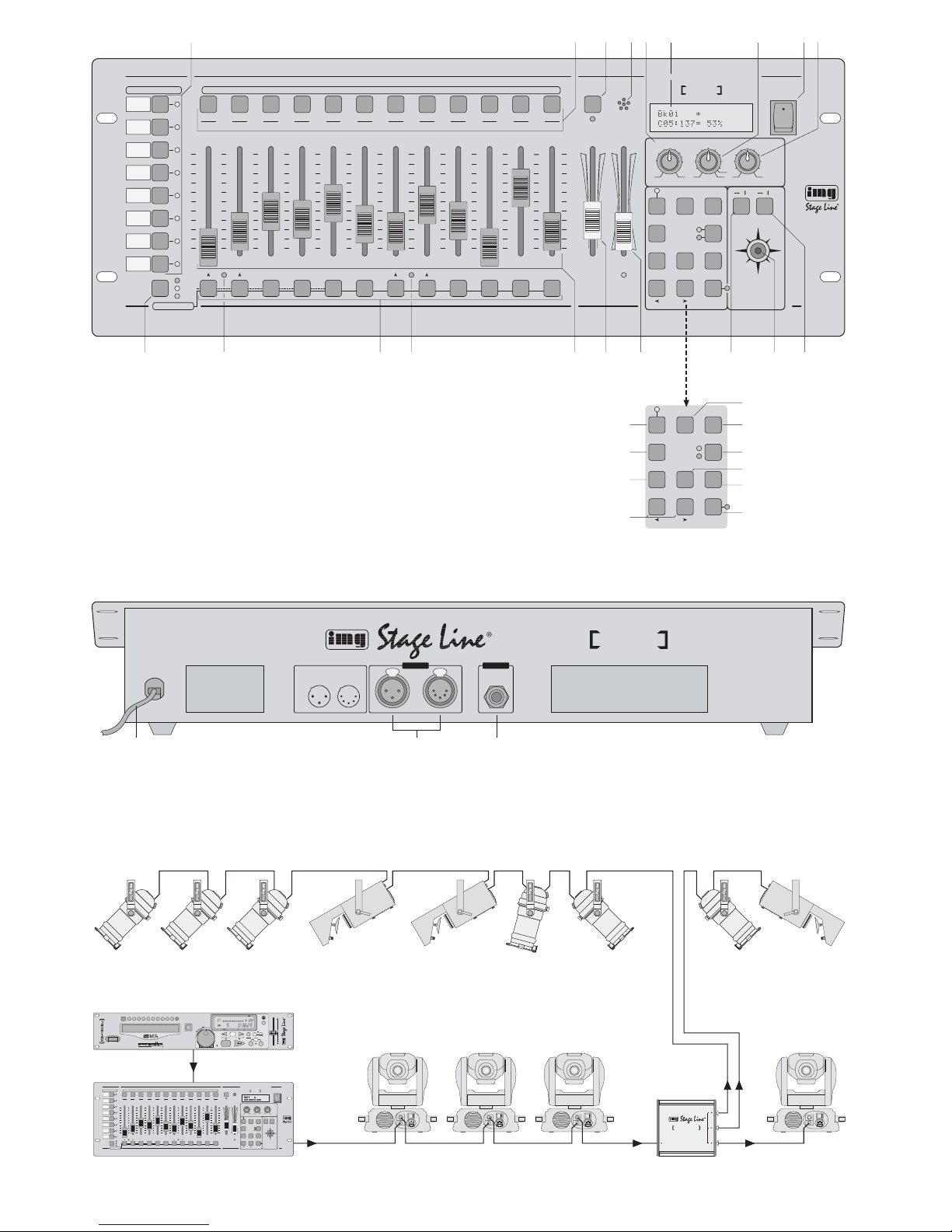
Anschlussbeispiel • Example for connection • Exemple de connexion • Esempio applicativo • Voorbeeld van aansluiting • Ejemplo de conexión
➂

Inhalt
1 Übersicht der Bedienelemente und
Anschlüsse . . . . . . . . . . . . . . . . . . . . . . . . . 4
1.1 Frontseite . . . . . . . . . . . . . . . . . . . . . . . . . . . 4
1.2 Rückseite . . . . . . . . . . . . . . . . . . . . . . . . . . .5
2 Hinweise für den sicheren Gebrauch . . . . 6
3 Einsatzmöglichkeiten und
Funktionseigenschaften . . . . . . . . . . . . . . 6
4 Inbetriebnahme . . . . . . . . . . . . . . . . . . . . . . 7
4.1 Gerät aufstellen . . . . . . . . . . . . . . . . . . . . . . 7
4.2 Geräte anschließen . . . . . . . . . . . . . . . . . . . 7
4.3 DMX-Startadressen der Lichteffektgeräte
einstellen . . . . . . . . . . . . . . . . . . . . . . . . . . . 7
4.4 Steuerkanäle konfigurieren . . . . . . . . . . . . . . 7
4.4.1 DMX-Adressen zuordnen (DMX-PATCH)
und Ausgabewerte invertieren . . . . . . . . . . 8
4.4.2 Optionen der Steuerkanäle festlegen . . . . 8
4.4.3 Zurücksetzen sämtlicher Adressen-
zuordnungen und Steuerkanaloptionen . . 9
5 Bedienung im Direkt-Modus . . . . . . . . . . . 9
5.1 Beleuchtungsszene einstellen . . . . . . . . . . . 9
5.2 Bedienung des Steuerhebels . . . . . . . . . . . . 9
5.3 Beleuchtungsszene mit dem Regler
MASTER LEVEL dimmen . . . . . . . . . . . . . . 10
5.4 Steuerkanäle auf den Maximalwert schalten
(max. Helligkeit) . . . . . . . . . . . . . . . . . . . . . 10
5.4.1 Flash-Gruppen nutzen . . . . . . . . . . . . . . 10
5.4.2 Alle Steuerkanäle auf den Maximalwert
schalten . . . . . . . . . . . . . . . . . . . . . . . . . . 11
5.5 Blackout-Funktion . . . . . . . . . . . . . . . . . . . . 11
5.6 Aktuelle Werte der Steuerkanäle anzeigen . 11
5.7 Ausgabewerte festhalten (Hold-Modus)
und zur nächsten Szene überblenden . . . . 11
5.7.1 Überblendzeit einstellen . . . . . . . . . . . . . 11
5.7.2 Überblenden mit dem Crossfader . . . . . .11
6 Szenenspeicher verwenden . . . . . . . . . . . 11
6.1 Speichern von Szenen . . . . . . . . . . . . . . . . 11
6.2 Gespeicherte Szenen aufrufen . . . . . . . . . . 12
6.2.1 Abbruch einer laufenden Überblendung . 12
6.2.2 Vormerken der übernächsten Szene . . . . 12
7 Szenensequenzen . . . . . . . . . . . . . . . . . . 13
7.1 Sequenzen neu programmieren
oder ändern . . . . . . . . . . . . . . . . . . . . . . . . 13
7.1.1 Sequenznummer wählen . . . . . . . . . . . . 13
7.1.2 Sequenz löschen und
neu programmieren . . . . . . . . . . . . . . . . . 13
7.1.3 Sequenzschritte anhängen oder ändern . 13
7.1.4 Sequenzschritte einfügen . . . . . . . . . . . . 14
7.1.5 Sequenzschritte löschen . . . . . . . . . . . . . 14
7.2 Szenensequenz starten . . . . . . . . . . . . . . . 14
7.2.1 Manuelle Szenenüberblendung
einer Sequenz . . . . . . . . . . . . . . . . . . . . . 15
7.2.2 Sequenzablauf unterbrechen . . . . . . . . . 15
7.2.3 Sequenzablauf beenden . . . . . . . . . . . . . 15
8 Kurzübersicht über die Bedienung . . . . . 16
9Technische Daten . . . . . . . . . . . . . . . . . . . 18
Übersicht der Konfigurationsmöglichkeiten . . . . 18
Tabelle zum Eintragen der Konfiguration . . . . . . 54
Tabelle zum Eintragen der gespeicherten Szenen 56
Bitte klappen Sie die Seite 3 heraus. Sie sehen
dann immer die beschriebenen Bedienelemente
und Anschlüsse.
1 Übersicht der Bedienelemente und
Anschlüsse
1.1 Frontseite
1 Tasten zum Anwählen von jeweils 12 Steuer-
kanälen (1– 12, 13–24, 25 –36, 37 –48, 49– 60,
61– 72, 73–84, 85 –96), um über die 12 Schieberegler (14) die Lichteffektgeräte zu steuern, die
den gewählten Kanälen zugewiesen wurden
Um mehrere Kanäle unterschiedlicher 12er-Kanalgruppen auf den gleichen Wert einzustellen,
die entsprechenden Tasten gleichzeitig drücken.
Die LEDs neben den Tasten zeigen die aktivierten Gruppen an.
2 Zifferntasten zum Aufrufen von gespeicherten
Szenen aus einer der 20 Speicherbanken (zur
Auswahl einer Speicherbank siehe Positionen
23 und 27)
Bei aufgerufenem Konfigurationsmenü dienen
die Tasten zur Eingabe; es ist dann die untere
Beschriftung zu beachten.
3 Taste HOLD zum Festhalten aller eingestellten
Ausgabewerte (Kap. 5.7)
Mit der T aste HOLD lässt sich eine laufende Über-
blendung abbrechen (Kap. 6.2.1) oder der Ablauf
einer Szenensequenz anhalten (Kap. 7.2.2).
4 Schallöffnung für das integrierte Mikrofon zum
musikgesteuerten Ablauf einer programmierten
Szenensequenz
5 Regler SEQUENCER SPEED für die Ablaufge-
schwindigkeit einer Szenensequenz
6 alphanumerisches Display
7 Regler C.F. TIME zum Einstellen der Überblend-
zeit zwischen zwei Szenen (0– 25,4s);
bei Rechtsanschlag (Position MAN) mit dem
Contents
1 Operating Elements and Connections . . . 4
1.1 Front panel . . . . . . . . . . . . . . . . . . . . . . . . . . 4
1.2 Rear panel . . . . . . . . . . . . . . . . . . . . . . . . . . 5
2 Safety Notes . . . . . . . . . . . . . . . . . . . . . . . . 6
3 Applications and Characteristics
of Functions . . . . . . . . . . . . . . . . . . . . . . . . 6
4 Setting into Operation . . . . . . . . . . . . . . . . 7
4.1 Setting up the unit . . . . . . . . . . . . . . . . . . . . . 7
4.2 Connecting the units . . . . . . . . . . . . . . . . . . . 7
4.3 Adjusting the DMX start addresses
of the light effect units . . . . . . . . . . . . . . . . . . 7
4.4 Configuring control channels . . . . . . . . . . . . 7
4.4.1 Assigning DMX addresses (DMX PATCH)
and inverting output values . . . . . . . . . . . .8
4.4.2 Defining the options of
the control channels . . . . . . . . . . . . . . . . . 8
4.4.3 Reset of all address assignments
and control channel options . . . . . . . . . . . 9
5 Operation in the Direct Mode . . . . . . . . . . 9
5.1 Adjusting an illumination scene . . . . . . . . . . 9
5.2 Operating the control lever . . . . . . . . . . . . . . 9
5.3 Dimming an illumination scene with
the fader MASTER LEVEL . . . . . . . . . . . . .10
5.4 Setting the control channels to the
maximum value (max. brightness) . . . . . . . 10
5.4.1 Using the flash groups . . . . . . . . . . . . . . 10
5.4.2 Setting all control channels to
the maximum value . . . . . . . . . . . . . . . . . 11
5.5 Blackout function . . . . . . . . . . . . . . . . . . . . . 11
5.6 Displaying current values of
the control channels . . . . . . . . . . . . . . . . . . 11
5.7 Holding the output values (hold mode) and
crossfading to the next scene . . . . . . . . . . . 11
5.7.1 Adjusting the crossfading time . . . . . . . . .11
5.7.2 Crossfading with the crossfader . . . . . . . 11
6 Using the Scene Memory . . . . . . . . . . . . . 11
6.1 Memorizing scenes . . . . . . . . . . . . . . . . . . . 11
6.2 Calling memorized scenes . . . . . . . . . . . . . 12
6.2.1 Interruption of a current crossfading . . . . 12
6.2.2 Noting down the next but one scene . . . . 12
7 Scene Sequences . . . . . . . . . . . . . . . . . . . 13
7.1 Reprogramming or changing scenes . . . . . 13
7.1.1 Selecting a sequence number . . . . . . . . . 13
7.1.2 Deleting and reprogramming a sequence . 13
7.1.3 Attaching or changing sequence steps . . 13
7.1.4 Inserting sequence steps . . . . . . . . . . . . 14
7.1.5 Deleting sequence steps . . . . . . . . . . . . . 14
7.2 Starting the scene sequence . . . . . . . . . . . 14
7.2.1 Manual scene crossfading of a sequence . 15
7.2.2 Interrupting the sequence run . . . . . . . . . 15
7.2.3 Stopping the sequence run . . . . . . . . . . . 15
8 Short Overview of the Operation . . . . . . 17
9 Specifications . . . . . . . . . . . . . . . . . . . . . . 18
Overview of the Configuration Possibilities . . . . . 18
Table to enter the configuration . . . . . . . . . . . . . 54
Table to enter the memorized scenes . . . . . . . . . 56
Please take out page 3. Then you can always see
the operating elements and connections described.
1 Operating Elements and Connections
1.1 Front panel
1 Buttons to select 12 control channels each
(1– 12, 13–24, 25 –36, 37 –48, 49– 60, 61– 72,
73– 84, 85–96) to control via the 12 sliding controls (14) the light effect units assigned to the selected channels
To adjust several channels of different 12-channel groups to the same value, press the corresponding buttons at the same time. The LEDs
next to the buttons show the activated groups.
2 Numerical keys to call memorized scenes from
one of the 20 memory banks (for the selection of
a memory bank, see items 23 and 27)
With the configuration menu called, the buttons
serve to make an entry; in this case pay attention
to the lower lettering.
3 Button HOLD to hold all adjusted output values
(chapter 5.7)
With the button HOLD it is possible to interrupt a
current crossfading (chapter 6.2.1) or to hold the
run of a scene sequence (chapter 7.2.2)
4 Sound aperture for the integrated microphone for
music-controlled run of a programmed scene
sequence
5 Control SEQUENCER SPEED for the running
speed of a scene sequence
6 Alphanumeric display
7 Control C.F. TIME to adjust the crossfading time
between two scenes (0– 25.4s);
with the control at the right stop (position MAN)
crossfade with the sliding control MANUAL
CROSSFADE (16)
8 POWER switch
4
GB
D
A
CH

Schieberegler MANUALCROSSFADE (16) überblenden
8 Ein-/Ausschalter POWER
9 Regler AUDIO SENS. zum Einstellen der An-
sprechschwelle beim musikgesteuerten Ablauf
einer Szenensequenz
10 Taste FLASH MODE zur Funktionsauswahl der
Flash-Tasten (12):
Grundeinstellung (rote LED FL.CH. leuchtet)
Beim Gedrückthalten einer Flash-Taste (12)
wird unabhängig vom Regler MASTER LEVEL
(15) der zugehörige Steuerkanal auf den Maximalwert 255 gestellt, wenn diese Funktion für
den entsprechenden Steuerkanal zugelassen
ist (Kap. 4.4.2). Damit lässt sich z.B. ein
Scheinwerfer auf max. Helligkeit schalten.
1.Tastendruck (gelbe LED FL.GRP. leuchtet)
Beim Gedrückthalten einer der fünf FlashTasten von links werden die zu einer FlashGruppe zusammengefassten Steuerkanäle
(Kap. 5.4.1) auf den Maximalwert geschaltet.
2.Tastendruck (grüne LED SH.VAL. leuchtet)
Durch Drücken einer Flash-Taste wird der
aktuelle DMX-Wert des zugehörigen Kanals
im Display angezeigt.
3.Tastendruck Grundeinstellung
11 Anzeige STICK CTRL für den 1. und 2. Steuer-
kanal jeder Kanalgruppe; leuchtet, wenn die
Taste STICK CONTROL ASSIGN 1/2 (17) gedrückt wurde. Die Kanäle 1 und 2 (bzw. 13 + 14;
25 + 26 … 85 + 86) lassen sich dann mit dem
Steuerhebel MOTION CONTROL(18) einstellen.
12 Flash-Tasten; Funktionen siehe Position 10
13 Anzeige STICK CTRL für den 7. und 8. Steuer-
kanal jeder Kanalgruppe; leuchtet, wenn die
Taste STICK CONTROL ASSIGN 7/8 (19) gedrückt wurde. Die Kanäle 7 und 8 (bzw. 19 + 20;
31 + 32 … 91 + 92) lassen sich dann mit dem
Steuerhebel MOTION CONTROL(18) einstellen.
14 Schieberegler zur Steuerung der angeschlosse-
nen Lichteffektgeräte
15 Regler MASTER LEVEL zum Dimmen der aktu-
ellen Szene
Alle Werte der Steuerkanäle, für die eine Beeinflussung durch den Regler MASTER LEVEL
zugelassen wurde (Kap. 4.4.2), lassen sich gemeinsam mit diesem Regler verringern.
16 Regler MANUAL CROSSFADE zum manuellen
Überblenden von einer zur anderen Szene; dazu
muss der Regler C.F. TIME (7) ganz nach rechts
gedreht werden (Position MAN), so dass die
grüne LED unterhalb des Reglers MANUAL
CROSSFADE leuchtet
17 Taste STICK CONTROLASSIGN 1/2
Bei betätigter Taste leuchtet die Anzeige STICK
CTRL (11) und der 1. und 2. Steuerkanal der
angewählten Kanalgruppe lassen sich mit dem
Steuerhebel MOTION CONTROL (18) einstellen.
18 Steuerhebel; Funktion siehe Tasten STICK
CONTROLASSIGN Positionen 17 und 19
19 Taste STICK CONTROLASSIGN 7/8
Bei betätigter Taste leuchtet die Anzeige STICK
CTRL (13) und der 7. und 8. Steuerkanal der
angewählten Kanalgruppe lassen sich mit dem
Steuerhebel MOTION CONTROL (18) einstellen.
20 Taste TAP SPEED; durch zweimaliges Drücken
kann die Ablaufgeschwindigkeit einer Szenensequenz eingestellt werden [alternativ zum Regler
SEQUENCER SPEED (5)]
21 Taste ESC /SETUP zum Aufrufen und Verlassen
des Konfigurationsmenüs
22 Taste STORE/PRG zum Speichern einer Szene
(Kap. 6.1) und zum Speichern einer Szenensequenz (Kap. 7.1)
23 Cursor-Tasten und zum Anwählen einer
Speicherbank; bei aufgerufenem Konfigurationsmenü zum Vor- und Zurückspringen auf die einzelnen Parameter und im Sequenzmodus zum
Anwählen einzelner Sequenzschritte
24 Taste DELETE, um alle Steuerkanäle auf den
Wert Null zu schalten (Kap. 5.1 und 6.1) und zum
Löschen einer Szenensequenz (Kap. 7.1.2) oder
einzelner Sequenzschritte (Kap. 7.1.5); jeweils
in Kombination mit der Taste STORE/PRG (22)
25 Taste INSERT zum Einfügen von Sequenzschrit-
ten in eine Szenensequenz (Kap. 7.1.4)
26 Taste SEQUENCE zum Ablauf, Beenden oder
Programmieren einer Szenensequenz
27 Taste BANK/AUDIO; nach dem Betätigen dieser
Taste kann die Banknummer zweistellig mit den
Zifferntasten (2) eingetippt werden; im Sequenzmodus dient die Taste zum Starten einer Szenensequenz, die musikgesteuert ablaufen soll
(Kap. 7.2)
28 Taste FULL ON, schaltet alle für diese Funktion
zugelassen Steuerkanäle (Kap. 4.4.2) auf den
Maximalwert
Damit lassen sich z.B. alle DMX-Geräte auf
maximale Helligkeit schalten, ohne dass andere
Funktionen wie Schwenken, Neigen, Farb- oder
Gobo-Wechsel beeinflusst werden.
29 Taste BLACKOUT, schaltet alle für diese Funk-
tion zugelassen Steuerkanäle (Kap. 4.4.2) auf
den Wert Null
Damit lassen sich z.B. alle DMX-Geräte dunkel
schalten.
1.2 Rückseite
30 Netzkabel zum Anschluss an eine Steckdose
(230V~/50Hz)
31 DMX-Signal-Ausgänge
1 = Masse, 2 = DMX
-
, 3 = DMX+, 4 und 5 = frei
Je nach vorhandenem DMX-Eingang am ersten
Lichteffektgerät die 3-polige oder die 5-polige
XLR-Buchse an das Lichteffektgerät anschließen; den Ausgang des ersten Lichteffektgerätes
mit dem Eingang des nächsten Gerätes verbinden usw.
32 Stereo-Audioeingang zum Anschluss eines Audio-
gerätes mit Line-Ausgang (0,1– 2V), um den Ablauf einer Szenensequenz im Takt der Musik zu
steuern; beim Anschluss der Buchse wird das
interne Mikrofon (4) abgeschaltet.
9 Control AUDIO SENS. to adjust the threshold in
case of music-controlled run of a scene sequence
10 Button FLASH MODE to select the functions of
the flash buttons (12):
Basic setting (red LED FL.CH. lights up)
When keeping a flash button (12) pressed,
independent of fader MASTER LEVEL (15)
the corresponding control channel is set to
the maximum value 255 if this function has
been admitted for the corresponding control
channel (chapter 4.4.2). Thus, e.g. a projector can be set to the maximum brightness.
1st pressing of the button (yellow LED FL.GRP.
lights up)
When keeping one of the five flash buttons
from the left pressed, the control channels
combined to one flash group (chapter 5.4.1)
are set to the maximum value.
2nd pressing of the button (green LED SH.VAL.
lights up)
When pressing a flash button, the current
DMX value of the corresponding channel is
displayed.
3rd pressing of the button: basic setting
11 Display STICK CTRL for the first and second
control channels of each channel group; lights up
if the button STICK CONTROLASSIGN 1/2 (17)
has been pressed. Then the channels 1 and 2 (or
13 + 14; 25 + 26 ... 85 + 86) can be adjusted with
the control lever MOTION CONTROL (18).
12 Flash buttons; functions see item 10
13 LED STICK CRTL for the 7th and 8th control
channels of each channel group; lights up if the
button STICK CONTROL ASSIGN 7/8 (19) has
been pressed. Then the channels 7 and 8 (or 19
+ 20; 31 + 32 ... 91 + 92) can be adjusted with the
control lever MOTION CONTROL (18).
14 Sliding control to control the connected light
effect units
15 Fader MASTER LEVELto dim the present scene
All values of the control channels for which an
influence by the fader MASTER LEVEL has
been admitted (chapter 4.4.2) can be reduced in
common with this control.
16 Crossfader MANUAL CROSSFADE for manual
crossfading from one scene to another; for this
purpose the control C.F . TIME (7) must be turned
to the right stop (position MAN) so that the green
LED below the crossfader MANUAL CROSSFADE lights up
17 Button STICK CONTROLASSIGN 1/2
With the button activated, the LED STICK CTRL
(11) lights up and the 1st and 2nd control channels
of the selected channel group can be adjusted
with the control lever MOTION CONTROL (18).
18 Control lever; function see the buttons STICK
CONTROLASSIGN items 17 and 19
19 Button STICK CONTROLASSIGN 7/8
With the button activated the LED STICK CTRL
(13) and the 7th and 8th control channels of the
selected channel group can be adjusted with the
control lever MOTION CONTROL (18).
20 Button TAP SPEED; by pressing twice, the run-
ning speed of a scene sequence can be adjusted [alternatively to the control SEQUENCER
SPEED (5)]
21 Button ESC/ SETUP for calling and exiting the
configuration menu
22 Button STORE/ PRG for storing a scene (chap.
6.1) and for storing a scene sequence (chap. 7.1)
23 Cursor keys and for selecting a memory
bank; to advance and reverse to the individual
parameters with the configuration menu called
and to select individual sequence steps in the
sequence mode
24 Button DELETE to set all control channels to the
value zero (chapters 5.1 and 6.1) and to delete a
scene sequence (chapter 7.1.2) or individual
sequence steps (chapter 7.1.5); each combined
with the button STORE/PRG (22)
25 Button INSERT to insert sequence steps into a
scene sequence (chapter 7.1.4)
26 Button SEQUENCE to run, to stop, or to pro-
gramme a scene sequence
27 Button BANK/AUDIO; after actuating this button,
a two-digit bank number can be entered with the
numerical keys (2); in the sequence mode, the
button serves to start a scene sequence for
music-controlled run (chapter 7.2)
28 Button FULL ON, sets all control channels ad-
mitted for this function to the maximum value
(chapter 4.4.2)
Thus, it is possible to set e. g. all DMX units to
the maximum brightness without influencing
other functions like panning, tilting, change of
colour or gobo.
29 Button BLACKOUT, sets all control channels
admitted for this function to the value zero (chapter 4.4.2)
Thus, it is possible to blackout e.g. all DMX units.
1.2 Rear panel
30 Mains cable for connection to a mains socket
(230 V~/50 Hz)
31 DMX signal outputs
1 = ground, 2 = DMX-, 3 = DMX+, 4 and 5 = not
connected
Depending on the existing DMX input at the first
light effect unit, connect the 3-pole or the 5-pole
XLR jack to the light effect unit; connect the output of the first light effect unit to the input of the
next unit etc.
32 Stereo audio input to connect an audio unit with
line output (0.1– 2V) to control the run of a
scene sequence to the rhythm of the music;
when connecting the jack, the internal microphone (4) is switched off.
5
GB
D
A
CH

2 Hinweise für den sicheren Gebrauch
Dieses Gerät entspricht der Richtlinie für elektromagnetische Verträglichkeit 89/ 336/ EWG und der
Niederspannungsrichtlinie 73/23/EWG.
Beachten Sie auch unbedingt die folgenden Punkte:
●
Das Gerät ist nur zur Verwendung im Innenbereich geeignet. Schützen Sie es vor Tropf- und
Spritzwasser, hoher Luftfeuchtigkeit und Hitze
(zulässiger Einsatztemperaturbereich 0– 40°C).
●
Stellen Sie keine mit Flüssigkeit gefüllten Gefäße,
z.B. Trinkgläser, auf das Gerät.
●
Nehmen Sie das Gerät nicht in Betrieb bzw. ziehen
Sie sofort den Netzstecker aus der Steckdose:
1. wenn sichtbare Schäden am Gerät oder an der
Netzanschlussleitung vorhanden sind,
2. wenn nach einem Sturz oder Ähnlichem der
Verdacht auf einen Defekt besteht,
3. wenn Funktionsstörungen auftreten.
Lassen Sie das Gerät in jedem Fall in einer Fachwerkstatt reparieren.
●
Eine beschädigte Netzanschlussleitung darf nur
durch den Hersteller oder eine autorisierte Fachwerkstatt ersetzt werden.
●
Ziehen Sie den Netzstecker nie am Kabel aus der
Steckdose, fassen Sie immer am Stecker an.
●
Verwenden Sie für die Reinigung nur ein trockenes,
weiches Tuch, niemals Wasser oder Chemikalien.
●
Wird das Gerät zweckentfremdet, nicht richtig angeschlossen, falsch bedient oder nicht fachgerecht
repariert, kann keine Haftung für daraus resultierende Sach- oder Personenschäden und keine
Garantie für das Gerät übernommen werden.
●
Soll das Gerät endgültig aus dem Betrieb genommen werden, übergeben Sie es zur umweltgerechten Entsorgung einem örtlichen Recyclingbetrieb.
3 Einsatzmöglichkeiten und
Funktionseigenschaften
Das Lichtsteuerpult DMX-1440 ist speziell für den
Einsatz in professionellen Beleuchtungsanlagen auf
Bühnen oder in Diskotheken konzipiert. Lichteffektgeräte mit einem DMX 512-Eingang, z. B. Dimmer,
Scanner, Moving Heads usw., lassen sich über das
Pult steuern. Dazu stehen 96 Steuerkanäle zur Verfügung, die sich über 12 Schieberegler bedienen
lassen.
DMX ist die Abkürzung für Digital Multiplex und
bedeutet digitale Steuerung von mehreren Geräten
über eine Leitung.
– Die 96 Steuerkanäle lassen sich den DMX-
Adressen 1– 144 frei zuordnen. Daher kann die
Reihenfolge der Funktionen verschiedener DMX-
Geräte vereinheitlicht werden, was die Bedie-
nung erheblich erleichtert. Als Einstellhilfe lassen
sich alle Steuerkanäle gleichzeitig per Tasten-
druck auf Null zurücksetzen.
– Für die Ausgabewerte der 144 DMX-Adressen ist
eine Invertierung einstellbar. (Der Ausgabewert ist
0, wenn der zugeordnete Steuerkanal auf 255 ein-
gestellt wurde und umgekehrt.) Dadurch lassen
sich z.B. Bewegungsrichtungen korrigieren, wenn
ein DMX-Gerät seitenverkehrt montiert wurde.
Werden zwei Adressen zur Bewegungssteuerung demselben Steuerkanal zugeordnet und der
Ausgabewert für einer der Adressen invertiert,
lassen sich z.B. zwei Scanner synchron spiegelsymmetrisch bewegen.
– Die 96 Steuerkanäle sind in 8 Gruppen (Control
Channel Pages) zu je 12 Kanälen zusammengefasst. Die Werte sind einzeln oder gruppenübergreifend mit den Schiebereglern einstellbar. Der
eingestellte Wert wird als Dezimalwert und als
Prozentwert angezeigt. Bei Kanälen, die durch
den Master-Regler beeinflusst werden, wird
zusätzlich der tatsächliche Ausgabewert angezeigt.
– Über die Flash-Tasten kann ein Steuerkanal auf
Maximum gestellt werden. Über die Taste FULL
ON lassen sich alle Steuerkanäle gleichzeitig auf
Maximum einstellen.
Es können auch Steuerkanäle in 5 verschienenen Flash-Gruppen beliebig zusammengestellt werden. Diese lassen sich dann (auch in
Kombination) über die 5 linken Flash-Tasten auf
den Maximalwert schalten. Die Flash-Funktion ist
für jeden Steuerkanal individuell abschaltbar.
– Über die BLACKOUT-Taste können alle Steuer-
kanäle gleichzeitig auf Minimum geschaltet werden. Der Blackout-Zustand wird durch eine LED
angezeigt. Durch erneutes Drücken der Taste
wird zu den vorherigen Kanalwerten zurückgekehrt. Diese Funktion ist für jeden Steuerkanal
individuell abschaltbar.
– Über den Masterregler können die Werte aller
Steuerkanäle gemeinsam verringert werden.
Diese Funktion ist für jeden Steuerkanal individuell abschaltbar.
– Mit dem Steuerhebel lassen sich die Steuer-
kanalpaare 1/2 und 7/8 jeder Kanalgruppe alternativ zu den Schiebereglern steuern.
– Die eingestellten Werte können in 240 Szenen
(12 Szenen in 20 Banken) nichtflüchtig gespeichert werden.
– Zwischen den Szenen kann zeitgesteuert (0,1 bis
25,4s) mit herunterzählender Restzeitanzeige
oder manuell übergeblendet werden. Die Überblendung mit vom Steuerpult berechneten Zwischenwerten kann für jeden Steuerkanal getrennt abgeschaltet werden.
– Die 240 gespeicherten Szenen können in 60
Sequenzen kombiniert werden. Es gibt 2 Sequenztypen: Sequenzen bei denen zu jedem der
maximal 60 Schritte eine individuelle Überblendzeit programmiert wird und Sequenzen mit maxi-
Achtung! Das Gerät wird mit lebensgefährlicher
Netzspannung (230 V~) versorgt. Nehmen Sie deshalb niemals selbst Eingriffe im Gerät vor. Durch unsachgemäßes Vorgehen besteht die Gefahr
eines elektrischen Schlages. Außerdem
erlischt beim Öffnen des Gerätes jeglicher Garantieanspruch.
2 Safety Notes
This unit corresponds to the directive 89/ 336 /EEC
for electromagnetic compatibility and to the low voltage directive 73/23/EEC.
It is essential to observe the following items:
●
The unit is suitable for indoor use only. Protect it
against dripping water and splash water, high air
humidity, and heat (admissible ambient temperature range 0– 40°C).
●
Do not place any vessels filled with liquid, e. g.
drinking glasses, on the unit.
●
Do not set the unit into operation, and immediately
disconnect the mains plug from the mains socket if
1. there is visible damage to the unit or to the
mains cable,
2. a defect might have occurred after a drop or
similar accident,
3. there are malfunctions.
The unit must in any case be repaired by skilled
personnel.
●
A damaged mains cable must only be replaced by
the manufacturer or by authorized, skilled personnel.
●
Never pull the mains cable to disconnect the mains
plug from the mains socket, always seize the plug.
●
For cleaning only use a dry, soft cloth, by no
means chemicals or water.
●
No guarantee claims for the unit and no liability for
any resulting personal damage or material damage will be accepted if the unit is used for purposes other than originally intended, if it is not correctly connected or operated, or not repaired in an
expert way.
●
If the unit is to be put out of operation definitively,
take it to a local recycling plant for disposal which
is not harmful to the environment.
●
Important for U.K. Customers!
The wires in this mains lead are coloured in
accordance with the following code:
blue = neutral
brown = live
As the colours of the wires in the mains lead of this
appliance may not correspond with the coloured
markings identifying the terminals in your plug,
proceed as follows:
1. The wire which is coloured blue must be connected to the terminal in the plug which is
marked with the letter N or coloured black.
2. The wire which is coloured brown must be connected to the terminal which is marked with the
letter L or coloured red.
3 Applications and Characteristics of
Functions
The controller DMX-1440 has especially been designed for applications in professional lighting systems on stage or in discothèques. Light effect units
with a DMX512 input, e.g. dimmers, scanners,
moving heads, etc. can be controlled via this unit.
For this purpose 96 control channels are available
which can be operated via 12 sliding controls.
DMX is the abbreviation of Digital Multiplex and
means digital control of several units via a single line.
– The 96 control channels can be assigned as
desired to the DMX addresses 1 – 144. Therefore, the order of the functions of different DMX
units can be unified which facilitates the operation considerably. As an adjusting aid it is possible to reset all control channels to zero simultaneously by pressing one key.
– For the output values of the 144 DMX addresses,
an inversion can be adjusted. (The output value
is 0 if the assigned control channel has been
adjusted to 255 and vice versa.) Thus, it is possible to correct e.g. moving directions if a DMX unit
has been mounted in a side-inverted way.
If two addresses for the motion control are
assigned to the same control channel and the
output value for one of the addresses is inverted,
it is possible e.g. to move two scanners synchronously in a mirror symmetry.
– The 96 control channels are combined in 8
groups (Control Channel Pages) of 12 channels
each. The values can be adjusted individually or
for several groups with the sliding controls. The
adjusted value is indicated as a decimal value
and as a per cent value. For channels which are
influenced by the master fader, the actual output
value is indicated additionally.
– A control channel can be set to maximum via the
flash buttons. Via the button FULL ON all control
channels can be set to maximum simultaneously.
It is also possible to compile control channels
in 5 different flash groups as desired. These can
be set (also in combination) to the maximum
value via the 5 left flash buttons. The flash function can individually be switched off for each control channel.
– Via the BLACKOUT button all control channels
can be set to minimum simultaneously. The
blackout state is indicated by an LED. By pressing the button again, the unit reverses to the previous channel values. This function can individually be switched off for each control channel.
– Via the master fader the values of all control
channels may be reduced in common. This function can individually be switched off for each control channel.
– With the control lever it is possible to control the
control channel pairs 1/2 and 7/8 of each channel group alternatively to the sliding controls.
– The adjusted values can be memorized in 240
scenes (12 scenes in 20 banks) in a non-volatile
way.
– Between the scenes, it is possible to crossfade
time-controlled (0.1 to 25.4s) with the remaining
time display counting downwards or to crossfade
manually. The crossfading with interim values
Attention!The unit is supplied with hazardous
mains voltage (230 V~). Leave servicing to skilled personnel only. Inexpert
handling may cause an electric shock
hazard. Furthermore, any guarantee
claim will expire if the power supply unit
or the DMX controller has been opened.
6
GB
D
A
CH
mal 120 Schritten bei denen die Überblendzeit
für alle Schritte gleich ist und bei der Wiedergabe
mit dem Regler C.F.TIME eingestellt wird.
– Die Sequenzen können manuell oder automa-
tisch, vorwärts oder rückwärts ablaufen. Der automatische Ablauf kann zeit- oder musikgesteuert
erfolgen. Ein manuelles Eingreifen (z.B. zur Richtungsänderung) ist während des Ablaufs möglich.
4 Inbetriebnahme
4.1 Gerät aufstellen
Das Lichtsteuerpult DMX-1440 ist für die Montage in
ein Rack (482mm/19") vorgesehen. Hierzu werden
4 Höheneinheiten benötigt (1 HE = 44,45 mm). Es
lässt sich aber auch als freistehendes Tischgerät
verwenden.
4.2 Geräte anschließen
Vor dem Anschließen von Geräten bzw. Ändern bestehender Anschlüsse das Lichtsteuerpult und alle
angeschlossenen Lichteffektgeräte ausschalten.
1) Den DMX-Ausgang des Steuerpults mit dem
DMX-Eingang des ersten Lichteffektgerätes verbinden. Je nach Buchse am Lichteffektgerät die
3-polige oder die 5-polige XLR-Buchse DMX
OUT(31) verwenden. (Die XLR-Buchsen besitzen
eine Verriegelung. Zum Herausziehen eines
Steckers den PUSH-Hebel drücken.)
Zum Anschluss sollten spezielle Kabel für
hohen Datenfluss verwendet werden. Normale
Mikrofonkabel sind nur bei einer Gesamtkabellänge bis 100m zu empfehlen. Die besten Übertragungsergebnisse werden mit einem abgeschirmten Mikrofonkabel von 2 x 0,25 mm
2
oder
einem speziellen Datenübertragungskabel erreicht. Bei Leitungslängen ab 150m wird das
Zwischenschalten eines DMX-Aufholverstärkers
empfohlen (z.B. SR-103DMX oder SR-105DMX
von „img Stage Line“).
2) Den DMX-Ausgang des ersten Lichteffektgerätes
mit dem DMX-Eingang des nächsten Lichteffekt-
gerätes verbinden. Dessen Ausgang wieder mit
dem Eingang des nachfolgenden Gerätes verbinden usw., bis alle Lichteffektgeräte in einer Kette
angeschlossen sind (siehe auch Abb. 3).
3) Den DMX-Ausgang des letzten Lichteffektgerätes
der Kette mit einem 120-Ω-Widerstand (0,25 W)
abschließen: An die Pins 2 und 3 eines XLRSteckers den Widerstand anlöten und den Stecker in den DMX-Ausgang stecken.
4) Zum musikgesteuerten Ablauf einer Szenensequenz (Kap. 7.2) lässt sich ein Audiogerät mit
Line-Ausgang (CD-Spieler, Tape-Deck, Mischpult
etc.) an die Buchse AUDIO IN (32) anschließen.
Beim Anschluss an die Buchse wird das interne
Mikrofon (4) abgeschaltet.
5) Zuletzt den Netzstecker des Anschlusskabels
(30) in eine Steckdose (230V~/50Hz) stecken.
4.3 DMX-Startadressen der Lichteffektgeräte
einstellen
Die angeschlossenen Lichteffektgeräte müssen vor
dem Einschalten der gesamten Beleuchtungsanlage auf die 144 verfügbaren DMX-Adressen aufgeteilt werden. Dies kann nicht nach einem vorgegebenen Schema erfolgen, weil die Lichteffektgeräte
je nach Typ eine unterschiedliche Anzahl von DMXKanälen belegen (siehe auch Abb. 7 auf Seite 19).
Jedes Lichteffektgerät muss auf eine Startadresse
eingestellt werden, d.h. auf die Adresse, mit der die
erste Funktion gesteuert wird, z.B. Adresse 19 zum
Schwenken bei einem Scanner. Belegt der Scanner
drei weitere Kanäle, z. B. zum Neigen, für Farbwechsel und Gobo-Wechsel, sind dann auch die folgenden Adressen 20, 21 und 22 automatisch zugeordnet. Wenn nur identische Geräte synchron
gesteuert werden sollen, können diese die gleiche
Startadresse erhalten, andernfalls muss jedes Gerät
eine freie eigene Adresse bekommen.
Die Anzahl der benötigten DMX-Kanäle, deren
Funktionen und das Einstellen der DMX-Startadresse kann in der jeweiligen Bedienungsanleitung
des Lichteffektgerätes nachgelesen werden.
4.4 Steuerkanäle konfigurieren
Um einen Überblick der vielseitigen Konfigurationsmöglichkeiten zu bekommen, ist auf den Seiten 18
und 19 eine Übersicht aufgestellt. Diese sollte vor
dem Beginn der Konfigurierung beachtet werden,
um alle Möglichkeiten optimal zu nutzen.
1) Das Steuerpult mit dem Schalter POWER (8) einschalten. Das Display zeigt kurz „img Stage Line
DMX-1440“ und die Nummer der Software-Version. Danach erscheint in der ersten Zeile „Bk01
01/01“. Aus der Speicherbank 01 ist die Szene 01
aufgerufen (siehe Kap. 6).
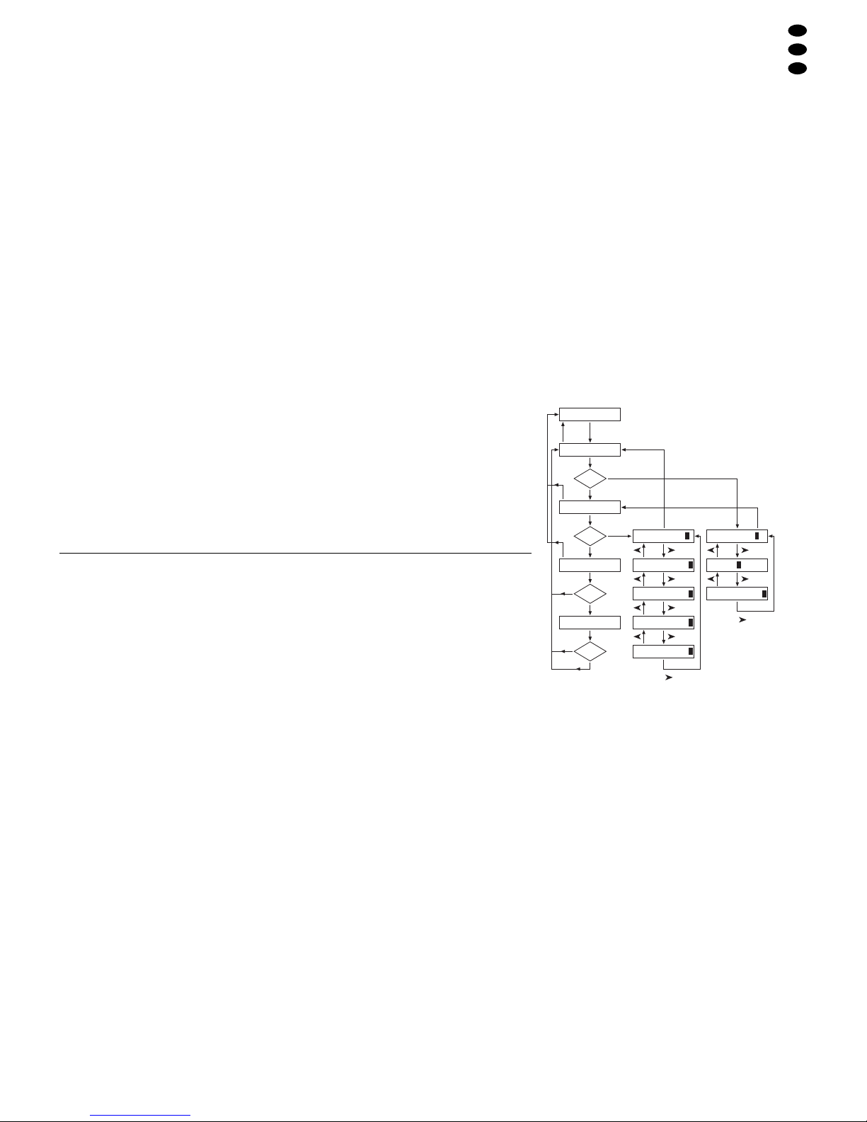
2) Das Konfigurationsmenü mit der Taste ESC/
SETUP (21) aufrufen. Dies kann jedoch nicht
beim Ablauf oder Programmierung einer Szenensequenz erfolgen. Die Menüstruktur ist in der
Abb. 4 dargestellt.
3) Das Display zeigt „Output Options? Y/N“.
a) Um die DMX-Adressen zuzuordnen (Kap.
4.4.1), die Zifferntaste 12/YES (2) drücken
(Anzeige „DMX Patch“) oder
b) um die Optionen der Steuerkanäle festzule-
gen (Kap. 4.4.2), die Taste 11/NO (2) drücken
(Anzeige „Control Options? Y/N“).
Entweder zum Bestätigen die Taste 12/ YES
drücken oder um zur Zurücksetzfunktion zu
gelangen (Kap. 4.4.3), die Taste 11/NO.
4) Mit der Taste ESC/SETUP kann jeweils das Konfigurationsmenü verlassen werden.
calculated by the controller can be switched off
separately for each control channel.
– The 240 memorized scenes can be combined in
60 sequences. There are 2 sequence types: sequences for which an individual crossfading time is
programmed for each of the maximum of 60 steps
and sequences with the maximum of 120 steps
with the same crossfading time for all steps. In this
case, the crossfading time is adjusted with the
control C.F. TIME during the reproduction.
– The sequences can run manually or automati-
cally, forward or backward. The automatic run
can be made time-controlled or music-controlled.
During the run, manual intervention is possible
(e.g. for change of direction).
4 Setting into Operation
4.1 Setting up the unit
The controller DMX-1440 is provided for mounting
into a rack (482 mm/ 19"). For this purpose 4 rack
spaces are required (1 rack space = 44.45mm). However, it is also possible to use it as a table-top unit.
4.2 Connecting the units
Prior to connecting units or changing existing connections switch off the controller and all connected
light effect units.
1) Connect the DMX output of the controller to the
DMX input of the first light effect unit. Depending
on the jack of the light effect unit, use the 3-pole
or the 5-pole XLR jack DMX OUT (31). (The XLR
jacks have a latching. To remove a plug, press
the PUSH lever.)
For the connection, special cables for high
data flow should be used. The use of standard
microphone cables can only be recommended for
a total cable length of up to 100 m. The best
transmission results are obtained with a screened
microphone cable of 2 x 0.25 mm
2
or a special
data transmission cable. For cable lengths ex-
ceeding 150m it is recommended to insert a
DMX level matching amplifier (e.g. SR-103DMX
or SR-105DMX from “img Stage Line”).
2) Connect the DMX output of the first light effect
unit to the DMX input of the next light effect unit.
Connect its output to the input of the subsequent
unit etc. until all light effect units are connected in
one row (also see fig. 3).
3) Terminate the DMX output of the last light effect
unit in the row with a 120Ω resistor (0.25W): Solder the resistor to the pins 2 and 3 of an XLR plug
and connect the plug to the DMX output.
4) For music-controlled run of a scene sequence
(chapter 7.2) it is possible to connect an audio
unit with line output (CD player, tape deck, mixer ,
etc.) to the jack AUDIO IN (32). When connecting
the audio unit to the jack, the internal microphone
(4) is switched off.
5) Finally connect the mains plug of the cable (30)
to a mains socket (230V~/50Hz).
4.3 Adjusting the DMX start addresses of the
light effect units
Prior to switching on the complete lighting system,
the connected light effect units have to be split to the
144 available DMX addresses. This cannot be made
according to a given scheme because the light effect
units, depending on the type, reserve a different
number of DMX channels (also see fig. 7 on page
19). Each light effect unit must be adjusted to a start
address, e.g. to the address by which the first function is controlled, e. g. address 19 for panning a
scanner. If the scanner reserves three further channels, e.g. for tilting, change of colour, and change of
gobo, the subsequent addresses 20, 21, and 22 are
automatically assigned. For synchronous control of
identical units only, they can receive the same start
address, otherwise each unit must receive a blank,
individual address.
The number of the required DMX channels, their
functions, and the adjustment of the DMX start
address can be taken from the respective operating
manual of the light effect unit.
4.4 Configuring control channels
To get an overview of the various possibilities of configuration, information is given on pages 18 and 19.
This should be noted prior to starting the configuration to use all possibilities in an optimum way.
1) Switch on the controller with the switch POWER
(8). The display shortly indicates “img Stage Line
DMX-1440” and the number of the software version. Then “Bk01 01/01” is displayed in the first
line. The scene 01 is called from the memory
bank 01 (see chapter 6).
2) Call the configuration menu with the button ESC/
SETUP (21). However, this cannot be made
when a scene sequence is run or programmed.
The menu structure is shown in fig. 4.
3) The display shows “Output Options? Y/N”.
a) To assign the DMX addresses (chapter 4.4.1),
press the numerical key 12/ YES (2) [display
“DMX Patch”] or
b) to define the options of the control channels
(chapter 4.4.2), press the button 11/NO (2)
[display “Control Options? Y/N”].
Either press the button 12/YES to confirm or
press the button 11/NO to go to the reset function (chapter 4.4.3).
4) With the button ESC/SETUP it is possible to exit
the configuration menu in each case.
7
Output Options?
ESC/
SETUP
NO
YES
Control Options?
NO
YES
Reset All Opt’s?
NO
YES
Bk 01/01
Sure ? ? ?
NO
YES
Control Ch: 01
Master Depend: Y
DMX Patch Ch:001
Crossfade: Y
Blackout: Y
Full/Flash: Y
ESC/
SETUP
or
ESC/
SETUP
ESC/
SETUP
Ctrl Ch:01 Inv:N
Ctrl Ch:01 Inv:N
ESC/
SETUP
or
ESC/
SETUP
ESC/
SETUP
ESC/
SETUP
Fig. 4 Menüstruktur/ Menu structure
D
A
CH
4.4.1 DMX-Adressen zuordnen (DMX-PATCH)
und Ausgabewerte invertieren
Nach der Bestätigung der Frage „Output Options?“
mit der Taste 12/ YES (2) zeigt das Display „DMX
Patch“ und es können die DMX-Adressen 1– 144 je
einem Steuerkanal 1 – 96 zugeordnet und die Ausgabewerte invertiert werden. Voreingestellt ist:
Abb. 5 Voreinstellung
1) Um die Voreinstellung zu ändern, mit den Ziffern-
tasten 12/ + und 11/
-
(2) oder per dreistelliger
Direkteingabe über die Zifferntasten 1– 0 die
DMX-Adresse „DMX Patch Ch: …“ auswählen.
2) Mit der Cursor-Taste (23) auf „Ctrl Ch: ..“
springen und mit den Tasten 12/+ und 11/
-
oder
per zweistelliger Direkteingabe über die Zifferntasten den Steuerkanal zuweisen. Verschiedene
DMX-Adressen können auch einem gemeinsamen Steuerkanal zugewiesen werden, um so
gleiche Funktionen mehrerer DMX-Geräte parallel steuern zu können.
Wird einer DMX-Adresse der Steuerkanal Null
zugeordnet (Ctrl Ch:00), bleibt der Ausgabewert
immer auf Minimum (bzw. bei Invertierung auf
Maximum). Damit lässt sich ein „kritischer“
Kanal, der z.B. eine Reset-Funktion für ein Gerät
auslöst oder eine Entladungslampe ausschaltet,
gegen unbeabsichtigte Bedienung schützen.
3) Mit der Taste zur Invertieroption „Inv:“ springen
und mit der Taste 12/ YES oder 11/ NO wählen,
ob der DMX-Ausgabewert invertiert werden soll
(Anzeige „Y“) oder nicht (Anzeige „N“). Bei aktivierter Invertierung ist der Ausgabewert Null,
wenn der Steuerkanal auf Maximalwert gestellt
wurde und umgekehrt.
4) Mit der Taste ESC/SETUP (21) oder der CursorTaste auf die Eingabe einer neuen DMXAdresse springen. Die Bedienschritte für weitere
Adressen wiederholen oder zum Verlassen der
Adressenzuordnung die Taste ESC/ SETUP erneut betätigen (Anzeige: „Control Options? Y/N“).
Nach der Frage „Control Options?“ kann mit
der Taste ESC/SETUP das Konfigurationsmenü
verlassen werden oder mit der Taste 12/YES zur
Einstellung der Steuerkanaloptionen gesprungen
werden (Anzeige: „Control Ch: 01“, Kap. 4.4.2).
Auf den Seiten 54 und 55 ist eine Tabelle zu Herauskopieren abgebildet, in der Sie die angeschlossenen
DMX-Geräte, deren eingestellte Adressen, Funktionen
und die Steuerkanalkonfiguration eintragen können.
4.4.2 Optionen der Steuerkanäle festlegen
Nach der Bestätigung der Frage „Control Options?“
mit der Taste12/ YES (2) können für jeden der 96
Steuerkanäle getrennt die folgenden Eigenschaften
festgelegt werden:
1. Ausgabewert ist vom Schieberegler MASTER
LEVEL (15) abhängig
2. Kanal ist bei Szenenwechsel überblendbar
3. Kanal reagiert auf die Taste BLACKOUT (29)
4. Kanal reagiert auf die Flash-Tasten (12) und die
Taste FULL ON (28)
In der Voreinstellung sind für alle Steuerkanäle
diese Optionen aktiviert.
1) Um die Voreinstellung für einen Steuerkanal zu
ändern, mit den Tasten 12/ + und 11/
-
(2) oder
per zweistelliger Direkteingabe über die Zifferntasten den Steuerkanal auswählen.
2) Mit der Cursor-Taste (23) auf den Parameter
„Master Depend:“ springen. Mit der Taste 12/
YES oder 11/NO wählen, ob der Wert des Kanals
vom Master-Regler abhängig sein soll (Anzeige
„Y“) oder nicht (Anzeige „N“).
Eine Abhängigkeit vom Master-Regler ist sehr
sinnvoll für Kanäle zur Steuerung der Helligkeit,
damit die Helligkeit einer Szene mit Hilfe des
Master-Reglers für alle Lampen gemeinsam gedimmt werden kann. Bei anderen Kanälen, wie
z.B. für Bewegungssteuerung (Pan/Tilt) oder
Farbwahl sollte diese Option ausgeschaltet sein.
3) Mit der Cursor-Taste auf den Parameter
„Crossfade:“ springen. Mit der Taste 12/YES
oder 11/NO wählen, ob der Kanal überblendbar
sein soll (d.h. das Steuerpult berechnet während
einer Überblendung für diesen Kanal Werte zwischen dem Wert der Startszene und der Zielszene
und gibt sie aus) oder nicht (zu Beginn einer Überblendung wird sofort der Zielwert ausgegeben).
Die Überblendbarkeit ist sinnvoll bei Kanälen
zur Steuerung der Helligkeit und der Bewegung
(Pan/Tilt). Bei Kanälen zur Farb- oder GoboWahl kann eine Überblendung mit Zwischenwerten störend wirken.
4) Mit der Cursor-Taste auf den Parameter
„Blackout:“ springen. Mit der Taste 12/YES
oder 11/NO wählen, ob der Steuerkanal auf die
Taste BLACKOUT (29) reagieren soll (d. h. im
Blackout-Zustand hat der Steuerkanal den Wert
Null) oder nicht.
Die Blackout-Funktion ist sinnvoll bei Kanälen
zur Steuerung der Helligkeit, der Blende, ggf.
auch der Gobos, wenn darüber ein schnelles Abdunkeln erreicht wird. Bei Kanälen zur Bewegungssteuerung sollte die Blackout-Funktion
immer ausgeschaltet werden.
5) Mit der Cursor-Taste auf den Parameter
„Full/Flash:“ springen. Mit der Taste 12/ YES
4.4.1 Assigning DMX addresses (DMX PATCH)
and inverting output values
After confirming the question “Output Options?” with
the button 12/YES (2) the display shows “DMX
Patch” and it is possible to assign the DMX addresses 1– 144 to one control channel 1–96 each and to
invert the output values. The following values are
preset:
Fig. 5 Presetting
1) To change the presetting, select the DMX ad-
dress “DMX Patch Ch: ...” with the numerical
keys 12+ and 11/
-
(2) or via the numerical keys
1–0 by 3-digit direct input.
2) Go to “Ctrl Ch: ..” with the cursor key (23) and
assign the control channel with the buttons 12/+
and 11/
-
or via the numerical keys by two-digit
direct input. Different DMX addresses can also
be assigned to a common control channel to be
able to control the same functions of several
DMX units in parallel.
If the control channel zero is assigned to a
DMX address (Ctrl Ch:00), the output value
always remains at minimum (or in case of inversion at maximum). Thus, a “critical” channel
which e.g. releases a reset function for a unit or
switches off a discharge lamp can be protected
against unintentional operation.
3) Go to the inversion option “Inv:” with the button
and select with the button 12/YES or 11/NO if the
DMX output value is to be inverted (indication
“Y”) or not (indication “N”). With activated inversion the output value is zero if the control channel
has been set to the maximum value and vice
versa.
4) Go to the input of a new DMX address with the
button ESC/ SETUP (21) or the cursor key .
Repeat the operating steps for further addresses
or actuate the button ESC/ SETUP again to exit
the address assignment (indication: “Control
Options? Y/N”).
After the question “Control Options?” it is possible to exit the configuration menu with the button ESC/SETUP or to go to the adjustment of the
control channel options with the button 12/ YES
(indication: “Control Ch: 01”, chapter 4.4.2).
Atable for copying is shown on pages 54 and 55 into
which you can enter the connected DMX units, their
adjusted addresses, functions, and the configuration
of the control channel.
4.4.2 Defining the options of the control channels
After confirming the question “Control Options?”
with the button 12/ YES (2), it is possible to define
the subsequent characteristics separately for each
of the 96 control channels:
1. Output value depends on the sliding control
MASTER LEVEL (15)
2. Channel can be crossfaded when changing a
scene
3. Channel reacts on the button BLACKOUT (29)
4. Channel reacts on the flash buttons (12) and the
button FULL ON (28)
These options are activated for all control channels
in the presetting.
1) To change the presetting for a control channel,
select the control channel with the buttons 12/+
and 11/
-
(2) or via the numerical keys by two-
digit direct input.
2) Go to the parameter “Master Depend:” with the
cursor key (23). With the button 12/ YES or
11/ NO define whether the value of the channel is
to depend on the master fader (indication “Y”) or
not (indication “N”).
For channels controlling the brightness, it is
very useful to depend on the master fader so that
the brightness of a scene can be dimmed with the
master fader for all lamps in common. This option
should be switched off for other channels, e. g.
for motion control (pan/tilt) or colour selection.
3) Go to the parameter “Crossfade:” with the cursor key . Define with the button 12/ YES or
11/ NO whether a crossfading of the channel
should be possible (i.e. during a crossfading, the
controller calculates for this channel values between the start scene value and the target scene
value and sends them to the output) or not (at the
beginning of a crossfading the target value is
immediately sent to the output).
The possibility of crossfading is useful for
channels controlling the brightness and the
motion (pan/tilt). For channels selecting the
colour or gobo, crossfading with interim values
may have a disturbing effect.
4) Go to the parameter “Blackout:” with the cursor
key . Select with the button 12/ YES or 11/ NO
whether the control channel is to react on the button BLACKOUT (29) [i. e. in the blackout state
the control channel has the value zero] or not.
The blackout function is useful for channels
controlling the brightness, the iris, and, if necessary, also the gobos if a quick darkening is
reached by this function. The blackout function
should always be switched off for channels which
control the motion.
8
D
A
CH
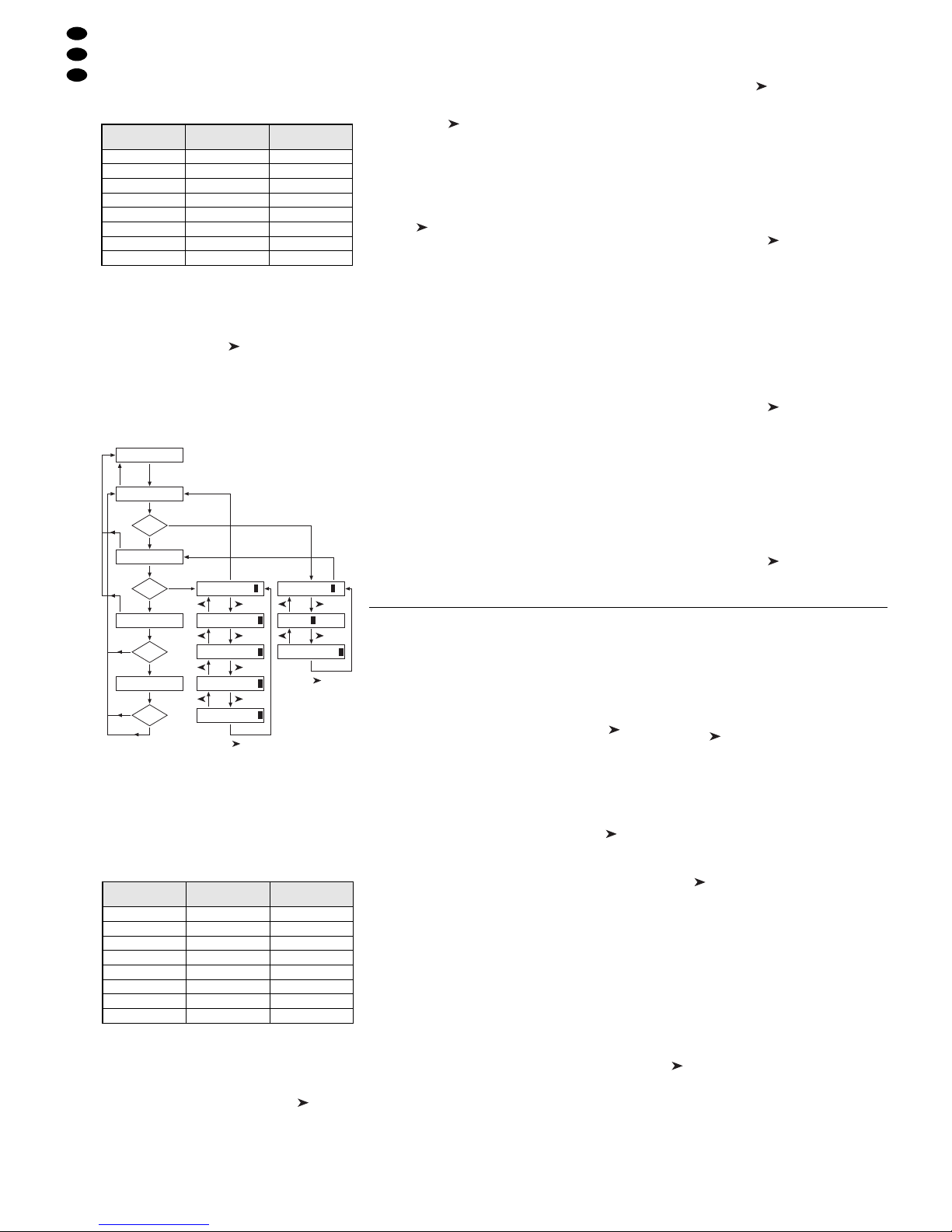
DMX-Adresse
„DMX Patch Ch:“
Steuerkanal
„Ctrl Ch:“
Invertierung
„Inv:“
001 01 N (nein)
002 02 N
………
096 96 N
097 01 N
098 02 N
………
144 48 N
DMX address
“DMX Patch Ch:”
Control channel
“Ctrl Ch:”
Inversion
“Inv:”
001 01 N (no)
002 02 N
………
096 96 N
097 01 N
098 02 N
………
144 48 N
Output Options?
ESC/
SETUP
NO
YES
Control Options?
NO
YES
Reset All Opt’s?
NO
YES
Bk 01/01
Sure ? ? ?
NO
YES
Control Ch: 01
Master Depend: Y
DMX Patch Ch:001
Crossfade: Y
Blackout: Y
Full/Flash: Y
ESC/
SETUP
or
ESC/
SETUP
ESC/
SETUP
Ctrl Ch:01 Inv:N
Ctrl Ch:01 Inv:N
ESC/
SETUP
or
ESC/
SETUP
ESC/
SETUP
ESC/
SETUP
Fig. 6 Menüstruktur/ Menu structure

oder 11/NO wählen, ob der Steuerkanal auf die
Flash-Tasten (12) und die Taste FULL ON (28)
reagieren soll (d.h. beim Drücken dieser Tasten
wird der Steuerkanal auf den Maximalwert gestellt) oder nicht.
Die Flash-Funktion ist sinnvoll bei Kanälen zur
Steuerung der Helligkeit, der Blende, ggf. auch
der Gobos. Bei Kanälen zur Bewegungssteuerung und zur Reset-Auslösung sollte die FlashFunktion immer ausgeschaltet werden.
6) Mit der Taste ESC/ SETUP (21) oder auf die
Eingabe einer neuen Steuerkanalnummer springen. Die Bedienschritte für weitere Kanäle wiederholen oder zum Verlassen der Optionseinstellungen die Taste ESC/ SETUP erneut betätigen
(Anzeige: „Output Options? Y/N“). Um das
Menü zu verlassen, die Taste ESC/SETUP noch
einmal drücken.
4.4.3 Zurücksetzen sämtlicher Adressenzuord-
nungen und Steuerkanaloptionen
Alle vorgenommenen Adressenzuordnungen und
Steuerkanaloptionen lassen sich bei Bedarf auf die
Voreinstellungen (siehe Abb. 5 und Kap. 4.4.2 nach
1. Absatz) zurücksetzen.
1) Das Konfigurationsmenü mit der Taste ESC/
SETUP (21) aufrufen.
Anzeige: „Output Options? Y/N“.
2) Die Taste 11/NO (2) drücken.
Anzeige: „Control Options? Y/N“.
3) Die Taste 11/NO erneut drücken.
Anzeige „Reset All Opt’s? Y/N“.
4) Entweder zum Bestätigen die Taste 12/ YES drücken, Anzeige: „Reset All Opt’s? Sure ? ? ?
Y/N“ oder die Taste 11/NO drücken, wenn keine
Rücksetzung erfolgen soll.
5) Wird die Frage „Reset All Opt’s? Sure ? ? ?“ mit
der T aste 12/ YES bejaht, erfolgt die Rücksetzung.
Das Display zeigt wieder „Output Options? Y/N“.
Jetzt können die Steuerkanäle neu konfiguriert
werden (Taste 12 / YES drücken) oder das Menü
kann mit der T aste ESC/SETUPverlassen werden.
5 Bedienung im Direkt-Modus
Das Steuerpult mit dem Schalter POWER (8) einschalten. Das Display zeigt kurz „img Stage Line
DMX-1440“ und die Nummer der Software-Version.
Danach erscheint in der ersten Zeile „Bk01 01/01“.
Nach dem Einschalten ist immer die 1. Szene aus
der Speicherbank 1 aufgerufen. Deshalb sollte für
diese Szene eine geeignete Basisbeleuchtung gespeichert werden (Kap. 6.1).
5.1 Beleuchtungsszene einstellen
1) Mit den Tasten CONTROL CHANNEL PAGE (1)
die Gruppe wählen, in der die einzustellenden
Steuerkanäle liegen (1– 12, 13–24, 25–36,
37– 48, 49–60, 61 –72, 73– 84, 85–96).
Sollen in verschiedenen Gruppen liegende
Kanäle gleichzeitig auf denselben Wert eingestellt
werden, können auch mehrere Gruppen gewählt
werden. Dazu die entsprechenden Tasten gleichzeitig drücken. Die LEDs neben den Tasten zeigen die aktivierten Gruppen an.
2) Zur Grundeinstellung den Regler MASTER
LEVEL (15) ganz nach oben auf Maximum schieben. Dann mit den grauen Schiebereglern (14)
die gewünschten Einstellungen vornehmen. Wird
ein Regler bewegt, so zeigt das Display (6) in der
unteren Zeile die Nummer des Steuerkanals,
z. B. „C15:“ und den momentanen Ausgabewert
als DMX-Wert und in Prozent (bezogen auf den
Maximalwert), z.B. „118= 46%“. Ist bei der Steuerkanalkonfiguration festgelegt worden, dass
dieser Kanal vom Regler MASTER LEVEL (15)
abhängig sein soll und steht der Regler MASTER
LEVEL nicht auf Maximum, wird zusätzlich noch
der resultierende Ausgabewert in Prozent angezeigt (z.B. „
" 23 %“).
Wird einer der grauen Schieberegler erstmalig
nach dem Anwählen einer Steuerkanalgruppe
bewegt, reagiert der Ausgabewert nicht sofort auf
die Bewegung des Reglers. Der vom Display
angezeigte Ausgabewert muss erst mit dem Regler „abgeholt“ werden. Die Einstellung auf einen
neuen Wert wird dann wirksam, wenn der Regler
zuvor auf die Position geschoben wurde, die dem
angezeigten Ausgabewert entspricht. Sind mehrere Kanalgruppen gleichzeitig angewählt, muss
immer der Ausgabewert des Kanals mit der niedrigsten Nummer „abgeholt“ werden. Auf diese
Weise treten keine abrupten Sprünge der Ausgabewerte auf, wenn auf eine andere Steuerkanalgruppe oder Beleuchtungsszene umgeschaltet
wird.
3) Als Ausgangsposition können alle Steuerkanäle
auf den Wert Null gesetzt werden. Dazu folgende
Tasten nacheinander betätigen:
STORE/PRG (22)
DELETE (24)
STORE/PRG
Tipp Nach dem Einschalten des Gerätes alle
grauen Schieberegler nach unten auf Null
schieben. Dann den Steuerkanälen den
Wert Null zuweisen. Dadurch reagieren die
Ausgabewerte sofort beim Betätigen der
Schieberegler.
5.2 Bedienung des Steuerhebels
Vier Steuerkanäle jeder Kanalgruppe können alternativ zu den Schiebereglern über den Steuerhebel
(18) eingestellt werden. Die beiden Kanalpaare 1+ 2
sowie 7 + 8 jeder Gruppe lassen sich unabhängig
voneinander aktivieren (Bewegung horizontal = 1.
oder 7. Kanal, vertikal = 2. oder 8. Kanal).
Zum Aktivieren die Taste STICK CONTROL
ASSIGN 1/2 (17) und /oder 7/ 8 (19) drücken. Die
zugehörige LED STICK CTRL (11, 13) zeigt, dass
der Steuerhebel für die entsprechenden Kanäle der
gewählten Gruppe (n) aktiv ist. Zur Deaktivierung
die Taste nochmals drücken.
Hinweise
a) Bei aktiviertem Steuerhebel werden die Werte für
die entsprechenden Kanalpaare, im Gegensatz
zu der Einstellung über die Schieberegler, ungeachtet der letzten Ausgabewerte unmittelbar
übernommen.
5) Go the parameter “Full/Flash:” with the cursor
key . Define with the button 12/YES or 11/NO
whether the control channel is to react on the
flash buttons (12) and the button FULL ON (28)
[i. e. when pressing these buttons, the control
channel is set to the maximum value] or not.
The flash function is useful for channels controlling the brightness, the iris, and, if necessary,
also the gobos. The flash function should always
be switched off for channels which control the
motion and release the reset.
6) With the button ESC/SETUP (21) or go to the
input of a new control channel number. Repeat
the operating steps for further channels or
actuate the button ESC/SETUP again to exit the
adjustments of the options (indication: “Output
Options? Y/N”). To exit the menu, press the key
ESC/SETUP once again.
4.4.3 Reset of all address assignments and con-
trol channel options
All address assignments and control channel options
made can be reset to the presettings, if necessary
(see fig. 5 and chap. 4.4.2 after the first paragraph).
1) Call the configuration menu with the button ESC/
SETUP (21).
Indication: “Output Options? Y/N”.
2) Press the button 11/NO (2).
Indication: “Control Options? Y/N”.
3) Press the button 11/NO again.
Indication “Reset All Opt’s? Y/N”.
4) Either press the button 12/YES, indication:
“Reset All Opt’s? Sure ? ? ? Y/N” to confirm or
the button 11/NO if no reset is to be made.
5) If the question “Reset All Opt’s? Sure ? ? ?” is
affirmed with the button 12/YES, the unit will be
reset. The display indicates again “Output Options? Y/ N”. Now the control channels can be
reconfigured (press the button 12/ YES) or the
menu can be exited with the button ESC/SETUP.
5 Operation in the Direct Mode
Switch on the controller with the POWER switch (8).
The display shortly indicates “img Stage Line DMX1440” and the number of the software version. Then
“Bk01 01/01” is displayed in the first line. After
switching-on, always the first scene from the memory
bank 1 is called. Therefore, a suitable basic illumination should be memorized for this scene (chap. 6.1).
5.1 Adjusting an illumination scene
1) With the buttons CONTROL CHANNELPAGE (1)
select the group in which the control channels to
be adjusted are located (1–12, 13 – 24, 25 – 36,
37– 48, 49–60, 61 –72, 73– 84, 85–96).
For adjusting channels located in different
groups to the same value at the same time, it is
also possible to select several groups. For this
purpose press the corresponding buttons at the
same time. The LEDs next to the buttons show
the activated groups.
2) For the basic adjustment slide the fader MASTER LEVEL (15) fully upwards to the maximum
position. Then make the desired adjustments
with the grey sliding controls (14). If a control is
moved, the display (6) shows the number of the
control channel in the lower line, e.g. “C15:” and
the current output value as a DMX value and in
per cent (referred to the maximum value), e. g.
“118 = 46 %”. If it has been defined for the configuration of the control channel that this channel
is to depend on the fader MASTER LEVEL (15)
and if the fader MASTER LEVEL is not in the
maximum position, the resulting output value is
additionally indicated in per cent (e.g. “
" 23%”).
If one of the grey sliding controls is moved for
the first time after selecting a control channel
group, the output value does not react immediately on the movement of the sliding control. The
output value indicated by the display must first be
“fetched” with the fader. The adjustment to a new
value is effective if the fader has previously been
slid to the position which corresponds to the out-
put value indicated. If several channel groups are
selected at the same time, always the output
value of the channel with the lowest number must
be “fetched”. This way no abrupt jumps of the output values occur when the unit switches to another control channel group or illumination scene.
3) All control channels can be set to the value zero
as an initial position. For this purpose actuate the
following buttons one after the other:
STORE/PRG (22)
DELETE (24)
STORE/PRG
Note After switching on the unit, slide all grey
sliding controls downwards to zero. Then
assign the value zero to the control channels. Thus, the output values immediately
react when actuating the sliding controls.
5.2 Operating the control lever
Four control channels of each channel group may
be adjusted alternatively to the sliding controls via
the control lever (18). The two channel pairs 1 + 2
and 7+ 8 of each group can be activated independently of each other (movement horizontal = 1st or
7th channel, vertical = 2nd or 8th channel).
To activate, press the button STICK CONTROL
ASSIGN 1/2 (17) and / or 7/8 (19). The respective
LED STICK CTRL (11, 13) shows that the control
lever for the corresponding channels of the selected
group(s) is active. To deactivate, press the button
once again.
Notes
a) With activated control lever, contrary to the
adjustment via the sliding controls, the values for
the corresponding channel pairs are immediately
taken over, irrespective of the last output values.
b) A fine adjustment of the channels can be made
after the deactivation of the control lever via the
sliding controls.
c) When calling a scene (chapter 6.2), the control
lever is automatically deactivated.
9
GB
D
A
CH

b) Eine Feineinstellung der Kanäle kann nach der
Deaktivierung des Steuerhebels über die Schieberegler erfolgen.
c) Beim Aufrufen einer Szene (Kap. 6.2) wird der
Steuerhebel automatisch deaktiviert.
d) Der Steuerhebel ist speziell für Kanäle zur Bewe-
gungssteuerung (z.B. Pan/Tilt bei Scannern
oder Moving Heads) vorgesehen. Dieses sollte
bei der Konfiguration der Steuerkanäle berücksichtigt werden (Kap. 4.4.1).
e) Bei Kanälen, die über den Steuerhebel bedient
werden, sollte die Beeinflussung durch den Regler MASTER LEVEL (15) beim Konfigurieren der
Steuerkanäle ausgeschaltet werden (Kap. 4.4.2).
Anderenfalls kann es sonst bei aktivem Steuerhebel und gleichzeitiger Betätigung des Reglers
MASTER LEVEL zu Wertsprüngen kommen.
5.3 Beleuchtungsszene mit dem Regler
MASTER LEVEL dimmen
Mit dem Regler MASTER LEVEL (15) lassen sich
alle helligkeitssteuerbaren DMX-Geräte gleichzeitig
dimmen. Beim Betätigen des Reglers zeigt das Display in der unteren Zeile den eingestellten Wert in
Prozent vom Maximalwert an (z.B. „Master: 25 %“).
Wurde zum Beispiel ein Steuerkanal für die Helligkeit auf 50% eingestellt, beträgt bei einem Masterwert von 50% der Ausgabewert 25%.
Damit durch den MASTER-Regler auch nur die
Helligkeit der Szene verändert wird, unbedingt beim
Konfigurieren der Steuerkanäle die Funktion „Master Depend“ für die Kanäle ausschalten, die nicht zur
Helligkeitseinstellung dienen (Kap. 4.4.2). Anderenfalls wechseln die DMX-Geräte beim Betätigen des
MASTER-Reglers z. B. auch die Farbe, das Gobo
oder den Lichtabstrahlwinkel.
5.4 Steuerkanäle auf den Maximalwert
schalten (max. Helligkeit)
Falls die rote LED FL. CH. (Flash Channel) neben
der Taste FLASH MODE (10) nicht leuchtet, die
Taste FLASH MODE entsprechend oft betätigen. Es
lässt sich dann durch Gedrückthalten einer FlashTaste (12) der Wert des zugehörigen Steuerkanals
(oder der zugehörigen Steuerkanäle, wenn mehrere
Kanalgruppen angewählt sind) auf Maximum schalten, um z. B. das entsprechende DMX-Gerät auf
maximale Helligkeit zu stellen. Die Position des
Reglers MASTER LEVEL (15) hat hierbei keinen
Einfluss. Beim Konfigurieren der Steuerkanäle (Kap.
4.4.2) lässt sich die Funktion „Full/ Flash“ für jeden
Kanal separat ausschalten, um z.B. bei Kanälen zur
Bewegungssteuerung eine Fehlbedienung auszuschließen.
Um mehrere Steuerkanäle mit einer Flash-Taste
gleichzeitig auf den Maximalwert zu schalten, lassen sich diese zu einer Flash-Gruppe zusammenfassen (Kap. 5.4.1).
5.4.1 Flash-Gruppen nutzen
Die linken fünf Flash-Tasten (12) lassen sich auch
zum Aufrufen von fünf Flash-Gruppen nutzen. Alle
Steuerkanäle, die einer Flash-Gruppe zugeordnet
sind, werden dann mit der entsprechenden FlashTaste auf den Maximalwert geschaltet.
1) Zuerst die gewünschten Kanäle der ersten Flash-
Gruppe zusammenfassen:
a) Die Taste FLASH MODE (10) gedrückt halten
und dabei die Taste STORE/PRG (22) betätigen. Daraufhin leuchten die rote und die gelbe
LED neben der Taste FLASH MODE.
b) Die Kanäle für die Gruppe mit den Flash-Tas-
ten auswählen. Dabei kann jeder Steuerkanal,
abhängig von der eingeschalteten Steuerkanalgruppe, angewählt (d. h. auf Maximalwert)
oder bei versehentlicher Anwahl durch erneutes Drücken wieder abgewählt werden
(d.h. auf aktuellen Kanalwert zurück). Zur besseren Unterscheidung, ob ein Kanal auf Maximum geschaltet ist oder nicht, sollten die ent-
sprechenden Steuerkanäle vor der Zuordnung
auf einen niedrigen Wert gestellt werden.
c) Sind alle gewünschten Kanäle ausgewählt,
die Taste STORE/PRG drücken. Die rote LED
FL.CH. erlischt.
d) Jetzt mit den Flash-Tasten die Gruppennum-
mer (1 – 5) wählen, unter der die Einstellung
gespeichert werden soll.
Ohne die Zuordnung zu speichern, kann
der Vorgang an jeder Stelle mit der Taste
FLASH MODE abgebrochen werden.
2) Zur Speicherung weiterer Flash-Gruppen die Bedienschritte 1a bis 1d wiederholen. Dabei kann
aber auch von einer bereits gespeicherten
Gruppe (oder von der Kombination mehrerer
Gruppen) ausgegangen werden. Dazu den Programmiervorgang wie folgt beginnen:
a) Die Taste FLASH MODE so oft betätigen, bis
neben ihr die gelbe LED FL.GRP. leuchtet.
b) Die Taste(n) der Flash-Gruppe(n), von der
(denen) ausgegangen werden soll, gedrückt
halten und dabei die Taste STORE/PRG (22)
betätigen. Daraufhin leuchten die rote und die
gelbe LED neben der Taste FLASH MODE
und die Kanäle der entsprechenden Gruppen
sind bereits auf den Maximalwert geschaltet.
c) Mit der Programmierung, wie unter 1b bis 1d
beschrieben, fortfahren.
3) Die gespeicherten Flash-Gruppen können nun
aufgerufen werden:
a) Falls die gelbe LED FL. GRP. (Flash Group)
neben der Taste FLASH MODE nicht leuchtet,
die Taste FLASH MODE entsprechend oft betätigen.
b) Durch Gedrückthalten der Flash-Taste, unter
der die gewünschte Flash-Gruppe gespeichert wurde, diese Gruppe auf den Maximalwert schalten.
c) Um wieder einzelne Steuerkanäle auf den
Maximalwert schalten zu können, die Taste
FLASH MODE so oft betätigen, bis die rote
LED FL.CH. (Flash Channel) leuchtet.
d) The control lever is especially provided for chan-
nels for motion control (e.g. pan/tilt for scanners or
moving heads). This should be considered when
the control channels are configured (chap. 4.4.1).
e) For channels which are operated via the control
lever, the influence by the fader MASTER LEVEL
(15) should be switched off when configuring the
control channels (chapter 4.4.2). Otherwise value
jumps may occur with active control lever and
simultaneous actuation of the fader MASTER
LEVEL.
5.3 Dimming an illumination scene with the
fader MASTER LEVEL
With the fader MASTER LEVEL (15) it is possible to
dim all DMX units simultaneously which can be controlled in brightness. When actuating the fader, the
display shows the adjusted value in per cent from
the maximum value in the lower line (e.g. “Master:
25 %”). If e. g. a control channel for the brightness
has been adjusted to 50 %, with a master value of
50% the output value is 25 %.
To change only the brightness of the scene by the
MASTER fader, when configuring the control channels, in any case switch off the function “Master
Depend” for the channels which do not serve for
brightness adjustment (chapter 4.4.2). Otherwise
the DMX units change e.g. also the colour, the
gobo, or the light radiation angle when actuating the
MASTER fader.
5.4 Setting the control channels to the maximum value (maximum brightness)
If the red LED FL. CH. (flash channel) next to the
button FLASH MODE (10) does not light up, actuate
the button FLASH MODE as many as times as
necessary. The value of the corresponding control
channel (or of the corresponding control channels if
several channel groups are selected) can be set to
maximum by keeping a flash button (12) pressed,
e.g. to set the corresponding DMX unit to the maximum brightness. The position of the fader MASTER
LEVEL (15) has no effect during this process. When
configuring the control channels (chapter 4.4.2) the
function “Full/Flash” can be switched off separately
for each channel, e.g. to exclude a misoperation of
the channels for motion control.
To set several control channels with a flash button simultaneously to the maximum value, they can
be combined to a flash group (chapter 5.4.1).
5.4.1 Using the flash groups
The five left flash buttons (12) may also be used for
calling five flash groups. Then all control channels
which are assigned to one flash group will be set to
the maximum value with the corresponding flash
button.
1) First combine the desired channels of the first
flash group:
a) Keep the button FLASH MODE (10) pressed
and actuate the button STORE/ PRG (22) at
the same time. As a result the red and the yellow LEDs next to the button FLASH MODE
light up.
b) Select the channels for the group with the flash
buttons. Then each control channel, depending on the control channel group switched on,
can be selected (i.e. at maximum value) or in
case of accidental selection be cancelled by
actuating again (i.e. back to the current channel value). For better distinction if a channel is
set to maximum or not, the corresponding control channels should be set to a lower value
prior to the assignment.
c) If all desired channels are selected, press the
button STORE/PRG. The red LED FL.CH. is
extinguished.
d) Now select the group number (1 – 5) with the
flash buttons under which the adjustment is to
be memorized.
Without memorizing the assignment, the
procedure can be interrupted at any place with
the button FLASH MODE.
2) To memorize further flash groups, repeat the
operating steps 1a to 1d. It is also possible to proceed from a group already memorized (or from
the combination of several groups). For this purpose start the programming procedure as follows:
a) Actuate the button FLASH MODE so many
times until the yellow LED FL.GRP. next to it
lights up.
b) Keep the button(s) of the flash group(s)
pressed from which the unit is to proceed and
actuate the button STORE/ PRG (22) at the
same time. Then the red and the yellow LEDs
next to the button FLASH MODE light up and
the channels of the corresponding groups are
already set to the maximum value.
c) Continue the programming as described un-
der 1b to 1d.
3) The memorized flash groups may now be called:
a) If the yellow LED FL. GRP. (flash group) next
to the button FLASH MODE does not light up,
actuate the button FLASH MODE as many
times as necessary.
b) By keeping the flash button pressed under
which the desired flash group has been
memorized, set this group to the maximum
value.
c) To be able to switch individual control chan-
nels to the maximum value again, actuate the
button FLASH MODE so many times until the
red LED FL.CH. (flash channel) lights up.
10
GB
D
A
CH

5.4.2 Alle Steuerkanäle auf den Maximalwert
schalten
Durch Gedrückthalten der Taste FULL ON (28) lassen sich alle Steuerkanäle auf den Maximalwert
schalten, für die die Funktion „Full/Flash“ beim Konfigurieren der Kanäle nicht ausgeschaltet wurde
(Kap. 4.4.2).
5.5 Blackout-Funktion
Mit der Blackout-Funktion lässt sich z. B. eine Beleuchtungsszene komplett dunkel schalten. Mit der
Taste BLACKOUT (29) wird diese Funktion eingeschaltet: Die LED neben der Taste leuchtet und alle
Steuerkanäle, für die die Blackout-Funktion beim
Konfigurieren der Kanäle nicht ausgeschaltet wurde
(Kap. 4.4.2), werden auf den Ausgabewert Null geschaltet. Laufende Überblendungen und Sequenzen
werden durch die Blackout-Funktion nicht angehalten, sie laufen währenddessen „im Dunkeln“ weiter.
Ein erneutes Drücken der Taste BLACKOUT beendet die Funktion: Die LED erlischt und alle Kanäle
nehmen wieder ihre vorherigen Ausgabewerte ein.
5.6 Aktuelle Werte der Steuerkanäle anzeigen
Die aktuellen Werte der Steuerkanäle lassen sich im
Display anzeigen, ohne dass dazu der entsprechende Schieberegler betätigt werden muss.
1) Die Taste FLASH MODE (10) so oft betätigen, bis
neben ihr die grüne LED SH.VAL. (Show Value)
leuchtet.
2) Mit den Flash-Tasten (12) kann jetzt der Ausgabe-
wert des entsprechende Steuerkanals abgefragt
werden. Sind mehrere Steuerkanalgruppen gleich-
zeitig angewählt, so bezieht sich die Anzeige nur
auf den Kanal mit der niedrigsten Nummer.
Hinweise
a) Ist die Hold-Funktion (Kap. 5.7) aktiv, wird mit
dem Zusatz „held“ gezeigt, dass der Ausgabe-
wert momentan unabhängig von den Schiebe-
reglern konstant gehalten wird.
b) Während einer laufenden Überblendung, der Pro-
grammierung oder Wiedergabe einer Szenensequenz und während der Konfigurierung von
Steuerkanälen steht die Anzeigefunktion nicht zur
Verfügung.
5.7 Ausgabewerte festhalten (Hold-Modus)
und zur nächsten Szene überblenden
Der Hold-Modus lässt sich zum Überblenden auf die
nächste Beleuchtungsszene nutzen.
1) Die Taste HOLD (3) drücken. Die LED HOLD/
CROSSFADE unter der Taste leuchtet und die
Ausgabewerte werden festgehalten, d.h. sie
ändern sich nicht mehr beim Verstellen der
Schieberegler (14).
2) Für die nächste Szene neue Kanalwerte einstel-
len. Beim Betätigen eines Schiebereglers im
Hold-Modus zeigt das Display nicht den festgehaltenen Ausgabewert an, sondern den neu eingestellten Wert.
3) Wenn auf die neuen Kanalwerte übergeblendet
werden soll, den Hold-Modus durch erneutes
Drücken der Taste HOLD verlassen. Abhängig
von der eingestellten Überblendzeit (Kap. 5.7.1)
und der Überblendfähigkeit der einzelnen Steuerkanäle (Kap. 4.4.2), wird von den alten Kanalwerten zu den neuen übergeblendet. Während
des Überblendens blinkt die LED HOLD/
CROSSFADE. Danach erlischt sie.
5.7.1 Überblendzeit einstellen
Mit dem Regler C.F .TIME (7) wird die Überblendzeit
zwischen zwei Szenen eingestellt. Beim Betätigen
des Reglers erscheint in der unteren Zeile des Displays der gewählte Wert, z. B. „CFTime: 4.3s“ für
eine 4,3 Sekunden dauernde Überblendung von der
Startszene zur Zielszene.
Eine Überblendung kann aber auch manuell mit
dem Crossfader (16) erfolgen – siehe Kap. 5.7.2.
5.7.2 Überblenden mit dem Crossfader
1) Zum manuellen Überblenden mit dem Crossfader (16) den Regler C.F.TIME (7) in die Position MAN (Rechtsanschlag) drehen. Im Display
erscheint „CFTime: manu.“ Zusätzlich leuchtet
die grüne LED unterhalb des Crossfaders.
2) Vor einer Überblendung den Crossfader in eine
der Endpositionen ganz nach oben oder unten
schieben.
3) Die Taste HOLD (3) drücken und die Einstellung
für die neue Szene vornehmen (Kap. 5.7).
4) Zum Überblenden den Crossfader zur anderen
Endposition schieben. Während der Überblendung blinkt die LED unter der Taste HOLD. Beim
Erreichen der anderen Endposition ist die Überblendung beendet und die LED erlischt.
6 Szenenspeicher verwenden
Zum schnellen Abrufen von Kanalwerteinstellungen
können 240 Beleuchtungsszenen gespeichert werden. Dazu stehen 20 Speicherbanken für je 12 Szenen zur Verfügung. Jede Szene enthält die Werte
aller Steuerkanäle zum Zeitpunkt der Speicherung.
6.1 Speichern von Szenen
1) Alle Kanalwerte für die gewünschte Szene einstellen oder, wenn als Basis eine bereits gespeicherte Szene verwendet werden soll, diese aufrufen (Kap. 6.2).
Die Einstellung des Reglers MASTER LEVEL
(15) wird nicht mitgespeichert, damit sich eine
gespeicherte Szene immer im vollen Umfang
dimmen lässt. Damit kein falscher Eindruck von
der zu speichernden Szene entsteht, diesen
Regler ganz nach oben auf Maximum schieben.
2) Die Speicherbank wählen (die aktuelle Bank wird
oben links im Display angezeigt, z.B. „Bk01“):
a) entweder schrittweise mit den Cursor-Tasten
und (23) oder
5.4.2 Setting all control channels to the maximum value
By keeping the button FULL ON (28) pressed it is
possible to set all control channels to the maximum
value for which the function “Full/ Flash” has not
been switched off when configuring the channels
(chapter 4.4.2).
5.5 Blackout function
With the blackout function it is possible e.g. to blackout an illumination scene completely. With the button BLACKOUT (29) this function is switched on:
The LED next to the button lights up and all control
channels for which the blackout function has not
been switched off when configuring the channels
(chapter 4.4.2) are set to the output value zero. Current crossfadings and sequences are not stopped by
the blackout function, they continue “in the dark” in
the meantime.
By pressing the button BLACKOUT again, the
function stops: The LED is extinguished and all
channels return to their previous output values.
5.6 Displaying current values of the control
channels
It is possible to display the current values of the control channels without having to actuate the corresponding sliding control.
1) Actuate the button FLASH MODE (10) so many
times until the green LED SH.VAL. (show value)
next to it lights up.
2) With the flash buttons (12) it is now possible to
request the output value of the corresponding
control channel. If several control channel groups
are selected at the same time, the display only
refers to the channel with the lowest number.
Notes
a) If the hold function (chapter 5.7) is active, the
addition “held” shows that the output value is at
present kept constant, regardless of the sliding
controls.
b) While a current crossfading, programming, or
reproduction of a scene sequence is made and
while configuring control channels, the display
function is not available.
5.7 Holding the output values (hold mode)
and crossfading to the next scene
The hold mode can be used for crossfading to the
next illumination scene.
1) Press the button HOLD (3). The LED HOLD/
CROSSFADE below the button lights up and
the output values are kept, i.e. they do not
change any more when readjusting the sliding
controls (14).
2) For the next scene adjust new channel values.
When actuating a sliding control in the hold
mode, the display does not show the output value
held but the readjusted value.
3) For crossfading to the new channel values, exit
the hold mode by pressing the button HOLD
again. Depending on the adjusted crossfading
time (chapter 5.7.1) and the capability of crossfading the individual control channels (chapter 4.4.2), the unit crossfades from the old channel values to the new ones. While crossfading,
the LED HOLD/CROSSFADE flashes. Then it is
extinguished.
5.7.1 Adjusting the crossfading time
With the control C.F. TIME (7) the crossfading time
between two scenes is adjusted. When actuating
the control, the selected value, e.g. “CFTime: 4.3s”
for a crossfading lasting 4.3 seconds from the start
scene to the target scene is indicated in the lower
line of the display.
Crossfading can also manually be made with the
crossfader (16) – see chapter 5.7.2.
5.7.2 Crossfading with the crossfader
1) For manual crossfading with the crossfader (16)
turn the control C.F . TIME (7) to the position MAN
(right stop). In the display “CF Time: manu.” is
indicated. In addition, the green LED below the
crossfader lights up.
2) Prior to crossfading, slide the crossfader to one
of the end positions fully upwards or downwards.
3) Press the button HOLD (3) and make the adjustment for the new scene (chapter 5.7).
4) For crossfading, slide the crossfader to the other
end position. While crossfading, the LED below
the button HOLD flashes. When reaching the
other end position, the crossfading is stopped
and the LED is extinguished.
6 Using the Scene Memory
To call channel value adjustments quickly, 240 illumination scenes can be memorized. For this purpose 20 memory banks for 12 scenes each are
available. Each scene contains the values of all control channels at the time of the storage.
6.1 Memorizing scenes
1) Adjust all channel values for the desired scene
or, if a scene already memorized is to be used as
a basis, call this scene (chapter 6.2).
The adjustment of the fader MASTER LEVEL
(15) is not memorized so that it is always possible
to dim a memorized scene to the full extent. To
prevent a wrong impression of the scene to be
memorized, slide this fader fully upwards to the
maximum position.
2) Select the memory bank (the present bank is displayed on the top left of the display, e.g. “Bk01”):
a) either stepwise with the cursor keys and
(23) or
b) press the button BANK/AUDIO (27) and then
directly enter the two-digit number with the
numerical keys (2), e.g. for bank 4 the buttons
11
GB
D
A
CH

b) die Taste BANK/AUDIO (27) drücken und
dann die Nummer zweistellig mit den Zifferntasten (2) direkt eingeben, z.B. für Bank 4 die
Tasten 0 und 4 (die untere Beschriftung der
Tasten beachten).
3) Die Taste STORE/PRG (22) drücken: Im Display
erscheint „Store Scene: [?]“.
4) Bei Bedarf lassen sich Einstellungen der Steuerkanäle jetzt noch ändern. Es kann aber auch zur
schnellen Zurücksetzung aller Werte auf Null hier
die Taste DELETE (24) gedrückt werden.
5) Die Zifferntaste (2) drücken, unter der die Szene
gespeichert werden soll. Hierbei die obere Beschriftung 1 – 12 beachten. Die Anzeige „Store
Scene: [?]“ erlischt.
Soll jedoch der Speichervorgang abgebrochen werden, die Taste STORE/ PRG drücken.
Die Anzeige „Store Scene: [?]“ erlischt auch hierbei.
6) Zum Speichern weiterer Szenen die Schritte 1)
bis 5) wiederholen. In die T abelle auf der Seite 56
oder in eine Kopie von dieser, können alle Szenen eingetragen werden.
Hinweise
a) Beim Speichern einer Szene werden nur die mit
den Schiebereglern (14) und dem Steuerhebel
(18) eingestellten Werte gespeichert. Das Betätigen der Taste FULL ON (28), BLACKOUT (29)
oder einer Flash-T aste (12) hat keinen Einfluss auf
die Speicherung, auch wenn die DMX-Geräte
entsprechend reagieren.
b) Die Szene 01 der Bank 01 wird automatisch nach
jedem Einschalten des Gerätes ausgegeben.
Darum sollte für diese Szene eine geeignete
Basisbeleuchtung gespeichert werden.
6.2 Gespeicherte Szenen aufrufen
1) Zuerst die Überblendzeit (0 –25,4 s) mit dem
Regler C.F.TIME (7) einstellen oder den Regler
auf die Position MAN drehen, wenn manuell mit
dem Crossfader (16) übergeblendet werden soll.
2) Die Speicherbank wählen, in der die gewünschte
Szene abgelegt wurde (die aktuelle Bank wird
oben links im Display angezeigt, z.B. „Bk13“):
a) entweder schrittweise mit den Cursor-Tasten
und (23) oder
b) die Taste BANK/AUDIO (27) drücken und
dann die Nummer zweistellig mit den Zifferntasten (2) direkt eingeben, z.B. für Bank 4 die
Tasten 0 und 4 (die untere Beschriftung der
Tasten beachten).
3) Durch Drücken der entsprechenden Zifferntaste
(2) die Szene aufrufen. Hierbei die obere Beschriftung 1 – 12 beachten. Die Bank- und Szenennummern der Startszene (aktuelle Szene)
und Zielszene (aufgerufene Szene) werden vom
Display angezeigt: z.B. „01/06
"04/12“.
4) Wurde mit dem Regler C.F.TIME manuelle Überblendung eingestellt, leuchtet nach dem Wählen
der Szenennummer die LED HOLD/CROSSFADE unter der Taste HOLD (3). Zum Überblenden den Crossfader (16) von einer Endposition
zur anderen schieben. Die LED HOLD/CROSSFADE blinkt dabei.
Wurde mit dem Regler C.F. TIME eine Überblendzeit eingestellt, startet die Überblendung
nach dem Wählen der Szenennummer. In der eingestellten Überblendzeit wird von der vorherigen
zur neu gewählten Szene übergeblendet. Währenddessen blinkt die LED HOLD /CROSSFADE
und das Display zeigt rückwärtslaufend die verbleibende Zeit bis zum Erreichen der Zielszene an.
Hinweis: Alle Steuerkanäle, für die die Funktion
„Crossfade“ beim Konfigurieren ausgeschaltet
wurde (Kap. 4.4.2), werden beim Start der Überblendung sofort auf den Zielwert gestellt.
5) Nach dem Erreichen der Zielszene wird nur noch
diese im Display als aktuelle Szene mit Bank- und
Szenennummer (z.B. „04/12“) angezeigt. Die
aktuelle Szene lässt sich mit den Schiebereglern
(14) und dem Steuerhebel (18) ändern. Dabei
werden die Bank- und Szenennummern durch
einen Stern (
*
) ersetzt, da jetzt die ausgegebenen Werte nicht mehr den abgespeicherten Szenewerten entsprechen. Bei der nächsten Überblendung wird als Startszene „01/00“ angezeigt.
6) Eine aufgerufene Szene lässt mit dem Regler
MASTER LEVEL (15) dimmen und durch Drücken der Taste FULL ON (28), BLACKOUT (29)
oder einer der Flash-Tasten (12) wie im DirektModus beeinflussen.
6.2.1 Abbruch einer laufenden Überblendung
Steht der Regler C.F. TIME nicht auf der Position
MAN, kann eine gerade laufende Überblendung abgebrochen werden.
1) Während der Überblendung die Taste HOLD (3)
drücken. Die LED unter der Taste leuchtet auf.
Die zum Zeitpunkt des Abbruchs ausgegebenen
Werte werden gehalten und dienen als Startszene für die nächste Überblendung.
2) Eine neue Zielszene auswählen oder wenn die
abgebrochene Überblendung fortgeführt werden
soll, die vorherige Zielszene erneut anwählen.
3) Zum Starten bzw. Fortführen der Überblendung
die Taste HOLD erneut drücken.
6.2.2 Vormerken der übernächsten Szene
Wird während einer Überblendung eine weitere
Szene gewählt, so wird diese vorgemerkt. Nach der
Überblendung ist die Hold-Modus aktiviert und die
LED HOLD/CROSSFADE unter der T aste HOLD (3)
leuchtet. Zum Überblenden auf die vorgemerkte
Szene die Taste HOLD drücken oder bei manueller
Überblendung den Crossfader (16) zur anderen
Endposition schieben.
0 and 4 (observe the lower lettering of the buttons).
3) Press the button STORE/PRG (22): “Store
Scene: [?]” is indicated in the display.
4) If required, the adjustments of the control channels can still be changed now. However, for the
quick reset of all values to zero it is possible to
press the button DELETE (24) in this case.
5) Press the numerical key (2) under which the
scene is to be memorized. Pay attention to the
upper lettering 1– 12. The indication “Store
Scene: [?]” is extinguished.
For interrupting the memory procedure, press
the button STORE/ PRG. The indication “Store
Scene: [?]” is also extinguished in this case.
6) For memorizing further scenes repeat the steps
1) to 5). In the table on page 56 or in a copy of
this, all scenes can be entered.
Notes
a) When memorizing a scene, only the values ad-
justed with the sliding controls (14) and the control lever (18) are memorized. Actuating the buttons FULL ON (28), BLACKOUT (29), or a flash
button (12) does not affect the storage, even if
the DMX units react correspondingly.
b) The scene 01 of the bank 01 is automatically sent
to the output each time the unit is switched on.
For this reason, a suitable basic illumination
should be memorized for this scene.
6.2 Calling memorized scenes
1) First adjust the crossfading time (0 – 25.4 s) with
the control C.F . TIME (7) or turn the control to the
position MAN for manual crossfading with the
crossfader (16).
2) Select the memory bank into which the desired
scene has been stored (the current bank is displayed on the top left, e.g. “Bk13”):
a) either step by step with the cursor keys and
(23) or
b) press the button BANK/AUDIO (27) and then
directly enter the two-digit number with the
numerical keys (2), e.g. for bank 4 the buttons
0 and 4 (pay attention to the lower lettering of
the buttons).
3) Call the scene by pressing the corresponding
numerical key (2). Pay attention to the upper lettering 1– 12. The bank numbers and scene numbers of the start scene (current scene) and target
scene (called scene) are displayed: e.g.
“01/06
"04/12”.
4) If manual crossfading has been adjusted with the
control C.F. TIME, the LED HOLD/CROSSFADE
under the button HOLD (3) lights up after the selection of the scene number. For crossfading
slide the crossfader (16) from one end position to
the other. Then the LED HOLD/CROSSFADE
flashes.
If a crossfading time has been adjusted with
the control C.F. TIME, the crossfading starts after
the selection of the scene number. The unit crossfades from the previous scene to the newly selected one in the adjusted crossfading time. Meanwhile the LED HOLD/ CROSSFADE flashes and
the display shows the remaining time counting
backwards until the target scene is reached.
Note: All control channels for which the function
“Crossfade” has been switched off when configuring (chapter 4.4.2), are immediately set to the
target value when starting the crossfading.
5) After reaching the target scene, only this scene is
displayed as a current scene with bank number
and scene number (e. g. “04/ 12”). The current
scene can be changed with the sliding controls
(14) and the control lever (18). The bank number
and scene number are replaced by an asterisk
(
*
) because the values now sent to the output do
no longer correspond to the memorized scene
values. For the next crossfading “01/00” is displayed as a start scene.
6) A scene called can be dimmed with the fader
MASTER LEVEL (15) and can be influenced as
in the direct mode by pressing the button FULL
ON (28), BLACKOUT (29), or one of the flash
buttons (12).
6.2.1 Interruption of a current crossfading
If the control C.F. TIME is not in the position MAN, it
is possible to interrupt a current crossfading.
1) While crossfading, press the button HOLD (3).
The LED below the button lights up. The values
sent to the output at the time of the interruption
are kept and serve as a start scene for the next
crossfading.
2) Select a new target scene, or for continuing the
interrupted crossfading, select the previous target scene again.
3) For starting or continuing the crossfading press
the button HOLD again.
6.2.2 Noting down the next but one scene
If another scene is selected while crossfading, this
scene is noted down. After crossfading, the hold
mode is activated and the LED HOLD/CROSSFADE under the button HOLD (3) lights up. For
crossfading to the scene noted down, press the button HOLD or in case of manual crossfading slide the
crossfader (16) to the other end position.
12
GB
D
A
CH

7 Szenensequenzen
Aus den zuvor gespeicherten Szenen lassen sich
bis zu 120 Szenen in einer beliebiger Reihenfolge
zu einer Szenensequenz zusammenstellen und
speichern. 60 verschiedene Sequenzen sind speicherbar. Diese können dann manuell, zeitgesteuert
oder durch ein Audiosignal gesteuert, vorwärts oder
rückwärts ablaufen.
7.1 Sequenzen neu programmieren oder
ändern
7.1.1 Sequenznummer wählen
1) Die Taste SEQUENCE (26) drücken. Neben der
Taste leuchtet die grüne LED RUN auf und im
Display erscheint „Seq _ _“, „Select Sequence“.
Es darf jedoch nicht das Konfigurationsmenü aufgerufen [zum Verlassen Taste ESC/ SETUP (21)
drücken] oder der Hold-Modus aktiviert sein [zum
Ausschalten Taste HOLD (3) drücken].
2) Die Taste STORE/PRG (22) drücken. Die grüne
LED erlischt und die rote LED PRG leuchtet auf.
3) Die Sequenznummer zweistellig mit den Ziffern-
tasten (2) direkt eingeben, z.B. für Sequenz 7 die
Tasten 0 und 7 (die untere Beschriftung der Tasten beachten). Im Display erscheinen Informationen zu der gewählten Sequenz:
„Seq xx is blank!“, wenn es sich um eine freie
(unprogrammierte) Sequenznummer handelt
oder z.B. „Seq11 014St +CFT“ für die Sequenz
Nr. 11, die momentan aus 14 Schritten (Steps)
mit jeweils eigener Überblendzeit (Crossfadingtime) besteht.
Bei Fehleingaben mit der Taste ESC/SETUP
(21) einen Bedienschritt zurückspringen und die
Nummer erneut eingeben.
7.1.2 Sequenz löschen und neu programmieren
1) Ist die gewählte Sequenznummer nicht frei, kann
die existierende Sequenz gelöscht werden:
a) Die Taste DELETE (24) drücken. Im Display
erscheint die Frage „Clear Seq? Y/N“.
b) Zum Löschen der Sequenz die Taste 12/ YES
(2) drücken oder zum Abbrechen des Löschvorgangs die Taste 11/NO.
2) Zeigt das Display „Seq xx is blank!“, kann mit der
Programmierung einer neuen Sequenz begonnen werden. In der zweiten Zeile fragt das Displays „CFTime / Step?“. Als erstes muss der Sequenztyp bestimmt werden:
a) Sollen mit der neuen Sequenz auch unter-
schiedliche Überblendzeiten für die einzelnen
Schritte gespeichert werden, die T aste 12/YES
drücken. Beim späteren Ablauf der Sequenz
werden dann die jeweiligen Überblendzeiten
zwischen den Szenen eingehalten. In diesem
Fall kann eine Folge von max. 60 Szenen für
die Sequenz gespeichert werden.
b) Soll beim späteren Ablauf der neuen Sequenz
die Überblendzeit zwischen den Szenen mit
dem Regler C.F.TIME (7) einstellbar sein, die
Taste 11/NO drücken. Weil bei diesem Sequenztyp keine Zeiten mitgespeichert werden,
lässt sich eine Folge von max. 120 Szenen
zusammenstellen.
3) Nun die Bank- und Szenennummer der ersten
Szene je zweistellig mit den Zifferntasten (2) eingeben. Die Eingabe erscheint im Display hinter
„Seq xx St001“. Bei Fehleingaben mit der Taste
ESC/SETUP (21) einen Bedienschritt zurückspringen und die Nummern erneut eingeben.
4) Die DMX-Werte der gewählten Szene werden
jetzt zur Kontrolle ausgegeben. Im Display erscheint die Frage „o.k.?“. Die Szenenauswahl mit
der Taste STORE/PRG (22) oder der Taste
12/YES bestätigen oder die Auswahl mit der
Taste 11/NO verwerfen und anschließend eine
andere Bank- und Szenennummer eingeben.
5) Nur wenn die Frage „CFTime/Step?“ mit der
Taste 12 /YES bejaht wurde: Die Überblendzeit
mit dem Regler C.F.TIME (7) einstellen und mit
der Taste STORE/PRG bestätigen.
6) Zur Auswahl der folgenden Szenen für die Sequenz die Bedienschritte 3) bis 5) wiederholen.
7) Nachdem die letzte Szene programmiert ist,
a) mit der Taste SEQUENCE (26) in den Se-
quenzablauf-Modus wechseln (Kap. 7.2), die
rote LED PRG erlischt, die grüne LED RUN
leuchtet auf
oder durch erneutes Drücken in den DirektModus (Kap. 5) wechseln, die LED RUN erlischt oder
b) mit der Taste ESC/SETUP (ggf. mehrmals
drücken) zurückspringen auf:
die Daten der programmierten Sequenz,
die Programmierung einer weiteren Sequenz,
den Direkt-Modus.
7.1.3 Sequenzschritte anhängen oder ändern
1) Nach dem Drücken der Tasten SEQUENCE (26)
und STORE/ PRG (22) mit den Zifferntasten (2)
die Nummer der Sequenz, die ergänzt oder
geändert werden soll, zweistellig anwählen (Kap.
7.1.1). Das Display zeigt in der oberen Zeile die
Sequenznummer und die Anzahl der Sequenzschritte an, z. B. „Seq03 015St“ und darunter
„DEL / Edit: ?“.
2) Soll ein neuer Schritt am Ende der Sequenz angehängt werden, mit der Cursor-Taste (23)
den nächsten freien Schritt anwählen, z.B.
„Seq03 St016 _ _ /_ _“. Enthält eine Sequenz
bereits die maximal für diesen Sequenztyp mögliche Schrittzahl (Anzeige „Seqxx St060“ bzw.
„Seq xx St120“), kann kein weiterer Schritt angehängt werden.
Um einen gespeicherten Sequenzschritt zu
ändern, diesen mit den Cursor-Tasten ,
anwählen. Das Display zeigt z. B. „Seq12 St119
02/12“, d. h. Sequenz-Nr. 12, ausgewählter
Schritt 119, enthält aus Bank 2 die Szene 12. Die
DMX-Werte für die Szene des jeweils angewählten Schrittes werden ausgegeben.
Handelt es sich um eine Sequenz, bei der zu
jedem Schritt eine Überblendzeit gespeichert ist,
wird beim Durchlaufen der Sequenzschritte mit
der Taste zwischen den einzelnen Szenenangaben die programmierte Überblendzeit ange-
7 Scene Sequences
From the scenes previously memorized, up to
120 scenes can be compiled to a scene sequence in
any desired order and memorized. 60 different
sequences can be memorized. These may run
manually, time-controlled, or controlled by an audio
signal in forward or backward direction.
7.1 Reprogramming or changing scenes
7.1.1 Selecting a sequence number
1) Press the button SEQUENCE (26). Next to the
button the green LED RUN lights up and the display shows “Seq _ _”, “Select Sequence”. However, the configuration menu must not be called
[to exit it, press the button ESC/SETUP (21)] or
the hold mode must not be activated [to switch it
off, press the button HOLD (3)].
2) Press the button STORE /PRG (22). The green
LED is extinguished and the red LED PRG lights
up.
3) Directly enter the two-digit sequence number
with the numerical keys (2), e.g. for sequence 7
the buttons 0 and 7 (pay attention to the lower lettering of the buttons). Information on the selected
sequence is displayed:
“Seq xx is blank!” in case of a blank (not programmed) sequence number
or e. g. “Seq11 014St +CFT” for the sequence
No. 11 which currently consists of 14 steps with
individual crossfading time in each case.
In case of wrong inputs, go back one operating step with the button ESC/ SETUP (21) and
enter the number again.
7.1.2 Deleting and reprogramming a sequence
1) If the selected sequence number is not blank, the
existing sequence can be deleted:
a) Press the button DELETE (24). The question
“Clear Seq? Y/N” is displayed.
b) To delete the sequence, press the button
12/ YES (2) or to interrupt the deleting process, press the button 11/NO.
2) If “Seq xx is blank!” is displayed, it is possible to
start the programming of a new sequence. The
display requests in the second line “CFTime/
Step?”. First the sequence type must be determined:
a) For memorizing also different crossfading
times for the individual steps with the new
sequence, press the button 12/ YES. When
running the sequence later, the respective
crossfading times between the scenes are
kept. In this case a series of 60 scenes as a
maximum can be memorized for the sequence.
b) If it is desired that the crossfading time be-
tween the scenes is adjustable with control
C.F . TIME (7) when running the new sequence
later, press the button 11/NO. As no times are
memorized with this sequence type, it is possible to compile a series of 120 scenes as a
maximum.
3) Now enter the two-digit bank number and scene
number of the first scene with the numerical keys
(2) each. The input is displayed behind “Seq xx
St001”. In case of incorrect inputs go back one
operating step with the button ESC/SETUP (21)
and enter the numbers again.
4) The DMX values of the selected scene are now
sent to the output as a check. The question
“o.k.?” is displayed. Confirm the scene selection
with the button STORE/ PRG (22) or the button
12/ YES or discard the selection with the button
11/ NO and then enter another bank number and
scene number.
5) Only if the question “CFTime /Step?” has been
confirmed with the button 12/ YES: Adjust the
crossfading time with the control C.F. TIME (7)
and confirm it with the button STORE/PRG.
6) To select the subsequent scenes for the sequence, repeat the operating steps 3) to 5).
7) After the last scene has been programmed,
a) go to the sequence running mode with the but-
ton SEQUENCE (26) [chapter 7.2], the red
LED PRG is extinguished, the green LED
RUN lights up
or go to the direct mode (chapter 5) by pressing again, the LED RUN is extinguished or
b) go back with the button ESC /SETUP (if ne-
cessary, press several times) to:
the data of the programmed sequence,
the programming of another sequence,
the direct mode.
7.1.3 Attaching or changing sequence steps
1) After pressing the buttons SEQUENCE (26) and
STORE/PRG (22), select the two-digit number of
the sequence to be completed or changed with
the numerical keys (2) [chapter 7.1.1]. The display shows in the upper line the sequence number and the number of the sequence steps, e.g.
“Seq03 015St” and below it “DEL / Edit: ?”.
2) For attaching a new step at the end of the
sequence, select the next free step with the cursor key (23), e.g. “Seq03 St016 _ _/__”. If a
sequence already contains the number of steps
which is possible as a maximum for this
sequence type (display “Seqxx St060” or “Seq xx
St120”), no further step can be attached.
To change a memorized sequence step, select it with the cursor keys , . The display
shows e.g. “Seq12 St119 02/12”, i. e. sequence
No. 12, selected step 119, contains the scene 12
from bank 2. The DMX values for the scene of the
respectively selected step are sent to the output.
If it is a sequence for which a crossfading time
has been memorized for each step, when running
through the sequence steps with the button ,
the programmed crossfading time is displayed
between the individual scene indications before
the unit switches to the next step by pressing the
button again. For changing the crossfading
time only, continue with the operating step 5).
13
GB
D
A
CH

zeigt, bevor nach weiterem Drücken der Taste
zum nächsten Schritt weitergeschaltet wird. Soll
nur die Überblendzeit geändert werden, mit dem
Bedienschritt 5) fortfahren.
3) Mit den Zifferntasten (2) die Banknummer und
die Szenennummer je zweistellig für die angezeigte Schrittnummer eingeben. Bei Fehleingaben mit der Taste ESC/SETUP (21) einen
Bedienschritt zurückspringen und die Nummern
erneut eingeben.
4) Die DMX-Werte der gewählten Szene werden jetzt
zur Kontrolle ausgegeben. Im Display erscheint
die Frage „o.k.?“. Die Szenenauswahl mit der
Taste STORE/PRG (22) oder der Taste 12/ YES
bestätigen oder die Auswahl mit der Taste 11/NO
verwerfen und anschließend eine andere Szene
eingeben.
5) Nur wenn es sich um eine Sequenz mit eigenen
Überblendzeiten handelt: Die Überblendzeit mit
dem Regler C.F.TIME (7) einstellen und mit der
Taste STORE/PRG bestätigen.
6) Um einen weiteren Sequenzschritt einzugeben,
die Bedienschritte 3) bis 5) wiederholen. Um
einen weiteren Sequenzschritt zu ändern, die Bedienschritte ab 2) 2. Absatz bis 5) wiederholen.
7) Zum Schluss entweder den Sequenzprogrammier-Modus durch mehrfaches Drücken der
Taste ESC / SETUP beenden oder um in den Sequenzablauf-Modus (Kap. 7.2) zu wechseln, die
Taste SEQUENCE betätigen.
7.1.4 Sequenzschritte einfügen
1) Nach dem Drücken der Tasten SEQUENCE (26)
und STORE/ PRG (22) mit den Zifferntasten (2)
die Nummer der Sequenz, die ergänzt werden
soll, zweistellig anwählen.
2) Mit den Cursor-Tasten , (23) den Sequenzschritt auswählen, vor dem ein neuer Schritt eingefügt werden soll.
3) Die Taste INSERT (25) drücken. Das Display
zeigt jetzt „Seqxx St xxx __/__“.
Enthält die Sequenz bereits die maximal für
diesen Sequenztyp mögliche Schrittzahl, kann
kein weiterer Schritt eingefügt werden und es
erscheint die Meldung „Seqxx is full!
"ESC“. Zur
Anwahl einer anderen Sequenz oder zum Verlassen des Sequenzprogrammier-Modus die
Taste ESC / SETUP (21) entsprechend mehrfach
drücken.
4) Zur Eingabe von Bank-, Szenennummer und ggf.
Überblendzeit für den neuen Schritt die Bedienschritte 3) bis 5) des Kapitels 7.1.2 durchführen.
5) Zum Einfügen weiterer Sequenzschritte die Bedienschritte 2) bis 4) wiederholen.
6) Zum Beenden des Sequenzprogrammier-Modus
die Taste ESC/SETUP mehrfach betätigen oder
um in den Sequenzablauf-Modus zu wechseln,
die Taste SEQUENCE drücken.
7.1.5 Sequenzschritte löschen
1) Nach dem Drücken der Tasten SEQUENCE (26)
und STORE/ PRG (22) mit den Zifferntasten (2)
die Nummer der Sequenz, aus der Schritte gelöscht werden sollen, zweistellig anwählen.
2) Mit den Cursor-Tasten , (23) den zu
löschenden Sequenzschritt auswählen.
3) Die Taste DELETE (24) drücken. Im Display erscheint die Sicherheitsabfrage „Remove Step?“.
4) Mit der Taste 12/ YES das Löschen bestätigen
oder mit der Taste 11/NO abbrechen. Nach dem
Löschen rücken die nachfolgenden Schritte entsprechend auf. War der gelöschte Schritt der einzige der Sequenz, wird angezeigt, dass diese
wieder frei ist: „Seqxx is blank!“. Es kann sofort
mit der Programmierung einer neuen Sequenz
begonnen werden – siehe dazu Kap. 7.1.2 ab
Bedienschritt 2).
5) Zum Löschen weiterer Sequenzschritte die Bedienschritte 2) bis 4) wiederholen.
6) Zum Beenden des Sequenzprogrammier-Modus
die Taste ESC/SETUP mehrfach betätigen oder
um in den Sequenzablauf-Modus zu wechseln,
die Taste SEQUENCE drücken.
7.2 Szenensequenz starten
1) Die Taste SEQUENCE (26) drücken. Neben der
Taste leuchtet die grüne LED RUN auf und im
Display erscheint „Seq _ _“, „Select Sequence“.
Es darf jedoch nicht das Konfigurationsmenü aufgerufen [zum Verlassen Taste ESC/ SETUP (21)
drücken] oder der Hold-Modus aktiviert sein [zum
Ausschalten Taste HOLD (3) drücken].
2) Die Sequenznummer zweistellig mit den Zifferntasten (2) direkt eingeben, z.B. für Sequenz 5 die
Tasten 0 und 5 (die untere Beschriftung der Tasten beachten). Im Display erscheinen Informationen zu der gewählten Sequenz:
„Seq xx is blank!“, wenn es sich um eine freie
(unprogrammierte) Sequenznummer handelt
oder z. B. „Seq11 014St +CFT“ für die Sequenz
Nr. 11, die aus 14 Schritten (Steps) mit jeweils
eigener Überblendzeit (Crossfadingtime) besteht.
Bei Fehleingaben mit der Taste ESC/SETUP
(21) einen Bedienschritt zurückspringen und die
Nummer erneut eingeben.
3) Bei Sequenzen, bei denen die Überblendzeiten
mitgespeichert wurden (Anzeige „+CFT“), ist
beim Ablauf der Regler C.F.TIME (7) ohne Funktion. Bei Sequenzen des anderen Typs („+CFT“
wird nicht angezeigt) die Überblendzeit zwischen
den Schritten der Sequenz mit dem Regler
C.F. TIME einstellen (Position MAN siehe Kap.
7.2.1). Dies kann vor dem Start einer Sequenz,
aber auch während des Ablaufs geschehen.
4) Die gelbe Takt-LED oberhalb der Taste TAP
SPEED (20) beginnt im Takt der Szenenwechsel
entsprechend der Einstellung des Reglers SEQUENCER SPEED (5) zu blinken. Zum Ändern
der Sequenzablaufgeschwindigkeit diesen Regler auf die gewünschte T aktzeit einstellen oder für
eine genauere Eingabe die Taste TAP SPEED
zweimal drücken: Nach dem ersten Drücken
leuchtet die gelbe Takt-LED, nach dem zweiten
erlischt sie wieder. Die Zeit zwischen den beiden
Tastenbetätigungen bestimmt die Zeit bis zum
nächsten Szenenwechsel. Wird die Taste TAP
3) Enter the two-digit bank number and the two-digit
scene number for the displayed step number with
the numerical keys (2) each. In case of incorrect
inputs, go back one operating step with the button ESC/SETUP (21) and enter the numbers
again.
4) The DMX values of the selected scene are now
sent to the output as a check. The question
“o.k.?” is displayed. Confirm the scene selection
with the button STORE/ PRG (22) or the button
12/ YES or discard the selection with the button
11/ NO and then enter another scene.
5) Only if a sequence with individual crossfading
times is concerned: Adjust the crossfading time
with the control C.F. TIME (7) and confirm it with
the button STORE/PRG.
6) To enter another sequence step, repeat the operating steps 3) to 5). To change another sequence
step, repeat the operating steps from 2) second
paragraph to 5).
7) Finally stop the sequence programming mode
either by pressing the button ESC/ SETUP several times or actuate the button SEQUENCE to
go to the sequence running mode (chapter 7.2).
7.1.4 Inserting sequence steps
1) After pressing the buttons SEQUENCE (26) and
STORE/PRG (22), select the two-digit number of
the sequence to be completed with the numerical
keys (2).
2) Select the sequence step before which a new
step is to be inserted with the cursor keys ,
(23).
3) Press the key INSERT (25). The display now
shows “Seqxx St xxx __/__”.
If the sequence already contains the number
of steps which is possible as a maximum for this
sequence type, no further step can be inserted
and the message “Seq xx is full!
"ESC” is dis-
played. To select another sequence or to exit the
sequence programming mode, press the button
ESC/SETUP (21) several times correspondingly.
4) To enter bank number, scene number, and, if necessary, crossfading time for the new step, perform the operating steps 3) to 5) of chapter 7.1.2.
5) To insert further sequence steps, repeat the operating steps 2) to 4).
6) To stop the sequence programming mode,
actuate the button ESC/SETUP several times or
press the button SEQUENCE to change into the
sequence running mode.
7.1.5 Deleting sequence steps
1) After pressing the buttons SEQUENCE (26) and
STORE/PRG (22), select the two-digit number of
the sequence from which steps are to be deleted
with the numerical keys (2).
2) With the cursor keys , (23) select the sequence step to be deleted.
3) Press the button DELETE (24). The safety
request “Remove Step?” is displayed.
4) Confirm the deletion with the button 12 / YES or
interrupt it with the button 11/NO. After deleting,
the subsequent steps advance accordingly. If the
deleted step was the only step of the sequence,
the display shows that this sequence is blank
again: “Seq xx is blank!”. It is possible to start
immediately to programme a new sequence –
see chapter 7.1.2 as from operating step 2).
5) To delete further sequence steps, repeat the operating steps 2) to 4).
6) To stop the sequence programming mode, actuate the button ESC/SETUP several times or
press the button SEQUENCE to change into the
sequence running mode.
7.2 Starting the scene sequence
1) Press the button SEQUENCE (26). Next to the
button the green LED RUN lights up and the display shows “Seq _ _”, “Select Sequence”. However, the configuration menu must not be called
[to exit it, press the button ESC/SETUP (21)] or
the hold mode must not be activated [to switch it
off, press the button HOLD (3)].
2) Directly enter the two-digit sequence number
with the numerical keys (2), e.g. for sequence 5
the buttons 0 and 5 (pay attention to the lower lettering of the buttons). The display shows information on the selected sequence:
“Seqxx is blank!” for a blank (not programmed)
sequence number
or e.g. “Seq11 014St +CFT” for the sequence
No. 11 which consists of 14 steps with individual
crossfading time in each case.
In case of incorrect inputs go back one operating step with the button ESC/ SETUP (21) and
enter the number again.
3) For sequences for which the crossfading times
have been memorized (display “+CFT”), the control C.F. TIME (7) is without function when the
sequences are running. For sequences of the
other type (“+CFT” is not displayed) adjust the
crossfading time between the steps of the
sequence with the control C.F. TIME (position
MAN see chapter 7.2.1). This can be made prior
to the start of a sequence, but also during the run
of a sequence.
4) The yellow rhythm LED above the button TAP
SPEED (20) starts to flash to the rhythm of the
change of scene according to the adjustment of
the control SEQUENCER SPEED (5). To change
the sequence running speed, adjust this control
to the desired rhythm time or press the button
TAP SPEED twice for a more precise input: After
14
GB
D
A
CH
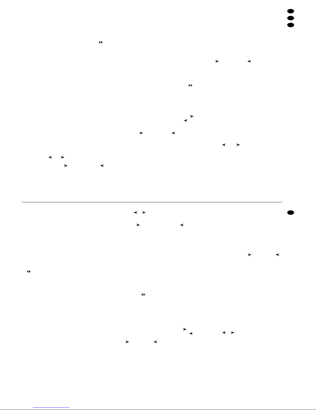
SPEED nur einmal gedrückt, ist nach dem Ablauf
von ca. 13 Minuten automatisch diese maximale
Zeit als T aktzeit eingestellt. Die Takt-LED erlischt.
Hinweis: Wenn die Einstellung über die Taste
TAP SPEED nicht zu funktionieren scheint, kann
es daran liegen, dass die Überblendzeit mit dem
Regler C.F.TIME zu lang eingestellt wurde.
5) Die zweite Displayzeile zeigt „Start? Y/N /AU/ “.
Mit einer der folgenden Tasten wählen, ob die
Sequenz gestartet werden soll und in welchem
Modus:
Taste 11/NO (2): Start abbrechen
Die Sequenz wird nicht gestartet; es kann
eine neue Sequenznummer gewählt werden.
Taste 12/YES (2): zeitgesteuerter Ablauf
Die Sequenz wird zeitgesteuert mit der eingestellten Taktzeit gestartet. Die Taktzeit lässt
sich bei laufender Sequenz ändern.
Blinkt die gelbe T akt-LED während einer Überblendung auf, wird noch kein neuer Sequenzschritt ausgeführt. Die laufende Überblendung
wird erst beendet und mit dem folgenden Aufblinken dann zur nächsten Szene übergeblendet.
Taste BANK/AUDIO (27): audiogest. Ablauf
Die Sequenz wird gestartet und mit Musikimpulsen an der Buchse AUDIO IN (32) synchronisiert oder, wenn die Buchse nicht angeschlossen ist, über das interne Mikrofon (4).
Das Display zeigt „Audio Trig.“ Die Empfindlichkeit mit dem Regler AUDIO SENS. (9) so
einstellen, dass die gelbe Takt-LED im Rhythmus der Musik blinkt. Während einer Überblendung werden die Musikimpulse ignoriert.
Cursor-Taste oder (23): manueller Ablauf
Mit jedem Tastendruck wird die Sequenz
manuell vorwärts ( ) oder rückwärts ( )
Schritt für Schritt weitergeschaltet, z. B. bei
Theateraufführungen, wo ein Szenenwechsel
auf ein Stichwort erfolgen muss. Das Display
zeigt „Manu. Step“.
Wird eine der beiden Tasten während einer
Überblendung gedrückt, so wird diese sofort
beendet. Erst bei nochmaligem Drücken wird
der nächste Schritt ausgeführt.
Nach dem Start einer Sequenz zeigt das Display
die Nummer der laufenden Sequenz, die Nummer des gerade gezeigten Schrittes sowie die
dazugehörige Bank- und Szenennummer [z. B.
„Seq12 St059 10/04“ für Sequenz Nr. 12, aktueller Schritt (step) 59, Szene 4 in Bank 10].
6) Während des Ablaufs einer Sequenz kann nach
dem Drücken der Taste SEQUENCE schon die
nächste wiederzugebende Sequenz gewählt
werden. Wenn die Anzeige „Start? Y/N/AU/ “
erscheint, lässt sich die neue Sequenz mit der
entsprechenden Taste starten. Wird jedoch die
Taste 11/NO gedrückt, zeigt die Anzeige wieder
Sequenz-, Schritt-, Bank- und Szenennummer
der noch laufenden Sequenz.
7) Während eines zeit- oder audiogesteuerten Sequenzablaufs lässt sich vorzeitig mit der Taste
auf die nächste Szene und mit der Taste zurück auf die vorherige Szene wechseln. Dabei
bestimmen die Tasten auch die weitere Laufrichtung vorwärts ( ) oder rückwärts ( ).
8) Während eines zeitgesteuerten oder manuellen
Ablaufs kann mit der T aste BANK/AUDIO direkt in
den audiogesteuerten Ablauf gewechselt werden.
9) Während eines audiogesteuerten oder manuellen Ablaufs kann durch zweimaliges Drücken der
Taste TAPSPEED im gewünschten Takt direkt in
den zeitgesteuerten Ablauf gewechselt werden.
7.2.1 Manuelle Szenenüberblendung
einer Sequenz
Sequenzen, die ohne eigene Überblendzeiten gespeichert wurden, können auch mithilfe der manuellen Überblendung ablaufen. Dazu den Regler
C.F.TIME (7) ganz nach rechts in die Position MAN
drehen; die LED unterhalb des Crossfaders (16)
leuchtet. Den Crossfader nun abwechselnd von
Endposition zu Endposition bewegen. Dabei wird
die Sequenz Schritt für Schritt mit manueller Überblendung zwischen den Szenen durchlaufen. Mit
den Cursor-Tasten (23) lässt sich die Laufrichtung
vorwärts ( ) oder rückwärts ( ) ändern.
Hinweis: Wenn manuelle Überblendung eingestellt
ist, erfolgt die Schrittweiterschaltung bei zeit- oder
audiogesteuertem Ablauf auch nur durch Überblenden mit dem Crossfader.
7.2.2 Sequenzablauf unterbrechen
Um einen zeit- oder audiogesteuerten Ablauf zu
unterbrechen, die Taste HOLD (3) drücken. Eine
laufende Überblendung wird sofort zu Ende geführt
und das Display zeigt „Halted!Cont? Y/N“. Eine der
folgenden T asten betätigen:
12/ YES (2): zum Fortsetzen (continue) derselben
Sequenz
11/ NO (2): zum Beenden der Sequenz; es kann
dann eine andere Sequenz gewählt oder mit der
Taste ESC /SETUP vom Sequenzmodus in den
Direkt-Modus gewechselt werden (die grüne LED
RUN erlischt)
Cursor-Taste oder (23): zum Wechseln auf
manuellen Ablauf
7.2.3 Sequenzablauf beenden
Nach dem letzten Sequenzschritt wird wieder auf
den ersten Schritt gesprungen und so die Sequenz
laufend wiederholt. Um den Ablauf zu beenden, die
Taste SEQUENCE (26) drücken. Es kann dann eine
andere Sequenznummer gewählt werden oder
durch erneutes Drücken der T aste SEQUENCE vom
Sequenzmodus in den Direkt-Modus gewechselt
werden (die grüne LED RUN erlischt).
the first pressing, the yellow rhythm LED lights
up, after the second pressing, it is extinguished.
The time between the two actuations of the button defines the time until the next change of
scene. If the button TAPSPEED is pressed only
once, after approx. 13 minutes of running, this
maximum time is automatically adjusted as the
rhythm time. The rhythm LED is extinguished.
Note: If the adjustment via the button TAP
SPEED does not seem to function, it may be due
to the fact that the crossfading time adjusted with
the control C.F. TIME is too long.
5) The second display line shows “Start? Y/ N /AU /
”. Define with one of the subsequent buttons if
the sequence is to be started and in which mode:
Button 11/NO (2): interrupt start
The sequence is not started; a new sequence
number can be selected.
Button 12/YES (2): time-controlled run
The sequence is started time-controlled with
the adjusted rhythm time. The rhythm time
may be changed while the sequence is running.
If the yellow rhythm LED flashes while crossfading, a new sequence step is not yet made.
The current crossfading is stopped first and
the unit crossfades to the next scene at the
subsequent flashing.
Button BANK/AUDIO (27): audio-controlled run
The sequence is started and synchronized
with music pulses at the jack AUDIO IN (32)
or, if the jack is not connected, via the internal
microphone (4). The display shows “Audio
Trig.”. Adjust the sensitivity with the control
AUDIO SENS. (9) so that the yellow rhythm
LED flashes to the rhythm of the music. While
crossfading, the music pulses are ignored.
Cursor key or (23): manual run
Each time the button is pressed, the sequence
is manually advanced step by step in forward
direction ( ) or backward direction ( ), e.g.
for theatre performances where a change of
scene must be made on cue. The display
shows “Manu.Step”.
If one of the two buttons is pressed while
crossfading, it will stop immediately. By pressing again, the next step is made.
After the start of a sequence the display shows
the number of the current sequence, the number
of the step currently displayed and the corresponding bank number and scene number (e.g.
“Seq12 St059 10/ 04” for sequence No. 12, current step 59, scene 4 in bank 10).
6) While a sequence is running, it is possible to
select the next sequence to be reproduced after
pressing the button SEQUENCE. If the display
“Start? Y/N /AU/ ” is shown, the new sequence
can be started with the corresponding button.
However, if the button 11/NO is pressed, the display again shows the numbers of sequence,
step, bank, and scene of the sequence still running.
7) During a time-controlled or audio-controlled run
of a sequence it is possible to advance to the
next scene before the end with the button and
return to the previous scene with the button .
The buttons determine if the unit continues in forward ( ) or backward ( ) direction.
8) During a time-controlled or manual run it is possible to change directly into the audio-controlled
run with the button BANK/AUDIO.
9) During an audio-controlled or manual run it is
possible to change directly into the time-controlled run by pressing the button TAP SPEED
twice in the desired rhythm.
7.2.1 Manual scene crossfading of a sequence
Sequences which have been memorized without
individual crossfading times may also run by means
of manual crossfading. For this purpose turn the control C.F. TIME (7) fully to the right to position MAN;
the LED below the crossfader (16) lights up. Now
move the crossfader alternately from one end position to the other end position. The sequence is run
step by step with manual crossfading between the
scenes. With the cursor buttons (23) it is possible to
change the direction: forward ( ) or backward ( ).
Note: If manual crossfading has been adjusted, the
steps are only advanced by crossfading with the
crossfader in case of time-controlled run or audiocontrolled run.
7.2.2 Interrupting the sequence run
To interrupt a time-controlled or audio-controlled
run, press the button HOLD (3). A current crossfading is immediately stopped and the display
shows “Halted!Cont? Y/N”. Actuate one of the subsequent buttons:
12/YES (2) to continue the same sequence
11/ NO (2) to stop the sequence; then it is possible to
select another sequence or to change from the
sequence mode into the direct mode with the button ESC/ SETUP (the green LED RUN is extinguished)
Cursor button or (23): to change to manual run
7.2.3 Stopping the sequence run
After the last sequence step the unit goes to the first
step again. Thus, the sequence is repeated continuously. To stop the run, press the button
SEQUENCE (26). Then it is possible to select another sequence number or to change from the
sequence mode into the direct mode by pressing the
button SEQUENCE again (the green LED RUN is
extinguished).
15
GB
D
A
CH
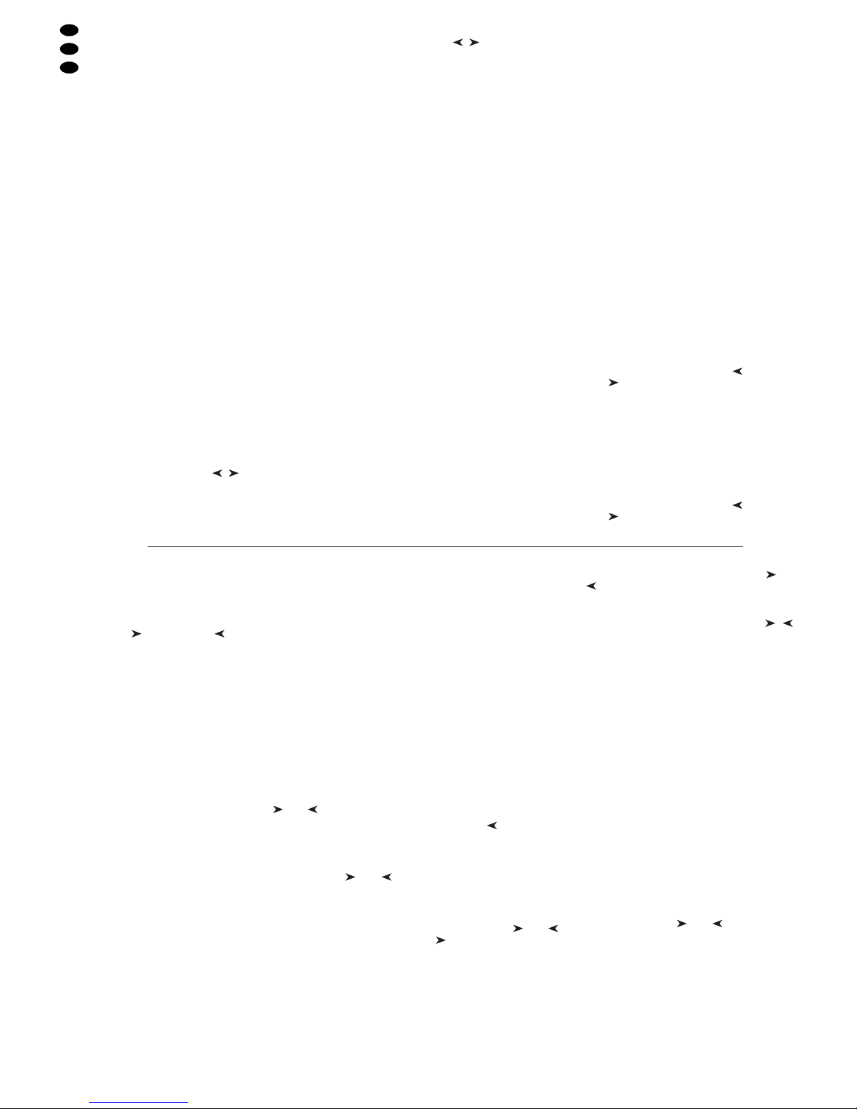
8 Kurzübersicht über die Bedienung
Szene einstellen
1) Steuerkanalgruppe(n) mit Tasten CTRL CHANNEL PAGE [1..12] bis [85..96] wählen.
2) Regler MASTER LEVEL auf Maximalwert stellen.
3) Szene mit den Schiebereglern einstellen (letzter
Wert muss vom Regler „abgeholt“ werden).
4) Eventuell den Steuerhebel MOTION CONTROL
für grobe Voreinstellung aktivieren (mit STICK
CONTROLASSIGN 1/2 und/oder 7/8: LED unterhalb der entsprechenden Schieberegler leuchtet).
Überblenden auf eine andere Einstellung
1) 1. Szene einstellen.
2) Taste HOLD drücken: LED HOLD/ CROSSFADE
leuchtet.
3) 2. Szene einstellen.
4) Mit Regler C.F.TIME Überblendzeit einstellen.
5) Taste HOLD drücken: Überblendung startet –
oder manuell überblenden.
Manuell überblenden
1) Regler C.F.TIME auf Rechtsanschlag drehen: Display: „CFTIME: manu.“, LED MANUAL CROSSFADE leuchtet.
2) Crossfader MANUAL CROSSFADE in eine Endposition bringen.
3) Crossfader zu der anderen Endposition bewegen:
Überblendung läuft. Beim Erreichen der anderen
Endposition ist die Überblendung beendet.
Szene speichern
1) Szene einstellen.
2) Bank wählen mit Tasten , oder Taste BANK
und Zifferntasten [0][1] …[2][0].
3) Taste STORE drücken.
4) Szenentaste drücken [1] …[12].
Szene aufrufen
1) Bank wählen mit Tasten , oder Taste BANK
und Zifferntasten [0][1] …[2][0].
2) Mit Regler C.F.TIME Überblendzeit einstellen.
3) Szenentaste drücken [1] …[12]: Überblendung
startet – oder manuell überblenden.
Flash-Tasten
Funktion „FLASH CHANNEL“
1) Taste FLASH MODE so oft drücken, bis rote LED
FL.CH. leuchtet.
2) Steuerkanalgruppe(n) mit Tasten CTRL CHANNEL PAGE wählen.
3) Flash-Taste (unterhalb der Schieberegler) gedrückt halten.
Funktion „FLASH GROUP“
1) Taste FLASH MODE so oft drücken, bis gelbe
LED FL.GRP. leuchtet.
2) Flash-Taste [1]…[5] gedrückt halten.
Funktion „SHOW VALUE“
1) Taste FLASH MODE so oft drücken, bis grüne
LED SH.VAL. leuchtet.
2) Steuerkanalgruppe mit Taste CTRL CHANNEL
PAGE wählen.
3) Flash-Taste drücken: Display zeigt zugehörigen
Kanalwert an.
Flash-Gruppe programmieren
1) Taste FLASH MODE gedrückt halten und Taste
STORE drücken: LEDs FL.CH. und FL. GRP.
leuchten.
2) Mit Tasten CTRL CHANNEL PAGE und FlashTasten Kanäle anwählen.
3) Taste STORE drücken: LED FL.CH. erlischt,
LED FL.GRP. leuchtet weiter.
4) Flash-Taste [1] … [5] für gewünschten Gruppenspeicher drücken.
Flash-Gruppe ändern
1) Taste FLASH MODE so oft drücken, bis gelbe
LED FL.GRP. leuchtet.
2) Entsprechende Flash-Taste(n) [1] … [5] gedrückt
halten und Taste STORE drücken: LEDs FL.CH.
und FL.GRP. leuchten.
3) Zusätzliche Kanäle anwählen oder angewählte
Kanäle abwählen (mit Tasten CTRL CHANNEL
PAGE und Flash-Tasten).
4) Taste STORE drücken: LED FL.CH. erlischt,
LED FL.GRP. leuchtet weiter.
5) Flash-Taste [1] … [5] für gewünschten Gruppenspeicher drücken.
Ablauf einer Szenensequenz
1) Taste SEQUENCE drücken: Grüne LED RUN
leuchtet.
2) Sequenznummer mit Zifferntasten [0] [1] … [6][0]
wählen.
zeitgesteuert starten
1) Tempo vorgeben mit Regler SEQUENCER
SPEED oder 2 x Taste TAP SPEED drücken.
2) Wenn die gewählte Sequenz nicht vom Typ
„+CFT“ ist (d. h. mit gespeicherten Überblendzeiten), die Überblendzeit mit Regler C.F.TIME einstellen.
3) Zum Starten Taste YES drücken.
4) Zur Richtungsänderung Taste (rückwärts)
oder (vorwärts) drücken.
musikgesteuert starten
1) Taste AUDIO drücken. Anzeige: „Audio Trig.“ Sequenz startet durch das Audiosignal der Buchse
AUDIO IN oder des internen Mikrofons.
2) Empfindlichkeit mit Regler AUDIO SENS. anpassen.
3) Überblendzeit ggf. mit Regler C.F. TIME verringern.
4) Zur Richtungsänderung Taste (rückwärts)
oder (vorwärts) drücken.
manuell starten
1) Wenn die gewählte Sequenz nicht vom Typ
„+CFT“ ist (d. h. mit gespeicherten Überblendzeiten), die Überblendzeit mit Regler C.F.TIME einstellen.
2) Taste (vorwärts) oder (rückwärts) drücken,
um je einen Schritt weiter zu schalten (bei laufender Überblendung wird beim ersten Drücken die
Überblendung beendet, beim zweiten der nächste Schritt aufgerufen).
Ablauf anhalten (bei Zeit- oder Audiosteuerung)
1) Zum Anhalten Taste HOLD drücken.
2) Zum Fortsetzen Taste YES drücken oder zum
Abbrechen T aste NO.
laufende Sequenz durch andere Sequenz ablösen
1) Taste SEQUENCE drücken.
2) Neue Sequenznummer mit Zifferntasten [0] [1]…
[6][0] wählen.
3) Neue Sequenz mit Taste YES, AUDIO, oder
starten.
Ablauf beenden
1) Taste SEQUENCE so oft drücken, bis LED RUN
erlischt.
Sequenz programmieren
1) Taste SEQUENCE drücken: Grüne LED RUN
leuchtet.
2) Taste STORE drücken: Rote LED PRG leuchtet.
3) Sequenznummer mit Zifferntasten [0] [1]… [6][0]
wählen.
4) Bereits programmierte Sequenz ggf. mit Taste
DELETE löschen und mit Taste YES bestätigen.
5) Sequenztyp wählen: Überblendzeit CFT mitspeichern T aste YES, ohne Überblendzeit Taste NO.
6) Bank [0] [1]…[2][0] und Szene [0][1] …[1][2] für
1. Schritt eingeben.
7) Szene mit Taste STORE speichern oder nach
dem Drücken der Taste NO andere Szene anwählen.
8) Bei Sequenztyp „+CFT“ mit Regler C.F.TIME die
Überblendzeit für diesen Schritt einstellen und
mit Taste STORE bestätigen.
9) Weitere Schritte eingeben. Danach mit Taste SEQUENCE die Programmierung beenden und in
den Sequenzablauf-Modus wechseln (grüne
LED RUN leuchtet) oder durch erneutes Drücken
in den Direkt-Modus (grüne LED RUN erlischt).
Sequenz verändern
1) Taste SEQUENCE drücken, dann Taste STORE.
Sequenznummer mit Zifferntasten wählen.
2) Anhängen neuer Schritte: Taste drücken. Eingabe der Szene wie unter „Sequenz programmieren“ ab Bedienschritt 6).
3) Szene eines Schrittes ändern: Schritt mit Taste
oder anwählen. Eingabe der neuen Szene
wie unter „Sequenz programmieren“ ab Bedienschritt 6).
4) Nur Überblendzeit eines Schrittes ändern (bei
Sequenztyp „+CFT“): Schritt mit Taste oder
anwählen. Mit Taste auf die zugehörige Überblendzeit springen. Mit Regler C.F. TIME neue
Überblendzeit einstellen und mit Taste STORE
bestätigen.
5) Sequenzschritt löschen: Schritt mit Taste oder
anwählen. Taste DELETE drücken und be-
stätigen mit Taste YES.
6) Sequenzschritt einfügen: Schritt wählen, vor dem
ein neuer Schritt eingefügt werden soll ( , ).
Taste INSERTdrücken. Eingabe der neuen Szene
wie unter „Sequenz programmieren“ ab Bedienschritt 6).
7) Nach den Änderungen mit Taste SEQUENCE in
den Sequenzablauf-Modus wechseln (grüne LED
RUN leuchtet) oder durch erneutes Drücken in
den Direkt-Modus (grüne LED RUN erlischt).
Steuerkanäle konfigurieren
1) Mit Taste ESC/SETUP Menü aufrufen.
– Menüpunkt „Output Options" zur Änderung der
DMX-Adressenzuordnung und Invertierung
von DMX-Werten
– Menüpunkt „Control Options“ zur Änderung
der Steuerkanaleigenschaften:
1. Master-Abhängigkeit (Master Depend)
2. Überblendfähigkeit (Crossfade)
3. Blackout-Funktion
4. Full/Flash-Funktion
– Menüpunkt „Reset All Opt’s“ zum Zurückset-
zen aller unter „Output Options“ und „Control
Options“ durchgeführten Änderungen auf die
Voreinstellung
2) Menüpunkt mit Taste NO oder YES auswählen.
3) Parameter mit Taste oder anwählen.
4) Einstellung mit Taste NO oder YES ändern oder
numerische Direkteingabe mit den Zifferntasten.
5) Menü durch (mehrfaches) Drücken der Taste
ESC/ SETUP verlassen.
16
D
A
CH
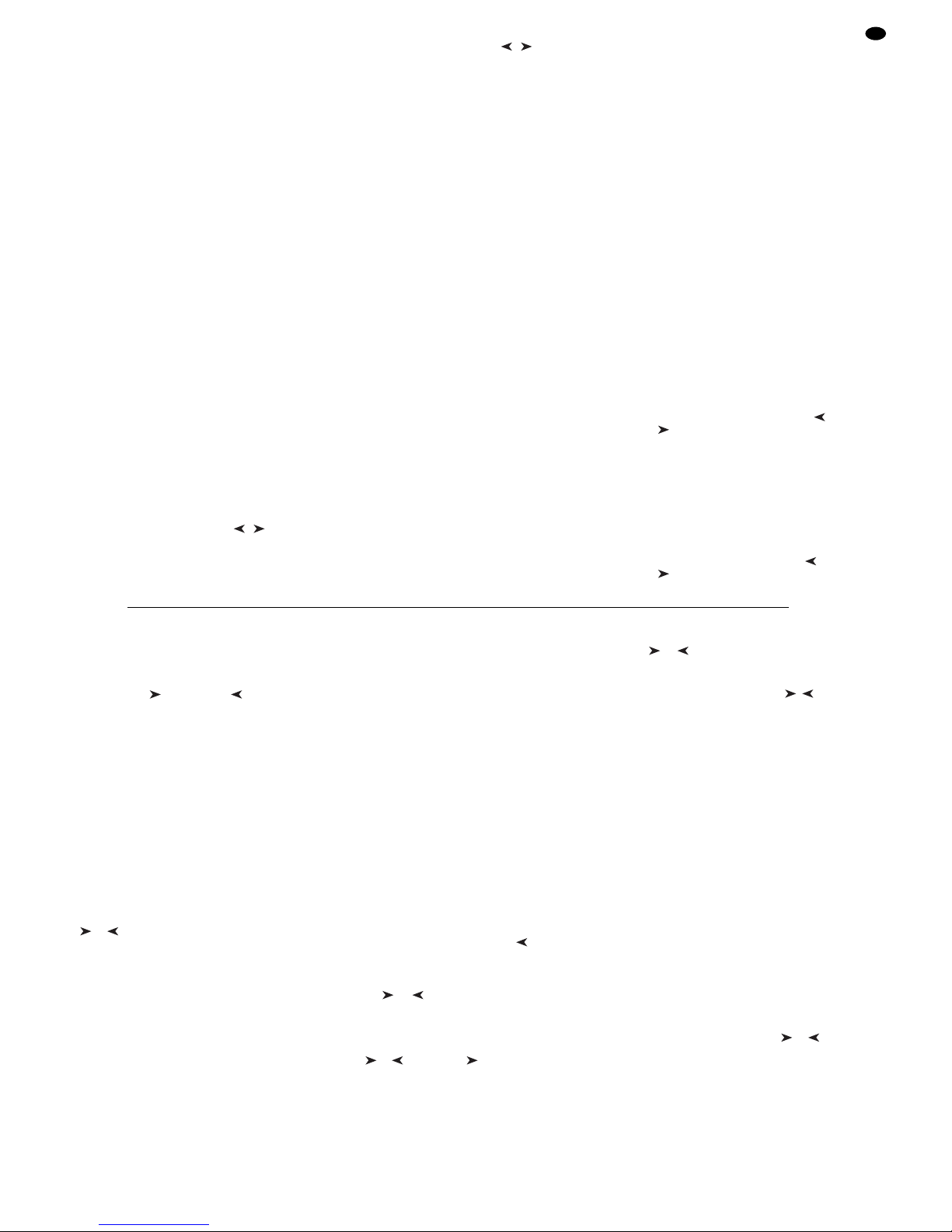
8 Short Overview of the Operation
Adjusting a scene
1) Select the control channel group(s) with buttons
CTRL CHANNELPAGE [1..12] to [85..96].
2) Adjust the fader MASTER LEVEL to maximum
value.
3) Adjust the scene with the sliding controls (last
value must be “fetched” by the fader).
4) If necessary, activate the control lever MOTION
CONTROL for coarse presetting (with STICK
CONTROLASSIGN 1/2 and/or 7/ 8: the LED below the corresponding sliding controls lights up).
Crossfading to another adjustment
1) Adjust the 1st scene.
2) Press button HOLD: LED HOLD /CROSSFADE
lights up.
3) Adjust the 2nd scene.
4) Adjust the crossfading time with the control C.F.
TIME.
5) Press button HOLD: the crossfading starts – or
crossfade manually.
Manual crossfading
1) Turn the control C.F.TIME to the right stop: Display: “CFTIME: manu.”, LED MANUAL CROSSFADE lights up.
2) Set crossfader MANUAL CROSSFADE to an end
position.
3) Move the crossfader to the other end position:
The crossfading starts running. When reaching
the other end position, the crossfading stops.
Memorizing a scene
1) Adjust the scene.
2) Select the bank with buttons , or button
BANK and numerical keys [0] [1]... [2] [0].
3) Press button STORE.
4) Press the button for the scene [1] ...[12].
Calling a scene
1) Select the bank with buttons , or button
BANK and numerical keys [0] [1]... [2] [0].
2) Adjust the crossfading time with control C.F.
TIME.
3) Press the scene button [1] ...[12]: crossfading
starts – or crossfade manually.
Flash buttons
Function “FLASH CHANNEL”
1) Press button FLASH MODE so many times until
the red LED FL.CH. lights up.
2) Select the control channel group(s) with buttons
CTRL CHANNELPAGE.
3) Keep the flash button (below the sliding controls)
pressed.
Function “FLASH GROUP”
1) Press button FLASH MODE so many times until
the yellow LED FL.GRP. lights up.
2) Keep the flash button [1] ...[5] pressed.
Function “SHOW VALUE”
1) Press button FLASH MODE so many times until
the green LED SH.VAL. lights up.
2) Select the control channel group with button
CTRL CHANNELPAGE.
3) Press the flash button: the display shows the corresponding channel value.
Programming a flash group
1) Keep button FLASH MODE pressed and press
button STORE: LEDs FL.CH. and FL. GRP. light
up.
2) Select the channels with buttons CTRL CHANNEL PAGE and the flash buttons.
3) Press button STORE: LED FL.CH. is extinguished, LED FL.GRP. is still illuminated.
4) Press the flash button [1] ... [5] for the desired
group memory.
Changing a flash group
1) Press button FLASH MODE so many times until
the yellow LED FL.GRP. lights up.
2) Keep the corresponding flash button(s) [1] ... [5]
pressed and press button STORE: LEDs FL.CH.
and FL.GRP. light up.
3) Select additional channels or cancel selected
channels (with buttons CTRL CHANNEL PAGE
and the flash buttons).
4) Press button STORE: LED FL.CH. is extinguished, LED FL.GRP. is still illuminated.
5) Press the flash button [1] ... [5] for the desired
group memory.
Run of a scene sequence
1) Press button SEQUENCE: The green LED RUN
lights up.
2) Select the sequence number with the numerical
keys [0] [1]... [6] [0].
Time-controlled start
1) Specify the speed with control SEQUENCER
SPEED or press button TAPSPEED twice.
2) If the selected sequence is not of type “+CF T”
(i. e. with memorized crossfading times), adjust
the crossfading time with control C.F.TIME.
3) To start, press button YES.
4) To change the direction, press button (forward) or (backward).
Music-controlled start
1) Press button AUDIO. Display: “Audio Trig.” The
sequence starts by the audio signal of the jack
AUDIO IN or of the internal microphone.
2) Match the sensitivity with control AUDIO SENS.
3) If necessary, reduce the crossfading time with
control C.F.TIME.
4) To change the direction, press button (backward) or (forward).
Manual start
1) If the selected sequence is not of type “+CF T”
(i. e. with memorized crossfading times), adjust
the crossfading time with control C.F.TIME.
2) Press button (forward) or (backward) to
advance one step in each case (with current
crossfading, the crossfading is stopped with the
first pressing, with the second pressing the next
step is called).
Holding the run (in case of time control or audio control)
1) To hold, press button HOLD.
2) To continue, press button YES or to interrupt,
press button NO.
Replacing a running sequence by another sequence
1) Press button SEQUENCE.
2) Select a new sequence number with the numerical keys [0] [1]... [6] [0].
3) Start the new sequence with button YES, AUDIO,
or .
Stopping the run
1) Press button SEQUENCE so many times until
LED RUN is extinguished.
Programming a sequence
1) Press button SEQUENCE: The green LED RUN
lights up.
2) Press button STORE: The red LED PRG lights
up.
3) Select the sequence number with the numerical
keys [0] [1]... [6] [0].
4) Delete the sequence already programmed with
button DELETE, if necessary, and confirm with
button YES.
5) Select the sequence type: to memorize with the
crossfading time CFT button YES, without crossfading time button NO.
6) Enter bank [0] [1] ...[2] [0] and scene [0] [1]... [1]
[2] for the first step.
7) Memorize the scene with button STORE or select
another scene after pressing button NO.
8) In case of sequence type “+CFT” adjust the
crossfading time for this step with control C.F.
TIME and confirm with button STORE.
9) Enter further steps. Then stop the programming
with button SEQUENCE and change into the
sequence running mode (green LED RUN lights
up) or into the direct mode by pressing again
(green LED RUN is extinguished).
Changing the sequence
1) Press button SEQUENCE, then button STORE.
Select the sequence number with the numerical
keys.
2) Attach new steps: Press button . Enter the
scene as under “Programming a sequence” as
from operating step 6).
3) Change the scene of a step: Select the step with
button or . Enter the new scene as under
“Programming a sequence” as from operating
step 6).
4) Change only the crossfading time of a step (for
sequence type “+CFT”): Select the step with button or . With button go to the corresponding crossfading time. Adjust the new crossfading
time with control C.F.TIME and confirm with button STORE.
5) Delete the sequence step: Select the step with
button or . Press button DELETE and confirm with button YES.
6) Insert a sequence step: Select the step before
which a new step is to be inserted ( , ). Press
button INSERT. Enter the new scene as under
“Programming a sequence” as from operating
step 6).
7) After the modifications, change with button
SEQUENCE into the sequence running mode
(green LED RUN lights up) or into the direct
mode by pressing again (green LED RUN is
extinguished).
Configuring control channels
1) Call the menu with button ESC/SETUP.
– Menu item “Output Options” to change the
DMX address assignment and inversion of
DMX values
– Menu item “Control Options” to change the
control channel characteristics:
1. Master Depend
2. Crossfade
3. Blackout function
4. Full/flash function
– Menu item “Reset All Opt’s” to reset all chang-
es made under “Output Options” and “Control
Options” to the presetting
2) Select the menu item with button NO or YES.
3) Select the parameters with button or .
4) Change the adjustment with button NO or YES or
numerical direct input with the numerical keys.
5) Exit the menu by (repeated) pressing of button
ESC/SETUP.
17
GB
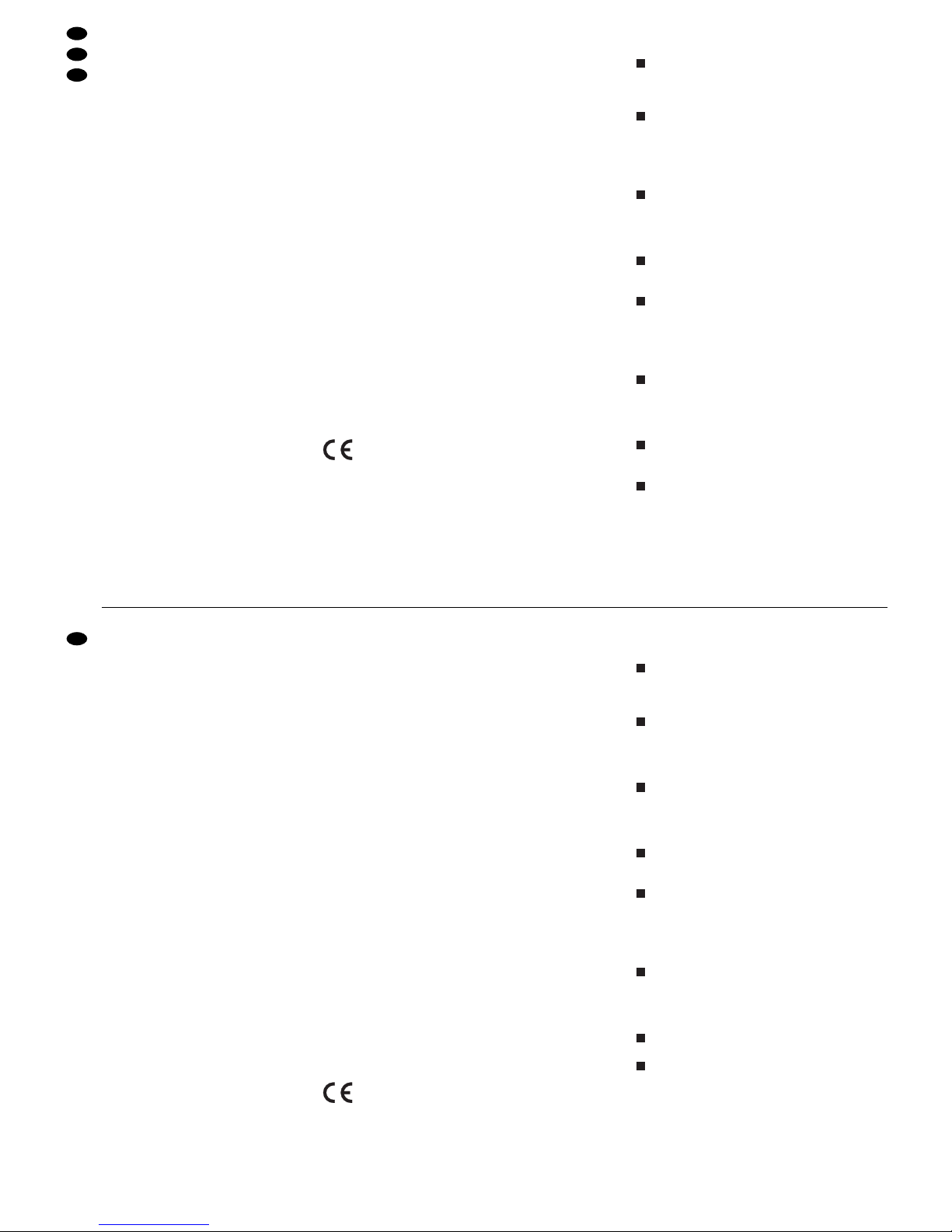
9Technische Daten
DMX-Ausgang: . . . . . . . . . XLR, 3- und 5-polig
Pin 1 = Masse
Pin 2 = DMX-Signal
Pin 3 = DMX-Signal +
Pin 4 und 5 = frei
Audio-Eingang: . . . . . . . . . 0,1 –2 V/22kΩ, stereo,
6,3-mm-Klinke
Musiksteuerung: . . . . . . . . über internes Mikrofon
oder Buchse AUDIO IN
zuweisbare DMX-Adressen: 001– 144
Steuerkanäle: . . . . . . . . . . . 96
speicherbare Szenen: . . . . 240 (je 12 in 20 Spei-
cherbanken)
speicherbare Sequenzen: . 60 mit max.
120 Schritten
Überblendzeit: . . . . . . . . . . 0– 25,4s oder manu-
elle Überblendung mit
Crossfader
Display: . . . . . . . . . . . . . . . LCD, alphanumerisch,
beleuchtet,
2 Zeilen à 16 Zeichen
Stromversorgung: . . . . . . . 230 V~/50 Hz/10VA
Einsatztemperatur: . . . . . . . 0– 40°C
Abmessungen: . . . . . . . . . . 482 x 178 x 85 mm,
4 HE (Höheneinheiten)
Gewicht: . . . . . . . . . . . . . . . 3 kg
Änderungen vorbehalten.
Übersicht der Konfigurationsmöglichkeiten
Erläuterungen zur Abb. 7 auf Seite 19.
Die 96 Steuerkanäle sind in 8 Gruppen unterteilt.
Die Gruppen können einzeln oder auch zu mehreren angewählt werden. Dadurch lassen sich
mehrere Geräte zeitweilig gemeinsam steuern.
Die Optionen Masterabhängigkeit (M), Überblendbarkeit mit Zwischenwerten (C), Blackout
(B) und Full On/Flash (F) sind für jeden Steuerkanal einzeln deaktivierbar (N), wenn die Funktion nicht sinnvoll ist. Voreingestellt ist, dass die
Option aktiviert ist (Y).
Der Steuerhebel MOTION CONTROL lässt sich
für die Kanäle 1/2 und/ oder 7/ 8 einschalten. Je
nach aktivierter Steuerkanalgruppe werden darüber auch die Kanäle 13/ 14 bzw. 19/ 20, 25/ 26
bzw. 31/32 usw. gesteuert.
Ein Vertauschen von Steuerkanälen erspart das
Umstecken von Anschlüssen an schwer zugänglichen Stellen.
Fehlerhafte oder in einer Szene störende Beleuchtungskörper können aus der Steuerung herausgenommen werden, indem die DMX-Adresse
dem Steuerkanal 0 zugeordnet wird. Es wird
dann permanent der Wert Null ausgegeben oder
der Wert 255 bei Invertierung (invers = Y).
Mehrere DMX-Adressen können demselben
Steuerkanal zugeordnet und deren Ausgabewerte
dabei individuell invertiert werden. Dadurch lassen
sich z.B. Scanner synchron steuern, bei Invertierung eines Ausgangs auch spiegelsymmetrisch.
Die Funktionen verschiedener DMX-Geräte lassen sich zur besseren Übersicht in eine einheitliche Reihenfolge ordnen.
Obwohl nur 96 Steuerkanäle zur Verfügung stehen können 144 DMX-Adressen angesprochen
werden, wenn diese abwechselnd oder mehrere
parallel den Steuerkanälen zugeordnet werden.
8
7654321
9 Specifications
DMX output: . . . . . . . . . . . . XLR,3-pole and 5-pole
pin 1 = ground
pin 2 = DMX signal
pin 3 = DMX signal +
pins 4 and 5: not
connected
Audio input: . . . . . . . . . . . . 0.1 –2V/22kΩ,
stereo, 6.3mm jack
Music control: . . . . . . . . . . . via internal microphone
or jack AUDIO IN
DMX addresses to
be assigned: . . . . . . . . . . . 001–144
Control channels: . . . . . . . . 96
Scenes to be memorized: . 240 (12 each in
20 memory banks)
Sequences to
be memorized: . . . . . . . . . . 60 with max.
120 steps
Crossfading time: . . . . . . . . 0 –25.4s or manual
crossfading
with crossfader
Display: . . . . . . . . . . . . . . . LCD, alphanumeric,
illuminated,
2 lines of 16 characters each
Power supply: . . . . . . . . . . 230 V~/50 Hz/10VA
Ambient temperature: . . . . 0 –40 °C
Dimensions: . . . . . . . . . . . . 482 x 178 x 85mm,
4 rack spaces
Weight: . . . . . . . . . . . . . . . . 3kg
Subject to change.
Overview of the Configuration Possibilities
Explanations to fig. 7 on page 19.
The 96 control channels are subdivided into
8 groups. Individual groups or several groups can
be selected. Thus, it is possible to control several
units in common for a time.
The options master depend (M), capability of
crossfading with interim values (C ), blackout (B),
and Full On/ Flash (F) can individually be deactivated for each control channel (N) if the function
is not useful. Activation of the option is preset (Y).
The control lever MOTION CONTROL can be
switched on for the channels 1/2 and/or 7/8.
Depending on the activated control channel
group also the channels 13/14 or 19 / 20, 25 / 26
or 31/32 etc. are controlled via this lever.
By exchanging control channels, it is not necessary to rearrange connections at places of difficult access.
Illumination elements which are defective or may
interfere in a scene can be taken out of the control by assigning the DMX address to the control
channel 0. Then the value 0 is permanently sent
to the output or the value 255 in case of inversion
(inverse = Y).
Several DMX addresses can be assigned to the
same control channel and their output values can
be inverted individually. Thus, e.g. scanners can
be controlled synchronously, in case one output
is inverted, even in a mirror symmetry.
The functions of different DMX units can be
arranged in uniform order for a better overview.
Although only 96 control channels are available,
144 DMX addresses may be approached if they
are assigned to the control channels alternately
or several addresses in parallel
876
5
432
1
18
GB
D
A
CH
Diese Bedienungsanleitung ist urheberrechtlich für MONACOR®INTERNATIONAL GmbH & Co. KG
geschützt. Eine Reproduktion für eigene kommerzielle Zwecke – auch auszugsweise – ist untersagt.
All rights reserved by MONACOR
®
INTERNATIONAL GmbH & Co. KG. No part of this instruction manual
may be reproduced in any form or by any means for any commercial use.
 Loading...