

IMG STAGE LINE DJP-400/SI Instruction Manual
BEDIENUNGSANLEITUNG • INSTRUCTION MANUAL
MODE D’EMPLOI • ISTRUZIONI PER L’USO • GEBRUIKSAANWIJZING • CONSEJOS DE SEGURIDAD
SIKKERHEDSOPLYSNINGER • SÄKERHETSFÖRESKRIFTER • TURVALLISUUDESTA
PROFESSIONELLER DJ-PLATTENSPIELER
PROFESSIONAL DJ TURNTABLE
PLATINE DISQUE DJ PROFESSIONNELLE
GIRADISCHI DJ PROFESSIONALE
DJP-400/SI Best.-Nr. 21.1850
DJP-40
Digital turntable with a/d converter and master tempo
➁ ➂ ➃ ➄➀
Sensationell, das Flaggschiff der Turntable-Serie von
IMG Stage Line: der Digital-Plattenspieler DJP-400/SI.
Mastertempo – die Innovation für Turntables liegt
hinter einem unscheinbaren Schaltknopf verborgen.
Digital-Ausgang, Line/Phono-Ausgänge, Display für
Pitch-Einstellungen und Beatcounts gehören zum 14 kg
schweren High-Torque-Player ebenso dazu wie der
regelbare Brake mit zwei Easy-Touch-Tastern.
Sensational, the flagship of the turntable series from
IMG Stage Line: the digital turntable DJP–400/SI.
Master tempo: the innovation for turntables is concealed behind an inconspicuous push button. Digital
output, line/phono outputs, display for pitch adjustments and beat counts are part of the 14 kg heavy high
torque player as well as the adjustable brake with two
easy-touch momentary push-buttons.
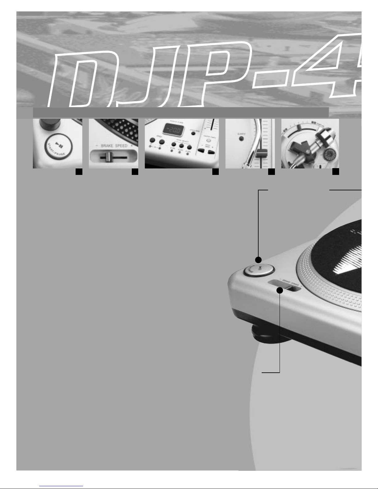
➀
Doppelter Start-Button
Immer an der richtigen Stelle
die ergonomisch platzierten
Easy-Touch-Taster
Dual start button
Always at the right place,
these ergonomically placed
easy-touch momentary
push-buttons
Brake Speed
Die regelbare Bremskraft führt zu
optimal dosierten Effekten
Brake speed
The adjustable brake power leads
to effects at a perfect dose
➁
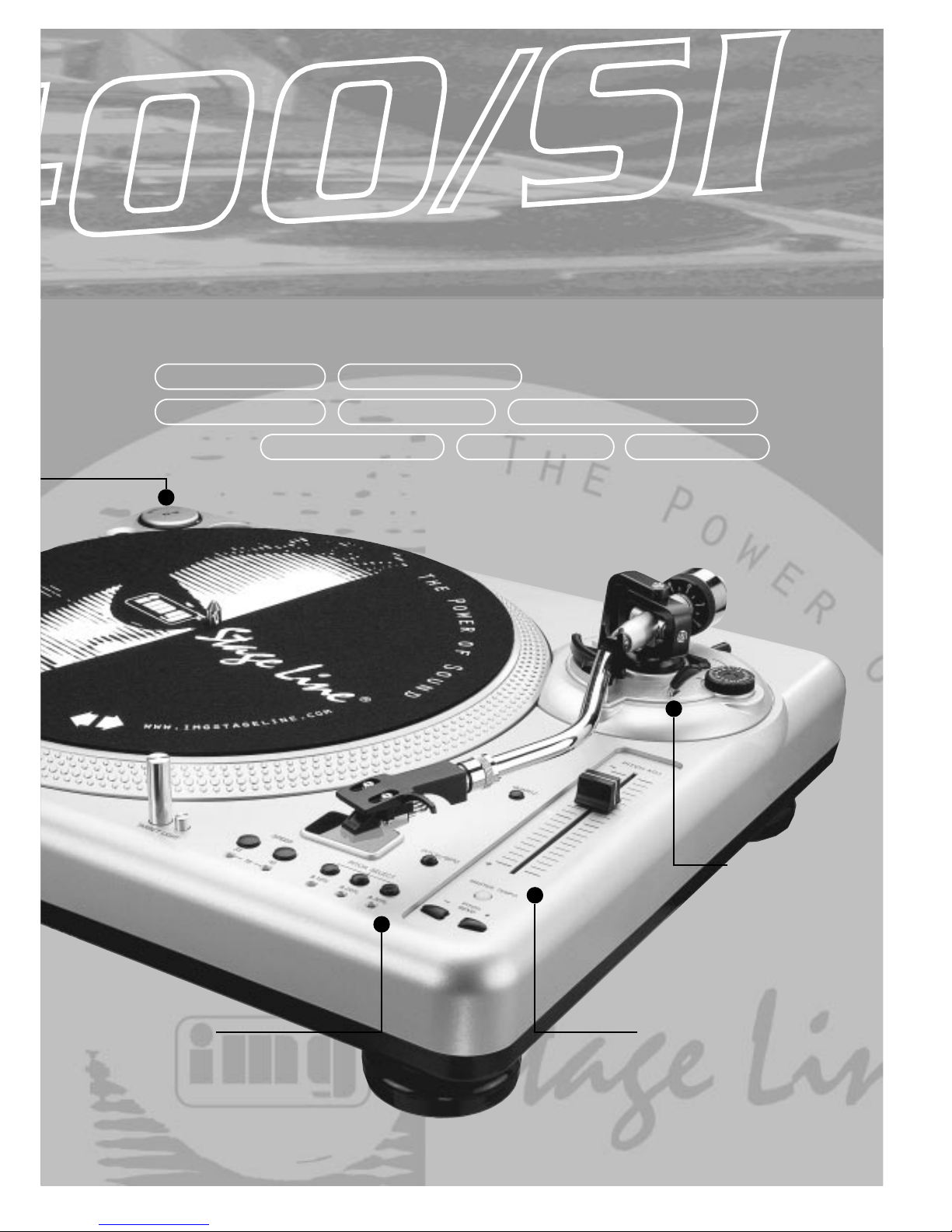
a/d converter master tempo
beat counter high-torque
phono preamp
brake speed control
reverse play pitch bend
Geschwindigkeitsregelung
Mastertempo, 3 Pitch-Einstellungen,
Pitch-Bend und 3 Geschwindigkeiten
Pitch control
Master tempo, 3 pitch adjustments,
pitch bending, and 3 speeds
Tonarmlager
Passgenaue
Höhenjustierung
des Tonarms
Pick-up arm
Exact height
adjustment of
the pick-up arm
➃
➄
➂
➀
Quarzsteuerung
Direktantrieb mit zu- oder
abschaltbarer Quarzsteuerung
Quartz control
Direct drive with quartz
control, which can be
switched on or off

4
wwwwww..iimmggssttaaggeelliinnee..ccoomm
Bevor Sie einschalten ...
Wir wünschen Ihnen viel Spaß mit Ihrem neuen Gerät
von „img Stage Line“. Dabei soll Ihnen diese Bedienungsanleitung helfen, alle Funktionsmöglichkeiten
kennenzulernen. Die Beachtung der Anleitung vermeidet
außerdem Fehlbedienungen und schützt Sie und Ihr
Gerät vor eventuellen Schäden durch unsachgemäßen
Gebrauch.
Den deutschen Text finden Sie auf den Seiten 6 – 11.
Before you switch on ...
We wish you much pleasure with your new unit by “img
Stage Line”. With these operating instructions you will be
able to get to know all functions of the unit. By following
these instructions false operations will be avoided, and
possible damage to you and your unit due to improper
use will be prevented.
You will find the English text on the pages 6–11.
D
A
CH
GB
Avant toute mise en service ...
Nous vous remercions d’avoir choisi un appareil “img
Stage Line” et vous souhaitons beaucoup de plaisir à
l’utiliser. Cette notice a pour objectif de vous aider à
mieux connaître les multiples facettes de l’appareil et à
vous éviter toute mauvaise manipulation.
La version française se trouve pages 12–17.
Prima di accendere ...
Vi auguriamo buon divertimento con il Vostro nuovo apparecchio “img Stage Line”. Le istruzioni per l’uso Vi possono aiutare a conoscere tutte le possibili funzioni. E
rispettando quanto spiegato nelle istruzioni, evitate di
commettere degli errori, e così proteggete Voi stessi, ma
anche l’apparecchio, da eventuali rischi per uso improprio.
Il testo italiano lo potete trovare alle pagine 12–17.
F
B
CH
I
Voordat u inschakelt ...
Wij wensen u veel plezier met uw nieuw toestel van “img
Stage Line”. Met behulp van bijgaande gebruiksaanwijzing zal u alle functiemogelijkheden leren kennen.
Door deze instructies op te volgen zal een slechte werking vermeden worden, en zal een eventueel letsel aan
uzelf en schade aan uw toestel tengevolge van onzorgvuldig gebruik worden voorkomen.
U vindt de nederlandstalige tekst op de pagina’s 18–23.
Antes de cualquier instalación ...
Tenemos de agradecerle el haber adquirido un aparato
“img Stage Line” y le deseamos un agradable uso. Este
manual quiere ayudarle a conocer las multiples facetas
de este aparato. La observación de las instrucciones
evita operaciones erróneas y protege Vd. y vuestro aparato contra todo daño posible por cualquier uso inadecuado.
La versión española se encuentra en las páginas 18–23.
NL
B
E
Inden De tænder for apparatet ...
Vi ønsker Dem god fornøjelse med Deres nye “img Stage
Line” apparat. Læs oplysningerne for en sikker brug af apparatet før ibrugtagning. Følg sikkerhedsoplysningerne for
at undgå forkert betjening og for at beskytte Dem og
Deres apparat mod skade på grund af forkert brug.
Sikkerhedsoplysningerne finder De på side 24.
Förskrift
Vi önskar dig mycket nöje med din nya enhet från “img
Stage Line”. Läs gärna säkerhetsinstruktionerna innan
du använder enheten. Genom att följa säkerhetsinstruktionerna kan många problem undvikas, vilket annars kan
skada enheten.
Du finner säkerhetsinstruktionerna på sidan 24.
DK
S
Ennen virran kytkemistä…
Toivomme, että uusi “img Stage Line”-laitteesi tuo sinulle
paljon iloa ja hyötyä. Ole hyvä ja lue käyttöohjeet ennen
laitteen käyttöönottoa. Luettuasi käyttöohjeet voit käyttää laitetta turvallisesti ja vältyt laitteen väärinkäytöltä.
Käyttöohjeet löydät sivulta 24.
FIN
5
PITCH / BPM
PITCH % & BPM
DJP-400/SI QUARTZ-CONTROLLED DIRECT DRIVE
ON
OFF
POWER
REVERSE
– BRAKE SPEED +
SPEED PITCH SELECT
33 45
78
±10% ±20% ±30%
TARGET LIGHT
PITCH
BEND
–
+
QUARTZ
–
+
PITCH ADJ.
1
2
3
4
5
0
h
e
i
g
h
t
a
d
j
.
mm
6
Lock
A
N
T
I
-
S
K
A
T
I
N
G
1
0
2
3
4
5
6
7
PITCH
BEND
–+
S
T
A
R
T
/
P
A
U
S
E
S
T
A
R
T
/
P
A
U
S
E
MASTER TEMPO
REMOTE
START/STOP
RL
PHONO LINE DIGITAL
OUT
0
5
1
2
6
3
0
5
1
2
6
3
24 25 26 27 28
17 18 19 20 21 22 23
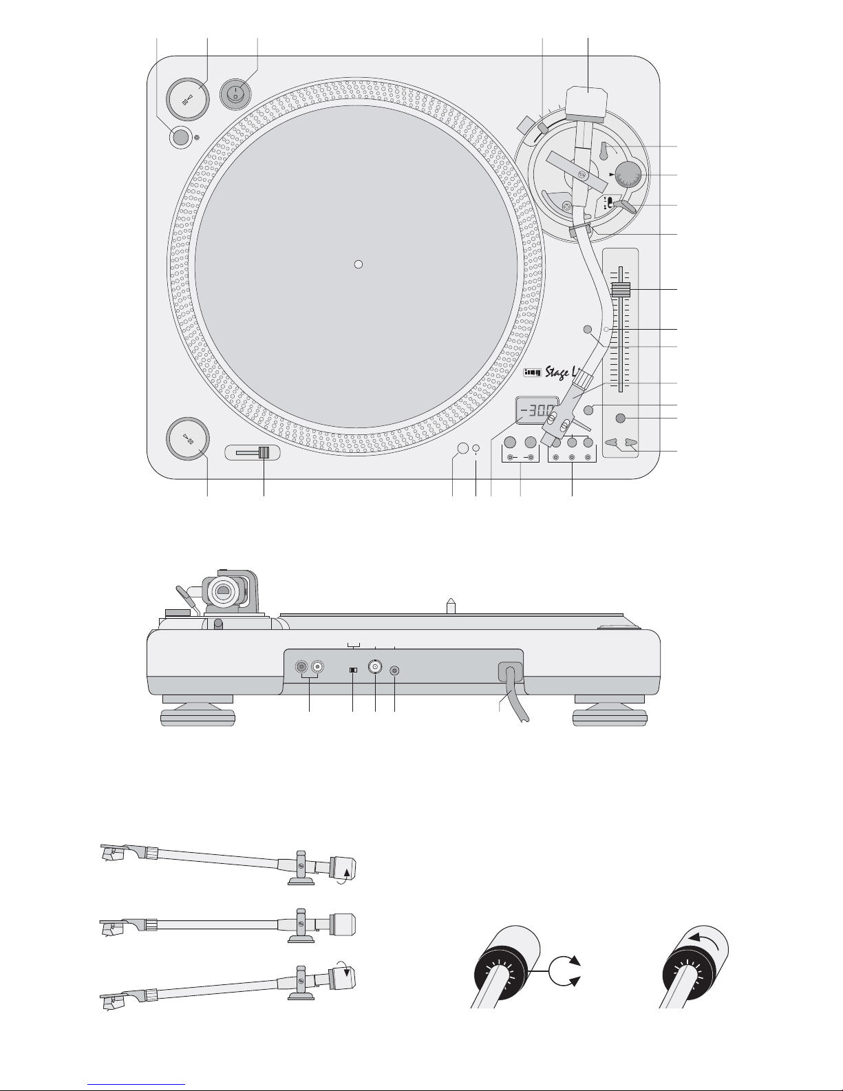
➀
Tonarm ausbalancieren
Tone arm balance ➂
Auflagegewicht einstellen
Stylus pressure adjustment ➄
➁
6
123 45
7
8
9
10
11
12
14
16
15
13
Skalenring
Scale ring ➃

Bitte klappen Sie die Seite 5 heraus. Sie sehen
dann immer die beschriebenen Bedienelemente
und Anschlüsse.
Inhalt
1 Übersicht der Bedienelemente und
Anschlüsse . . . . . . . . . . . . . . . . . . . . . . . . . 6
1.1 Bedienelemente . . . . . . . . . . . . . . . . . . . . . . 6
1.2 Anschlüsse . . . . . . . . . . . . . . . . . . . . . . . . . . 7
2 Hinweise für den sicheren Gebrauch . . . . 7
3 Einsatzmöglichkeiten . . . . . . . . . . . . . . . . . 7
4 Montage und Grundeinstellungen . . . . . .7
4.1 Plattenteller und Systemträger montieren . . 7
4.2 Gegengewicht für den Tonarm montieren . . .7
4.3 Auflagegewicht einstellen . . . . . . . . . . . . . . . 7
4.4 Antiskating einstellen . . . . . . . . . . . . . . . . . . 8
4.5 Höhe des Tonarms einstellen . . . . . . . . . . . . 8
5 Plattenspieler anschließen . . . . . . . . . . . .8
6 Bedienung . . . . . . . . . . . . . . . . . . . . . . . . . . 8
6.1 Schallplatte abspielen . . . . . . . . . . . . . . . . . . 8
6.2 Beatcounter . . . . . . . . . . . . . . . . . . . . . . . . . 8
6.3 Geschwindigkeit mit oder ohne Tonhöhenverschiebung verändern/
Anzahl der Taktschläge verändern . . . . . . . . 9
6.4 Umschalten Vor-/Rücklauf . . . . . . . . . . . . . . 9
6.5 Takt zwischen 2 Musikstücken angleichen . . 9
6.6 Fernsteuern der Funktion „Start/Stopp“ . . . . 9
7 Zubehör . . . . . . . . . . . . . . . . . . . . . . . . . . . . 9
7.1 Ersatz-Tonabnehmersystem und -Nadel . . . 9
7.2 Ersatz-Systemträger . . . . . . . . . . . . . . . . . . .9
7.3 Filzmatte zum „Scratchen“ . . . . . . . . . . . . . 10
8Wartung . . . . . . . . . . . . . . . . . . . . . . . . . . . 10
8.1 Pflege . . . . . . . . . . . . . . . . . . . . . . . . . . . . . 10
8.2 Transport . . . . . . . . . . . . . . . . . . . . . . . . . . 10
9Technische Daten . . . . . . . . . . . . . . . . . . . 10
10 Erklärung der Fachbegriffe . . . . . . . . . . .11
1 Übersicht der Bedienelemente und
Anschlüsse
1.1 Bedienelemente (Abb. 1)
1 Taste REVERSE zum Umschalten zwischen
Vor- und Rückwärtslauf
2 Start/Pause-Taste [wie Taste (17)]
3 Ein-/Ausschalter POWER
4 Einsteller für die Höhe des Tonarms
5 Gegengewicht für den Tonarm
6 Arretierhebel für die Höheneinstellung
7 Drehknopf für die Antiskating-Einstellung
8 Hebel für den Tonarm-Lift
9 Verriegelungshebel für den Tonarm
10 Schieberegler PITCH ADJ. zum Ändern der Ge-
schwindigkeit (max. ±30%)
Hinweis: Nach dem Einschalten läuft der Plattenspieler exakt mit Standardgeschwindigkeit
[Grundeinstellung; grüne LED (11) leuchtet]. Der
Regler PITCH ADJ. ist dann ohne Funktion. Zum
Aktivieren des Reglers die Taste QUARTZ (12)
drücken [grüne LED (11) erlischt].
11 LED zur Anzeige der Standardgeschwindigkeit;
leuchtet nach dem Einschalten (Grundeinstellung)
12 Taste QUARTZ zum Umschalten zwischen
a der Standardgeschwindigkeit – grüne LED
(11) leuchtet (Grundeinstellung)
b der mit dem Schieberegler PITCH ADJ. (10)
eingestellten Geschwindigkeit – grüne LED
aus
13 Systemträger
14 Taste PITCH/BPM zum Umschalten der Digi-
talanzeige (21) zwischen
a Anzeige der Taktschläge pro Minute (BPM =
Beats Per Minute) über den automatischen
Beatcounter (Grundeinstellung)
b Anzeige der Abweichung von der Standard-
geschwindigkeit in %
15 Taste MASTER TEMPO für konstante Tonhöhe;
wurde die T aste betätigt (Taste leuchtet), bleibt bei
Veränderung der Abspielgeschwindigkeit mit dem
Regler PITCH ADJ. (10) und den Tasten PITCH
BEND (16) die Tonhöhe konstant
Hinweise:
Die Funktion lässt sich nur einschalten, wenn der
Regler PITCH ADJ. mit der Taste QUARTZ (12)
aktiviert wurde [grüne LED (11) aus].
Steht der Schalter PHONO/LINE (25) in der
Position PHONO, ist diese Funktion nicht über
die Cinch-Buchsen (24) wirksam.
16 Tasten PITCH BEND +und
-
zur T aktanpassung
zweier Musikstücke;
solange eine der Taste gedrückt gehalten wird,
ist die Geschwindigkeit niedriger bzw. höher
17 Start/Pause-Taste [wie Taste (2)]
18 Schieberegler BRAKE SPEED zum Einstellen
der Geschwindigkeit, mit der der Plattenteller
beim Stoppen abgebremst werden soll
19 Beleuchtung für die Abtastnadel
20 Einschaltknopf für die Nadelbeleuchtung (19)
21 Digitalanzeige, Funktion siehe Position 14
22 Tasten SPEEDzur Wahl der Geschwindigkeit
für 33
1
/3 U/min die linke Taste „33“ drücken – die
LED unter der T aste leuchtet (Grundeinstellung)
für 45U/min die rechte Taste „45“ drücken – die
LED unter der Taste leuchtet
für 78U/min die Tasten „33“ und „45“ gleichzeitig
drücken – die LEDs unter den Tasten leuchten
23 Tasten PITCH SELECT zur Auswahl des Ge-
schwindigkeitseinstellbereiches (10%, 20% oder
30 %) für den Schieberegler PITCH ADJ. (10)
und für die Tasten PITCH BEND (16)
Please unfold page 5. Then you can always see
the operating elements and connections described.
Contents
1 Operating Elements and Connections . . . 6
1.1 Operating elements . . . . . . . . . . . . . . . . . . . 6
1.2 Connections . . . . . . . . . . . . . . . . . . . . . . . . . 7
2 Safety Notes . . . . . . . . . . . . . . . . . . . . . . . . 7
3 Possibilities of Application . . . . . . . . . . . . 7
4 Assembly and Basic Settings . . . . . . . . . . 7
4.1 Mounting the turntable platter
and the headshell . . . . . . . . . . . . . . . . . . . . . 7
4.2 Mounting the counterweight
for the tone arm . . . . . . . . . . . . . . . . . . . . . . 7
4.3 Adjusting the stylus pressure . . . . . . . . . . . . 7
4.4 Adjusting the antiskating facility . . . . . . . . . . 8
4.5 Adjusting the height of the tone arm . . . . . . .8
5 Connecting the Turntable . . . . . . . . . . . . . 8
6 Operation . . . . . . . . . . . . . . . . . . . . . . . . . . . 8
6.1 Playing a record . . . . . . . . . . . . . . . . . . . . . . 8
6.2 Beat counter . . . . . . . . . . . . . . . . . . . . . . . . . 8
6.3 Changing the speed with or without changing
the pitch/changing the number of beats . . . . 9
6.4 Switching of forward/reverse run . . . . . . . . . 9
6.5 Matching the beat between 2 music pieces . 9
6.6 Remote control of the function “Start/Stop” . 9
7 Accessories . . . . . . . . . . . . . . . . . . . . . . . . 9
7.1 Replacement phono cartridge system
and stylus . . . . . . . . . . . . . . . . . . . . . . . . . . . 9
7.2 Replacement headshell . . . . . . . . . . . . . . . . 9
7.3 Felt slipmat for “scratching” . . . . . . . . . . . . . 9
8 Maintenance . . . . . . . . . . . . . . . . . . . . . . . 10
8.1 Cleaning . . . . . . . . . . . . . . . . . . . . . . . . . . . 10
8.2 Transportation . . . . . . . . . . . . . . . . . . . . . . . 10
9 Specifications . . . . . . . . . . . . . . . . . . . . . . 10
10 Explanation of the Technical Terms . . . . 11
1 Operating Elements and Connections
1.1 Operating elements (fig. 1)
1 Button REVERSE to switch between forward
and reverse run
2 Start/pause button [like button (17)]
3 POWER switch
4 Height adjuster for the tone arm
5 Counterweight for the tone arm
6 Locking lever for the height adjustment
7 Rotary knob for the antiskating adjustment
8 Lever for the tone arm lift
9 Locking lever for the tone arm
10 Sliding control PITCH ADJ. to change the pitch
(max. ±30%)
Note: After switching on, the turntable plays
exactly at standard speed [basic setting; green
LED (11) lights up]. The control PITCH ADJ. has
no function. To activate the control, press button
QUARTZ (12) [green LED (11) is extinguished].
11 LED to indicate the standard speed;
lights up after switching on (basic setting)
12 Button QUARTZ to switch between
a the standard speed – green LED (11) lights up
(basic setting)
b the speed adjusted with the sliding control
PITCH ADJ. (10) – green LED extinguishes
13 Headshell
14 Button PITCH / BPM to switch the digital display
(21) between
a display of number of beats per minute (BPM)
via the automatic beat counter (basic setting)
b display of the deviation from the standard
speed in %
15 Button MASTER TEMPO for a constant pitch;
if the button was actuated (button lights up) the
pitch remains constant if the playing speed was
changed with the control PITCH ADJ. (10) and
buttons PITCH BEND (16)
Notes:
The function can only be switched on if control
PITCH ADJ. was activated with button QUARTZ
(12) [green LED (11) extinguished].
If switch PHONO/LINE (25) is in position
PHONO, this function is not effective via the
phono jacks (24)
16 Buttons PITCH BEND + and – for beat matching
of two music pieces;
as long as one of the buttons is kept pressed, the
speed is lower or higher
17 Start/pause button [like button (2)]
18 Sliding control BRAKE SPEED to adjust the
speed by which the turntable platter is braked
while stopping
19 Illumination for the stylus
20 Button to switch on the stylus illumination (19)
21 Digital display, function see item 14
22 Buttons SPEED to select the speed
for 33
1
/3 rpm press the left button “33” – the LED
below the button lights up (basic setting)
for 45 rpm press the right button “45” – the LED
below the button lights up
for 78rpm press the buttons “33” and “45” at the
same time – the LEDs below the buttons light
up
23 Buttons PITCH SELECT to select the adjusting
range for the speed (10%, 20%, or 30%) for the
sliding control PITCH ADJ. (10) and for the buttons PITCH BEND (16)
6
GB
D
A
CH

1.2 Anschlüsse (Abb. 2)
24 analoger Audioausgang über Cinch-Buchsen
(rot = rechter Kanal, weiß = linker Kanal)
Hinweis: Steht der Schalter PHONO/LINE (25)
in der Position PHONO, ist die Funktion „Master
Tempo“ nicht über die Cinch-Buchsen wirksam.
25 Umschalter PHONO/LINE für den Ausgangs-
pegel der Cinch-Buchsen (24)
26 Digitalausgang über BNC-Buchse
27 3,5-mm-Klinkenbuchse zur Fernsteuerung der
Funktion „Start /Stopp“ über ein Mischpult mit
Faderstart – siehe Kapitel 6.6
28 Netzkabel zum Anschluss an 230V~/50Hz
2 Hinweise für den sicheren Gebrauch
Dieses Gerät entspricht der Richtlinie für elektromagnetische Verträglichkeit 89/ 336/ EWG und der
Niederspannungsrichtlinie 73/23/EWG.
Beachten Sie auch unbedingt die folgenden Punkte:
●
Verwenden Sie das Gerät nur im Innenbereich.
Schützen Sie es vor Tropf- und Spritzwasser,
hoher Luftfeuchtigkeit und Hitze (zulässiger Einsatztemperaturbereich 0–40°C).
●
Stellen Sie keine mit Flüssigkeit gefüllten Gefäße,
z.B. Trinkgläser, auf das Gerät.
●
Nehmen Sie das Gerät nicht in Betrieb bzw. ziehen Sie sofort den Netzstecker, wenn:
1. sichtbare Schäden am Gerät oder an der Netzanschlussleitung vorhanden sind,
2. nach einem Sturz oder Ähnlichem der V erdacht
auf einen Defekt besteht,
3. Funktionsstörungen auftreten.
Geben Sie das Gerät in jedem Fall zur Reparatur
in eine Fachwerkstatt.
●
Eine beschädigte Netzanschlussleitung darf nur
durch den Hersteller oder durch eine autorisierte
Fachwerkstatt ersetzt werden.
●
Ziehen Sie den Netzstecker nie an der Zuleitung
aus der Steckdose, immer am Stecker anfassen!
●
Wird das Gerät zweckentfremdet, falsch bedient
oder nicht fachgerecht repariert, kann für eventuelle Schäden keine Haftung übernommen werden.
●
Soll das Gerät endgültig aus dem Betrieb genommen werden, übergeben Sie es zur umweltgerechten Entsorgung einem örtlichen Recyclingbetrieb.
3 Einsatzmöglichkeiten
Der Plattenspieler DJP-400/ SI ist speziell für den
professionellen DJ-Bereich konzipiert. Viele Funktionsmöglichkeiten sind genau auf diesen Einsatzbereich abgestimmt, z.B. automatischer Beatcounter, Pitch Bend, Master Tempo etc.
4 Montage und Grundeinstellungen
Der Plattenteller, der Systemträger, das Gegengewicht für den Tonarm und der Plattenspieler sind
einzeln verpackt, damit beim Transport Schäden
vermieden werden. Nach dem Auspacken aller Geräteteile sollte die Originalverpackung für eventuelle
spätere Transporte aufbewahrt werden.
Den Plattenspieler auf einer ebenen, waagerech-
ten Fläche aufstellen.
4.1 Plattenteller und Systemträger montieren
Den Plattenteller auf die Achse des Plattenspielers
stecken, so dass die beiden Kunststoffdorne auf der
Unterseite des Plattentellers in den Löchern des
Antriebstellers einrasten. Die beiliegende Filzauflage auf den Plattenteller legen.
Den Systemträger (13) aus einem der beiden seitlichen Styropor-Verpackungsteile herausnehmen, auf
das vordere Ende des T onarmes stecken und mit der
Überwurfmutter sichern.
4.2 Gegengewicht für den Tonarm montieren
Das Gegengewicht (5) aus einem der beiden seitlichen Styropor-Verpackungsteile herausnehmen
und auf das Ende des T onarmes stecken, bis es einrastet. Mit dem Gegengewicht wird anschließend
das Auflagegewicht genau eingestellt.
4.3 Auflagegewicht einstellen
1) Zuerst den Antiskating-Drehknopf (7) entgegen
dem Uhrzeigersinn auf „0“ drehen.
2) Die Schutzkappe für die Abtastnadel nach unten
abziehen.
3) Den Hebel für den Tonarm-Lift (8) in die vordere
Position stellen.
4) Den Verriegelungshebel für den Tonarm (9) nach
rechts öffnen. Den Tonarm am Griff anfassen und
ihn vorsichtig bis kurz vor den Plattenteller füh-
ren, so dass er sich frei nach oben und unten be-
wegen kann.
Achtung! Die Nadel nirgends anstoßen lassen.
5) Das Gegengewicht (5) so verdrehen, dass der
Tonarm genau waagerecht stehen bleibt und nicht
nach oben oder unten schwingt (Abb. 3):
Schwingt der Tonarm nach oben: Gegengewicht
entgegen dem Uhrzeigersinn drehen.
Schwingt der Tonarm nach unten: Gegengewicht
im Uhrzeigersinn drehen.
6) Den Tonarm zurück auf die Tonarm-Halterung le-
gen und mit dem Verriegelungshebel (9) sichern.
7) Am Gegengewicht (5) befindet sich ein dreh-
barer, schwarzer Ring mit einer Skala. Die rote
Linie auf dem Tonarm zeigt auf irgendeinen Wert
der Skala. Ohne dass das Gegengewicht ver-
dreht wird, nur den Ring auf „0“ drehen (Abb. 4).
Achtung! Das Gerät wird mit lebensgefährlicher
Netzspannung (230 V~) versorgt. Nehmen Sie deshalb nie selbst Eingriffe im
Gerät vor. Durch unsachgemäßes Vorgehen besteht die Gefahr eines elektrischen Schlages. Außerdem erlischt
beim Öffnen des Gerätes jeglicher
Garantieanspruch.
1.2 Connections (fig. 2)
24 Analog audio output via phono jacks
(red = right channel, white = left channel)
Note: if switch PHONO/LINE (25) is in the posi-
tion PHONO, the function “Master Tempo” is not
effective via phono jacks.
25 Selector switch PHONO/LINE for the output
level of the phono jacks (24)
26 Digital output via BNC jack
27 3.5 mm jack for the remote control of the function
“Start/ Stop” via a mixer with fader start – see
chapter 6.6
28 Mains cable for the connection to 230 V~/50 Hz
2 Safety Notes
This unit corresponds to the directive for electromagnetic compatibility 89/336/EEC and to the low voltage directive 73/23/EEC.
Please observe the following items in any case:
●
The unit is suitable for indoor use only. Protect it
against dripping water and splash water, high air
humidity, and heat (admissible ambient temperature range 0–40°C).
●
Do not place any vessels filled with liquid, e. g.
drinking glasses, on the unit.
●
Do not operate the unit and immediately disconnect the plug from the mains socket if
1. there is visible damage to the unit or to the
mains cable.
2. a defect might have occured after the unit was
dropped or suffered a similar accident,
3. malfunctions occur.
In any case the unit must be repaired by authorized personnel.
●
A damaged mains cable must be replaced by the
manufacturer or skilled personnel only.
●
Never pull the mains cable to disconnect the
mains plug from the socket, always seize the plug!
●
If the unit is used for other purposes than originally
intended, if it is not operated correctly or not repaired in an expert way, no liability for any
damage will be accepted.
●
If the unit is to be put out of operation permanently, take it to a local recycling plant for a disposal which is not harmful to the environment.
●
Important for U.K. Customers!
The wires in this mains lead are coloured in
accordance with the following code:
blue = neutral
brown = live
As the colours of the wires in the mains lead of this
appliance may not correspond with the coloured
markings identifying the terminals in your plug,
proceed as follows:
1. The wire which is coloured blue must be connected to the terminal in the plug which is
marked with the letter N or coloured black.
2. The wire which is coloured brownmust be connected to the terminal which is marked with the
letter L or coloured red.
3 Possibilities of Application
The turntable DJP-400/SI is especially designed for
professional DJ applications. Many functional features exactly match this field of application, e.g. automatic beat counter, pitch bend, master tempo, etc.
4 Assembly and Basic Settings
The turntable platter, the headshell, the counterweight for the tone arm, and the turntable are separately packed to prevent damage during transporta-
tion. After unpacking all parts, the original packing
should be kept for possible later transport.
Place the turntable on an even, horizontal sur-
face.
4.1 Mounting the turntable platter and the
headshell
Put the turntable platter on the axle of the turntable
so that the two plastic bolts on the lower side of the
turntable platter lock into the holes of the drive platter. Place the supplied felt slipmat onto the turntable
platter.
Take the headshell (13) out of one of the two lateral polystyrene wrappings, put it onto the front end
of the tone arm and secure it with the locking nut.
4.2 Mounting the counterweight for the tone
arm
Take the counterweight (5) out of one of the two lateral polystyrene wrappings and put it onto the end of
the tone arm until it locks into place. The counterweight is then used for precise adjustment of the stylus pressure on the record.
4.3 Adjusting the stylus pressure
1) First turn the antiskating rotary knob (7) counter-
clockwise to “0”.
2) Pull down the protective cover of the stylus.
3) Place the lever for the tone arm lift (8) to the front
position .
4) Open the tone arm locking lever (9) to the right.
Seize the handle of the tone arm and lead it
carefully just before the turntable platter so that it
can easily move upwards and downwards.
Attention! The stylus must not hit against any-
thing.
5) Turn the counterweight (5) so that the tone arm
remains precisely in a horizontal position and
does not move upwards or downwards (fig. 3):
Attention!The unit is supplied with dangerous
mains voltage (230V~). Leave servicing
to authorized personnel only. Inexpert
handling may result in an electric shock.
Furthermore, any guarantee claim will
expire if the unit has been opened.
7
GB
D
A
CH

8) Die Skala gibt das Auflagegewicht in Gramm an.
Für das mitgelieferte Abtastsystem ist ein Auflagegewicht von 2,5g erforderlich. Dazu das Gegengewicht (nicht den Ring mit der Skala allein!)
entgegen dem Uhrzeigersinn drehen, bis die
Linie auf dem Tonarm auf „2,5“ zeigt (Abb. 5).
Für andere Abtastsysteme das Auflagegewicht
einstellen, welches in den dazugehörigen technischen Daten angeben ist.
4.4 Antiskating einstellen
Den Antiskating-Drehknopf (7) von „0“ auf den Wert
einstellen, der dem Auflagegewicht gleich ist, d.h. bei
dem mitgelieferten Abtastsystem auf „2,5“. Der Wert
ist neben dem Pfeil auf dem Drehknopf abzulesen.
4.5 Höhe des Tonarms einstellen
Bei Verwendung einer zusätzlichen Plattentellerauflage ändert sich die Gesamthöhe des Plattentellers.
Dann kann die Höhe des Tomarms angepasst werden. Dazu den Arretierhebel (6) entgegen dem Uhrzeigersinn drehen. Mit dem Einsteller (4) den Tonarm entsprechend anheben (max. 6mm). Die Höhe
des Tonarms durch Drehen des Arretierhebels (6) in
die Position LOCK wieder festsetzen.
5 Plattenspieler anschließen
1) Ist an Ihrem Mischpult oder Verstärker ein Digitaleingang vorhanden, diesen an die BNC-Buchse
DIGITALOUT (26) anschließen.
Bei Geräten ohne Digitaleingang die analogen
Stereo-Ausgänge L/ R (24) – weiße Buchse für
den linken Kanal Lund rote Buchse für den rechten Kanal R – über Cinch-Kabel mit dem entsprechenden Eingang am Mischpult oder am Verstärker verbinden:
a Bei Anschluss an Eingangsbuchsen für einen
Plattenspieler mit Magnetsystem den Schie-
beschalter PHONO/ LINE (25) in die Position
PHONO stellen.
b Bei Anschluss an Eingangsbuchsen für Ge-
räte mit Line-Pegel den Schiebeschalter
PHONO/LINE in die Position LINE stellen.
2) Die Funktion „Start/Stopp“ lässt sich über einen
Mischpult mit Faderstart fernsteuern. Für den Anschluss siehe Kapitel 6.6.
3) Zum Schluss den Stecker des Netzkabels (28) in
eine Steckdose (230V~/50Hz) stecken.
6 Bedienung
6.1 Schallplatte abspielen
1) Die Schutzkappe für die Abtastnadel nach unten
abziehen.
2) Den Plattenspieler mit dem Schalter POWER (3)
einschalten. Die grüne LED (11) und die roten
LEDs „33“ (22) und „±10%“ (23) leuchten. In der
Digitalanzeige (21) erscheint „– – –“. Bei Bedarf
die Nadelbeleuchtung (19) durch Herunterdrücken des Knopfes (20) einschalten. [Zum Ausschalten die Nadelbeleuchtung (19) selbst herunterdrücken.]
3) Zur Wahl der Geschwindigkeit die jeweilige Taste
SPEED SELECT (16) drücken:
für 33
1
/3 U/min
die linke Taste „33“ drücken
für 45 U/min
die rechte Taste „45“ drücken
für 78 U/min
die Tasten „33“ und „45“ gleichzeitig drücken
Zur Anzeige der gewählten Geschwindigkeit leuchtet die jeweilige LED unter der gedrückten Taste.
4) Die Schallplatte auflegen. Den Verriegelungshebel (9) für den Tonarm nach rechts öffnen. Zum
Anheben des Tonarms den Hebel für den Tonarm-Lift (8) in die hintere Position stellen.
5) Die Start /Pause-Taste (2 oder 17) drücken. Der Plattenteller beginnt zu rotieren.
6) Den Tonarm am Griff anfassen und die Abtastnadel über den Anfang bzw. über die gewünschte
Stelle auf der Schallplatte positionieren. Den
Hebel für den Tonarm-Lift (8) in die vordere Position stellen. Der Tonarm senkt sich langsam
auf die Schallplatte.
7) Soll das Abspielen unterbrochen werden, die
Start/Pause-Taste erneut drücken. Um
dabei ein langsames Auslaufen der Platte zu
erhalten, den Schieberegler BRAKE SPEED (18)
entsprechend nach links schieben. Soll möglichst
schnell gestoppt werden, den Regler ganz nach
rechts schieben.
8) Zum Beenden des Abspielens den Tonarm mit
dem Tonarm-Lift (8) anheben und ihn per Hand
auf den Tonarm-Halter zurückführen. Den Plattenteller mit der Taste stoppen.
9) Nach dem Gebrauch des Plattenspielers den Tonarm mit dem Verriegelungshebel (9) sichern und
das Gerät mit dem Schalter POWER (3) ausschalten.
6.2 Beatcounter
Der integrierte Beatcounter (T aktzähler) zählt ständig
automatisch die Taktschläge pro Minute des laufenden Titels. Nachdem ein Musiktitel gestartet wurde
und der Beatcounter einen Wert ermittelt hat, gibt
die Digitalanzeige (21) die Anzahl der Taktschläge
pro Minute an. Mit der Taste PITCH/BPM (14) lässt
sich zwischen Anzeige der Taktschläge pro Minute
und Anzeige der Geschwindigkeitsabweichung von
der Standardgeschwindigkeit in % umschalten.
Hinweise
a Solange der Beatcounter noch kein brauchbares
Resultat gezählt hat (z.B. am Titelanfang), signalisiert die Anzeige „– – –“.
b Bei Musik ohne rhythmische Signalspitzen (z. B.
ruhiger Musiktitel) kann der Beatcounter keinen
Wert ermitteln bzw. zeigt einen falschen Wert an.
If the tone arm moves upwards: turn the counterweight counter-clockwise.
If the tone arm moves downwards: turn the counterweight clockwise.
6) Put the tone arm back onto the tone arm support
and secure it with the locking lever (9).
7) The counterweight (5) is provided with a rotary,
black ring with a scale. The red line on the tone
arm points to a value on this scale. Without turning
the counterweight, only turn the ring to “0” (fig. 4).
8) The scale indicates the stylus pressure in grams.
A stylus pressure of 2.5 g is required for the supplied stylus system. For this purpose turn the
counterweight (not only the ring with the scale!)
counter-clockwise until the line on the tone arm
points to “2.5” (fig. 5).
For other stylus systems adjust the stylus pressure indicated in the corresponding specifications.
4.4 Adjusting the antiskating facility
Adjust the antiskating rotary knob (7) from “0” to the
value which equals the stylus pressure, i.e. for the
supplied stystem to “2.5”. The value can be read
next to the arrow on the rotary knob.
4.5 Adjusting the height of the tone arm
If an additional underlayer is placed on the turntable
platter, the total height of the turntable platter is
changed. Then the height of the tone arm can be
matched. For this purpose turn the locking lever (6)
counter-clockwise. By means of the adjuster (4) lift
the tone arm correspondingly (max. 6 mm). Fix the
height of the tone arm again by turning the locking
lever (6) to position LOCK.
5 Connecting the Turntable
1) If your mixer or amplifier is provided with a digital
input, connect it to the BNC jack DIGITAL OUT
(26).
In case of units without digital input connect
the analog stereo outputs L/ R (24) – white jack
for the left channel L and red jack for the right
channel R – via phono cables to the corresponding input on the mixer or amplifier:
a For connection to input jacks for a turntable
with magnetic system, set the selector switch
PHONO/LINE (25) to position PHONO.
b For connection to input jacks for units with line
level, set the selector switch PHONO/LINE to
position LINE.
2) The function “Start/Stop” can be remote-controlled via a mixer with fader start. For the connection see chapter 6.6.
3) Finally connect the plug of the mains cable (28) to
a mains socket (230V~/50 Hz).
6 Operation
6.1 Playing a record
1) Pull down the protective cover for the stylus.
2) Switch on the turntable with the POWER switch
(3). The green LED (11) and the red LEDs “33”
(22) and “±10%” (23) light up. The digital display
(21) indicates “– – –”. If necessary , switch on the
stylus illumination (19) by pressing down the button (20). [T o switch of f, press down the stylus illumination (19) itself.]
3) To select the speed, press the respective button
SPEED SELECT (16):
for 33
1
/3 rpm
press the left button “33”
for 45 rpm
press the right button “45”
for 78 rpm
press the buttons “33” and “45” at the same
time
To indicate the selected speed, the corresponding LED below the pressed button lights up.
4) Put on the record. Open the locking lever (9) for the
tone arm to the right. To lift the tone arm, place the
lever for the tone arm lift (8) to the rear position .
5) Press the start/pause button (2 or 17). The
turntable platter starts to rotate.
6) Seize the handle of the tone arm and position the
stylus above the beginning or the desired spot on
the record. Place the lever for the tone arm lift (8)
to the front position . The tone arm is slowly
lowered onto the record.
7) To interrupt the playing, press the start/ pause
button again. To obtain a slow braking of
the record, slide the control BRAKE SPEED (18)
to the left correspondingly. To stop as quickly as
possible, slide the control to the right stop.
8) To stop the playing, lift the tone arm with the tone
arm lift (8) and place it back by hand to the tone
arm support. Stop the turntable platter with button .
9) After use of the turntable secure the tone arm
with the locking lever (9) and switch off the unit
with the POWER switch (3).
6.2 Beat counter
The integrated beat counter permanently counts the
beats per minute of the currently playing title automatically. After a music title was started and the beat
counter has determined a value, the digital display
(21) indicates the number of beats per minute. With
button PITCH/BPM (14) it is possible to switch between the display of the beats per minute and the
display of the speed deviation from the standard
speed in %.
Notes
a As long as the beat counter has not yet counted
any useful result (e.g. at the title beginning), the
display signalizes “– – –”.
b In case of music without rhythmic signal peaks
(e.g. calm music titles), the beat counter cannot
determine any value or indicates a wrong value.
8
GB
D
A
CH
 Loading...