

IMG STAGE LINE DJP-102/SI Instruction Manual

BEDIENUNGSANLEITUNG • INSTRUCTION MANUAL • MODE D’EMPLOI
ISTRUZIONI PER L’USO • GEBRUIKSAANWIJZING • HANDLEIDING • MANUAL DE INSTRUCCIONES
BRUGSANVISNING • BRUKSANVISNING • KÄYTTÖOHJE
STEREO-HIFI-PLATTENSPIELER
STEREO HIFI TURNTABLE
PLATINE DISQUES HIFI STÉRÉO
GIRADISCHI STEREO HIFI
DJP-102/SI
Best.-Nr. 21.1830

2
Bevor Sie einschalten ...
Wir wünschen Ihnen viel Spaß mit Ihrem neuen Gerät
von „img Stage Line“. Dabei soll Ihnen diese Bedienungsanleitung helfen alle Funktionsmöglichkeiten kennen zu lernen. Die Beachtung der Anleitung vermeidet
außerdem Fehlbedienungen und schützt Sie und Ihr
Gerät vor eventuellen Schäden durch unsachgemäßen
Gebrauch.
Den deutschen Text finden Sie auf den Seiten 4–6.
Before you switch on ...
We wish you much pleasure with your new unit by “img
Stage Line”. With these operating instructions you will be
able to get to know all functions of the unit. By following
these instructions false operations will be avoided, and
possible damage to you and your unit due to improper
use will be prevented.
You will find the English text on the pages 4 –6.
D
A
CH
GB
Avant toute mise en service ...
Nous vous remercions d’avoir choisi un appareil “img
Stage Line” et vous souhaitons beaucoup de plaisir à
l’utiliser. Cette notice a pour objectif de vous aider à
mieux connaître les multiples facettes de l’appareil et à
vous éviter toute mauvaise manipulation.
La version française se trouve pages 7– 9.
Prima di accendere ...
Vi auguriamo buon divertimento con il Vostro nuovo apparecchio “img Stage Line”. Le istruzioni per l’uso Vi possono aiutare a conoscere tutte le possibili funzioni. E
rispettando quanto spiegato nelle istruzioni, evitate di
commettere degli errori, e così proteggete Voi stessi, ma
anche l’apparecchio, da eventuali rischi per uso improprio.
Il testo italiano lo potete trovare alle pagine 7– 9.
F
B
CH
I
Voordat u inschakelt ...
Wij wensen u veel plezier met uw nieuw toestel van “img
Stage Line”. Met behulp van bijgaande gebruiksaanwijzing kunt u alle functiemogelijkheden leren kennen. Door
deze instructies op te volgen zal een slechte werking
vermeden worden, en zal een eventueel letsel aan uzelf
en schade aan uw toestel tengevolge van onzorgvuldig
gebruik worden voorkomen.
U vindt de nederlandstalige tekst op de pagina’s 10–12.
Antes de cualquier instalación
Tenemos de agradecerle el haber adquirido un equipo
“img Stage Line” y le deseamos un agradable uso. Este
manual quiere ayudarle a conocer las multiples facetas
de este equipo y evitar cualquier uso inadecuado.
La versión española se encuentra en las páginas
10– 12.
NL
B
E
Inden De tænder for apparatet ...
Tillykke med det nye system fra “img Stage Line”. Nærværende betjeningsvejledning giver kendskab til alle
systemets funktioner. Hvis instruktionerne følges nøje,
undgås fejlbetjening, og mulig skade på brugeren eller
systemet som følge af fejlbetjening vil kunne forhindres.
Den danske tekst finder De på side 13– 15.
Förskrift
Vi önskar dig mycket nöje med din nya enheten från “img
Stage Line”. Om du först läser instruktionerna kommer
du att glädje av enheten under lång tid. Kunskap om alla
funktioner kan bespara dig mycket besvär med enheten
i framtiden.
Du finner den svenska texten på sidan 13– 15.
DK
S
Ennen virran kytkemistä ...
Jotta hyötyisit mahdollisimman paljon uudesta “img
Stage Line”-järjestelmästäsi, lue huolella tämä käyttöohje. Tällöin saat hyödynnettyä kaikki järjestelmän
tarjoamat toiminnot, ja vältät virhetoiminnot ja niiden
mahdollisesti aiheuttamat vahingot itsellesi tai järjestelmällesi.
Löydät suomenkielisen ohjeen sivuilta 16– 17.
FIN
wwwwww..iimmggssttaaggeelliinnee..ccoomm
TARGET LIGHT
PITCH ADJ.
-
POWER
A
N
T
I
-
S
K
A
T
I
N
G
3
2
1
0
+10
+10
50Hz
45
33
START/STOP
SPEED
•
3
3
•
45
60Hz
•
3
3
•
45
DJP-102/SI
Belt Drive Turntable
I
3
REMOTE
FORW/BACK
REMOTE
START/STOP
0
0.5
2.5
2
1.5
1
0
0.5
2.5
2
1.5
1
19 20 21 22
456
7 8910
14
15
➀
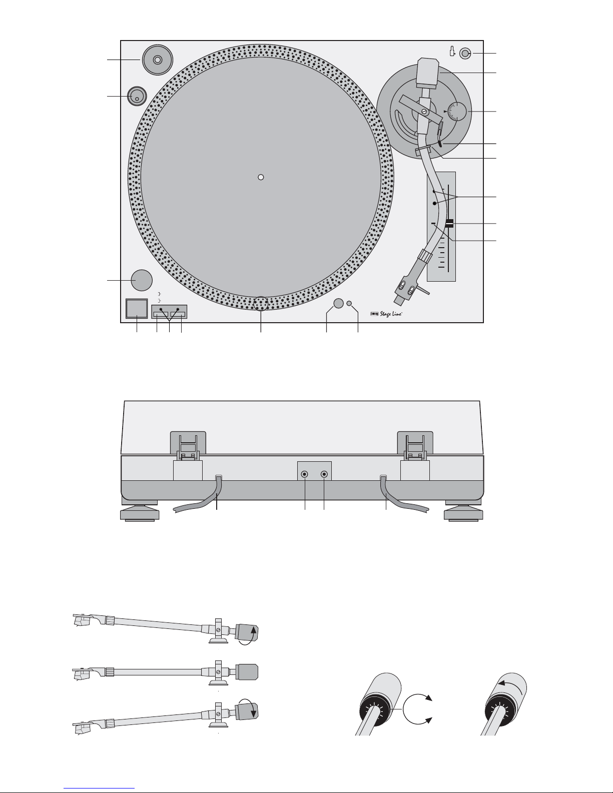
Tone arm balance ➂ Scale ring ➃ Stylus pressure ➄
adjustment
➁
1
2
3
16
17
18
13
12
11

Bitte klappen Sie die Seite 3 heraus. Sie sehen
dann immer die beschriebenen Bedienelemente
und Anschlüsse.
1 Übersicht der Bedienelemente und
Anschlüsse
1.1 Bedienelemente
1 Adapter für Single-Platten
2 Ein-/Ausschalter
3 Stroboskop-Lampe
4 Taste START/STOP
5 Taste für die Geschwindigkeit 33U/Min.
6 Geschwindigkeitsanzeige
7 Taste für die Geschwindigkeit 45U/Min.
8 Stroboskop-Ring
9 Beleuchtung für den Plattenteller
10 Ein-/Ausschalter für die Plattentellerbeleuchtung
11 Halterung für Ersatz-Systemträger
12 Gegengewicht für den Tonarm
13 Antiskating-Einstellung
14 Tonarm-Lift
15 Verriegelungshebel für den Tonarm
16 Geschwindigkeitsfeineinstellung; nur für den
Service in einer Fachwerkstatt bestimmt
17 Geschwindigkeitsregler
18 Anzeige-LED der Quarzsteuerung; leuchtet bei
Standardgeschwindigkeit [Geschwindigkeitsregler (17) in der Mittelposition eingerastet]
1.2 Anschlüsse
19 Cinch-Kabel für den Tonausgang zum Anschluss
an einen Verstärker oder an ein Mischpult
20 Anschluss zum Fernsteuern von Vor-/Rücklauf
21 Anschluss zum Fernsteuern von Start/Stopp
22 Netzkabel zum Anschluss an 230 V~/50Hz
2 Hinweise für den sicheren Gebrauch
Dieses Gerät entspricht der Richtlinie für elektromagnetische Verträglichkeit 89/ 336/ EWG und der
Niederspannungsrichtlinie 73/23/EWG.
Beachten Sie auch unbedingt die folgenden Punkte:
●
Verwenden Sie das Gerät nur im Innenbereich.
Schützen Sie es vor Tropf- und Spritzwasser,
hoher Luftfeuchtigkeit und Hitze (zulässiger Einsatztemperaturbereich 0–40 °C).
●
Stellen Sie keine mit Flüssigkeit gefüllten Gefäße,
z.B. Trinkgläser, auf das Gerät.
●
Nehmen Sie das Gerät nicht in Betrieb bzw. ziehen Sie sofort den Netzstecker, wenn:
1. sichtbare Schäden am Gerät oder an der Netzanschlussleitung vorhanden sind,
2. nach einem Sturz oder ähnlichem der Verdacht
auf einen Defekt besteht,
3. Funktionsstörungen auftreten.
Lassen Sie das Gerät in jedem Fall in einer Fachwerkstatt reparieren.
●
Eine beschädigte Netzanschlussleitung darf nur
durch den Hersteller oder eine autorisierte Fachwerkstatt ersetzt werden.
●
Ziehen Sie den Netzstecker nie an der Zuleitung
aus der Steckdose, immer am Stecker anfassen.
●
Verwenden Sie für die Reinigung nur ein trockenes, weiches Tuch, auf keinen Fall Chemikalien
oder Wasser.
●
Wird das Gerät zweckentfremdet, falsch bedient
oder nicht fachgerecht repariert, kann für eventuelle Schäden keine Haftung übernommen werden.
●
Soll das Gerät endgültig aus dem Betrieb genommen werden, übergeben Sie es zur umweltgerechten Entsorgung einem örtlichen Recyclingbetrieb.
3 Montage und Grundeinstellungen
Der Plattenteller, das Gegengewicht für den Tonarm
und die Abdeckhaube sind einzeln verpackt, damit
beim Transport der Plattenspieler nicht beschädigt
wird. Nach dem Auspacken lassen sich alle Teile
ganz einfach montieren. Die Verpackung sollte für
eventuelle Transporte aufgehoben werden.
3.1 Plattenteller montieren
1) Den Plattenteller auf die Achse des Plattenspielers stecken.
2) Von Hand den Plattenteller so weit drehen, bis
sich eines der Löcher in der Nähe der Stroboskop-Lampe (3) befindet und die Antriebsachse
des Motors zu sehen ist.
3) Der Gummi-Antriebriemen ist durch die Plattentellerlöcher zu sehen. Den Antriebsriemen fassen
und über die Antriebsachse legen.
4) Die beiliegende Filzmatte auf den Plattenteller
legen.
3.2 Gegengewicht für den Tonarm montieren
1) Das Gegengewicht (12) aus einem der beiden
seitlichen Styropor-Verpackungsteilen herausnehmen.
2) Mit einer Hand den T onarm in der Mitte festhalten.
Mit der anderen Hand das Gegengewicht auf das
Ende des Tonarmes stecken, bis es einrastet.
3) Mit dem Gegengewicht wird anschließend das
Gewicht genau eingestellt, mit dem die Abtastnadel auf der Schallplatte aufliegt.
Achtung! Das Gerät wird mit lebensgefährlicher
Netzspannung (230 V~) versorgt. Nehmen Sie deshalb nie selbst Eingriffe im
Gerät vor. Durch unsachgemäßes Vorgehen besteht die Gefahr eines elektrischen Schlages. Außerdem erlischt
beim Öffnen des Gerätes jeglicher
Garantieanspruch.
Please unfold page 3. Then you can always see
the operating elements and connections described.
1 Operating Elements and Connections
1.1 Operating Elements
1 Adapter for single records
2 Power switch
3 Stroboscope lamp
4 START/STOP button
5 Button for the 33rpm speed
6 Speed indication
7 Button for the 45rpm speed
8 Stroboscope ring
9 Target light
10 On/off switch for the target light
11 Support for replacement headshell
12 Counterweight for the tone arm
13 Antiskating adjustment
14 Lever for tone arm lift
15 Tone arm locking lever
16 Fine adjustment of pitch control; only destined
for servicing carried out by authorized personnel
17 Pitch control
18 LED for crystal control; only lights up at standard
speed [pitch control (17) locked into place in midposition]
1.2 Connections
19 Cable with phono connectors for signal output for
connection to an amplifier or a mixer
20 Connection for remote-controlling forward/back-
ward run
21 Connection for remote-controlling Start/Stop
22 Mains cable for connection to 230V~/50Hz
2 Safety Notes
The unit corresponds to the directive for electromagnetic compatibility 89/336 /EEC and to the low voltage directive 73/23/EEC.
It is essential to observe the following items:
●
The unit is suitable for indoor use only. Protect it
against dripping water and splash water, high
humidity, and heat (ambient temperature range
0–40°C).
●
Do not place any vessels filled with liquid,
e.g. drinking glasses, on the unit.
●
Do not operate the unit or immediately disconnect
the plug from the mains socket
1. if there is visible damage to the unit or to the
mains cable,
2. if a defect might have occurred after the unit
was dropped or suffered a similar accident,
3. if malfunctions occur.
In any case the unit must be repaired by skilled
personnel.
●
A damaged mains cable must be replaced by the
manufacturer or by skilled personnel only.
●
Never pull the mains cable to disconnect the
mains plug from the socket.
●
For cleaning only use a dry, soft cloth, by no
means chemicals or water.
●
If the unit is used for other purposes than originally
intended, if it is not correctly operated or not
repaired by skilled personnel, no liability for any
damage will be accepted.
●
If the unit is to be put out of operation definitively,
take it to a local recycling plant for disposal.
●
Important for U.K. Customers!
The wires in this mains lead are coloured in accordance with the following code:
blue = neutral
brown = live
As the colours of the wires in the mains lead of this
appliance may not correspond with the coloured
markings identifying the terminals in your plug,
proceed as follows:
1. The wire which is coloured blue must be connected to the terminal in the plug which is
marked with the letter N or coloured black.
2. The wire which is coloured brown must be connected to the terminal which is marked with the
letter L or coloured red.
3 Assembly and Basic Adjustments
The turntable platter, the counterweight for the tone
arm, and the dust cover are separately packed to
prevent damage to the turntable during transportation. After unpacking, the parts can be easily assembled. The packing material should be kept for transportation purposes.
3.1 Mounting the turntable platter
1) Place the turntable platter on the axle of the turntable.
2) Turn the platter by hand until one of the cutouts is
near the stroboscope lamp (3) and the driving
axle of the motor is visible.
3) The rubber driving belt is visible through the
cutouts of the turntable platter. Seize the driving
belt and place it over the driving axle.
4) Place the supplied felt pad on the turntable platter.
3.2
Mounting the counterweight for the tone arm
1) T ake the counterweight (12) out of one of the two
lateral polystyrene wrappings.
2) With one hand, hold the tone arm in its middle.
With the other hand, insert the counterweight on
the end of the tone arm until it locks into place.
3) The counterweight is then used for precise
adjustment of the stylus pressure on the record.
Attention!
The unit is supplied with hazardous mains
voltage (230V~). Leave servicing to
skilled personnel only. Inexpert handling
may cause an electric shock hazard.
Furthermore, any guarantee claim will
expire if the unit has been opened.
4
GB
D
A
CH

3.3 Auflagegewicht einstellen
1) Zuerst den Antiskating-Drehknopf (13) entgegen
dem Uhrzeigersinn auf „0“ drehen.
2) Die Schutzkappe für die Abtastnadel nach unten
abziehen.
3) Den Hebel für den T onarm-Lift (14) in die vordere
Position stellen.
4) Den Verriegelungshebel für den Tonarm (15)
nach rechts öffnen. Den Tonarm am Griff anfassen und ihn vorsichtig bis kurz vor den Plattenteller führen, so dass er sich frei nach oben und
unten bewegen lässt.
Achtung! Die Abtastnadel nirgends anstoßen
lassen.
5) Das Gegengewicht (12) so verdrehen, dass der
Tonarm genau waagerecht stehen bleibt und
nicht nach oben oder unten schwingt (Abb. 3).
Schwingt der Tonarm nach oben: Gegengewicht
entgegen dem Uhrzeigersinn drehen.
Schwingt der Tonarm nach unten: Gegengewicht
im dem Uhrzeigersinn drehen.
6) Den Tonarm zurück auf die Tonarm-Halterung
legen und mit dem Verriegelungshebel (15)
sichern.
7) Am Gegengewicht (12) befindet sich ein drehbarer, schwarzer Ring mit einer Skala. Die weiße
Linie auf dem Tonarm zeigt auf irgendeinen Wert
der Skala. Ohne dass das Gegengewicht verdreht wird, nur den Ring auf „0“ drehen (Abb. 4).
8) Auf der Skala wird das Auflagegewicht in Gramm
abgelesen. Für das mitgelieferte Abtastsystem ist
ein Auflagegewicht von 2,5 g erforderlich. Dazu
das Gegengewicht (nicht den Ring mit der Skala
allein!) entgegen dem Uhrzeigersinn bis zur „2,5“
drehen (Abb. 5). Für andere Abtastsysteme das
Auflagegewicht einstellen, welches in den dazugehörigen technischen Daten angeben ist.
3.4 Antiskating einstellen
Beim Abspielen einer Schallplatte treten Kräfte an
der Abtastnadel auf, welche durch die AntiskatingEinrichtung aufgehoben werden. Dazu den Antiskating-Drehknopf (13) von „0“ auf den Wert einstellen,
der dem Auflagegewicht gleich ist, d.h. bei dem mitgelieferten Abtastsystem auf „2,5“. Der Wert ist
neben dem Pfeil auf dem Drehknopf abzulesen.
3.5 Abdeckhaube montieren
Die zwei Scharniere für die Abdeckhaube aus den
beiden Styropor-Verpackungsteilen herausnehmen
und auf die Abdeckhaube stecken. Die Abdeckhaube mit den Scharnieren auf den Plattenspieler
aufsetzen. Die Abdeckhaube kann jederzeit wieder
abgenommen werden, wenn sie beim Betrieb stört
(z.B. beim Disco-Betrieb).
4 Plattenspieler anschließen
Das Cinch-Anschlusskabel (19) in die Anschlussbuchsen für einen Plattenspieler mit Magnetsystem
am Verstärker oder Mischpult stecken. Dabei auf die
farbige Kennzeichnung der Buchsen und Stecker achten (rot = rechter Kanal, weiß = linker Kanal). Den
Masse-Anschluss des Kabels an die Masse-Klemme
des Verstärkers oder Mischpultes klemmen. Den Netzstecker in eine Steckdose (230V~/ 50 Hz) stecken.
5 Bedienung
5.1 Schallplatte abspielen
1) Die Schutzkappe für die Abtastnadel nach unten
abziehen.
2) Zum Einschalten den Schalter POWER (2)
betätigen. Die Geschwindigkeitsanzeige (6) und
die Stroboskop-Lampe (3) leuchten. Bei Bedarf
die Plattentellerbeleuchtung (9) mit dem Druckschalter (10) einschalten.
3) Die Geschwindigkeit wählen:
33U/Min. für Langspielplatten mit der Taste (5),
45U/Min. für Single-Platten mit der Taste (7).
Die eingestellte Geschwindigkeit wird durch die
Anzeige (6) angegeben.
4) Die Schallplatte auflegen. Bei Single-Platten den
Adapter (1) mit auflegen.
5) Den Hebel für den Tonarm-Lift (14) in die hintere
Position stellen. Den Verriegelungshebel (15) für
den Tonarm nach rechts öffnen. Den Tonarm am
Griff anfassen, und die Abtastnadel über den
Anfang der Schallplatte stellen.
6) Den Hebel für den T onarm-Lift (14) in die vordere
Position stellen. Der Tonarm senkt sich langsam
auf die Schallplatte.
7) Mit der Taste START/STOP (4) die Platte starten.
Während des Abspielens kann die Platte für eine
Unterbrechung mit der Taste START/STOP an
jeder Stelle gestoppt und wieder gestartet werden.
8) Am Ende der Schallplatte den Tonarm mit dem
Tonarm-Lift (14) anheben und ihn per Hand auf
den Tonarm-Halter zurückführen. Den Plattenteller mit der Taste START/STOP (4) stoppen.
9) Nach dem Gebrauch des Plattenspielers den T onarm mit dem Verriegelungshebel (15) sichern,
und das Gerät mit dem Schalter POWER (2) ausschalten. Die Abdeckhaube zum Schutz gegen
Staub herunterklappen.
5.2 Einstellung der Geschwindigkeit
Bei Bedarf kann die Geschwindigkeit des Plattenspielers mit dem Schieberegler (17) um 10 % erhöht
oder verringert werden. In der Mittelstellung [Regler
rastet ein, Anzeige-LED (18) leuchtet] stimmt die
Geschwindigkeit genau und kann auf dem Stroboskop-Ring (8) des Plattentellers kontrolliert werden.
Bei sich drehendem Plattenteller den Teil des
Stroboskop-Rings (8) betrachten, der von der Stroboskop-Lampe (3) beleuchtet wird. (Eventuell die
Raumbeleuchtung verringern.) Bei exakt eingestellter Geschwindigkeit bleiben die Markierungen auf
dem Stroboskop-Ring scheinbar stehen:
bei 33 U/Min. auf dem oberen Ring,
bei 45 U/Min. auf dem zweiten Ring.
3.3 Adjusting the stylus pressure
1) First turn the antiskating knob (13) counter-clockwise to “0”.
2) Pull down the protective cap of the stylus.
3) Place the lever for the tone arm lift (14) in the
front position.
4) Open the tone arm locking lever (15) to the right.
Seize the handle of the tone arm and lead it
carefully just before the turntable platter so that it
can be moved upwards and downwards.
Attention! The stylus must not hit against anything.
5) Turn the counterweight (12) until the tone arm
remains in a horizontal position and does not
move upwards or downwards (fig. 3).
If the tone arm moves upwards: Turn the counterweight counter-clockwise.
If the tone arm moves downwards: Turn the
counterweight clockwise.
6) Put the tone arm back onto the tone arm support
and secure it with the locking lever (15).
7) The counterweight (12) is provided with a black
rotary ring with a scale. The white line on the tone
arm points to a value on this scale. Without turning the counterweight, only turn the ring to “0”
(fig. 4).
8) The scale indicates the stylus pressure in grams.
A stylus pressure of 2.5g is required for the supplied stylus system. For this purpose, turn the
counterweight (not only the ring with the scale!)
counter-clockwise to “2.5” (fig. 5). For other stylus systems, adjust the stylus pressure indicated
in the corresponding specifications.
3.4 Adjusting the antiskating facility
When playing a record, forces occur on the stylus
which are compensated by the antiskating facility.
For this purpose, adjust the antiskating knob (13)
from “0” to the value which equals the stylus pressure, i.e. for the supplied stylus system to “2.5”. The
arrow next to the knob points to the corresponding
value on the knob.
3.5 Mounting the dust cover
Take the two hinges for the dust cover out of the two
polystyrene wrappings and attach them to the dust
cover. Place the dust cover with the hinges on the
turntable. The dust cover can be removed any time
if it interferes with the operation (e. g. during disco
operation).
4 Connecting the turntable
Connect the cable with phono connectors (19) to the
jacks for a turntable with magnetic system on an
amplifier or a mixer. Observe the coloured marking
of the jacks and the connectors (red = right channel,
white = left channel). Connect the ground connection of the cable to the ground terminal of the amplifier or the mixer. Connect the mains plug to a mains
socket (230V~/50 Hz).
5 Operation
5.1 Playing a record
1) Pull down the protective cap of the stylus.
2) For switching on, actuate the POWER switch (2).
The speed indication (6) and the stroboscope
lamp (3) light up. Switch on the target light (9)
with the push-button switch (10), if required.
3) Select the speed:
33rpm for long-playing records with the button (5),
45rpm for single records with the button (7).
The speed indication (6) shows the selected
speed.
4) Put on the record. For single records, use the
adapter (1).
5) Place the lever for the tone arm lift (14) in the
back position. Open the locking lever (15) for the
tone arm to the right. Seize the handle of the tone
arm and place the stylus above the beginning of
the record.
6) Place the lever for the tone arm lift (14) in the
front position. The tone arm is slowly lowered
onto the record.
7) Start the record with the START/STOP button
(4). The playing can be interrupted and restarted
at any spot with the START/STOP button.
8) At the end of the record, lift the tone arm with the
tone arm lift (14) and put it back onto the tone
arm support by hand. Stop the turntable platter
with the START/STOP button (4).
9) After use of the turntable, secure the tone arm
with the locking lever (15) and switch off the unit
with the POWER switch (2). Close the cover for
protection against dust.
5.2 Adjusting the speed
The speed of the turntable can be increased or
decreased with the sliding control (17) by 10 %, if
required. In mid-position [control locks into place,
LED (18) lights up], the speed is precisely adjusted
and can be checked on the stroboscope ring (8) of
the turntable platter.
While the turntable platter is revolving, observe
the part of the stroboscope ring (8) which is illuminated by the stroboscope lamp (3). (Reduce the
room lighting, if required.) If the speed is precisely
adjusted, the markings on the stroboscope ring
seem to stand still:
at 33 rpm on the upper ring
at 45 rpm on the second ring
5.3 Remote control of Start/Stop
For disco operation, the Start/Stop function can be
remote-controlled via a separate switch, e. g. via a
mixer with a so-called fader start. If the control for
the turntable is advanced on the mixer, the turntable
will automatically start, or it will stop again if the control is closed.
5
D
A
CH
GB
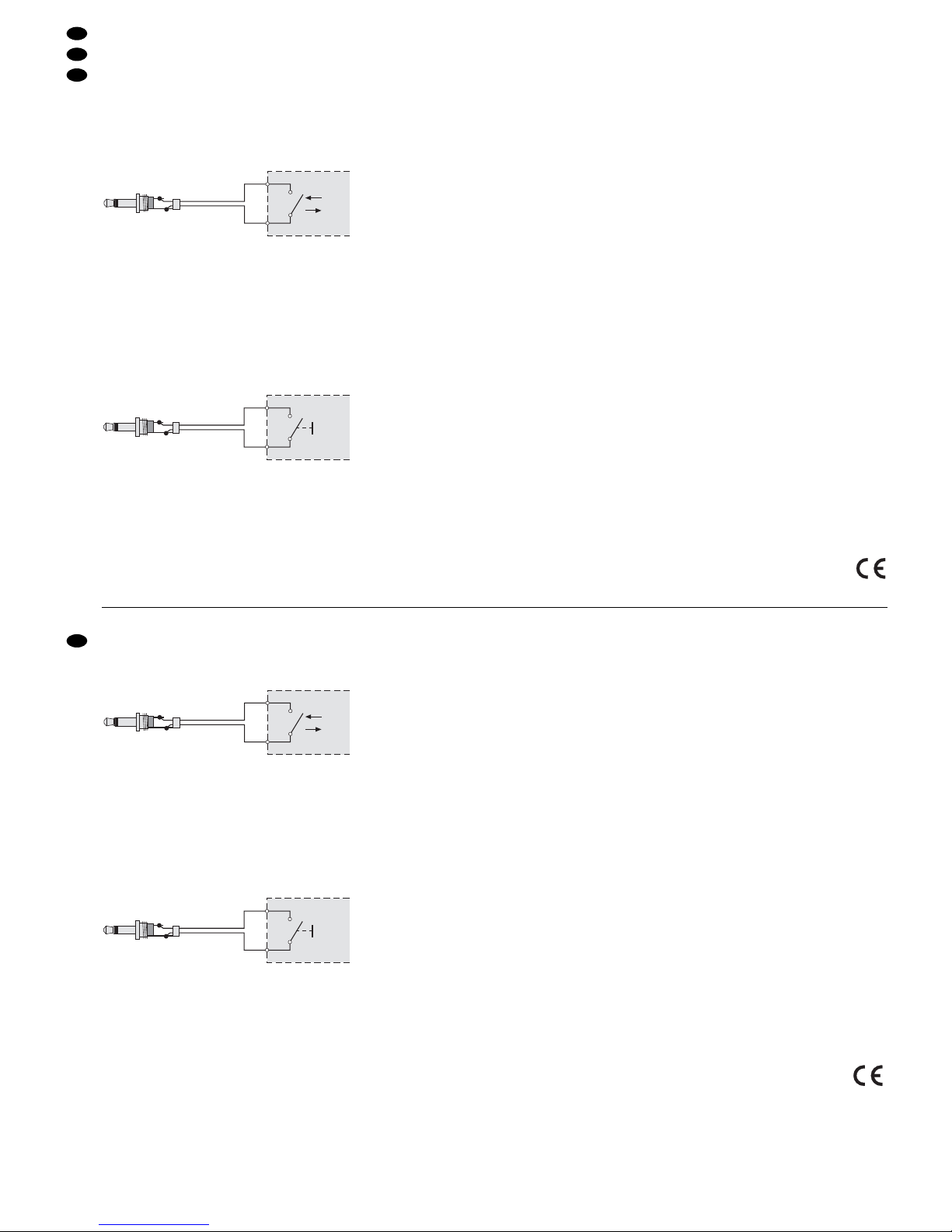
5.3 Fernsteuern von Start/Stopp
Für den Disco-Betrieb kann die Funktion Start/
Stopp über einen separaten Schalter ferngesteuert
werden, z. B. über ein Mischpult mit sogenannten
Faderstart. Wenn am Mischpult der Regler für den
Plattenspieler geöffnet wird, startet automatisch der
Plattenspieler bzw. stoppt wieder, wenn der Regler
geschlossen wird.
Den Schalter bzw. das Mischpult über einen
2-poligen Klinkenstecker (3,5 mm) an die Buchse
REMOTE START/STOP (21) anschließen.
Verbindungskabel für den Faderstart
mit 3,5-mm-Mono-Klinkenstecker
5.4 Fernsteuern von Vor-/Rücklauf
Für besondere Effekte oder zum Auffinden einer
bestimmten Stelle auf der Schallplatte lässt sich die
Drehrichtung über einen separaten Taster zwischen
Vor-undRücklauf umschalten. Den Taster über
einen 2-poligen Klinkenstecker (3,5mm) an die
Buchse REMOTE FORW/BACKW (20) anschließen.
Verbindungskabel
mit 3,5-mm-Mono-Klinkenstecker
6 Zubehör
6.1 Ersatz-Abtastsystem und -Nadel
Bei Bedarf kann das Abtastsystem oder die Abtastnadel leicht ausgewechselt werden. Im Fachhandel
sind entsprechende Ersatzteile erhältlich, z.B.:
Diamant-Abtastnadel EN-24SP von MONACOR,
Abtast-Magnetsystem EN-24 von MONACOR.
Nach dem Austausch des Abtastsystems das Auflagegewicht und Antiskating neu einstellen (siehe
Kapitel 3.3 und 3.4).
6.2 Ersatz-Systemträger
Ein Ersatz-Systemträger komplett mit einem Abtastsystem (z. B. EN-120 von MONACOR; im Fachhandel erhältlich) kann in die Halterung (11) gesteckt
werden. Damit ist bei Bedarf immer sofort Ersatz
verfügbar. Der Systemträger lässt sich schnell durch
Ab- und Anschrauben austauschen. Anschließend
das Auflagegewicht und Antiskating neu einstellen
(siehe Kapitel 3.3 und 3.4).
7Wartung
7.1 Pflege
Das Plattenspielergehäuse und die Abdeckhaube
am besten nur mit einem Staubtuch oder angefeuchteten Lappen (nicht tropfnass!) abwischen.
Keinen Alkohol, Chemikalien oder scharfe Reinigungsmittel verwenden! Zum Entstauben der
Abtastnadel und Schallplatten ist im Fachhandel
entsprechendes Zubehör erhältlich, z.B.:
Carbonfaser-Plattenbürste DC-100 von MONACOR
7.2 Transport
Wollen Sie den Plattenspieler versenden, so achten
Sie darauf, dass der Plattenteller und alle anderen
Baugruppen des Gerätes nur original verpackt
und/ oder extra transportgesichert verschickt werden. Gehäuse- und Geräteschäden, die durch einen
unsachgemäß lose verpackten Plattenteller (z.B.
Plattenteller nicht von der Achse genommen und
nicht gesichert o.ä.) verursacht werden, unterliegen
nicht der Garantie und sind deshalb kostenpflichtig!
Für den Versand unbedingt beachten:
1) Die Schutzkappe für die Abtastnadel aufstecken.
2) Den Tonarm mit dem Verriegelungshebel (15)
sichern.
3) Das Gegengewicht für den Tonarm (12) durch
Drehen im Uhrzeigersinn abschrauben.
4) Der Plattenteller von der Achse abnehmen, einzeln verpacken und gegen Verrutschen sichern.
5) Am besten den Original-Verpackungskarton verwenden.
8Technische Daten
Plattenteller:. . . . . . . . . . . Ø 332mm
Geschwindigkeiten: . . . . . 33
1
/3 U/Min., 45 U/Min.
Geschwindigkeits-
Feinregelung:. . . . . . . . . . ±10 %
Start-Drehmoment: . . . . . 0,3kg/cm
Hochlaufzeit: . . . . . . . . . . < 0,7 Sekunden
Gleichlaufschwankungen: < 0,25 %
Stromversorgung: . . . . . . 230V~/50Hz/10VA
Zulässige
Einsatztemperatur: . . . . . 0 –40°C
Abmessungen (B x H x T): 450 x 152 x 352 mm
Gewicht:. . . . . . . . . . . . . . 4,2kg
Laut Angaben des Herstellers.
Änderungen vorbehalten.
➆
Forw.
Backw.
Start
Stop
Connect the switch or the mixer to the jack
REMOTE START/STOP (21) via a 2-pole plug
(3.5mm).
Connection cable for the fader start
with 3.5 mm mono plug
5.4 Remote control of forward/backward run
For special effects or for finding a certain spot on the
record, the revolving direction can be switched from
forward to backward and vice versa via a separate
push-button. Connect the push-button to the jack
REMOTE FORW/BACKW (20) via a 2-pole plug
(3.5mm).
Connection cable with 3.5 mono plug
6 Accessories
6.1 Replacement phono cartridge system
and stylus
The phono cartridge system or the stylus can easily
be replaced, if required. The corresponding replacement parts are available at your retailer, e.g.:
diamond stylus MONACOR EN-24SP,
stereo magnetic phono cartridge system MONACOR
EN-24.
After replacing the phono cartridge system, readjust
the stylus pressure and the antiskating facility (see
chapters 3.3 and 3.4).
6.2 Replacement headshell
Areplacement headshell complete with a phono cartridge system (available at your retailer, e.g.
MONACOR EN-120) can be put on the support
(11). Thus, a replacement is immediately available, if
required. The headshell can be easily replaced by
unscrewing the existing one and screwing the new
one on. After replacement, readjust the stylus pressure and the antiskating facility (see chapters 3.3
and 3.4).
7 Maintenance
7.1 Cleaning
It is recommended to clean the turntable housing
and the dust cover only with a dust cloth or a damp
cloth (not dripping wet!). Do not use alcohol, chemicals, or strong detergents! For dusting the stylus and
the records, the corresponding accessories are
available at your retailer, e.g.:
carbon fibre brush for records DC-100 by MONACOR
7.2 Transportation
If the turntable is to be dispatched, pay attention that
the turntable platter and all other components of the
unit are packed in their original packing material
and/or are especially secured for transportation.
Any damage to the housing or to the unit due to a
turntable platter that was not correctly secured (e.g.
turntable platter was not removed from the axle and
not secured, etc.) is not covered by the guarantee
and therefore the repair will be charged!
It is essential to observe the following instructions for dispatch:
1) Place the protective cap on the stylus.
2) Secure the tone arm with the locking lever (15).
3) Unscrew the counterweight for the tone arm (12)
by turning it clockwise.
4) Remove the turntable platter from the axle, pack
it separately, and secure it against displacement.
5) It is recommended to use the original packing
material.
8 Specifications
Turntable platter: . . . . . . . Ø 332 mm
Speeds: . . . . . . . . . . . . . . 33
1
/3 rpm, 45 rpm
Fine adjustment of
pitch control: . . . . . . . . . . ±10%
Starting torque: . . . . . . . . 0.3kg/cm
Starting time: . . . . . . . . . . < 0.7seconds
Wow and flutter:. . . . . . . . < 0.25%
Power supply: . . . . . . . . . 230V~/50Hz/10VA
Admissible range
of application: . . . . . . . . . 0 –40°C
Dimensions (W x H x D): . 450 x 152 x 352mm
Weight:. . . . . . . . . . . . . . . 4.2kg
According to the manufacturer.
Subject to change.
➆
Forw.
Backw.
➅
Start
Stop
6
GB
D
A
CH
 Loading...