


M550
RADIO REMOTE CONTROL
M550
User’s Manual
No part of this manual may be reproduced in any way without written authorization from IMET. This manual is subject to change
with no further notice. Every possible care has been taken in compiling and verifying the contents of this manual; however, IMET
declines any responsibility deriving from using the manual or from any errors or omissions in the information contained herein.
Furthermore, IMET cannot be held responsible for damages or problems deriving from using non-original accessories or spare
parts. The same applies to any person or company involved in the realization of this manual
M550 ALL1-EN.doc 3nd edition- 04 July 2012
IMET S.r.l. via Fornace no. 8, 33077 Sacile (PN) Italy
Tel +39.0434.7878 Fax +39.0434. 737848
.
IMET - M550 ALL1-EN 1/53

CONTENTS
CONTENTS ............................................................................................................................................................ 2
INTRODUCTION .................................................................................................................................................. 4
1. IDENTIFICATION DATA ......................................................................................................................... 5
1.1. DOCUMENTATION........................................................................................................................................... 6
2. CONVENTIONS USED IN THIS MANUAL ............................................................................................ 7
3. CAUTION .................................................................................................................................................... 7
3.1. RISK ANALYSIS ................................................................................................................................................ 7
3.2. APPLICATIONS ................................................................................................................................................ 7
4. PREVENTIVE MAINTENANCE .............................................................................................................. 8
4.1. ROUTINE MAINTENANCE TO BE CARRIED OUT BY OPERATOR .............................................................................. 8
4.2. MAINTENANCE AND INTERNAL CHECKS ............................................................................................................ 8
5. INSTALLING THE RADIO REMOTE CONTROL ................................................................................. 9
5.1. RECEIVING UNIT DIMENSIONS AND DRILLING DIAGRAM .................................................................................... 9
5.2. CONNECTING THE RECEIVER ......................................................................................................................... 11
5.2.1. INSTALLING THE EXTERNAL ANTENNA ............................................................................................................ 11
5.2.2. STOP (E-STOP) ......................................................................................................................................... 12
5.2.3. SAFETY STOP (S-STOP) .............................................................................................................................. 12
5.3. BASIC FUNCTIONS......................................................................................................................................... 13
5.4. CONNECTION DIAGRAMS OF H RECEIVERS ..................................................................................................... 13
5.4.1. H RECEIVER WITH ANALOG OUTPUT CARD AND DATA FEEDBACK CARD ............................................................ 14
5.4.2. POWER SUPPLY CONNECTIONS OF H-DC AND H-AC RECEIVERS .................................................................... 15
5.4.3. ANALOG COMMAND CARD ............................................................................................................................. 16
5.4.4. LOGIC BOARD ............................................................................................................................................... 17
5.4.5. DATA FEEDBACK CARD ................................................................................................................................. 17
5.4.6. RELAY CONTROL CARDS ................................................................................................................................ 18
5.4.7. POTENTIOMETER CARD ................................................................................................................................. 18
5.5. CONNECTION DIAGRAMS FOR L AND K RECEIVERS ......................................................................................... 19
5.5.1. L-AC VERSION ............................................................................................................................................ 19
5.5.2. L-DC VERSION ............................................................................................................................................. 20
5.5.3. K VERSION ................................................................................................................................................... 21
5.5.4. RELAY CONTROL CARDS FOR L AND K RECEIVERS ........................................................................................... 22
5.5.5. OTHER CONTROL CARDS FOR L-DC AND K-DC RECEIVERS ............................................................................ 23
5.6. SERIAL DATA TRANSMISSION .......................................................................................................................... 24
5.6.1. USER SERIAL (RS232) ................................................................................................................................... 24
5.6.2. SERIAL CONNECTION CABLE .......................................................................................................................... 24
5.7. CONNECTION DIAGRAMS FOR M-AC RECEIVERS ............................................................................................ 25
5.7.1. M-AC RECEIVER .......................................................................................................................................... 25
5.7.2. COMMON CONNECTIONS ON M-AC TRANSCEIVERS ........................................................................................ 26
5.7.3. M-AC TRANSCEIVERS: DATA ACQUISITION CONNECTIONS ............................................................................... 27
6. USING THE RADIO REMOTE CONTROL ........................................................................................... 28
6.1. SAFETY RULES .............................................................................................................................................. 28
6.2. POWERING AND STARTING THE RADIO REMOTE CONTROL ............................................................................... 28
6.3. STOP .......................................................................................................................................................... 28
6.4. TURNING OFF THE REMOTE CONTROL ............................................................................................................ 28
6.5. AUTO POWER-OFF ........................................................................................................................................ 28
6.6. MEANING OF LEDS ...................................................................................................................................... 29
6.7. TRANSMITTING UNIT POWER SUPPLY .............................................................................................................. 30
6.7.1. BATTERY STATE OF CHARGE .......................................................................................................................... 30
6.7.2. CHANGING AND CHARGING THE BATTERY ...................................................................................................... 30
6.8. DIP-SWITCH PROGRAMMABLE OUTPUT CONFIGURATIONS ............................................................................... 31
7. RADIO REMOTE CONTROL OPTIONS ............................................................................................... 32
2/53 IMET - M550 ALL1-EN

7.1. MTRS AND MTRS EASY OPTION ................................................................................................................... 32
7.1.1. TRANSMITTER .............................................................................................................................................. 32
7.1.1.1. DEFINITION OF COMBINATION ................................................................................................................. 32
7.1.1.2. SELECTING THE DESIRED COMBINATION .................................................................................................. 32
7.1.1.3. LOCK PROCEDURE .................................................................................................................................. 32
7.1.1.4. RADIO REMOTE CONTROL START-UP ........................................................................................................ 33
7.1.1.5. UNLOCK PROCEDURE .......................................................................................................................... 33
7.1.1.6. FREQUENCY CHANGE .............................................................................................................................. 33
7.1.2. RECEIVER .................................................................................................................................................... 33
7.1.3. ANOMALIES .................................................................................................................................................. 34
7.2. DSC OPTION ............................................................................................................................................... 34
7.3. IREADY OPTION .......................................................................................................................................... 35
7.3.1. WARNINGS ................................................................................................................................................... 35
7.3.2. TRANSMITTER ............................................................................................................................................... 35
7.3.3. RECEIVER .................................................................................................................................................... 35
7.3.4. OPERATION ................................................................................................................................................. 36
7.3.5. TECHNICAL CHARACTERISTICS ...................................................................................................................... 37
8. CHANGING THE OPERATING FREQUENCY .................................................................................... 38
8.1. BEFORE CHANGING FREQUENCY ................................................................................................................... 38
8.2. CHANGING FREQUENCY ................................................................................................................................ 38
8.3. AVAILABLE FREQUENCIES ............................................................................................................................. 39
9. TROUBLESHOOTING ............................................................................................................................ 40
9.1. MALFUNCTIONS IN THE TRANSMITTER’S STOP CIRCUIT ................................................................................. 41
9.2. PASSIVE EMERGENCY .................................................................................................................................... 41
9.3. TECHNICAL ASSISTANCE ............................................................................................................................... 41
10. TECHNICAL SPECIFICATIONS ........................................................................................................... 42
10.1. WAVE TRANSMITTER .................................................................................................................................... 43
10.2. THOR AND ZEUS TRANSMITTERS ................................................................................................................. 43
10.3. S1, S2 AND G4 TRANSMITTERS ...................................................................................................................... 43
10.4. M8 TRANSMITTER ......................................................................................................................................... 43
10.5. H RECEIVERS ................................................................................................................................................ 44
10.6. L RECEIVER .................................................................................................................................................. 45
10.7. K RECEIVER.................................................................................................................................................. 46
10.8. M-AC RECEIVERS ......................................................................................................................................... 47
10.9. CB5000-AC, CB5000-DC BATTERY CHARGERS FOR WAVE TRANSMITTERS ................................................... 49
10.10. CB3600-AC, CB3600-DC BATTERY CHARGER FOR THOR AND ZEUS TRANSMITTERS ................................... 49
10.11. CB6000-AC, CB6000-DC BATTERY CHARGER FOR S1, S2 AND G4 TRANSMITTERS ........................................ 50
11. RADIO REMOTE CONTROL SPARE PARTS LIST ............................................................................. 51
12. DISPOSAL ................................................................................................................................................ 52
ANNEXES ............................................................................................................................................................ 52
ANNEX A
ANNEX B
ANNEX C
ANNEX D FOR K-DC RECEIVERS .............................................................................................................................. 52
OTHER ANNEXES ...................................................................................................................................................... 52
13. DECLARATION OF CONFORMITY 0470 .......................................................................................... 53
IMET - M550 ALL1-EN 3/53
INTRODUCTION
The M550 family is the result of IMET’s many years’ experience in the production of radio remote
controls. IMET radio remote controls are advanced instruments designed and built using state-of-theart technology.
IMET M550 radio remote controls are available in a large number of versions for any application. They
are easy to install and they become an integral part of any machine that can be operated by remote
control.
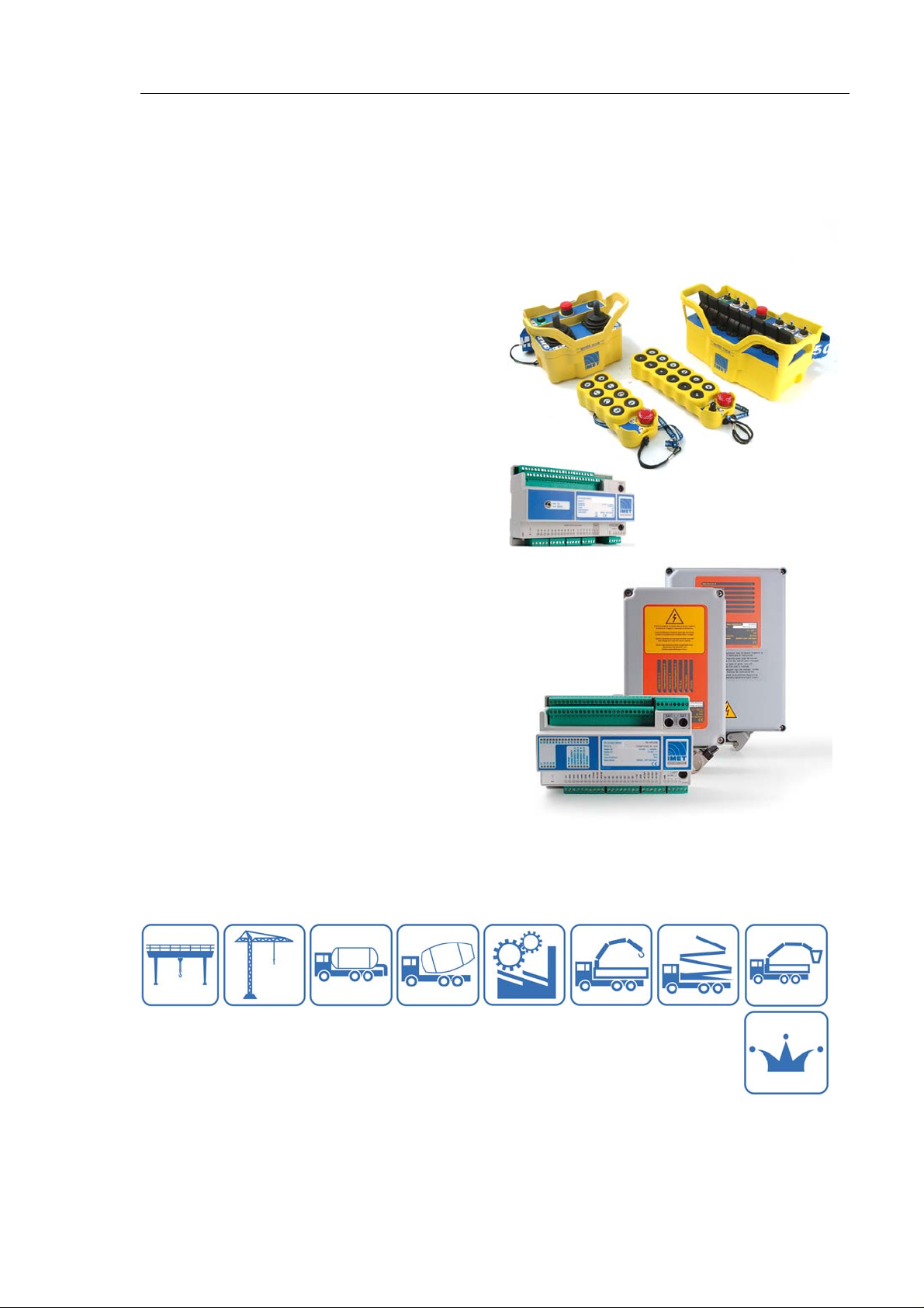
IMET radio remote controls come in many
versions: simple units with single transmission
and digital controls (ON/OFF), or more complex
units with digital/analog controls, CAN-bus and
dual transmission (data-feedback option).
The practical, ergonomic control panel lets you
manage all machine functions and perform the
most difficult operations from a safe position.
The units are easily identified by the ID code
printed on the nameplate affixed to every unit.
The meaning of the ID codes is shown in the
tables on pages 5 and 6.
The casings are made of shockproof plastic to
guarantee complete functionality even in the
toughest operation conditions.
M550 portable transmitters are equipped with a
removable, rechargeable sealed battery,
ensuring continuous operation over long work
shifts even in extreme environmental conditions.
The frequency synthesis radio section (PLL) lets
you change the frequency of the transmission
channel directly on the control panel.
Continuous, encoded radio transmission is used:
the receivers are designed to recognize control
signals coming from transmitters having the
same ID code. Signals coming from other
transmitters are ignored. . In the presence of
interference, bad reception or interruption of the
radio signal, the receiver automatically puts itself
in stop status, that involves opening the E-STOP
circuit (clause 9.2.7.3 EN 60204-32).
Every radio remote control is designed and built in conformity with the European Directives and with
the relevant standards and can be used to set up a wireless control station complying with the strictest
safety requirements.
4/53 IMET - M550 ALL1-EN
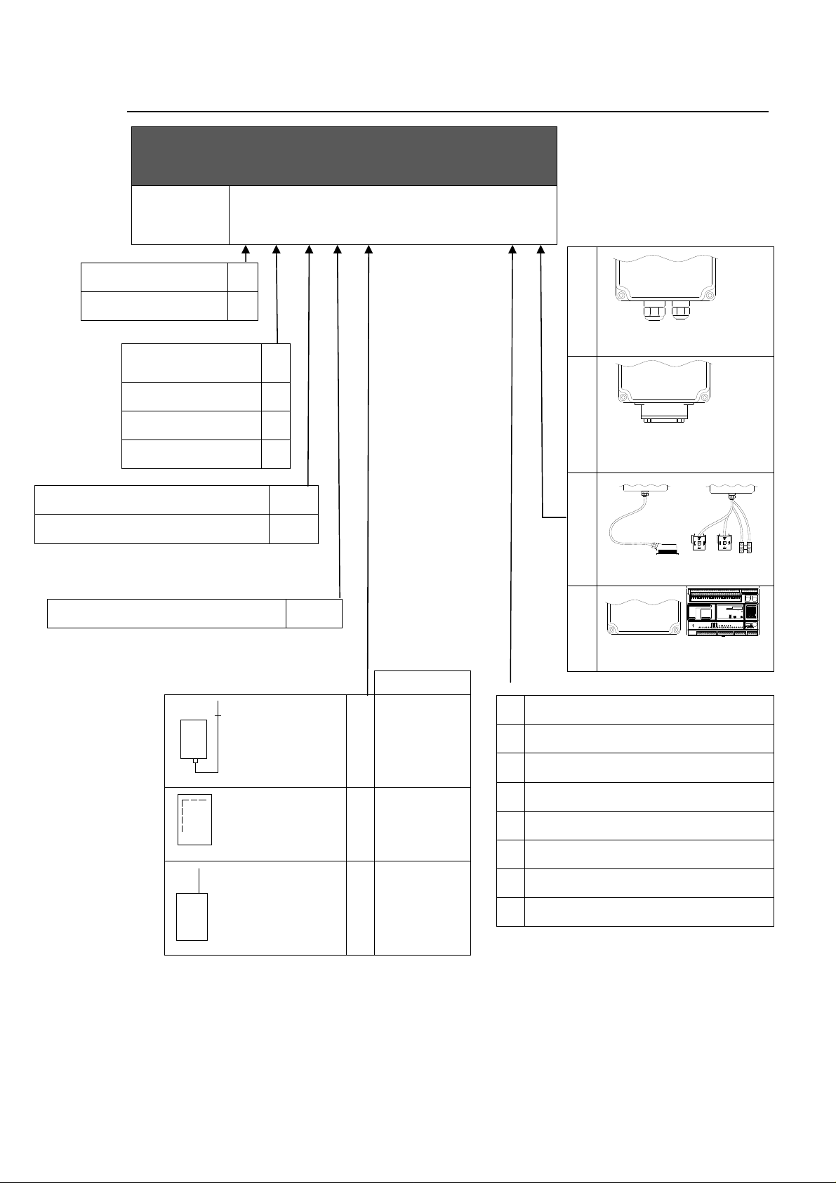
1. Identification data
M550
Single transmission
Dual transmission
Integrated circuit
board
Modular circuit board
DIN rail
BUS receiver
S
D
RECEIVING UNIT ID
L
H
M
K
H
Cable clamp output
I
Recessed multipolar plug
output
Alternating current power supply
Direct current power supply
Project reference number
External antenna
Internal antenna
AC
DC
nnnn
Version
L and K
O
H
M
L and K
I
H
L-AC only
S
L
Cable + plug output
Unwired output
M
24V AC power supply
A
48V AC power supply
B
55V AC power supply
C
110V AC power supply
D
230V AC power supply
E
Power supply selectable from A to E
F
18-28V AC power supply
G
B1B2B3B4B5B6B7B8A1A2A3A4A5A6A7
C1C2C3C4C5
LB534
ANT
T 5A L250VT 5A L250V
LB309
A8
TRX Unit Mod. M550D MAC
LB304
Serial no.
Supply AC 13 - 24V 50/60Hz
13 - 24VSupply DC
Power
1,2A 20VA
Radio Model M550D - UHF ISM Band
DATA ERROR CH. A
EMERGENCY CH. A
POWER SUPPLY
EMERGENCY CH. B
DATA ERROR CH. B
WORKING
RF BUSY
0470
LB305
LB306
T 1.25A L250V
13 - 24V
ACK
RTS
RXD
TXD
ERROR
STROBE
AD OUT 8
AD OUT 7
AD OUT 6
AD OUT 5
GND
OUT VREFD0D1D2D3D4D5D6D7
+VIN
GND
AIN1
AIN2
AIN3
AIN4
+5V
LN
747372717069686766656463626160595857565554535251
7576 7778 79
LB422
12-28V DC/AC power supply
N
Whip antenna
IMET - M550 ALL1-EN 5/53
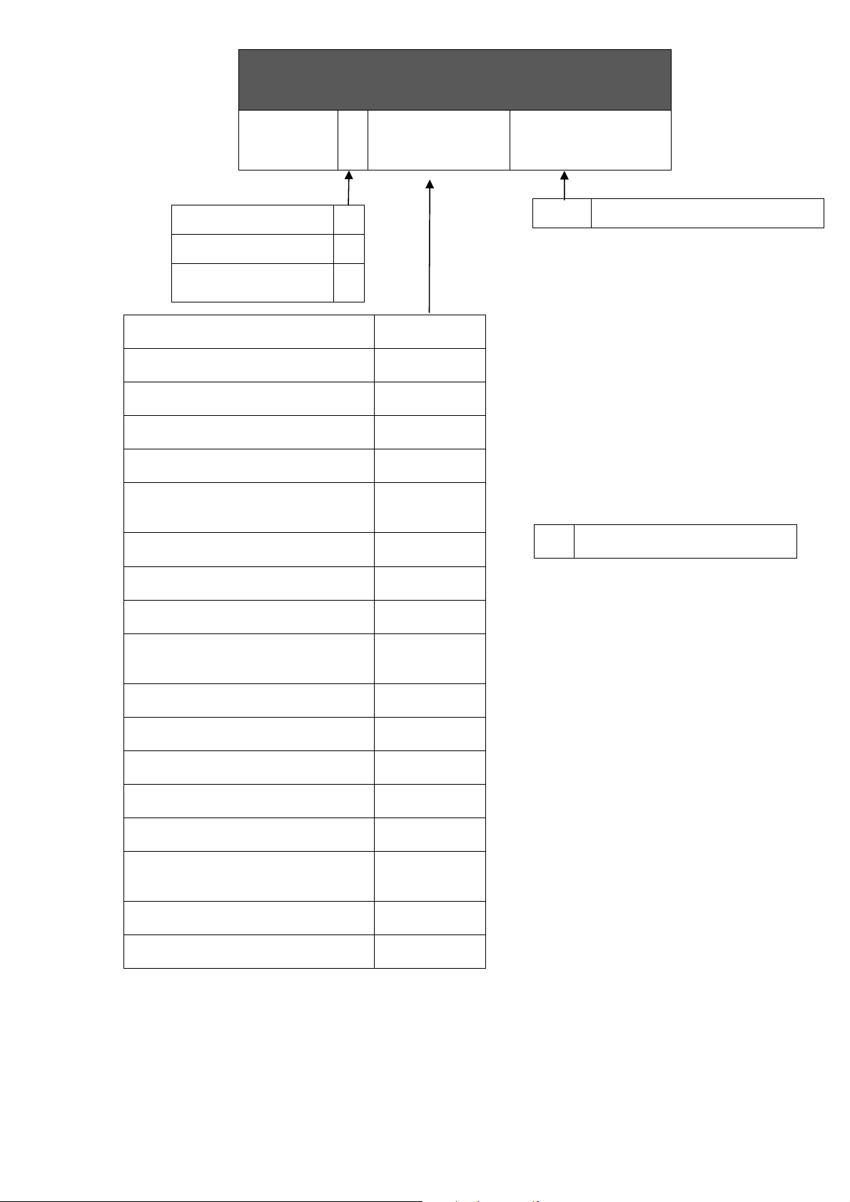
TRANSMITTING UNIT ID
M550
Pushbutton transmitter with 12
buttons + Start/Stop
Pushbutton transmitter with 10
buttons + Start/Stop
Pushbutton transmitter with 8
buttons + Start/Stop
Pushbutton transmitter with 6
buttons + Start/Stop
Pushbutton transmitter with 4
buttons + Start/Stop
Transmitter in THOR casing with
buttons, toggle switches and
potentiometers
Transmitter in THOR casing with
single axis joysticks
Transmitter in THOR casing with
single axis and dual axis joysticks
Transmitter on THOR casing with
dual axis joysticks
Transmitter in ZEUS casing with
buttons, toggle switches and
potentiometers
Transmitter in ZEUS casing with
single axis joysticks
Transmitter in ZEUS casing with
single axis and dual axis joysticks
Transmitter in ZEUS casing with
dual axis joysticks
Transmitter on DIN rail powered
from power panel
Transmitter on S casing with toggle
switches and buttons
Transmitter in S casing with
selectors, buttons and
potentiometers
Transmitter in G casing, compact
version
Transmitter in G casing, standard
version
Single transmission
Dual transmission
Transmission exclusively
by way of cable
S
D
F
WAVE L12
WAVE L10
WAVE S8
WAVE S6
WAVE S4
THOR NJ
THOR M#
THOR X#
THOR B#
ZEUS NJ
ZEUS M#
ZEUS X#
ZEUS B#
M8
S1
S2
G4S
G4L
nnnn
# =
Project reference number
1 to 8 joysticks, depending on
the type of joystick and casing
1.1. Documentation
All IMET radio remote controls are accompanied by the following documents:
• User’s Manual (the annexes are an integral part of the manual)
• Warranty Certificate
If any documents are missing, please contact IMET and provide the unit’s serial number.
6/53 IMET - M550 ALL1-EN
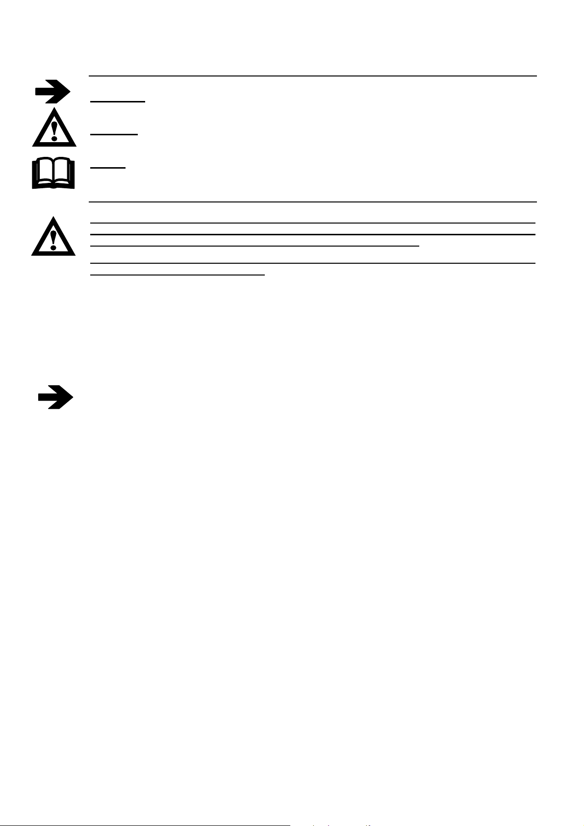
2. CONVENTIONS USED IN THIS MANUAL
Warning: This symbol indicates instructions to be strictly followed for the radio remote control to
work properly.
Danger: This symbol indicates important information on avoiding dangerous situations when using
the radio remote control.
Note: This symbols indicates useful suggestions for the proper use of the radio remote control.
3. CAUTION
READ THE INSTRUCTIONS CAREFULLY BEFORE INSTALLING THE RADIO REMOTE
CONTROL! FAILURE TO APPLY ANY OF THE PROCEDURES DESCRIBED IN THIS MANUAL
MAY LEAD TO INJURIES TO PERSONS OR DAMAGES TO PROPERTY.
NO PART OF THE RADIO REMOTE CONTROL SHOULD BE USED AS A SPARE PART FOR
OTHER RADIO REMOTE CONTROLS.
Follow the local laws on safety and workplace accident prevention. All the regulations on using radio
remote controls for industrial machinery MUST BE OBSERVED AT ALL TIMES.
IMET accepts no responsibility for the unlawful use of the radio remote control.
3.1. Risk analysis
It is necessary to evaluate the risks, in order to establish the safety and health safeguard requisites
concerning the machine with radio remote control use. A risk analysis must be carried out when
deciding whether an application can be radio controlled. It should be carried out by qualified
personnel, who assume all the relevant responsibilities.
IMET accepts no responsibility for failure to carry out a proper risk analysis.
A possible loss of communication between the transmitter and receiver, caused by disturbances or
electromagnetic interferences, has to automatically block the radio command (clause 9.2.7.3 EN
60204-32). This implies a new procedure of starting the machine, so this blockage should be
considered a foreseen condition
3.2. Applications
The most common radio remote control applications regard lifting or carrying apparatus such as tower
cranes, bridge cranes, truck cranes and concrete pumps. Other applications are possible provided the
following conditions are observed.
Do not use the radio remote control in environmental and electrical conditions other than those
specified in Chap. 9. Do not use the radio remote control in environments that are required to be
explosion-proof. The radio remote control should be installed by qualified personnel following the local
regulations.
Keep this manual and the warranty certificate (filled out in every part) in a safe place.
IMET - M550 ALL1-EN 7/53
4. PREVENTIVE MAINTENANCE
Before performing any maintenance operation, turn off the power to both the receiving unit
and the machine and remove the battery from the transmitter.
• Do not expose to heat sources
• Avoid prolonged exposure to direct sunlight
• Do not wash with water under pressure or dip the device in water
• Avoid contact with oil or solvents
• If the device has been opened for any reason, make sure all the seals and gaskets are in place
when closing
To keep you radio remote control in good working order, regularly clean it using a brush and a damp
cloth. Do not use alcohol or solvents: they might damage the components and the casing.
4.1. Routine maintenance to be carried out by operator
Periodically clean the outside of the receiving and transmitting units. Dirt deposits can hinder the
functioning of buttons, toggle switches and manipulators.
Apply special care to the STOP button, keeping it clean and making sure it works with no difficulty.
Remove any traces of oxidation from the battery contacts.
Check the casing and the components for cracks or apparent damages.
All rubber parts, buttons, seals and gaskets should show no sign of tearing.
Damaged components should be immediately replaced to prevent humidity or dirt from penetrating
and jeopardizing the safe operation of the radio remote control.
4.2. Maintenance and internal checks
After every year of use we recommend carrying out a general inspection on the radio remote control
(to be performed by qualified personnel).
Open the housings of the transmitting and receiving units and make sure:
• that the gaskets are in order
• that the cable clamps are efficient
• that the connection terminal screws and the connector couplings are tight
• that the electronic boards are securely fastened
• that the fastening screws of all components are tight
Although IP65 units are hermetically sealed, dust and humidity may accumulate over time when
working in particular conditions. Carefully remove any foreign matter.
When closing the transmitting unit, apply special care to the casing’s sealing, in order to prevent the
infiltration of humidity.
Power on the device, being careful not to touch any live parts in the receiving unit, and perform the
following tests:
• Check the functioning of all the controls.
• Verify that the STOP circuit intervened correctly. By pressing the STOP button, during operation,
relay contacts A and B, of the E-STOP circuit must be opened
• Any broken parts must be replaced with original s pare parts, in order to keep the characteristics of
the radio remote control unchanged. See list of parts that can be replaced in Chapter 11
8/53 IMET - M550 ALL1-EN
5. INSTALLING THE RADIO REMOTE CONTROL
We recommend following the instructions below to set up a properly operating radio remote control
system.
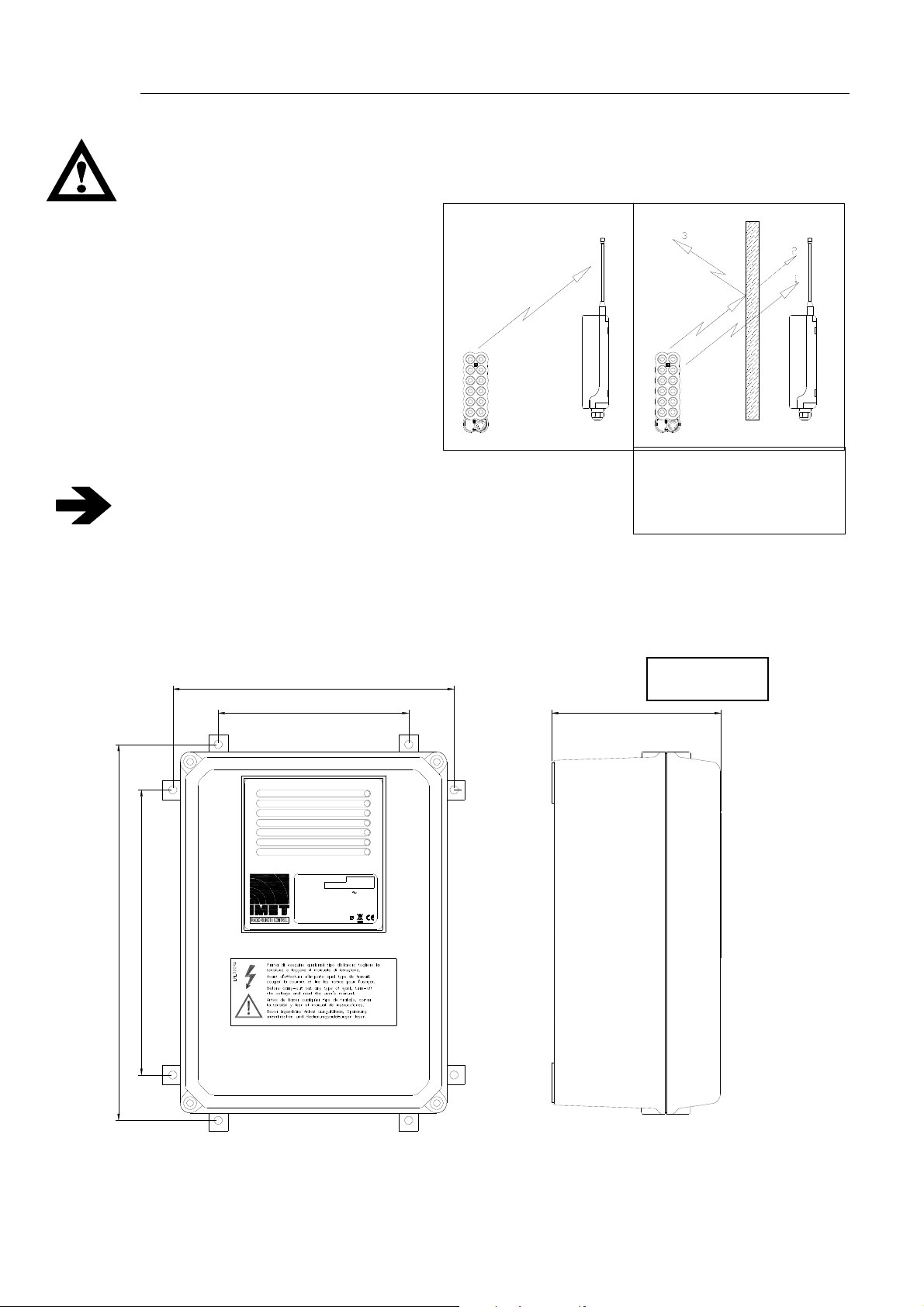
The radio remote control should be installed by qualified personnel only.
Install the receiving unit,or its antenna, in case of versions with an external antenna, in the line
of sight of the transmitting unit, with
no electromagnetic shielding. To
improve the operating range if the
antenna is integrated, do not install
the unit on metal surfaces, if
possible.
F
R
Do not bypass the machine’s safety
systems; follow the manufacturer’s
instructions.
Do not install the receiving unit too high
above the ground (10÷20 metres). At
S
T
P
O
O
P
E
S
T
T
E
R
these heights the unit may receive local
radio signals that can disturb
S
R
E
T
S
E
E
S
T
E
R
RECOMMENDED
transceiving operations.
To prevent water infiltrations, install the receiving unit vertically,
with the cable clamps and any connections at the bottom, as
shown in the figure.
ANTENNA ANTENNA
F
R
S
T
P
O
O
E
P
T
S
T
E
R
S
R
E
T
S
E
E
S
T
E
R
1 Non-attenuating obstacle
2 Partially attenuating
obstacle
3 Shielding obstacle
In case of strong mechanical vibrations, place a rubber shock-absorber between the machine and the
receiver. (dampers).
M-AC receivers and M8 transmitters must be fastened to DIN rails inside a cabinet provided with a
locked door preventing unauthorized access.
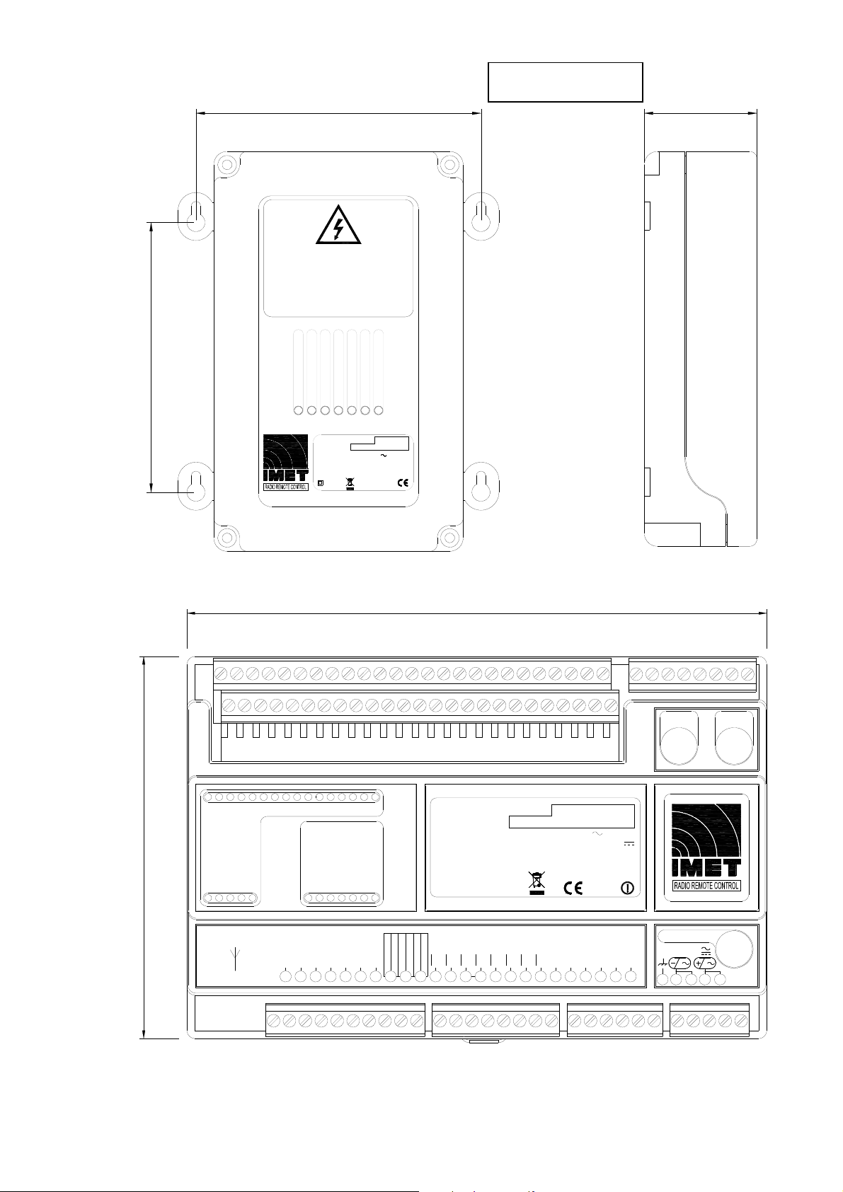
5.1. Receiving unit dimensions and drilling diagram
H version
131
290
220
Data Error ch. B
Passive Emergency ch. B
Data Error ch. A
Passive Emergency ch. A
RF Busy
Power Supply
Working
217
147
RX Unit Mod. M550S HAC
Serial no.
Supply
24/48/55/110/230V 50/60 Hz
Power
Class Protection
Radio Model
M550S - UHF ISM Band
Imax=0.9A 20VA
IP65
LBL550R1
IMET - M550 ALL1-EN 9/53
L and K versions
153
162
Prima di eseguire qualsiasi tipo di lavoro, togliere
la tensione e leggere il ma n uale di istruzione.
Avant d'effectuer n'importe quel type de travail,
couper la courant et lire le notice pour l'usager.
Before carrying-out any type of work, turn-off
the voltage and read the user's manual.
Bevor irgendwelche Arbeit ausgefuehrt wird,
Spannung unterbrechen und
Bedienungsanleitungen lesen.
Data Error ch. A
Data Error ch. B
Passive Emergency ch. B
Passive Emergency ch. A
RF Busy
Power Supply
RX Unit Mod. M550S LAC
Serial no.
Supply
24/48-55/110/230V
Power
Class Protection
Radio Model
Imax=0.9A 20VA
M550S - UHF ISM Band
64
Working
50/60Hz
IP65
The dimensions correspond to 14 mod. DIN.
B1B2B3B4B5B6B7B8A1A2A3A4A5A6A7
A8
120
DATA ERROR CH. A
EMERGENCY CH. A
POWER SUPPLY
EMERGENCY CH. B
DATA ERROR CH. B
AIN1
GND
WORKING
+VIN
TXD
ERROR
C1C2C3C4C5
LB534
ANT
+5V
AIN4
RF BUSY
AIN2
AIN3
182
TRX Unit Mod. M550D MAC
Serial no.
Supply AC 13 - 24V 50/60Hz
Power
Radio Model M550D - UHF ISM Band
LB305
LB306
RTS
RXD
ACK
STROBE
D6
D7
D3
D4
D5
D0
D1
D2
T 5A L250VT 5A L250V
LB309
LB304
13 - 24VSupply DC
1,2A 20VA
0470
T 1.25A L250V
13 - 24V
AD OUT 8
AD OUT 7
AD OUT 6
AD OUT 5
GND
OUT VREF
747372717069686766656463626160595857565554535251
75 767778 79
LN
LB422
10/53 IMET - M550 ALL1-EN
5.2. Connecting the receiver
Do not perform any operation until the equipment is powered off.
The power supply for the radio remote control should be located downstream from the machine’s main
switch.
Connecting to the distribution network directly is prohibited. The network disconnecting
switch foreseen for the distribution network must be equipped w ith a device protecting from
unauthorised closing (padlock
The connection between the receiving unit and the machine should always be REMOVABLE
. If the
connection is made directly on the terminal board inside the machine, a multipolar connector should
be used so that the receiver can be disconnected and the original wired controls restored at any time.
The wire connections between the receiving unit and the machine should respect Standard EN60204.
The wires must have a cross-section of at least 0.75 mm
2
and must be self-extinguishing.
If possible use ferrules for conductor ends, and make sure that the terminals are fastened tightly.
Consult the transmitting unit controls diagram (Annex A) and the receiving unit wiring diagram to
identify the equivalent actuators in the two units.
Be sure to note the supply voltage when connecting the receiving unit.
In versions H-AC and L-AC, the fuse current must be adjusted to the supply voltage.
After installing, test the radio remote control and the machine to make sure they work as
expected. In addition, it is very important to make sure that the STOP circuit works properly.
Pressing the STOP button during normal operation should make the contacts of relays A and B
in the E-STOP circuit open.
Lastly, fill in the sheet showing the connection diagram between the receiving unit and the machine
and write down the date of installation in the box on page 47 of this manual.
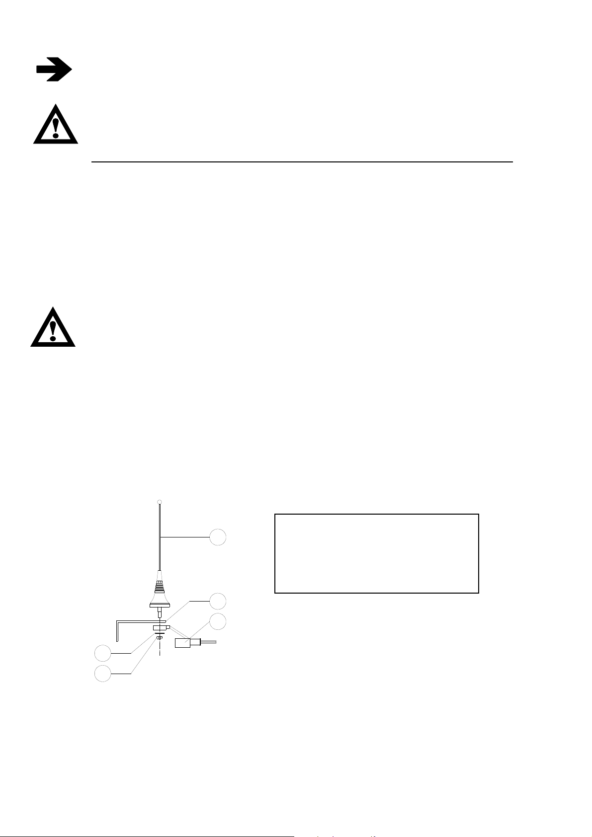
5.2.1. Installing the external antenna
A properly installed antenna is essential for a good operating range. Install the antenna outside at the
highest and most visible point, far from metal structures. Use a tuned antenna only, and connect it to the
receiver using an RG58 coaxial cable (impedance 50Ω). For M550S M8 and M550D M8 type
transmitters only use the antennas supplied by IMET, other types of antenna must be approved in
conformity to the ETSI EN 300 200-2 standard
1
2
SYMBOLS
1 Antenna whip
2 Fastening bracket
3 RG58 cable with protective sheath
4 Washer
5 Locking nut
3
4
5
IMET - M550 ALL1-EN 11/53
5.2.2. STOP (E-STOP)
Connect the contact of the E-STOP circuit so that it commands the coil of the machine’s main line
contactor, and remember that the maximum allowable current is 5A.
Attention: The E-STOP circuit has been designed for category 4 UNI EN 954-1 standard and/or
PLe according to the ISO13849-1 standard. In order to keep this safety category, the relays
must be connected in series (pre-cable standard configuration by IMET) or in parallel ONLY to
manage interruption of the main power supply line (See Example 2).
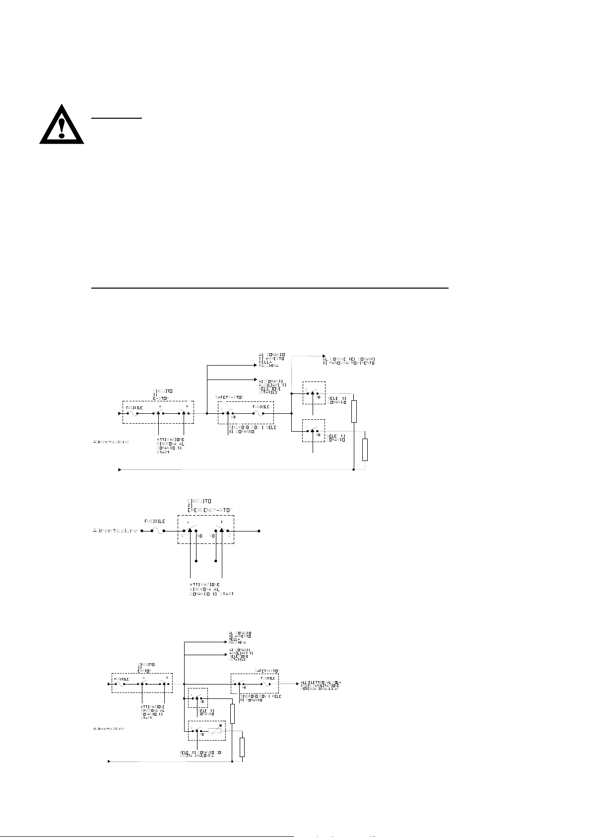
5.2.3. Safety STOP (S-STOP)
The Safety Stop is an additional safety function. It consists in relay inside the receiver monitored by
the RX logic that can be associated with the commands sent by the transmitter and which in case of
problems automatically stops the receiver, as shown by the status LEDs.
Example 1 (in series to control commands): The Safety Stop introduces a redundancy which activates
the safety function in case the control command relays fail to open.
Example 2 (operating the bypass valve): The Safety Stop can command the drain valve in a hydraulic
machine so that the machine is powered only when a control command is given.
The Safety Stop must not be associated with the bistable selection controls
The risk analysis and safety class are based on Standard UNI EN 954-1 and ISO 13849-1 . The safety
class of each control is shown in Annex B. Take good notice of the maximum currents allowable on
the relay contacts (see Chap. 10).
Example of wiring of Safety-Stop relay for AC applications
Alternative for special applications (for L-AC receivers only)
Example of wiring of Safety-Stop relay for DC applications
12/53 IMET - M550 ALL1-EN
5.3. Basic functions
The table below shows the basic functions available on almost all receivers.
Relay Function Typical Uses Remarks
T-STOP The relay is activated for 5 seconds from the moment
the radio remote control is switched off or enters
passive emergency mode.
The T-STOP can be activated at switch-off or with a 2
• Delayed STOP of
combustion engine
• Engine deceleration
second delay.
S-STOP The relay is activated only by an instable command
from a toggle switch, button or joystick
Connected in series
, the function introduces a
redundancy that can be used to increase function
• Enables the drain valve
• Common enabling of control
commands
Relays constantly
monitored by uP.
Opens with a 0.8
second delay
safety
E-STOP The two relays are activated when the radio remote
control is switched on (STOP RELAY cat. 4 UNI
EN954-1 e PL e ISO13849-1) and stay active until a
STOP command intervenes (pressing the STOP
button or passive emergency)
• Powers the main contactor
in the machine’s control box
• Common power supply for
control commands
• Machine power supply
HORN Horn control relay Warns of potentially hazardous
situations
Relays constantly
monitored by uP
it can be associated
to the first START
START START control relay Powers the machine’s control box
and enables machine Start
function
LAMP Blinker control relay Blinker power supply
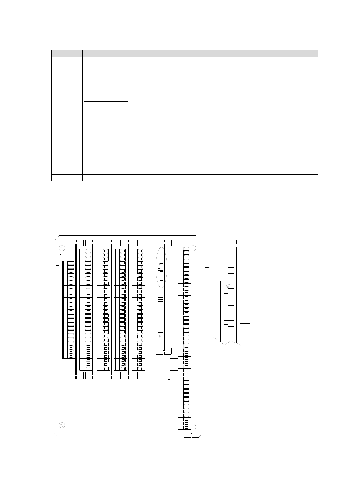
5.4. Connection diagrams of H receivers
Receiving unit version H is provided with 7 slots where the control relay cards, the analogue output
cards and the data feedback card are plugged in. Slot A includes, as well as the group A controls, the
basic functions in the table above.
LOGICA
+
SLOT F
SLOT E
SLOT D
SLOT B
RADIOSLOT C
SLOT A
AD5AD6AD7AD8AD1 AD2 AD3 AD4
C
NC
10
89
7
6
5
4
3
12
10
NO
NC
NO
C
89
NC
NO
C
NC
NO
C
67
NC
NO
C
5
NC
NO
C
43
NC
NO
C
NC
NO
C
21
NC
NO
C
NC
NO NO
NC
NO
NC
NO
NC
NO
NC
NO
NC
NO
NC
NO
NC
NO
NC
NO
NC
NO
NC
C
C
C
C
C
C
C
C
C
C
C
NC
106
NO
C
NC
NO
C
89
NC
NO
C
7
NC
NO
C
NC
NO
C
5
NC
NO
C
41
NC
NO
C
3
NC
NO
C
2
NC
NO
C
NC
NO
C
NC
10
NO
CC
NC
NO
C
89
NC
NO
C
7
NC
NO
C
6
NC
NO
C
5
NC
NO
C
NC
NO
C
3
NC
NO
C
214
NC
NO
C
NC
NO
C
NC
A8
NO
C
NC
A7
NO
C
NC
A6
NO
C
NC
A5
NO
C
NC
A4
NO
C
NC
A3
NO
C
NC
A2A1
NO
C
NC
NO
C
NC
NO
C
NO
NO
S-STOP T-STOP
C
C
C
NO
NO
NO
C
NC
NO
C
NC
START HORN E-STOP E-STOP
NO
C
NC
LAMP
NO
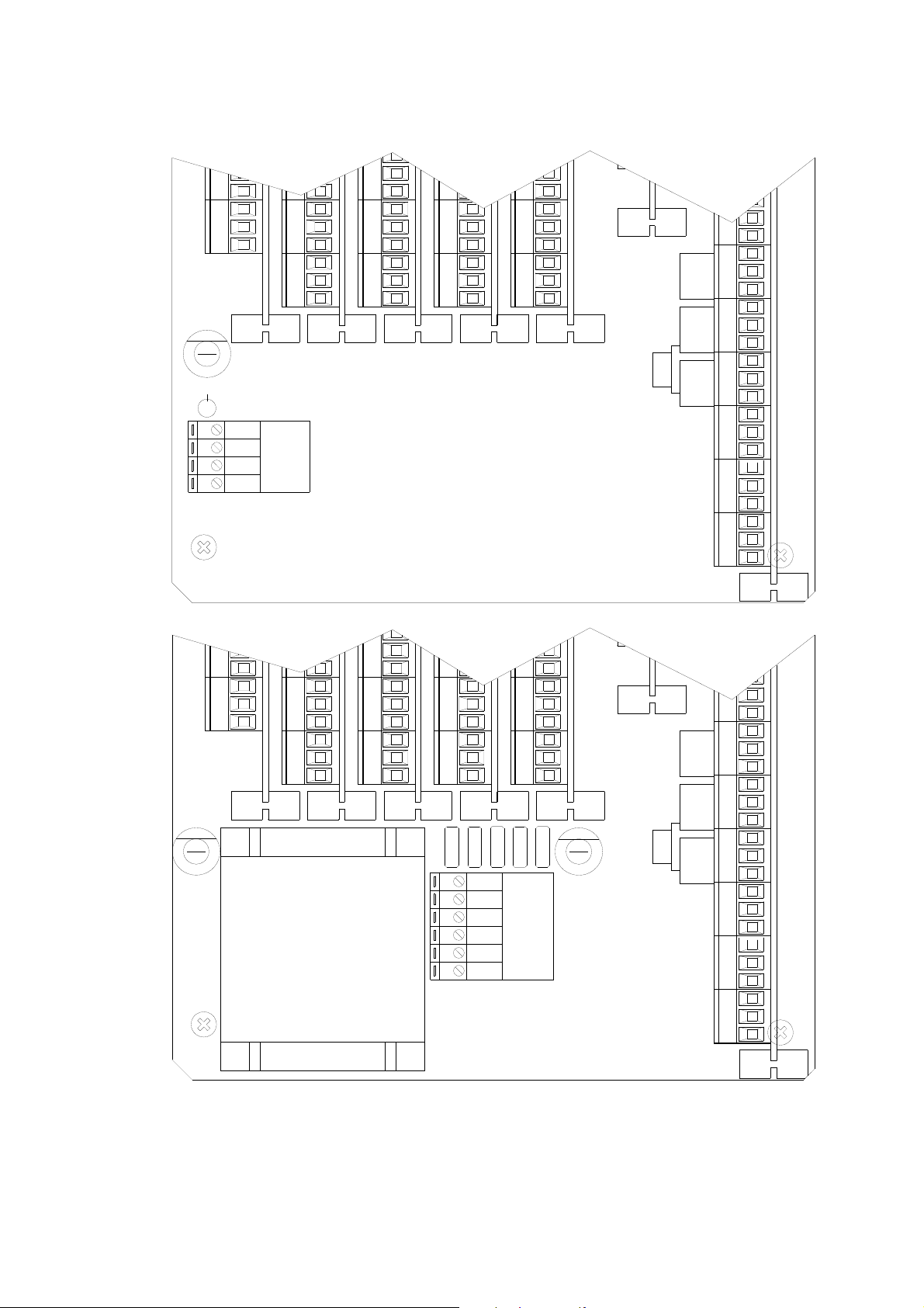
In its basic configuration the receiving unit
is supplied with a relay card (on slot A)
and a logic board.
Depending on project specifications, units
may include cards for control groups B, C,
D, E, an analog output card and, in case
of dual transmission, a data feedback
card
Note: On each project the controls are
based on a unique configuration that may
DATA ERROR CH. B
PASSIVE EMERGENCY CH. B
DATA ERROR CH. A
PASSIVE EMERGENCY CH. A
RF BUSY
POWER SUPPLY
WORKING
be changed only by IMET.
IMET - M550 ALL1-EN 13/53
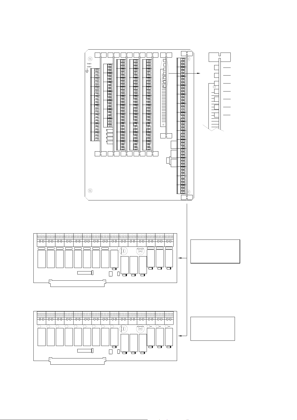
5.4.1. H receiver with analog output card and data feedback card
LOGICA
+
SLOT F
SLOT E
SLOT D
SLOT B
RADIOSLOT C
SLOT A
C
C
NC
10
D0
NO
D1
C
D2
NC
D3
NO
D4
C
D5
89
NC
D6
NO
D7
C
STB
NC
VIN
NO
ACK
C
ERR
67
AD0
AD1
AD2
AD3
GND
+5V
GND
GND
GND
NC
NO
C
5
NC
NO
C
43
NC
NO
C
NC
NO
C
21
NC
NO
C
NC
NO
AD5 AD6 AD7 AD8AD1 AD2 AD3 AD4
C
NC
NC
106789
10
NO
NO
C
C
NC
NC
NO
NO
C
C
89
NC
NC
NO
NO
C
C
7
NC
NC
NO
NO
C
C
6
NC
NC
NO
NO
C
C
5
52341
NC
NC
NO
NO
C
C
NC
NC
NO
NO
C
C
3
NC
NC
NO
NO
C
C
214
NC
NC
NO
NO
C
C
NC
NC
NO
NO
C
NC
A8
NO
C
NC
A7
NO
C
NC
NO
C
NC
A5A4A3 A6
NO
C
NC
NO
C
NC
NO
C
NC
A2A1
NO
C
NC
NO
C
NC
NO
C
NO
NO
S-STOP T-STOP
C
C
C
NO
NO
NO
C
NC
NO
C
NC
START HORN E-STOP E-STOP
NO
C
NC
LAMP
NO
DATA ERROR CH. B
PASSIVE EMERGENCY CH. B
DATA ERROR CH. A
PASSIVE EMERGENCY CH. A
RF BUSY
POWER SUPPLY
WORKING
C
NC
A8 A7 A6 A5 A4 A3 A2 A1
C
NC
C
NO NO
NC
NC
NO
C
NC
NC
NO
A6 A3A4
NC
NC
NO
NO
NO
C
C
NC
NC
NO
NO
NO
A5
NC
NC
NO
NO
C
C
NC
NC
NO
NO
C
C
C
C
C
C
C
NC
NC
NO
NO
T-STOP S-STOP E-STOP E-STOP HORN START LAMP
C
C
NC
NC
NO
NO
A1A2A7A8
NC
NC
NO
NO
C
C
NC
NC
NO
NO
NC
NC
NO
C
C
NC
NC
NO
C
C
C
C
C
C
C
NC
NC
NO
NO
NO
Version for H-AC
receiver
IMET RADIO REMOTE CONTROLM550RST REV00
C
C
NC
NC
NO
NO
NO
LAMPSTARTHORNE-STOPE-STOPS-STOPT-STOP
Version for HDC receiver
IMET RADIO REMOTE CONTROLM550RSA REV02
14/53 IMET - M550 ALL1-EN
5.4.2. Power supply connections of H-DC and H-AC receivers
NC
NO
F1
1.25AT
+
+
-
-
C
21
NC
NO
C
NC
POWER IN
13 - 24 VDC
C
NC
NO
C
12
NC
NONO
C
NC
NO
C
12
NC
NO
C
NC
NO
C
12
NC
NO
NO
C
NO
NO
S-STOP
C
C
C
E-STOPE-STOPHORNSTART
NO
NO
NO
C
NC
NO
C
NC
NO
C
NC
LAMP
NO
F1
1.25AT
AD1 AD1
NC
NO
C
NC
NO
C
12
NC
NO NO
C
21
NC
NO
C
NC
C
21
NC
NO
C
NC
NO
230V
110V
55V
48V
24V
C
21
NC
NO
C
NC
NO
F2
24-55VAC 1.25AT
110-230VAC 0.63AT
AC
POWER INPUT
N
NO
C
NO
NO
S-STOP
C
C
C
NO
NO
NO
C
NC
NO
C
NC
START HORN E-STOP E-STOP
NO
C
NC
LAMP
NO
IMET - M550 ALL1-EN 15/53
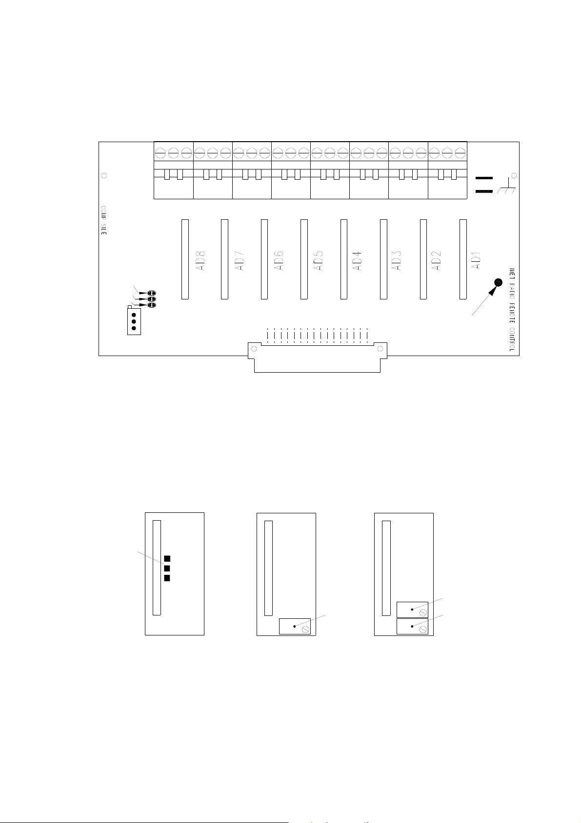
5.4.3. Analog command card
* IN AD8
371 - 1000Hz
131 - 370Hz
50 - 130Hz
* IN AD1, ... ,8 COLLEGATO SOLO PER PWM
T3
T2
JUMPER FREQ. SEL.
T1
FREQ. REG. (PWM)
FOR M550C1
USED ONLY FOR PWM OUTPUT
* IN AD7
OUT AD7
GND
OUT AD8
GND
Control modules
* IN AD6
OUT AD6
GND
* IN AD5
OUT AD5
GND
* IN AD4
OUT AD4
GND
* IN AD3
OUT AD3
GND
* IN AD2
* IN AD1
GND
OUT AD1
OUT AD2
TEST POINT PER
TARATURA FREQUENZA
GND
M550C2: 0-20mA/4-20mA current-operated control
M550C1: PWM current-operated control
M550V: voltage-operated control
M550C2
RANGE SEL.
ANALOG CARD
M550C1 (PWM)
ANALOG CARD
GAIN REG.
M550V SERIES
ANALOG CARD
Vout MAX REG.
Vout MIN REG.
16/53 IMET - M550 ALL1-EN
 Loading...