


DG4P
ISTRUMENTI MISURE ELETTR ICHE SpA
ISTRUMENTI MISURE ELETTR ICHE SpA
ISTRUMENTI MISURE ELETTR ICHE SpA
DG4P
DG4Q
DG4Q
RM3C
RM3C
Via Travaglia 7
20094 CORSICO (MI)
ITALIA
T el. 02 44 878.1
Fax 02 45 03448
+39 02 45 86 76 63
www.imeitaly .com
info@imeitaly.it
Istruzioni d’Uso
User’ s Guide
Guide d’utilisation
Bedienungsanleitung
10780631 • 07-2003 3aEd.

SUPPLY
INPUT
20
21
1
2
(+)
(-)
+
+
3
4
+
+
5
SENSOR OUTPUT
24
23
-
+
(option)
1
5
+
2
5
+
3
5
+
4
3
+
5
4
5
+
Ch1 200V
Ch2 20V
Ch3 200mV
Ch4 20mA
Ch5 2mA
DG4P • DG4Q 96 x 48mm DIN43700
SUPPLY
INPUT
20
21
1
2
14
16
15
2
17
18
1
19
(+)
(-)
+
+
3
4
+
+
5
SENSOR
OUTPUT
24
23
-
+
(option)
1
5
+
2
5
+
3
5
+
4
3
+
5
4
5
+
Ch1 200V
Ch2 20V
Ch3 200mV
Ch4 20mA
Ch5 2mA
SUPPLY
INPUT
20
21
1
2
14
16
15
2
17
18
1
19
(+)
(-)
+
+
3
4
+
+
5
1
5
+
2
5
+
3
5
+
4
3
+
5
4
5
+
Ch1 200V
Ch2 20V
Ch3 200mV
Ch4 20mA
Ch5 2mA
100
110
75
5
35
1
S 305/138
S 305/139
RM3C 100 x 110mm
S 260/14
RM3C

10780631 • 07-2003 3 Ausgabe 10780631 • 07-2003 3aEd.
2
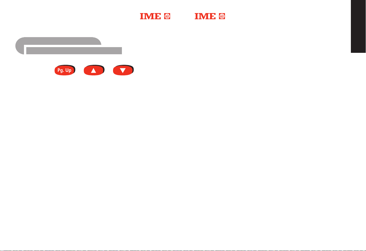
210 Am Display erscheint rEL
221 Durch Drücken von
a Wenn der angezeigte Typ der gewünschte ist, drücken Sie PgUp
um die Programmierung fortzusetzen
b Wenn Sie den Typ ändern wollen, können Sie mit der Taste
den gewünschten Typ wählen und mit PgUp abschließen.
230 Am Display erscheint SEt
241 Durch Drücken von
(Alarmschwelle)
a Wenn der angezeigte Wert der gewünschte ist, drücken Sie
PgUp um die Programmierung fortzusetzen
b Wenn Sie den Wert ändern wollen, können Sie mit den Tasten
und ▼den gewünschten Wert einstellen und mit PgUp abschließen.
250 Am Display erscheint HYS
261 Durch Drücken von
a Wenn der angezeigte Wert der gewünschte ist, drücken Sie
PgUp um die Programmierung fortzusetzen
b Wenn Sie den Wert ändern wollen, können Sie mit den Tasten
und ▼den gewünschten Wert einstellen und mit PgUp abschließen.
270 Am Display erscheint dEL
281 Durch Drücken von
a Wenn der angezeigte Wert der gewünschte ist, drücken Sie
PgUp um die Programmierung fortzusetzen
b Wenn Sie den Wert ändern wollen, können Sie mit den Tasten
und ▼den gewünschten Wert einstellen und mit PgUp abschließen.
290 Am Display erscheint End, drücken Sie gleichzeitig
Programmierung zu bestätigen
300 Am Display erscheint Sto; das Gerät speichert die Einstellung und
verläßt das Menü. ■
▲
, erscheint am Display der Relaistyp.
(siehe Punkt 23)
▲
, erscheint am Display der Grenzwert
▲
, erscheint am Display die Hysterese (Schaltschwelle)
▲
, erscheint am Display die eingestellte verzögerung.
(siehe Punkt 25)
(siehe Punkt 27).
(siehe Punkt 29).
▲▼
um die
▲
▲
▲
▲
Indice
Istruzioni per l’installazione 2
Descrizione frontale 3
Parametri programmabili 4
Visualizzazione 5
Programmazione 6
Allarmi 11
Italiano
I.M.E. S.p.A. si riserva in qualsiasi momento, di modificare le caratteristiche tecniche senza darne preavviso.

10780631 • 07-2003 3aEd. 10780631 • 07-2003 3 Ausgabe
3
Istruzioni per l’installazione
La posizione di fissaggio (grado di inclinazione) risulta completamente
indifferente ai fini del funzionamento.
Prima di procedere all’installazione, accertarsi che i dati di targa corrispondano
a quelli richiesti (tipo di ingresso, valore di alimentazione ausiliaria, ecc.).
Nei cablaggi rispettare scrupolosamente lo schema di inserzione, una inesattezza nei collegamenti è inevitabile causa di misure falsate o di danni allo
strumento.
Nei collegamenti evitare di disporre i cavi parallelamente a conduttori di
potenza o in prossimità di sorgenti di campi elettromagnetici intensi
(es. grossi trasformatori, teleruttori, ecc.).
Per l’ingresso di misura utilizzare preferibilmente cavi schermati.
Nei modelli DG4P2 • DG4Q2 (con allarmi) • RM3C la posizione dei contatti
indicata nello schema, si riferisce allo strumento non alimentato. ■
Alarmas
In den Menüs AL.1 und AL.2 können zwei Alarme parametriert werden.
Für jeden Alarm können Sie einstellen:
• tYP ALARMTYP
• rEL AUSGANGSRELAIS
• SEt SCHWELLE
• HYS HYSTERESE
• dEL EINSATZVERZÖGERUNG
180 Drücken Sie solange auf PgUp bis AL.1 dargestellt wird
190 Drücken Sie gleichzeitig
201 Durch Drücken von
Hi = max. oder
Lo = min.
n.E = normalerweise angezogen oder
n.d = normalerweise abgefallen
-1999…1999 (DG4P - RM3C)
0...9999 (DG4Q)
-1999…1999 (DG4Q)
0...9999
0…60 = 0…60 Sekunden
▲▼
Am Display erscheint PAS und danach Typ
▲
erscheint am Display der Alarmtyp
(Hi max., Lo min.)
a Wenn der angezeigte Typ der gewünschte ist, drücken Sie PgUp
um die Programmierung fortzusetzen
b SWenn Sie den Typ ändern wollen, können Sie mit der Taste
den gewünschten Typ wählen und mit PgUp abschließen.
(siehe Punkt 21).
▲
Deutsch
1111
H

10780631 • 07-2003 3 Ausgabe 10780631 • 07-2003 3aEd.
4
151 Durch Drücken von ▲, erscheint am Display der Endwert des Anzeige-
bereiches.
a Wenn der angezeigte Wert der gewünschte ist, drücken Sie
PgUp um die Programmierung fortzusetzen (siehe Punkt 16)
b Wenn Sie den Wert ändern wollen, können Sie mit den Tasten
und ▼den gewünschten Wert einstellen und mit PgUp
abschließen.
160 Am Display erscheint End; drücken Sie gleichzeitig ▲▼um die
Programmierung zu bestätigen.
170 Am Display erscheint Sto; das Gerät speichert die Einstellung und
verläßt das Menü. ■
▲
Descrizionee frontale
1 • FRONTALE PROTEZIONE IP50 EN60529 (DG4P/DG4Q)
In opzione è disponibile protezione frontale IP54.
2 • DISPLAY
Display a LED rossi, massima indicazione –1999…1999 (DG4P/RM3C) e
0…9999 (DG4Q).
3 • TASTIERA
3 tasti utilizzati per la configurazione oppure la selezione della visualizzazione
(valore istantaneo, valor
e di picco, stato allarmi).
Italiano
33
4 • LED SEGNALAZIONE ALLARMI
L’accensione indica l’avvenuto intervento di uno o di entrambi gli allarmi
(entrando nel menù è possibile visualizzar
uno o entrambi i relè sono in condizione di anomalia).
Al rientro dalla condizione di anomalia/e, il LED si spegne automaticamente.
5 • ETICHETTA ADESIV
Personalizzabile dall’utente.
Con lo strumento vengono fornite 18 etichette adesive con le unità ingegneristiche più comuni. ■
A UNITA’ INGEGNERISTICA
e lo stato allarmi, verificando se

10780631 • 07-2003 3aEd. 10780631 • 07-2003 3 Ausgabe
5
5
ANZEIGE
Parametri programmabili
InP / canale d’ingresso (portata)
La scelta del canale di ingresso (e quindi della portata) viene effettuata su
due livelli, connessione (morsetti d’ingresso) e attraverso la programmazione
da tastiera.
• I canali di ingresso disponibili sono 5
Ch1 portata 200V (Un)
Ch2 portata 20V (Un)
Ch3 portata 200mV (Un)
Ch4 portata 20mA (In)
Ch5 portata 2mA (In)
dSP / campo di misura e visualizzazione
Permette di selezionare (all’interno della portata scelta) gli effettivi valori
del campo di misura e di associare loro la visualizzazione desiderata.
• Inizio campo di misura
•
Fine campo di misura
• Visualizzazione corrispondente all’inizio del campo di misura
• Visualizzazione corrispondente alla fine del campo di misura
• Punto decimale (XX.XX oppure XXX.X oppure XXXX)
AL.1 • AL.2 / allarmi
• Tipo minima o massima
• Stato relè normalmente eccitato o diseccitato
• Soglia -1999…1999 digit - 0...9999 (DG4Q)
• Isteresi (punto di ripristino) -1999…1999 digit - 0...9999 (DG4Q)
• Ritardo intervento 0…60 secondi. ■
40 Drücken Sie PgUp; am Display erscheint InP
50 Drücken Sie noch einmal PgUp; am Display erscheint dSP
60 Drücken Sie gleichzeitig
Am Display erscheint PAS und danach L.In (Beginn des Meßbereiches)
71 Durch Drücken von ▲erscheint am Display der Anfangswert des
Meßbereiches.
a Wenn der angezeigte Wert der gewünschte ist, drücken Sie
PgUp um Programmierung fortzusetzen (siehe Punkt 8)
b Wenn Sie den Wert ändern wollen, können Sie mit den Tasten
und ▼den gewünschten Wert einstellen und mit PgUp abschließen
dann drücken Sie PgUp
80 Im Display erscheint H.In (Ende des Meßbereiches).
91 Durch Drücken von ▲, erscheint am Display der Endwert des
Meßbereiches.
a Wenn der angezeigte Wert der gewünschte ist, drücken Sie
PgUp um Programmierung fortzusetzen (siehe Punkt 10).
b Wenn Sie den Wert ändern wollen, können Sie mit den Tasten
und ▼den gewünschten Wert einstellen und mit PgUp abschließen.
100 Im Display erscheint dP. (Komma).
111 Durch Drücken von ▲erscheint am Display der Dezimalpunkt.
a Wenn die Kommastellung die gewünschte ist, drücken Sie PgUp
um die Programmierung fortzusetzen (siehe Punkt 12)
b Wenn Sie das Komma ändern wollen, können Sie mit der Taste
die gewünschte Stellung auswählen und mit PgUp abschließen.
120 Im Display erscheint L.dS (Anfang des Anzeigebereiches)
131 Durch Drücken von ▲erscheint am Display der Anfangswert des
Anzeigebereiches.
a Wenn der angezeigte Wert der gewünschte ist, drücken Sie
PgUp um die Programmierung fortzusetzen (siehe Punkt 14)
b Wenn Sie den Wert ändern wollen, können Sie mit den Tasten
und ▼den gewünschten Wert einstellen und mit PgUp abschließen.
140 Im Display erscheint H.dS (Ende des Anzeigebereiches)
▲▼
▲
▲
▲
▲
Deutsch
Deutsch
99
H

10780631 • 07-2003 3 Ausgabe 10780631 • 07-2003 3aEd.
6
BEREICH
Hier wird der benötigte Meßbereich festgelegt: 5 Bereiche (Kanäle) sind
verfügbar
Visualizzazione
Italiano
55
Ch1 Bereich 200 für Eingänge zwischen
-50…50V und -200…200V (DG4P, RM3C)
0…50V und 0…200V (DG4Q)
Ch2 Bereich 20V für Eingänge zwischen
-5…5V und -20…20V oder 1…5V (DG4P, RM3C)
0…5V und 0…20V oder 1…5V (DG4Q)
Ch3 Bereich 200mV für Eingänge zwischen
-50…50mV und -200…200mV (DG4P, RM3C)
0…50mV und 0…200mV (DG4Q)
Ch4 Bereich 20mA für Eingänge zwischen
-5…5mA und -20…20mA oder 4…20mA (DG4P, RM3C)
0…5mA und 0…20mA oder 4…20mA (DG4Q)
Ch5 Bereich 2000µA (2mA) für Eingänge zwischen
-500…500µA und -2000…2000µA (DG4P, RM3C)
0…500µA und 0…2000µA (DG4Q)
ACHTUNG:
Die Programmierung des Kanals Ch5 (2mA) wird in µA (2000µA) ausgedrückt
Der Meßbereich wird sowohl durch die Programmierung als auch durch den
Anschluß festgelegt (siehe Anschlußbild).
10 Drücken Sie PgUp; Am Display erscheint InP. Drücken Sie gleichzeitig
Am Display erscheint PAS und danach Ch.1 (oder der gespeicherte Kanal).
20 Drücken Sie solange auf PgUp bis der gewünschte Kanal dargestellt
wird. Drücken Sie noch einmal PgUp, um End darzustellen.
30 Drücken Sie gleichzeitig ▲▼. Am Display erscheint Sto; das Gerät spei-
chert die Einstellung und verläßt das Menü.
▲▼
Oltre al valore istantaneo misurato, è possibile visualizzare il valore massimo
letto (picco massimo) e lo stato degli allarmi (“On” = condizione di allarme
oppur
e “OFF” = condizione di sorveglianza).
VALORE DI PICCO
Durante il normale funzionamento, premendo il tasto
il valore massimo misurato.
Tenendo premuto il tasto
del valore di picco “rS.P”.
L
’azzeramento avviene automaticamente anche allo spegnimento dello
strumento (assenza alimentazione ausiliaria) oppure al cambiamento della programmazione del segnale di ingresso o della visualizzazione.
SEGNALAZIONE ALLARMI
Al superamento di una o di entrambe le soglie predisposte, avviene l’accensione del led “AL”.
Pr
emere ripetutamente PgUp fino a visualizzare rL.A
Premere contemporaneamente
Sul display appare PAS seguito da AL.1
Premendo
On = condizione di allarme in corso
OFF = condizione normale
Pr
emendo PgUp viene visualizzato AL.2
Premendo
On = condizione di allarme in corso
OFF = condizione normale
Premendo PgUp viene visualizzato End
Premere contemporaneamente
Sul display appare Sto e lo strumento esce automaticamente dalla programmazione. ■
H
▲
viene visualizzato lo stato dell’allarme 1
▲
viene visualizzato lo stato dell’allarme 2
▲
per 5 secondi circa, si effettua l’azzeramento
▲▼
.
▲▼
.
▲
è possibile visualizzare

10780631 • 07-2003 3aEd. 10780631 • 07-2003 3 Ausgabe
7
Beispiel Eingang – 150…0…150V entsprechend – 16,50…0…16,50kW
Programmazione
Grazie ai menù InP e dSP è possibile selezionare il valore del segnale da
misurare e la corrispondente visualizzazione.
La programmazione avviene su tre fasi successive:
Canale di ingresso • Campo di misura • Visualizzazione
1 • Canale di ingresso
Selezionare il canale entro i cui valori è compreso il segnale da misurare
Menù InP
Ch. canale di ingresso
2 • Campo di misura
Programmare gli esatti valori di inizio e fine campo di misura (inizio e fondo scala)
Menù dSP
L.In valore inizio campo di misura
H.In valore finale campo di misura
3 • Visualizzazione
Programmare i valori da visualizzare in corrispondenza del campo di misura
Menù dSP
dP. punto decimale visualizzazione
L.dS valore da visualizzare in corrispondenza dell’inizio del
campo misura (L.In)
H.dS valore da visualizzare in corrispondenza della fine del
campo misura (H.In)
Ch. = Ch.1 (-200…0…200V)
L.In = -150,0
H.In = 150,0
dP. = 0,00
L.dS = -16,50
H.dS = 16,50
Beispiel Eingang 0…8,5V entsprechend 0…1250 Umdrehungen pro Minute
Ch. = Ch.2 (-20…0…20V)
L.In = 0,00
H.In = 8,50
dP. = 000
L.dS = 0000
H.dS = 1250
Beispiel Eingang – 60…0…60mV entsprechend – 1800…0…1800A
Ch. = Ch.3 (-200…0…200mV)
L.In = -60,0
H.In = 60,0
dP. = 000
L.dS = -1800
H.dS = 1800
Beispiel Eingang 4…20mA entsprechend – 100,0…100,0 kg
Ch. = Ch.4 (-20…0…20mA)
L.In = 4,00
H.In = 19,99
dP. = 00,0
L.dS = -100,0
H.dS = 100,0
H
Deutsch
77
H
10780631 • 07-2003 3 Ausgabe 10780631 • 07-2003 3aEd.
8
Esempio ingresso –150…0…150V corrispondenti a –16,50…0…16,50kW
Programmierung
Durch die Menüs InP und dSP ist es möglich den Signalwert zu messen
und die entsprechende Anzeige zu wählen.
Die Programmierung erfolgt in drei Schritten:
Eingangskanal • Meßbereich • Anzeige.
1 • Eingangskanal
Wählen Sie den Kanal, der dem zu messenden Eingangssignal entspricht.
Menü InP
Ch. Eingangskanal
2 • Meßbereich
Programmieren Sie den entsprechenden Anfangs- und Endwert des Meßsignals
(Beginn- und Endskala)
Menü dSP
L.In Beginnwert des Meßbereiches
H.In Endwert des Meßbereiches
3 • Anzeige
Programmieren Sie den gewünschten Anfangs- und Endwert des Anzeigebereiches.
Menü dSP
dP. Dezimalpunkt
L.dS Anfangswert des Anzeigebereiches entsprechend dem
Anfangswert des Meßbereiches. (L.In)
H.dS Endwert des Anzeigebereiches entsprechend dem
Endwert des Meßbereiches. (H.In)
Esempio ingresso 0…8,5V corrispondenti a 0…1250 giri/min
Esempio ingresso –60…0…60mV corrispondenti a –1800…0…1800A
Esempio ingresso 4…20mA corrispondenti a –100,0…100,0 kg
H
Ch. = Ch.1 (-200…0…200V)
L.In = -150,0
H.In = 150,0
dP. = 0,00
L.dS = -16,50
H.dS = 16,50
Ch. = Ch.2 (-20…0…20V)
L.In = 0,00
H.In = 8,50
dP. = 000
L.dS = 0000
H.dS = 1250
Ch. = Ch.3 (-200…0…200mV)
L.In = -60,0
H.In = 60,0
dP. = 000
L.dS = -1800
H.dS = 1800
Ch. = Ch.4 (-20…0…20mA)
L.In = 4,00
H.In = 19,99
dP. = 00,0
L.dS = -100,0
H.dS = 100,0
Italiano
77
H

10780631 • 07-2003 3aEd. 10780631 • 07-2003 3 Ausgabe
9
PORTATA
Permette di selezionare la portata desiderata, sono disponibili 5 portate (canali)
Ch1 portata 200V per ingressi compresi tra
-50…50V e -200…200V (DG4P, RM3C)
0…50V e 0…200V (DG4Q)
Ch2 portata 20V per ingressi compresi tra
-5…5V e -20…20V opp. 1…5V (DG4P, RM3C)
0…5V e 0…20V opp. 1…5V (DG4Q)
Ch3 portata 200mV per ingressi compresi tra
-50…50mV e -200…200mV (DG4P, RM3C)
0…50mV e 0…200mV (DG4Q)
Ch4 portata 20mA per ingressi compresi tra
-5…5mA e -20…20mA opp. 4…20mA (DG4P, RM3C)
0…5mA e 0…20mA opp. 4…20mA (DG4Q)
Ch5 portata 2000µA (2mA) per ingressi compresi tra
-500…500µA e -2000…2000µA (DG4P, RM3C)
0…500µA e 0…2000µA (DG4Q)
ATTENZIONE:
La programmazione del canale Ch5 (2mA) é espressa in µA (2000µA)
La selezione della portata deve essere effettuata sia tramite programmazione
da tastiera, sia attraverso la connessione dei morsetti d’ingresso (vedi schema).
10 Premere PgUp sul display appare InP
Premere contemporaneamente
Sul display appare PAS seguito da Ch.1 (o dal canale memorizzato)
20 Agire ripetutamente su PgUp fino a visualizzare il canale desiderato.
Premere ancora una volta PgUp per far apparire End
30 Premere contemporaneamente ▲▼sul display appare Sto lo strumento
memorizza l’impostazione ed esce automaticamente dal menù di programmazione.
▲▼
H
Anzeige
Außer dem gemessenen Momentanwert, ist es möglich den Höchstwert
(Höchstspitze) und den Alarmzustand ("On“ oder "OFF“) darstellen.
HÖCHSTSWERT
Während der normalen Anzeige kann durch Drücken die Taste
ne Maximalwert angezeigt werden.
Durch Halten der Taste
rücksetzen “rS.P”.
Die Rücksetzung erfolgt automatisch auch beim Ausschalten des Gerätes
(keine Hilfsspannung) oder bei der Änderung der Eingangssignalprogrammierung oder der Anzeige.
WARNMELDUNG
Bei der Überschreitung einer oder beider eingestellten Alarmschwellen,
schaltet die LED "AL“ ein.
Drücken Sie wiederholt die Taste PgUp bis rL.A dargestellt wird.
Drücken Sie gleichzeitig die T
Am Display erscheint PAS und danach AL.1.
Durch Drücken der Taste
On = Auslösung
OFF = Ruhezustand
Am Display erscheint PgUp und danach AL.2.
Durch Drücken der T
On = Auslösung
OFF = Ruhezustand
Dur
ch Drücken der Taste PgUp erscheint End im Display.
Drücken Sie gleichzeitig die Tasten
Am Display erscheint Sto und das Menü wird verlassen. ■
▲
für ungefähr 5 Sekunden kann man den Spitzenwert
asten
▲▼
▲
wird der Alarmzustand 1 dargestellt.
aste
▲
wird der Alarmzustand 2 dargestellt.
▲▼
.
▲
der gemesse-
Deutsch
55

10780631 • 07-2003 3 Ausgabe 10780631 • 07-2003 3aEd.
10
VISUALIZZAZIONE
Programmierbare Parameter
InP / Eingangskanal (Bereich)
Die Wahl des Eingangskanals (und daher des Bereiches) iwird durch zwei
Einstellungen getroffen: Verbindung (Eingangsklemmen) und durch die
Tastaturprogrammierung.
• Es gibt 5 verfügbare Eingangskanäle
Ch1 Bereich 200V (Un)
Ch2 Bereich 20V (Un)
Ch3 Bereich 200mV (Un)
Ch4 Bereich 20mA (In)
Ch5 Bereich 2mA (In)
dSP / Meßbereich und Anzeige
Hier werden die tatsächlichen Meßbereichsendwerte und die
Anzeigebereiche eingestellt (im jeweils gewählten Eingangskanal).
• Meßbereichsbeginn
• Meßbereichsende
•
Anzeige entsprechend dem Meßbereichsbeginn
• Anzeige entsprechend dem Meßbereichsende
• Dezimalpunkt (XX.XX oder XXX.X oder XXXX)
AL.1 • AL.2 / Alarme
• Typ min. oder max.
• Relaiszustand normalerweise angezogen oder abgefallen
• Schwelle -1999…1999 digit - 0...9999 (DG4Q)
• Hysterese (Wiederanlaufspunkt) -1999…1999 digit - 0...9999 (DG4Q)
• Einsatzverzögerung 0…60 Sekunden. ■
40 Premere PgUp sul display appare InP
50 Premere nuovamente PgUp sul display appare dSP
60 Premere contemporaneamente
Sul display appare PAS seguito da L.In (inizio campo misura)
71 Premendo una volta ▲sul display viene visualizzato il valore di inizio
del campo di misura.
a Se il valore visualizzato corrisponde a quello desiderato, premere
PgUp e continuare la programmazione (vedi p.to 8)
b Se si desidera modificare il valore, agire su ▲oppure ▼fino ad
ottenere quello desiderato, quindi premere PgUp
80 Sul display appare H.In (fine campo misura)
91 Premendo una volta ▲sul display viene visualizzato il valore di fine
campo di misura.
a Se il valore visualizzato corrisponde a quello desiderato, premere
PgUp e continuare la programmazione (vedi p.to 10)
b Se si desidera modificare il valore, agire su ▲oppure ▼fino ad
ottenere quello desiderato, quindi premere PgUp
100 Sul display appare dP (virgola)
111 Premendo una volta ▲sul display viene visualizzato il punto decimale
a Se la posizione della virgola corrisponde a quella desiderata, premere
PgUp e continuare la programmazione (vedi p.to 12)
b Se si desidera modificarne la posizione, agire su ▲fino ad ottenere
quella desiderata, quindi premere PgUp
120 Sul display appare L.dS (visualizzazione inizio scala)
131 Premendo una volta ▲sul display viene visualizzato il valore di inizio
scala
a Se il valore visualizzato corrisponde a quello desiderato, premere
PgUp e continuare la programmazione (vedi p.to 14)
b Se si desidera modificare il valore, agire su ▲oppure ▼fino ad
ottenere quello desiderato, quindi premere PgUp
140 Sul display appare H.dS (visualizzazione fondo scala)
▲▼
Italiano
99
H

10780631 • 07-2003 3aEd. 10780631 • 07-2003 3 Ausgabe
11
151 Premendo una volta ▲sul display viene visualizzato il valore di fondo
scala
a Se il valore visualizzato corrisponde a quello desiderato, premere
PgUp e continuare la programmazione (vedi p.to 16)
b Se si desidera modificare il valore, agire su ▲oppure ▼fino ad
ottenere quello desiderato, quindi premere PgUp
160 Sul display appare End, premere contemporaneamente ▲▼per
confermare la programmazione effettuata
170 Sul display appare Sto
Lo strumento memorizza l’impostazione ed esce automaticamente
dal menù di programmazione. ■
Frontscheibenbeschreibung
1 • IP50 FRONTSCHUTZ EN60529 (DG4P/DG4Q)
Option IP54 Frontschutz.
2 • ANZEIGE
Rote LED Anzeige, Höchstanzeige –1999…1999 (DG4P/RM3C) und
0…9999 (DG4Q).
3 • TASTATUR
3 Tasten werden für die Konfiguration oder die Darstellungswahl
(Momentanwert, Spitzenwert und Alarmzustand) benötigt.
4 • WARNMELDUNGS-LED
Signalisiert, ob einer der beiden Alarme ausgelöst hat (im Menü kann der
Alarmzustand dar
Wenn die Alarmschwelle unterschritten wird, erlischt die LED selbständig.
5 • SELBSTKLEBENDE BESCHRIFTUNGEN
Kundenspezifisch anpaßbar. Mit dem Gerät wer
Beschriftungseinheiten geliefert. ■
gestellt werden und die Relaiszustände kontrolliert werden).
Deutsch
den 18 meist benötigten
33

10780631 • 07-2003 3 Ausgabe 10780631 • 07-2003 3aEd.
12
Italiano
Installation
Die Einbaulage (Neigungsgrad) hat keinen Einfluß auf die Funktion.
Bevor DG4P • DG4Q eingebaut wird, muß das Typenschild mit den tatsächlichen Netzgegebenheiten verglichen werden (Eingangstyp, Hilfsspannungswert,
usw.)
Der Anschluß erfolgt gem. Anschlußbilder. Falschanschluß führt zu erheblichen
Anzeigefehlern! Es können sogar Beschädigungen auftreten.
Vermeiden Sie die Verlegung der Kabel nebe stromführenden Leitern oder
Geräten mit großem elektromagnetischen Feld (Transformatoren,Fernschalter,
usw.).
Für den Meßeingang verwenden Sie vorzugsweise abgeschirmte Kabel.
Für das Modell DG4P2 • DG4Q2 (mit Alarm) • RM3C, bezieht sich die
Kontaktdarstellung im Anschlußbild auf den spannungslosen Zustand. ■
Allarmi
Con i menù AL.1 e AL.2 è possibile impostare 2 allarmi.
Per ogni singolo allarme occorre impostare:
• tYP TIPO ALLARME
Hi = massima oppure
Lo = minima
• rEL RELÈ USCITA
n.E = normalmente eccitato oppure
n.d = normalmente diseccitato
• SEt SOGLIA
-1999…1999 (DG4P - RM3C)
0...9999 (DG4Q)
• HYS ISTERESI
-1999…1999 (DG4Q)
0...9999
• dEL RITARDO INTERVENTO
0…60 = 0…60 secondi
180 Premere ripetutamente PgUp fino a visualizzare sul display AL.1
190 Premere contemporaneamente
da tYP
201 Premendo una volta sul display viene visualizzato il tipo di allarme
(Hi massima, Lo minima)
a Se il tipo visualizzato corrisponde a quello desiderato, premere
PgUp e continuare la programmazione
▲▼
sul display appare PAS seguito
(vedere p.to 21)
1111
H

10780631 • 07-2003 3aEd. 10780631 • 07-2003 3 Ausgabe
13
b Se si desidera modificare il tipo, agire su quindi premere PgUp
210 Sul display appare rEL
221 Premendo una volta sul display viene visualizzato il tipo di allarme.
a Se il tipo visualizzato corrisponde a quello desiderato, premere
PgUp e continuare la programmazione
b Se si desidera modificare il tipo, agire su ▲quindi premere PgUp
230 Sul display appare SEt
241 Premendo una volta
impostata
a Se il valore visualizzato corrisponde a quello desiderato, pre-
b Se si desidera modificare il valore, agire su ▲oppure ▼fino
250 Sul display appare HYS
261 Premendo una volta
impostata
a Se il valore visualizzato corrisponde a quello desiderato, pre-
b Se si desidera modificare il valore, agire su ▲oppure ▼fino
270 Sul display appare dEL
281 Premendo una volta
impostato
a Se il valore visualizzato corrisponde a quello desiderato, pre-
b Se si desidera modificare il valore, agire su ▲oppure ▼fino
290 Sul display appare End, premere contemporaneamente
confermare la programmazione effettuata
300 Sul display appare Sto.
Lo strumento memorizza l’impostazione ed esce automaticamente
dal menù di programmazione. ■
(punto di intervento allarme)
mere PgUp e continuare la programmazione
ad ottenere quello desiderato, quindi premere PgUp
(punto di ripristino allarme)
mere PgUp e continuare la programmazione
ad ottenere quello desiderato, quindi premere PgUp
mer
e PgUp e continuare la programmazione
ad ottenere quello desiderato, quindi premere PgUp
▲
sul display viene visualizzata la soglia
▲
sul display viene visualizzata l’isteresi
▲
sul display viene visualizzato il ritardo
(vedere p.to 23)
(vedere p.to 25)
(vedere p.to 27)
(vedere p.to 29)
▲▼
per
Index
Installation 2
Frontscheibenbeschreibung 3
Programmierbare Parameter 4
Anzeige 5
Programmierung 6
Alarme 11
I.M.E. S.p.A. behält sich das Recht vor, die technischen Merkmale ohne Benachrichtigung zu ändern.
Deutsch

10780631 • 07-2003 3a Ed. 10780631 • 07-2003 3rdEd.
14
210 L’afficheur indique rEL
221 En appuyant une fois sur
a Pour confirmer le type d’alarme, appuyer sur PgUp et continuer
la pr
ogrammation
b Pour le type, agir sur ▲et après appuyer sur PgUp
230 L’afficheur indique SEt
241 En appuyant une fois sur
(point d’intervention de l’alarme)
a Si la valeur affichée correspond à celle désirée, appuyer sur PgUp et
continuer la programmation
b Pour modifier la valeur, agir sur ▲ou bien ▼jusqu’àobtenir la
valeur désirée puis appuyer sur PgUp
250 L’afficheur indique HYS
261 En appuyant une fois sur
selectionnée
a Si la valeur affichée correspond à celle désirée, appuyer sur
PgUp et continuer la programmation
b Pour modifier la valeur, agir sur ▲ou bien ▼jusqu’à obtenir la
valeur désirée puis appuyer sur PgUp
270 L’afficheur indique dEL
281 En appuyant une fois sur
a Si la valeur affichée correspond à celle désirée, appuyer sur
PgUp et continuer la programmation
b Pour modifier la valeur, agir sur ▲ou bien ▼jusqu’à obtenir la
valeur désirée puis appuyer sur PgUp
290 L’afficheur indique End; appuyer en même temps sur
confirmer la programmation.
300 L’afficheur indique Sto; l’appareil mémorise la programmation et
quitte automatiquement le menu. ■
(point de reprise de l’alarme)
▲
l’afficheur indique la type d’alarme
(voir point 23)
▲
l’afficheur indique le seuil sélectionné
(voir point 25)
▲
l’afficheur indique la valeur de l’hystérésis
(voir point 27)
▲
l’afficheur indique la temporisation.
(voir point 29)
▲▼
pour
Index
Mounting instructions 2
Front description 3
Programmable parameters 4
Display 5
Programming 6
Alarms 11
English
I.M.E. S.p.A. reserves the right to modify the technical characteristics without notice.
10780631 • 07-2003 3rdEd. 10780631 • 07-2003 3a Ed.
15
Mounting instructions
Working is not affected, in any way, by the mounting position (angle of
elevation).
Before mounting it is necessary to verify that data on the label
correspond to the ones required (type of input, auxiliary supply, etc.).
In the wiring scrupulously respect the wiring diagram; an error in connection
unavoidably leads to wrong measurements or damages to the meter.
In the connections, avoid placing the cables in parallel with power conductors
or near to strong electromagnetic field sources (for instance big transformers,
remote control switches, etc.)
For measuring input we suggest to use shielded-conductor cables.
In the models DG4P2 • DG4Q2 (with alarms) • RM3C, contact position
shown in the wiring diagram is referred to non-fed meter. ■
.
Alarmes
Avec les menus AL.1 et AL.2 il est possible de configurer 2 alarmes.
Pour chaque alarme il faut configurer:
• tYP TYPE DE ALARME
• rEL SORTIE RELAIS
• SEt SEUIL
• HYS HYSTÉRÉSIS
• dEL TEMPS DE REPONSE
180 Appuyer plusieurs fois sur PgUp jusqu’à afficher AL.1
190 Appuyer en même temps sur
201 En appuyant une fois sur
Hi = maximum ou bien
Lo = minimum
n.E = normalement excité ou bien
n.d = normalement désexcité
-1999…1999 (DG4P - RM3C)
0...9999 (DG4Q)
-1999…1999 (DG4Q)
0...9999
0…60 = 0…60 secondes
L’afficheur montre PAS suivi par tYP
(Hi maximum, Lo minimum)
a Pour confirmer le type d’alarme, appuyer sur PgUp et continuer
la pr
ogrammation
b Pour modifier le type, agir sur ▲et après appuyer sur PgUp
▲▼
.
▲
l’afficheur indique la type d’alarme
(voir point 21)
Français
1111
H

10780631 • 07-2003 3a Ed. 10780631 • 07-2003 3rdEd.
16
b Pour la valeur, agir sur ▲ou bien ▼jusqu’à obtenir la valeur
désirée puis appuyer sur PgUp
160 L’afficheur indique End; appuyer en même temps sur ▲▼pour
confirmer la programmation.
170 L’afficheur indique Sto; l’appareil mémorise la programmation et
quitte automatiquement le menu. ■
Front description
1 • IP50 FRONT FRAME PROTECTION EN60529 (DG4P/DG4Q)
As option, IP54 front frame protection is available.
2 • DISPLAY
Red LED display, highest indication –1999…1999 (DG4P/RM3C) and
0…9999 (DG4Q).
3 • KEYBOARD
3 keys used for the configuration or to select the display (instantaneous
value, peak value and state of the alarms).
English
33
4 • ALARM DETECTING LED
Its lighting shows that one or both of the alarms have intervened (entering
the menu you can display the state of the alarms, verifying if one or both
of the relays are in anomaly condition).
When this anomaly condition is over
5 • ENGINEERING UNIT STICKY LABEL
User-customizable. Together with the meters 18 sticky labels with the most
common engineering units ar
, the LED automatically turns off.
e supplied. ■
10780631 • 07-2003 3rdEd. 10780631 • 07-2003 3a Ed.
17
AFFICHAGE
Programmable parameters
InP / input channel (range)
The choice of input channel (and therefore of the range) is made on two
levels, connection (input terminals) and by the keyboard programming.
• 5 input channels are available
Ch1 range 200V (Un)
Ch2 range 20V (Un)
Ch3 range 200mV (Un)
Ch4 range 20mA (In)
Ch5 range 2mA (In)
dSP / campo di misura e visualizzazione
It allows to select (within the chosen range) the real measuring range
values and to assign them the desired display.
• Beginning of measuring range
• End of measuring range
•
Display corresponding to the beginning of measuring range
• Display corresponding to the end of measuring range
• Decimal point (XX.XX or XXX.X or XXXX)
AL.1 • AL.2 / alarms
• Type min. or max.
• State of relay normally energized or de-energized
• Threshold -1999…1999 digit - 0...9999 (DG4Q)
• Hysteresis (restart point) -1999…1999 digit - 0...9999 (DG4Q)
• Operating delay 0…60 seconds. ■
40 Appuyer sur PgUp; l’afficheur indique InP
50 Appuyer encore une fois sur PgUp; l’afficheur indique dSP
60 Appuyer en même temps sur
L’afficheur indique PAS suivi par L.In (début de la plage de mesure)
71 En appuyant une fois sur l’afficheur indique la valeur du début de
la plage de mesure.
a Si la valeur affichée correspond à celle désirée, appuyer sur
PgUp et continuer la programmation (voir point 8)
b Si on veut modifier la valeur, agir sur ▲ou bien ▼jusqu’à
obtenir la valeur désirée puis appuyer sur PgUp
80 L’afficheur indique H.In (fin de la plage de mesure)
91 En appuyant une fois sur ▲l’afficheur indique la valeur de la fin de
la plage de mesure.
a Si la valeur affichée correspond à celle désirée, appuyer sur
PgUp et continuer la programmation (voir point 10)
b Si on veut modifier la valeur, agir sur ▲ou bien ▼jusqu’à obtenir
la valeur désirée puis appuyer sur PgUp
100 L’afficheur indique dP (virgule)
111 En appuyant une fois sur ▲l’afficheur indique le point décimal
a Si la position de la virgule correspond à celle désirée, appuyer sur
PgUp et continuer la programmation (voir point 12)
b Pour en modifier la position, agir sur ▲ou bien ▼jusqu’à obtenir la
valeur désirée puis appuyer sur PgUp
120 L’afficheur indique L.dS (affichage du début échelle)
131 En appuyant une fois sur ▲l’afficheur indique la valeur du début échelle
a Si la valeur affichée correspond à celle désirée, appuyer sur PgUp et
continuer la programmation (voir point 14)
b Pour la valeur, agir sur ▲ou bien ▼jusqu’à obtenir la valeur désirée
puis appuyer sur PgUp
140 L’afficheur indique H.dS (affichage du fond échelle)
151 En appuyant une fois sur ▲l’afficheur indique la valeur du fond échelle.
a Si la valeur affichée correspond à celle désirée, appuyer sur PgUp
et continuer la programmation (voir point 16)
▲▼
Français
99
H

10780631 • 07-2003 3a Ed. 10780631 • 07-2003 3rdEd.
18
ETENDUE
Permet de sélectionner l’étendue désirée, 5 étendues (canaux) sont disponibles
Ch1 étendue 200V pour entrées comprises entre
-50…50V et -200…200V (DG4P, RM3C)
0…50V et 0…200V (DG4Q)
Ch2 étendue 20V pour entrées comprises entre
-5…5V et -20…20V ou bien 1…5V (DG4P, RM3C)
0…5V et 0…20V ou bien 1…5V (DG4Q)
Ch3 étendue 200mV pour entrées comprises entre
-50…50mV et -200…200mV (DG4P, RM3C)
0…50mV et 0…200mV (DG4Q)
Ch4 étendue 20mA pour entrées comprises entre
-5…5mA et -20…20mA ou bien 4…20mA (DG4P, RM3C)
0…5mA et 0…20mA ou bien 4…20mA (DG4Q)
Ch5 étendue 2000µA (2mA) pour entrées comprises entre
-500…500µA et -2000…2000µA (DG4P, RM3C)
0…500µA et 0…2000µA (DG4Q)
ATTENTION:
La programmation du canal Ch5 (2mA) est exprimée en µA (2000µA)
Le choix de l’étendue se fait soit par programmation à l’aide du clavier, soit
par le raccordement des bornes d’entrée (voir le schéma de raccordement).
10 Appuyer sur PgUp l’afficheur indique InP.
Appuyer en même temps sur
L’afficheur indique PAS suivi par Ch. 1 (ou bien le canal mémorisé)
20 Appuyer plusieurs fois sur PgUp jusqu’à afficher le canal désiré.
Appuyer une nouvelle fois sur PgUp pour faire apparaître End
30 Appuyer en même temps sur
L’afficheur indique Sto l’appareil mémorise la programmation et
se quitte automatiquement le menu.
▲▼
▲▼
H
Display
Besides the measured instantaneous value, it is possible to display the
highest reading
condition or “OFF” = monitoring condition).
PEAK VALUE
During normal working, pressing the key
highest measured value.
Keeping this key
value “rS.P”.
Reset is automatically made also when the meter is turned off
supply)
or upon changing of input signal or display programming.
ALARM DETECTING
By passing one or both of the set thresholds, LED “AL” is turned on.
Repeatedly press PgUp until rL.A is displayed
Simultaneously pr
Display shows PAS followed by AL.1
By pressing
On = alarm condition actually present
OFF = standard condition
By pr
essing PgUp AL.2 is displayed
By pressing
On = alarm condition actually present
OFF = standard condition
By pressing PgUp End is displayed
Simultaneously press
Display shows Sto and the meter automatically leaves the programming. ■
(highest peak) and the state of the alarms (“On” = alarm
▲
it is possible to display the
▲
pressed for about 5 seconds, you can reset the peak
ess
▲▼
.
▲
state of the alarm 1 is displayed
▲
state of the alarm 2 is displayed
▲▼
.
(lack of auxiliary
English
55

10780631 • 07-2003 3rdEd. 10780631 • 07-2003 3a Ed.
19
Exemple entrée – 150…0…150V correspondant à – 16,50…0…16,50kW
Programming
Thanks to InP and dSP menus, it is possible to select the value of signal to
be measured as well as its corresponding display.
Programming is made on three different phases:
Input channel • Measuring range • Display
1 • Input channel
Select the channel within whose values the signal to be measured is included
Menu InP
Ch. input channel
2 • Measuring range
Program the correct beginning and end of measuring range values
(beginning and full scale)
Menu dSP
L.In beginning of measuring range value
H.In end of measuring range value
3 • Display
Program the values to be displayed corresponding with the measuring range
Menu dSP
dP. display decimal point
L.dS value to be displayed corresponding with the beginning
of the measuring range (L.In)
H.dS value to be displayed corresponding with the end of
the measuring range (H.In)
H
Exemple entrée 0…8,5V correspondant à 0…1250 tours/min
Exemple entrée – 60…0…60mV correspondant à – 1800…0…1800A
Exemple entrée 4…20mA correspondant à – 100,0…100,0 kg
Ch. = Ch.1 (-200…0…200V)
L.In = -150,0
H.In = 150,0
dP. = 0,00
L.dS = -16,50
H.dS = 16,50
Ch. = Ch.2 (-20…0…20V)
L.In = 0,00
H.In = 8,50
dP. = 000
L.dS = 0000
H.dS = 1250
Ch. = Ch.3 (-200…0…200mV)
L.In = -60,0
H.In = 60,0
dP. = 000
L.dS = -1800
H.dS = 1800
Ch. = Ch.4 (-20…0…20mA)
L.In = 4,00
H.In = 19,99
dP. = 00,0
L.dS = -100,0
H.dS = 100,0
Français
77
H

10780631 • 07-2003 3a Ed. 10780631 • 07-2003 3rdEd.
20
Example input – 150…0…150V corresponding to – 16,50…0…16,50kW
Programmation
Grâce aux menus InP et dSP il est possible de sélectionner la valeur du
signal à mesurer et l’affichage correspondant.
La programmation se produit sur trois phases successives:
Canal d’entrée • Plage de mesure • Affichage
1 • Canal d’entrée
Sélectionner le canal dans lequel est compris la valeur du signal à mesurer
Menu InP
Ch. canal d’entrée
2 • Plage de mesure
Programmer les valeurs exactes du début et de la fin de la plage de mesure
(début et fond échelle)
Menu dSP
L.In valeur du début de la plage de mesure
H.In valeur de la fin de la plage de mesure
3 • Affichage
Programmer les valeurs à afficher correspondant à la plage de mesure
Menu dSP
dP. point décimal affichage
L.dS valeur à afficher correspondant au début de la plage de
mesure (L.In)
H.dS valeur à afficher correspondant à la fin de la plage de
mesure (H.In)
H
Example input 0…8,5V corresponding to 0…1250 revolutions/min
Example input – 60…0…60mV corresponding to – 1800…0…1800A
Example input 4…20mA corresponding to – 100,0…100,0 kg
Ch. = Ch.1 (-200…0…200V)
L.In = -150,0
H.In = 150,0
dP. = 0,00
L.dS = -16,50
H.dS = 16,50
Ch. = Ch.2 (-20…0…20V)
L.In = 0,00
H.In = 8,50
dP. = 000
L.dS = 0000
H.dS = 1250
Ch. = Ch.3 (-200…0…200mV)
L.In = -60,0
H.In = 60,0
dP. = 000
L.dS = -1800
H.dS = 1800
Ch. = Ch.4 (-20…0…20mA)
L.In = 4,00
H.In = 19,99
dP. = 00,0
L.dS = -100,0
H.dS = 100,0
English
77
H

10780631 • 07-2003 3rdEd. 10780631 • 07-2003 3a Ed.
21
RANGE
It allows to select the desired range, 5 ranges (channels) are available
Ch1 range 200V for inputs between
-50…50V and -200…200V (DG4P, RM3C)
0…50V and 0…200V (DG4Q)
Ch2 range 20V for inputs between
-5…5V and -20…20V or 1…5V (DG4P, RM3C)
0…5V and 0…20V or 1…5V (DG4Q)
Ch3 range 200mV for inputs between
-50…50mV and -200…200mV (DG4P, RM3C)
0…50mV and 0…200mV (DG4Q)
Ch4 range 20mA for inputs between
-5…5mA and -20…20mA or 4…20mA (DG4P, RM3C)
0…5mA and 0…20mA or 4…20mA (DG4Q)
Ch5 range 2000µA (2mA) for inputs between
-500…500µA and -2000…2000µA (DG4P, RM3C)
0…500µA and 0…2000µA (DG4Q)
ATTENTION:
Programming of channel Ch5 (2mA) is expressed in µA (2000µA)
The range selection must be made both by keyboard programming and by
input terminal connection (see wiring diagram).
10 Press PgUp; the display shows InP
Simultaneously press
The display shows PAS followed by Ch.1 (or by the stored channel)
20 Act repeatedly on PgUp until the desired channel is displayed.
Press once again PgUp to show End
30 Simultaneously press
The display shows Sto; the meter stores the setting and automatically
leaves the programming menu.
▲▼
▲▼
H
Affichage
En plus de la valeur instantanée mesurée, il est possible d’afficher la valeur
maximum lue
ou "OFF" = condition de surveillance).
VALEUR DE PIC
Pendant le fonctionnement normal, en appuyant sur la touche
possible d’afficher la valeur maximum mesurée.
En maintenant la touche
à zéro la valeur de pic “rS.P”.
La remise à zéro s’effectue également quand ou éteint l’appar
de l’alimentation auxiliaire ou lors du changement de la programmation du
signal d’entrée ou de l’affichage.
SIGNALISATION ALARMES
Lors du dépassement d’un ou des deux seuils programmés la LED "AL"
s’allume.
Appuyer plusieurs fois sur PgUp jusqu’à afficher rL.A
Appuyer en même temps sur
L’afficheur indique PAS suivi par AL.1
En appuyant sur
On = condition d’alarme en cours
OFF = condition normale
En appuyant sur PgUp AL.2 est s’affiche
En appuyant sur
On = condition d’alarme en cours
OFF = condition normale
En appuyant sur PgUp End est s’affiche
Appuyer en même temps sur
L’afficheur indique Sto et l’appareil quitte automatiquement la pr
tion. ■
(pic maximum) et l’état des alarmes ("On" = condition d’alarme
▲
enfoncée pendant 5 secondes, on peut remettre
▲▼
.
▲
l’état de l’alarme 1 s’affiche.
▲
l’état de l’alarme 2 s’affiche.
▲▼
.
▲
il est
eil l’absence
ogramma-
Français
55

10780631 • 07-2003 3a Ed. 10780631 • 07-2003 3rdEd.
22
DISPLAY
Paramètres programmables
InP / canal d’entrée (étendue)
Le choix du canal d’entrée (et par conséquent de l’étendue) est fait sur
deux niveaux, connexion (bornes d’entrée) et par la programmation par
clavier.
• Les canaux d’entrée disponibles sont 5
Ch1 étendue 200V (Un)
Ch2 étendue 20V (Un)
Ch3 étendue 200mV (Un)
Ch4 étendue 20mA (In)
Ch5 étendue 2mA (In)
dSP / plage de mesure et affichage
Permet de sélectionner (dans l’étendue choisie) les valeurs réelles de la
plage de mesure et d’y associer l’affichage désiré.
• Début de la plage de mesure
•
Fin de la plage de mesure
• Affichage correspondant au début de la plage de mesure
• Affichage correspondant à la fin de la plage de mesure
• Point décimal (XX.XX ou bien XXX.X ou bien XXXX)
AL.1 • AL.2 / alarmes
• Type minimum ou bien maximum
• Etat des relais normalement excités ou bien désexcités
• Seuil -1999…1999 chiffre - 0...9999 (DG4Q)
• Hystérésis (point de reprise) -1999…1999 chiffre - 0...9999 (DG4Q)
• Retard de l’intervention 0…60 secondes. ■
40 Press PgUp the display shows InP
50 Press once again PgUp the display shows dSP
60 Simultaneously press
The display shows PAS followed by L.In (beginning of measuring range)
71 Pressing once ▲on the display, the beginning of measuring range
value is shown.
a If the displayed value is the desired one, press PgUp and go
on with the programming (see item 8)
b If you want to modify the value, act on ▲or ▼until you get
the desired one, then press PgUp
80 Display shows H.In (end of measuring range)
91 Pressing once on the display, the end of measuring range value
is shown.
a If the displayed value is the desired one, press PgUp and go on
with the programming (see item 10)
b If you want to modify the value, act on ▲or ▼until you get the
desired one, then press PgUp
100 Display shows dP (comma)
111 Pressing once ▲on the display, the decimal point is shown.
a If the comma position is the desired one, press PgUp and go no
with the programming (see item 12)
b If you want to modify its position, act on ▲until you get the
desired one, then press PgUp
120 Display shows L.dS (beginning of scale display)
131 Pressing once ▲on the display, the beginning of scale value is shown.
a If the displayed value is the desired one, press PgUp and go on
with the programming (see item 14)
b If you want to modify the value, act on ▲or ▼until you get the
desired one, then press PgUp
140 Display shows H.dS (full scale display)
151 Pressing once ▲on the display, the full-scale value is shown.
a If the displayed value is the desired one, press PgUp and go on with
the programming (see item 16)
▲▼
English
99
H

10780631 • 07-2003 3rdEd. 10780631 • 07-2003 3a Ed.
23
b If you want to modify the value, act on
desired one, then press PgUp
160 Display shows End, simultaneously press to confirm the programming.
170 Display shows Sto
The meter stores the setting and automatically leaves the programming.
▲
or ▼until you get the
Description de la face avant
■
1 • PROTECTION FACE AVANT IP50 EN60529 (DG4P/DG4Q)
La protection IP54 de la face avant est disponible en option
2 • AFFICHEUR
Afficheur à LED rouges, indication maximum –1999…1999 (DG4P/RM3C)
et 0…9999 (DG4Q).
3 • CLAVIER
3 touches utilisées pour la configuration ou le choix de l’affichage
(valeur instantanée, valeur de pic, état des alarmes).
4 • LED SIGNALISATION ALARMES
La LED allumée indique si un ou les deux alarmes sont intervenus (il est
possible d’af
d’alarme).
Lorsque l’alarme disparaît, la LED s’éteint automatiquement.
5 • ETIQUETTE AUTOCOLLANTE UNITE’ INGENIERISTIQUE
Personnalisable par l’utilisateur.
18 Etiquettes autocollantes avec les unités les plus courantes sont fournies
avec l’appar
ficher l’état des alarmes en vérifiant si les 2 relais sont en position
eil. ■
Français
33

10780631 • 07-2003 3a Ed. 10780631 • 07-2003 3rdEd.
24
Instructions pour l’installation
La position de fixation (degré d’inclinaison) n’a aucune incidence sur le
fonctionnement.
Avant de procéder à l’installation, vérifier que les données indiquées sur la
plaque correspondent à celles demandées (type d’entrée, valeur de l’alimentation
auxiliaire, etc.).
Lors du câblage, respecter scrupuleusement le schéma de branchement,
une connexion erronée est source inévitable de fausses mesures ou de
dommages à l’appareil.
Lors des connexions, éviter de placer les fils de raccordement parallèlement
aux conducteurs de puissance ou à proximité de sources de champs électromagnétiques intenses (ex. grand transformateurs, télérupteurs, etc.).
Pour l’entrée e mesure utiliser de préférence des câbles blindés.
Pour le modèle DG4P2 • DG4Q2 (avec alarmes) • RM3C, la position des
contacts indiquée sur le schéma se réfère à l’appareil non alimenté. ■
Alarms
With menus AL.1 and AL.2 it is possible to set 2 alarms.
For each alarm you have to set:
• tYP TYPE ALARM
• rEL OUTPUT RELAY
• SEt THRESHOLD
• HYS HYSTERESIS
• dEL INTERVENTION DELAY
180 Repeatedly press PgUp until the display shows AL.1
190 Simultaneously press
201 Pressing once
210 Display shows rEL
221 Pressing once
Hi = max. or
Lo = min.
n.E = normally energized or
n.d = normally de-energized
-1999…1999 (DG4P - RM3C)
0...9999 (DG4Q)
-1999…1999 (DG4Q)
0...9999
0…60 = 0…60 seconds
▲
a If the displayed type is the desired one, press PgUp and go on
with the pr
b If you want to modify the type, act on ▲then press PgUp
▲
a If the displayed type is the desired one, press PgUp and go on
▲▼
the display shows PAS followed by tYP
the display shows the type of alarm (Hi max. Lo min.)
ogramming
the display shows the type of alarm.
(see item 21)
English
1111
H

10780631 • 07-2003 3rdEd. 10780631 • 07-2003 3a Ed.
25
with the programming (see item 23)
b SIf you want to modify the type, act on ▲then press PgUp
230 Display shows SEt
241 Pressing once
tion point)
a If the displayed value is the desired one, pr
with the programming
b If you want to modify the value, act on ▲or ▼until you get the
desired one, then press PgUp
250 Display shows HYS
261 Pressing once
a If the displayed value is the desired one, press PgUp and go on
with the pr
b If you want to modify the value, act on ▲or ▼until you get the
desired one, then press PgUp
270 Display shows dEL
281 Pressing once the display shows the loaded delay.
a If the displayed value is the desired one, press PgUp and go on
with the pr
b If you want to modify the value, act on ▲or ▼until you get the
desired one, then press PgUp
290 Display shows End, simultaneously press
ming.
300 Display shows Sto. The meter stores the setting and automatically
leaves the pr
▲
the display shows the loaded threshold (alarm interven-
.
(see item 25)
▲
the display shows the loaded hysteresis
ogramming
ogramming
ogramming menu. ■
(see item 27)
(see item 29)
ess PgUp and go on
▲▼
to confirm the program-
Sommaire
Instructions pour l’installation 2
Description de la face avant 3
Paramètres programmables 4
Affichage 5
Programmation 6
Français
Alarmes 11
I.M.E. S.p.A. se réserve à chaque moment le droit de modifier les caractéristiques sans préavis écrit.
 Loading...