

Page 1
ULTIFUNKTIONSBAUSTEIN
M
MULTIMETERING
Elektrische
Messgrö
β
enerfassung im
Niederspannungsnetz
96x96mm
Drehstromnetz 80...500V (Phase-Phase)
Weschselstromnetz 50...290V
Anschluss an zugeordnete externe Stromwandler
Wandlerübersetzungen programmierbar
Wirkenergie Kl.0,5s
Erweiterungsmodule (Optional):
Kommunikation RS485 (NT675)
Kommunikation RS232 (NT676)
Kommunikation MBUS (NT707)
Kommunikation PROFIBUS (NT682)
Kommunikation LONWORKS (NT684)
Kommunikation BACNET (NT743)
Impulsausgang (NT677)
Analogausgang (NT678)
Grenzkontakte (NT679)
Neutralleiterstrom (NT683)
I/O 2 Eingang SPST + 2 Ausgang (NT702)
I/O 2 Eingang 12-24Vdc - 2 Ausgang (NT703)
RS485 - Speicher (NT704)
External Schnittstellen
Kommunikation Ethernet (NT685)
Network monitor
for low voltage
96x96mm
Three-phase line 80...500V (phase-phase)
Single-phase 50...290V
Connection with external dedicated CT
Programmable external CT-VT ratio
Active energy cl.0,5s
Optional modules
RS485 communication (NT675)
RS232 communication (NT676)
MBUS communication (NT707)
PROFIBUS communication (NT682)
LONWORKS communication (NT684)
BACNET communication (NT743)
Pulse output (NT677)
Analog output (NT678)
Alarms (NT679)
Neutral current (NT683)
I/O 2 inputs SPST - 2 outputs (NT702)
I/O 2 inputs 12-24Vcc - 2 outputs (NT703)
RS485 - Energy value storage (NT704)
External Interface
Ethernet communication (NT685)
Nemo 96HD
U
Spannungen
Voltages
Kommunikation RS485
RS485 communication
Kommunikation RS232
RS232 communication
Kommunikation MBUS
MBUS communication
I
Ströme
Currents
Kommunikation BACNET
BACNET communication
PQS
Wirkleistung, Blindleistung, Scheinleistung
Active, reactive, apparent power
+
ET
Wirkenergie, Blindenergie
Active, reactive energy
Leistungsfaktor
Power Factor
Frequenz
Frequency
Betriebsstunden
Run Hour
Impulsausang
Pulse output
Ausgabe Seite .1/6
a
Kommunikation PROFIBUS
PROFIBUS communication
NT680 08 - 2010 10
Kommunikation LONWORKS
LONWORKS communication
Neutralleiterstrom
Neutral current
Speichermodul - RS485
Energy value storage - RS485
Analogausgang
Analog output
Grenzkontakte
Alarms
I/O 2 Eingänge SPST - 2 Ausgänge SPST
I/O 2 inputs SPST - 2 outputs SPST
I/O 2 Eingänge 12/24Vdc - 2 Ausgänge SPST
I/O inputs SPST - 2 outputs SPST
Page 2

BESTELLNUMMER
ORDERING CODE
HILFSSPANNUNG
AUX. SUPPLY
EINGANG
INPUT
MF96001 80...265Vac - 110...300Vdc 80...500V (dreiphasig/three-phase) 1 und / and 5A
MF96001 11...60V dc 80...500V (dreiphasig/three-phase) 1 und / and 5A
ANZEIGE
Display : LCD-Display mit Hintergrundbeleuchtung
Beleuchtung schaltet sich nach 20 Sekunden ohne Betätigung automatisch ab
Anzeige: 10.000 4-stellig (Ziffernhöhe 12 mm)
Energiezähler: 8-stellig (Ziffernhöhe 8 mm)
Messgröβeneinheit: automatisch, abhängig von der Einstellung der Wandlerübersetzung
Auflösung: automatisch, mit max. möglichen Dezimalstellen
Dezimalpunkt: automatisch, mit max. möglicher Auflösung
Messzykluszeit: 1,1 Sekunden
Genauigkeit (vom Messwert)
- Spannung: ±0,2% ± 1 Digit (80...500V Phase - Phase)
- Strom: ±0,2% ± 1 digit (10...120% In)
- Leistungen : gem. EN/IEC 62053-22 und EN/IEC 62053-23
- Frequenz: ± 0,15 Hz
Energiezähler: Referenzwert 230(400)V 5A 50Hz
- Wirkenergie : Klasse 0,5s (EN/IEC 62053-22)
- Blindenergie: Klasse 2 (EN/IEC 62053-23)
BETRIEBSSTUNDEN
Zählen Start: mit L1 Spannung (>50V)
ANZEIGESEITEN
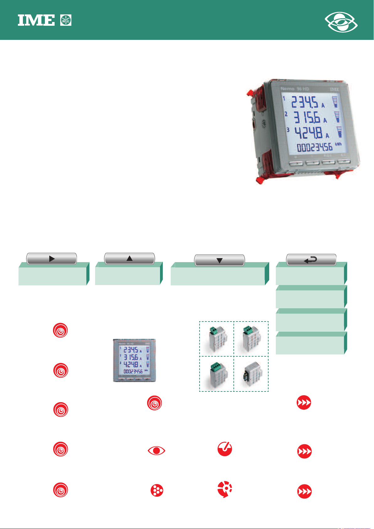
Die Anzeige der Messwerte is auf vier Hauptgruppen unterteilt. Durch Drücken der
entsprechenden Funktionstaste wird die Anzeigegruppe ausgewählt :
U
I PQS ET
DISPLAY
Type of display: LCD backlit
Automatic backlit reduction off after 20 s that keyboard is not used
N° of reading points: 10.000 4 digits (high digit 12 mm)
Energy count: 8 digit counter (high digit 8 mm)
Engineering units: automatic display according to the set VT and CT ratios
Resolution: automatic, with the highest possible number of decimals
Decimal point: automatic, with the highest possible resolution
Reading update: 1,1 seconds
Accuracy (of the reading)
- Voltage: ± 0,2% ± 1 digit (80...500V phase - phase)
- Current: ± 0,2% ± 1 digit (10...120% In)
- Powers: according to EN/IEC 62053-22 and EN/IEC 62053-23
- Frequency: ± 0,15 Hz
Energy count reference value 230(400)V 5A 50Hz
- Active energy: class 0,5s (EN/IEC 62053-22)
- Reactive energy: class 2 (EN/IEC 62053-23)
RUN HOUR METER
Count start: with L1 voltage (>50V)
DISPLAY PAGES
Display is divided into four menus which can be reached with the relevant function
keys:
SPANNUNG
Phasenspannung und verkettete Spannung
VOLTAGE
phase and linked
SPANNUNG (MINIMUM)
je Phase
MINIMUM VOLTAGE
phase
SPANNUNG (MAXIMUM)
je Phase
MAXIMUM VOLTAGE
phase
OBERWELLENGEHALT SPANNUNG
je Phase
VOLTAGE HARMONIC DISTORTION
phase
1
werte gültig ab Firmware-Version 2,15
Auf allen Anzeigeseiten wird immer die Gesamtwirkenergie oder
Gesamtblindenergie (abwechselnd) angezeigt.
Phasenstrom und Neutralleiterstrom
MAX. STROMMITTELWERT
OBERWELLENGEHALT STROM
CURRENT HARMONIC DISTORTION
STROM
CURRENT
phase and neutral
STOMMITTELWERT
je Phase
CURRENT DEMAND
phase
je Phase
MAX. CURRENT DEMAND
phase
SUMMENSTROM
AVERAGE CURRENT
I1 + I2 + I3
3
je Phase
phase
PROGRAMMIERUNG
Programmierung: über die vier Fronttasten
Programmierzugang: geschützt über Passwort
Speicherung der Daten und Konfigurationsparameter: in einem nicht flüchtigen
Speicher (ohne Batterie)
LEISTUNG (GESAMT)
Wirk-, Blind-, Scheinleistung
THREE-PHASE POWER
active, reactive, apparent
LEISTUNG (JE PHASE)
Wirk-, Blind-, Scheinleistung
PHASE POWER
active, reactive, apparent
LEISTUNGSMITTELWERT
Wirk-, Blind-, Scheinleistung
POWER DEMAND
active, reactive, apparent
MAX LEISTUNGSMITTELWERT
Wirk-, Blind-, Scheinleistung
MAX. POWER DEMAND
active, reactive, apparent
1
Values valid starting from 2,15 Firmware version
The total active or reactive energy (alternatively) is always displayed on all the
display pages.
LEISTUNGSFAKTOR
Gesamt und je Phase
POWER FACTOR
phase and three-phase
FREQUENZ
FREQUENCY
BETRIEBSSTUNDENZÄHLER
Betriebsstunden und Minuten
RUN HOUR
working hours and minutes
WIRKENERGIE (POSITIV)
Gesamt- und Teilzähler
POSITIVE ACTIVE ENERGY
partial and total
BLINDENERGIE (POSITIV)
Gesamt- und Teilzähler
POSITIVE REACTIVE ENERGY
partial and total
WIRKENERGIE (NEGATIV)
NEGATIVE ACTIVE ENERGY
BLINDENERGIE (NEGATIV)
NEGATIVE REACTIVE ENERGY
1
1
PROGRAMMING
Parameters programming: front keyboard, 4 keys
Programming access: protected by password
Data and configuration parameters retention: non volatile memory (no battery)
Ausgabe Seite ..2/6
a
NT680 08 - 2010 10
Page 3

PROGRAMMIERBARE PARAMETER
EINGANG
Netzart: Wechselstromnetz und Drehstromnetz 3- und 4-Leiteranschluss
Nennstrom: 1 - 5A
Wandlerübersetzung (Spannung): 1...10 (max. Primärspannung VT1200V)
Wandlerübersetzung (Strom): 1...9999 (max. Primärspannung CT 50kA/5A - 10kA/1A)
STROMMITTELWERT - LEISTUNGSMITTELWERT Primärstrom
Integrationszeit: 5/8/10/1 5/2 0/30/60 min.
DISPLAY
Kontrast: 4 Stufen einstellbar
Hintergrundbeleuchtung: 0 - 30 - 70 - 100%
Einstellbare Anzeigeseite: angezeigte Messgröβen nach dem Einschalten
PROGRAMMABLE PARAMETERS
INPUT
Connection: single-phase and three-phase network, 3 and 4-wire
Current rating: 1 - 5A
External VT ratio: 1...10 (max. VT primary 1200V)
External CT ratio: 1...9999 (max. CT primary 50kA/5A - 10kA/1A)
CURRENT DEMAND - POWER DEMAND
Average period: 5/8/10/15/20/30/60 min.
DISPLAY
Contrast: 4 selectables value
Backlit: 0 - 30 - 70 - 100%
Customized page: content of default page
RÜCKSETZBARE PARAMETER
Min. und Max. Spannung
Strommittelwert
Max. Strommittelwert
Leistungsmittelwert, Wirk-, Blind-, Scheinleistung
Betriebsstunden
Wirkenergie (Teil)
Blindenergie (Teil)
EINGANG
Wechselstromnetz, Drehstromnetz 3- und 4-Leiteranschluss
Spannung (Drehstromnetz) : 80...500V (Phase-Phase)
Spannung (Wechselstromnetz): 50 - 290V
Anschluss nur in Verbindung mit externen zugeordneten Stromwandlern
Nennstrom In: 5A - 1A
Max. Strom Imax: 1,2In
Überlast dauernd: 20 In/0,5 Sekunden
Nennfrequenz fn: 50Hz
Toleranz: 47...63Hz
Messverfahren: True RMS Umsetzung
Oberwellengehalt: gem EN/IEC 62053-21 und EN/IEC 62053-23
Messbeginn (Energiezähler): < 5 Sekunden
Eigenverbrauch (Spannungspfad): ≤ 0,5VA (je Phase)
Eigenverbrauch (Strompfad): ≤ 0,5VA (je Phase)
RESETTABLE PARAMETERS
Min. and max. voltage value
Current demand
Current max. demand
Active, reactive, apparent power max. demand
Run hour
Partial active energy
Partial reactive energy
INPUT
Single-phase network, three-phase network 3 and 4-wire
Three-phase voltage: 80...500V (phase-phase)
Single-phase voltage: 50 - 290V
Connection with external dedicated current transformers
Current rating In: 5A - 1A
Max. current Imax: 1,2In
Instantaneous overload: 20In/0,5 seconds
Frequency rating fn: 50Hz
Tolerance: 47...63Hz
Type of measurement: true RMS value
Harmonic content: according to EN/IEC 62053-22 and EN/IEC 62053-23
Start time (energy count): < 5 seconds
Voltage rated burden:≤0,5VA (each phase)
Current rated burden:≤0,5VA (each phase)
HILFSSPANNUNG
Hilfsspannung Uaux ac: 80...265V
Nennfrequenz: 50Hz
Arbeitsfrequenz: 47…63Hz
Eigenverbrauch: ≤ 4VA (ohne Module)
Hilfsspannung Uaux dc: 110...300Vdc
Eigenverbrauch : ≤ 3,5W (ohne Module)
Verpolungsschutz
ISOLATION (EN/IEC 61010-1)
Installationskategorie: III
Verschmutzungsgrad: 2
Isolationsspannung: 300V (Phase - Neutralleiter)
Stoβspannungsfestigkeit 6kV 1,2/50µs 0,5J
Prüfkreis: Messeingang,Hilfsspannung
Prüfspannung 4kV R.M.S. 50Hz/1min
Prüfkreis: Alle Kreise und Erde
ELEKTROMAGNETISCHE VERTRÄGLICHKEIT
Ausgabe Seite 3/6
a
Emmissiontest und Immunitätstest gem. EN/IEC 62052-11
ARBEITSBEDINGUNGEN
Referenztemperatur: 23°C ± 2°C
Arbeitsbereich: -5...55°C
NT680 08 - 2010 10
Grenztemperatur für Lagerung und Transport: -25...70°C
AUXILIARY SUPPLY
Rated value Uaux ac: 80...265V
Rated frequency: 50Hz
Working frequency: 47…63Hz
Rated burden:≤ 4VA (without modules)
Rated value Uaux dc: 110...300Vdc
Rated burden:≤ 3,5W (without modules)
Protected against incorrect polarity
INSULATION (EN/IEC 61010-1)
Installation category: III
Pollution degree: 2
Insulation voltage rating: 300V (phase - neutral)
Impulse voltage test 6kV 1,2/50µs 0,5J
Considered circuits: measure, aux. supply
A.C. voltage test 4kV r.m.s. value 50Hz/1min
Considered circuits: all circuits and earth
TESTS FOR ELETROMAMAGNETIC COMPATIBILITY
Emission and Immunity tests according to EN/IEC 62052-11
ENVIRONMENTAL CONDITIONS
Reference temperature: 23°C ± 2°C
Specified operating range: -5...55°C
Limit range for storage and transport: - 25...70°C
Page 4
Tropenausführung
A
B
C
D
Max. Verlustleistung1:≤ 5W
1
zur thermischen Dimensionierung des Schaltschrankes
Suitable for tropical climates
Max. power dissipation1: ≤5W
1
For switchboard thermal calculation
GEHÄUSE
Gehäuse: Schalttafeleinbau (Schalttafelausschnitt 92x92mm)
Frontrahmen: 96x96mm
Einbautiefe: 61mm
Max. Einbautiefe: 82mm (mit optionalen Modul)
Anschluss: Schraubanschluss (Stromeingang)
Schraubanschluss mit abnehmbarer Steckerleiste (Spannungseingang)
Anschluss (Spannung):
Draht (starr) max.4,5 mm
Anschluss (Strom):
Draht (starr).6 mm
Gehäusematerial: Polycarbonat, selbstverlöschend
Schutzart (EN/IEC 60529): IP54 (Front), IP20 (Anschlüsse)
Gewicht: 285 Gramm
2 -
Draht (flexibel) max.2,5 mm
2 -
Draht (flexibel) max.4 mm
2
2
OPTIONALE MODULE
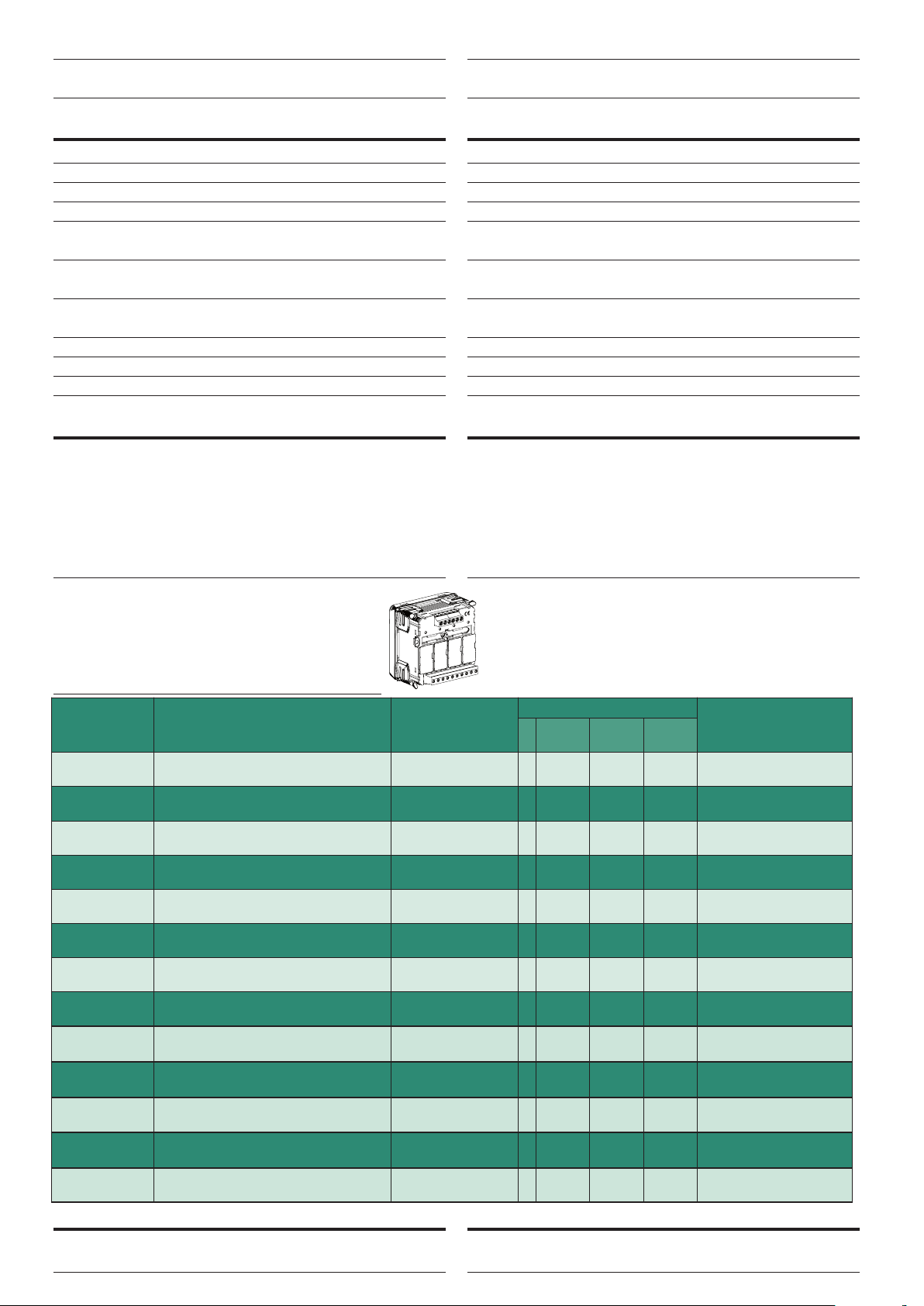
Es können bis zur vier optionale Module im Multifunktionsmessgerät aufgenommen werden.
Maximal zwei Module für Impulsausgang, Analogausgang und Grenzkontakte können in das
Gerät eingesetzt werden.
Aus der nachfolgenden Tabelle kann die maximale Anzahl der Module und deren mögliche
Steckplatzpositionen entnommen werden.
HOUSING
Housing: flush mounting (panel cutout 92x92mm)
Front frame: 96x96mm
Depth: 61mm
Max. depth: 81mm (with optional modules)
Connections: screw terminals (input current)
to plug out (input voltage)
Volmetric terminal range: rigid cable max.4,5 mm
flexble cable max.2,5 mm
Ammetric terminal range: rigid cable max.6 mm
flexble cable max.4 mm
Housing material: self-extinguishing policarbonate
Protection degree (EN/IEC 60529): IP54 front frame, IP20 terminals
Weight: 285 grams
2
2
2
2
OPTIONAL MODULES
In the meter up to four optional modules can be connected.
Communication modules are as an alternative to them (they cannot coexist).
For the options pulse outputs, analog output and alarms, it is possible to connect
one or two modules.
In the table are listed module composition constrictions: max. number of modules
and connection position.
1
FIRMWARE-Version : Die Tabelle gibt an, welche Firmware-Version der
Nemo 96HD/HD+ benötigt, um dieses Erweiterungsmodul zu
unterstützen. Mit Hilfe des Moduls IF96001 (RS485) oder IF96002
(RS232), kann ein Update der Firmware vorgenommen werden. Hierzu
benötigen Sie einen PC und die entsprechende Software.
Bestellnummer
CODE
IF96001
IF96002
IF96003
IF96004
IF96005
IF96006
IF96007
IF96009
IF96010
IF96011
IF96012
IF96013
IF96014
I/O 2 Eingang SPST - 2 Ausang SPST
I/O 2 Eingang 12-24Vdc - 2 Ausang SPST
I/O 2 Inputs 12-24Vcc - 2 Outputs SPST
Beschreibung
DESCRIPTION
Kommunikation RS485
RS485 communication
Kommunikation RS232
RS232 communication
2 Impulsausgang
2 energy pulse output
2 Analogausang 0/4...20mA
2 analogue outputs 0/4...20mA
2 Grenzkontakte
2 alarms
Neutralleiterstrom
Neutral current
Kommunikation PROFIBUS
PROFIBUS communication
Kommunikation LONWORKS
LONWORKS communication
I/O 2 Inputs SPST - 2 Outputs SPST
Speicher - RS485
RS485 - Energy value storage
Kommunikation MBUS
MBUS communication
Kommunikation BACNET
BACNET communication
with the help of a PC and the download software.
max. Anzahl
N. MAX.
1
1
2
2
2
1
1
1
2
2
1
1
1
1
On the table it is shown the Firmware version of the
meter which supports the function of the extra module.
By using an IF96001 (RS485) or IF96002 (RS232)
communication module it is possible to update the
firmware version (starting from 2.00 versiondirectly on field,
Steckplatz POSITION
A B C D
•
•
• • • •
• •
• • • •
•
•
•
• • •
• • •
•
•
•
Firmware
FIRMWARE
Alle
All
Alle
All
Alle
All
1.08
Alle
All
1.08
1.08
2.00
2.06
2.06
2.06
2.06
2.08
1
1
Ausgabe Seite ..4/6
a
KOMMUNIKATION ETHERNET (NT685)
Durch die Verwendung von ein IF96001 (Kommunikation RS485) Modul + IF2E001
(RS485/Ethernet) Kommunikation Schnittstellen
ETHERNET COMMUNICATION (NT685)
By using an IF96001 (RS485 communication) module + IF2E001 (RS485/Ethernet)
communication interface
NT680 08 - 2010 10
Page 5

2
58
1
11
3
6
9
4
7
S1
P
1
aAb
B
L
N
L
OAD
X
2
0
A
UX.
S
UPPLY
2121
+
–
2
1
1
INPUT
VOLTAGE
CURRENT
X
X
X
S1
P1
S1
P1
S1
P1
aAbBaAb
B
L1
L2
L3
LOAD
2
5
8
INPUT
VOLTAGE
CURRENT
20
AUX.
SUPPLY
2121
+
–
2
58 1
3
6
9
4
7
11
ANSCHLUSSBILDER WIRING DIAGRAMS
X
X
X
S1
P1
S1
P1
aAbBaAb
B
L1
L2
L3
LOAD
2
5
8
INPUT
VOLTAGE
CURRENT
20
AUX.
SUPPLY
2121
+
–
2
58 1
3
6
9
4
7
11
X
X
X
S1
P1
a
A
L1
L2
L3
N
X X
X
LOAD
INPUT
VOLTAGE
C
URRENT
20
A
UX.
SUPPLY
2121
+
–
2
58 1
3
6
4
7
11
2
58
11
9
X
X
X
S1
P1
aAbBaAb
B
L1
L2
L3
LOAD
2
5
8
INPUT
VOLTAGE
CURRENT
2
0
A
UX.
S
UPPLY
2121
+
–
2
58 1
3
6
9
4
7
11
1n1E
WECHSELSTROMNETZ
Single phase network
3-1E
DREHSTROMNETZ, 3- LEITER, 1 SYSTEM
Three-phase 3-wire network 1 system
S 1000/265
S 1000/315
S 1000/316
3n1E
DREHSTROMNETZ, 4- LEITER, 1 SYSTEM
Three-phase 4-wire network, 1 system
S 1000/266
3-2E
DREHSTROMNETZ, 3- LEITER, 2 SYSTEM
Three-phase 3-wire network, 2 systems
IME Messgeräte behält sich das Recht vor, die technischen Merkmale ohne Benachrichtigung zu ändern
S 1000/267
3-3E
DREHSTROMNETZ, 3- LEITER, 2 SYSTEM
Three-phase 3-wire network, 3 systems
Ausgabe Seite 5/6
a
NT680 08 - 2010 10
Page 6
X
X
X
S1
P1
S1
P1
S1
P1
a
A
L1
L2
L
3
N
X X
X
L
OAD
INPUT
VOLTAGE
CURRENT
20
A
UX.
SUPPLY
2
121
+
–
2
5
81
3
6
9
4
7
1
1
2
5
8
1
1
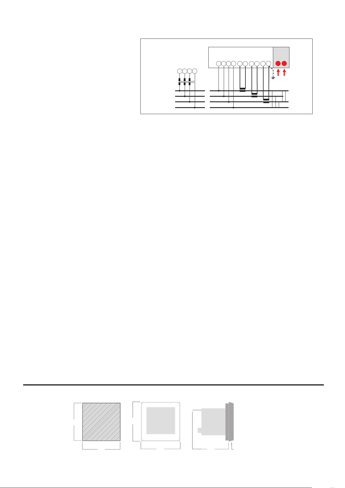
3n3E
92
92
92
12
96
96
DREHSTROMNETZ, 4- LEITER, 3 SYSTEM
Three-phase 4-wire network, 3 Systems
S 1000/268
ABMESSUNGEN DIMENSIONS
Ausgabe Seite 6/6
a
NT680 08 - 2010 10
 Loading...