


VeriLUM® 4.3
Color and Grayscale Video Display Calibration,
Verification and Tracking,
Acceptance Testing
by
IMAGE Smiths, Inc.
19508-C Amaranth Drive, Germantown, MD 20874
Voice / Technical Support: 301-515-7500
Fax: 301-515-8600
Web: www.image-smiths.com
Technical Support : Neil@image-smiths.com
Sales: Chuck@image-smiths.com

This User Guide describes installation and operation of VeriLUM® Version 4.3.
Revision Date: November 1, 2001
Copyright © 1999 by IMAGE Smiths, Inc. All rights reserved.
Copyright permission granted for display of the SMPTE Test Pattern Rev. 10/ 6/83 by the Society of
Motion Picture and Television Engineers and for the CIE 1931 Chromaticity Diagram by Joe Kane
Productions, Inc.
Trademarks, service marks, and other registered names are hereby acknowledged to be the property of
their owners: Adobe Systems, Incorporated; Appian Graphics; Astro Design, Inc.; BARCO, Inc.;
Dicom; DOME Imaging Systems, Inc.; Intel Corporation; Matrox Electronic Systems, LTD; Microsoft
Corporation; National Display Systems; National Electrical Manufacturers Association; NEC; Sequel
Imaging Corporation; and Tektronix, Inc.
Companies and organizations should be contacted for complete information regarding trademarks and
other registrations.
VeriLUM is compliant with year 2000 standards and will not be affected by dates occurring before,
during, or after the year 2000.
2

Table of Contents
Preface
1.0 Getting Started
1.1 System Requirements
1.2 Installing VeriLUM
1.3 Running VeriLUM
1.4 Uninstalling VeriLUM
2.0 Operating VeriLUM
2.1 Using VeriLUM for Acceptance Testing
2.2 Using VeriLUM for Calibration to a Luminance Response Model
2.3 Using VeriLUM for Verification and Tracking
2.4 Color Adjustments
2.5 Plot Results
3.0 Technical Notes
3.1 White Level and Black Level Settings
3.2 Selecting Luminance Measuring Device
3.3 Number of Luminance Measurements
3.4 Data File Format for User Defined Luminance Response Model
3.5 Registry Entries and Downloadable Gamma Ramps
3.6 CIE Chromaticity Coordinates
3.7 Color Temperature
3.8 Using VeriLUM with Multiple Color Monitors on a Desktop
4.0 Calibration Scenarios
4.1 One or More Grayscale Video Displays and BARCO or DOME Video Card
4.2 Windows 95/98/NT/2000 and Color Monitor and Downloadable Gamma Ramp Video
Card
4.3 Windows 95/98/NT/2000 and Color Monitor and Non-Downloadable Gamma Ramp
Video Card
3

Preface
VeriLUM® 4.3 is a tool for ensuring consistent color and grayscale video display performance. In the past
this function has been the province of the video card vendors and the video monitor manufacturers. More
recently the responsibility for assuring the quality of soft copy display has been placed exactly where hard copy
quality assurance resides: in the hands of the end user. This means the end user must be able to make
reproducible measurements of the video display performance and interpret and act on the results.
Our goal is to make it easy and efficient to judge when a video display system is continuing to function
normally or needs adjustment or replacement.
One use of VeriLUM is acceptance testing of a video display system prior to signing off on procurement
paperwork.
VeriLUM also provides a quick visual check for the user. A SMPTE test pattern and a VeriLUM test pattern
can be displayed on each video monitor that is part of the desktop. If the grayscale range and stability is
adequate for each monitor, if the geometry and focus are acceptable, and if all of the monitors have essentially
the same look-and-feel, then the video system is ready for use. If one or more of the video displays is in need of
adjustment then maintenance can be requested.
For the quality assurance specialist interested in tracking consistent performance over time, a rapid set of
measurements of the display luminance is made and an index is computed for each video monitor. These
measurements take about 30 seconds per monitor and the history chart can be printed when hardcopy
documentation is required. The computed index indicates how well the video system matches a specific
luminance response model. Even if the “natural gamma” of the monitor is used, it is still possible to track the
computed index, the white level, and the black level, over time.
In addition, for color monitors, the correlated color temperature and chromaticity coordinates of the white level
and the luminance values for the red, green, and blue primaries are tracked.
VeriLUM also can be used to perform gamma correction in conformance with the DICOM® Part 14
Grayscale Standard Display Function or a user specified gamma model or any other user defined luminance
response model. Loading a lookup table at system startup time is possible if a grayscale video board is used
that has the facility for on-board gamma correction. Currently VeriLUM provides on-board gamma correction
using BARCO, DOME, Appian, and Astro grayscale video boards. If the operating system is Microsoft
Windows 95 or 98 or 2000 and if the color video card supports downloadable gamma ramps then VeriLUM will
use that capability, and download the gamma ramp onto the video card automatically. If the operating system is
Windows NT, then a few video cards support downloadable gamma ramps using non-standard driver calls (e.g.,
Matrox G200/G400/G450 and Appian Jeronimo 2000).
For color monitors two techniques are provided for adjusting the color presentation. If the operating system
and video card support downloadable gamma ramps, then VeriLUM can automatically adjust the red, green,
and blue (RGB) relative gains in order to achieve a user specified color temperature. However, even if
downloadable gamma ramps are not supported, guidance is provided about the appropriate RGB luminance
levels needed in order to achieve a desired luminance level and color temperature.
4

A VeriLUM luminance pod must be connected to the PC each time the software is run. There are two different
VeriLUM pods: color and grayscale. The same software package works with either pod type. A grayscale pod
must be used with grayscale monitors. The grayscale pod can be used on color monitors, but the chomaticity
measurement features will not be available. The color pod provides chromaticity and luminance measurements
on color monitors.
Please note that, unlike most PC software packages, VeriLUM software can be installed on as many
workstations as desired; no additional licenses are required. This allows a VeriLUM pod to be taken from
workstation to workstation to perform measurements. The VeriLUM pod uses a serial communications port on
the PC and thus a simple extension cable from the serial port to the front of the PC minimizes the aggravation of
hunting around behind the PC for the proper connector.
In summary, VeriLUM provides a simple, effective tool for performing calibration, tracking, acceptance testing,
and visual verification of a color or grayscale video display system.
5

1.0 Getting Started
1.1 System Requirements
VeriLUM requires an Intel PC; Microsoft Windows 95, 98, NT 4.0, or 2000 Operating System;
and a video card capable of at least 800 X 600 pixels with a minimum of 256 colors (24 bit or 32
bit true color is highly recommended) or a grayscale video board (BARCO, DOME, Appian, or
Astro). Administrator privileges are required to install VeriLUM software in Windows NT 4.0
and Windows 2000.
1.2 Installing VeriLUM
VeriLUM software is shipped on a CD-ROM. Place it in the CD reader, double-click the CD
drive icon, and double-click the VeriLUM43_Install.exe icon with the left mouse button. The
installation script will verify the minimum system requirements, create the necessary folders and
icons, and install the program files and ancillary files.
The install process uses the Microsoft Installer Technology. If the Installer Engine is not already
on the PC, it will be included in the install process and it may be necessary to restart the PC
during and/or after the install procedure.
This User Guide is included on the CD in both Microsoft Word format and in Adobe Acrobat
PDF format. Please print as many copies as you need. In addition, this User Guide is copied to
the folder in which VeriLUM is installed so it is available on each PC where VeriLUM is used.
1.3 Running VeriLUM
[ Note: With one exception, VeriLUM uses the left mouse button exclusively. Thus all references
to clicking imply left mouse button clicks. The exception is a right mouse click to toggle the
gamma correction on and off in VeriDisplay (see Section 2.2). ]
Connect a VeriLUM pod (color or grayscale) to an active COM port on the PC. Auto-detection
of the COM ports is performed. Click on Start / Programs / VeriLUM and then click on the
VeriLUM icon.
Normally the VeriLUM main dialog box appears as shown in Figure 1
However, the first time VeriLUM is run, a configuration dialog box appears (see Figure 2).
Please specify the number of video monitors comprising the desktop. This ensures that the video
measurements are made in the center of each monitor and not the center of the desktop. Click
the OK button to activate the main dialog box of VeriLUM.
The EXIT button returns control to the desktop.
6

The Configuration dialog box has two buttons in the upper right-hand corner that we use to select
the type of VeriLUM pod being used (Grayscale or Color) and the display device being used.
See Figures 2A and 2B.
The default selections are to set up VeriLUM to run with a grayscale pod and on a CRT.
If you have a National Display Systems Nova Series LCD flat panel display running on a Matrox
G200 MMS video card, then click that button. The other choices are for a National Display
Systems Vector Series LCD flat panel and a NEC 1830 LCD flat panel.
Other flat panel vendors and models will be added in the future.
A percent surround value can also be specified. Once specified, this value is used for all
luminance measurements, in particular all luminance measurements for determining the DICOM
Part 14 gamma correction table. The default value is 20%.
All other buttons are described in Section 2, Operating VeriLUM .
When using VeriLUM with a color monitor and an operating system and video card that permits
downloading gamma ramps, a Task Bar Status Area Icon appears. Resting the mouse pointer on
the icon activates the message “Gamma Correction On Off.” Clicking on the icon initiates a
dialogue to toggle the gamma correction lookup table on the video card between gamma
correction and no gamma correction. This allows a user to choose to view color images without
gamma correction of the gray scale and then to choose to view grayscale images with the gamma
correction turned on.
1.4 Uninstalling VeriLUM
An icon for removing VeriLUM is in the Control Panel under the Add/Remove Programs
function. If you click the VeriLUM item in the program list, you will be asked whether you are
certain you want to remove the VeriLUM application. If you answer YES then all files and icons
created as a part of the install process will be removed. Files created during the operation of the
VeriLUM software will not be removed.
7
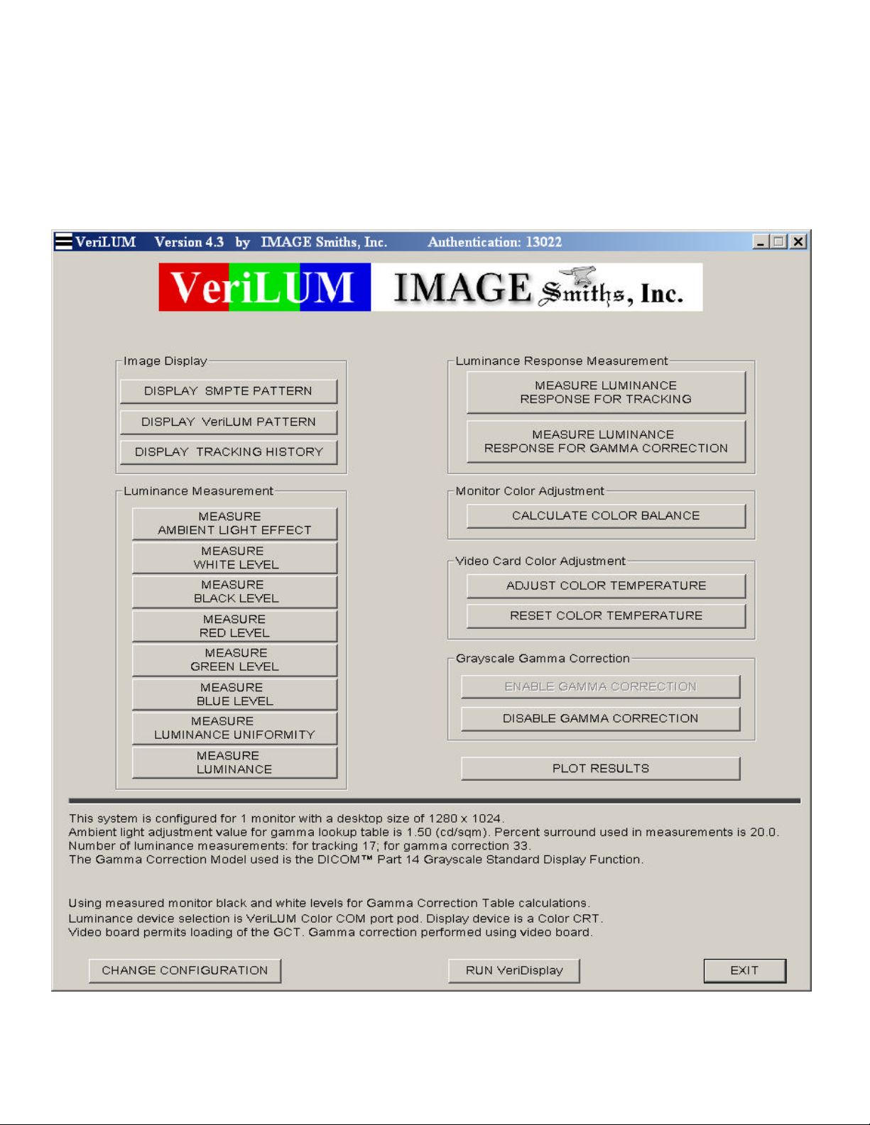
FIGURE 1. VeriLUM Main Dialog Box
8
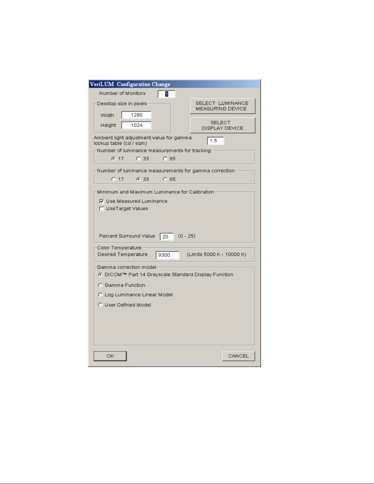
FIGURE 2. VeriLUM Configuration Screen
9
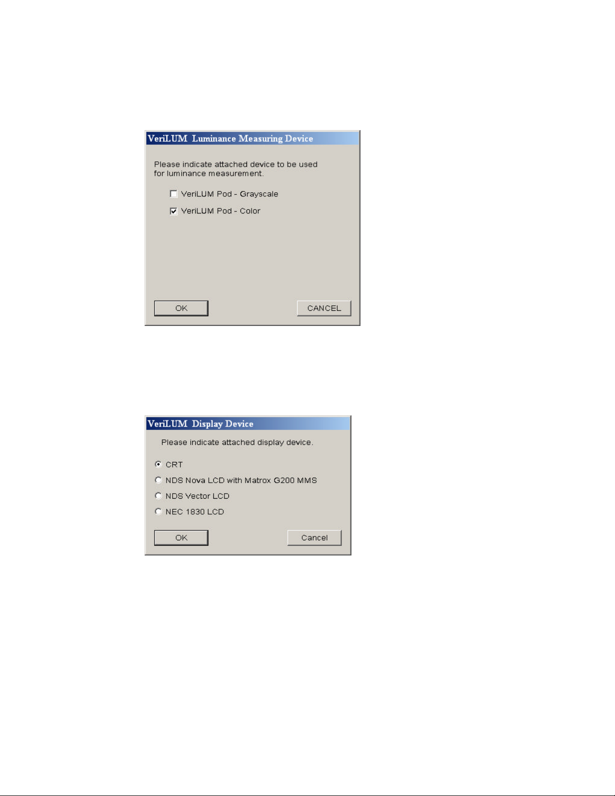
Figure 2A. VeriLUM Luminance Measuring Device Screen
Figure 2B. VeriLUM Display Device Screen
10

2.0 Operating VeriLUM
VeriLUM addresses three major operational requirements for video display quality assurance:
Acceptance Testing; Calibration to a Luminance Response Model; Verification and Tracking.
2.1 Using VeriLUM for Acceptance Testing
2.1.1 DISPLAY SMPTE PATTERN
The SMPTE pattern serves a multitude of purposes. For acceptance testing it is useful to
help determine whether there is video stability and general geometric and luminance
fidelity. Gross distortions such as wavy lines, rectangular areas where square areas are
expected, flicker, smearing and so forth should all be rectified before further testing is
performed. If problems are observed which are not correctable with information supplied
by the video card vendor, video monitor vendor, or system integrator, then a repair call is
warranted.
Click the CONTINUE button to return to the VeriLUM main dialog box.
2.1.2 DISPLAY VeriLUM PATTERN
The VeriLUM pattern also has many uses. For acceptance testing it is used to assess
geometric linearity and focus.
Measure the horizontal and vertical diameters of the large circle centered in the monitor.
Adjust the geometry to equalize these diameters. The diameters of the smaller circles in
the four corners and the center can also be measured to ensure that the circles do not
appear strongly elliptical.
There are five objects used to determine whether the focus is adequate. Each object
consists of four squares and each square has alternating white and black lines in a
horizontal or vertical direction. The focus objects are in the four corners of the monitor
and in the center. Each object should be inspected to determine whether the video
display system is capable of resolving “one on; one off” objects. If the lines are
indistinguishable, or wavy, or smeared, then the focus or astigmatism may need to be
adjusted. This usually requires trained maintenance personnel with specialized
equipment.
Click the CONTINUE button to return to the VeriLUM main dialog box.
2.1.3 MEASURE BLACK LEVEL and MEASURE WHITE LEVEL
These measurements provide an indication of the minimum and maximum luminance at
which the video display system is operating. If a specification for these levels has been
defined by the workstation vendor, then this is a quick way to see whether the video setup
was accomplished. If there are multiple monitors on a workstation and the black and
11

white levels are quite different among the monitors, then it will be very difficult to
display an image on the different monitors and achieve the same look-and-feel. Use these
functions to ensure that the black and white levels are set at about the same value for all
the monitors.
Many monitor vendors provide a digital interface and methodology (software and/or
hardware) for setting the black level and the white level. If the vendor provides
guidelines or if other specifications exist, use them. Otherwise, here are some rules-ofthumb and a suggested procedure.
2.1.3.1 Setting Black Level and White Level Using Brightness and Contrast Controls
2.1.3.1.1 Setting the Black Level and Measuring Ambient Light Effect
Set the room lighting for reading images from the workstation. In
particular, ensure that there are no direct reflections from other objects
in the room (specular reflections from lights, doorways, the desktop,
keyboard, etc.).
Click MEASURE AMBIENT LIGHT EFFECT to get a completely black
screen except for a small gray bar at the bottom of the screen. Using
the monitor brightness control, turn the brightness down and then
slowly raise it until a slight gray appears at the screen edges or across
the whole screen. Then turn the brightness down until the gray goes
away and the screen is uniformly black. Use this as the black level.
To measure the effect of ambient light, hold the VeriLUM pod about
40 cm (16 inches) away from the monitor faceplate with the active
area of the pod parallel to the faceplate. This distance from the
faceplate of the monitor will allow the VeriLUM pod to detect diffuse
reflections from the surface areas directly behind the monitor. Read
the effective luminance in the gray bar at the bottom of the screen and
enter this luminance value into the Configuration Screen item called
Ambient Light Adjustment Value for Gamma Lookup Table.
2.1.3.1.2 Setting the White Level
Click MEASURE WHITE LEVEL button and adjust the monitor contrast
control to give a desired white level. In the absence of vendor
suggestions, try these:
- Color Monitor: 80 cd/sqm (range: 70 to 120)
- High Brightness Monitor: 140 cd/sqm (range: 120 to 180)
- P45 Grayscale Monitor: 250 cd/sqm (range: 200 to 300)
- P104 Grayscale Monitor: 343 cd/sqm (range: 300 to 800)
12

2.1.4 MEASURE LUMINANCE UNIFORMITY
This function measures the white level in the center and four corners of the monitor and
indicates the percentage deviation of the corner luminance value from the center
luminance value. In the absence of some other specification, the percentage deviation
should not exceed plus or minus 15%.
If a VeriLUM color pod is being used, then the correlated color temperature of the white
patches is displayed as well.
2.1.5 MEASURE LUMINANCE
A general luminance measurement function is provided. Place the VeriLUM pod where
you want to measure the luminance. Measurements are made and displayed in one
second intervals. Hit the Space Bar on the Keyboard to capture the luminance reading.
The reading will be written into a date-time-stamped file, and stored in the folder where
VeriLUM was installed.
This is especially useful when VeriLUM is being run on a laptop computer and a
measurement of the luminance of some external self-luminous light source is desired (for
example, a film viewbox).
Click the MEASURE BLACK LEVEL button to display the value in
cd/sqm . In most cases the black level should be between 0.3 cd/sqm
and 1.5 cd/sqm .
If a VeriLUM color pod is being used, other values are displayed in
addition to the luminance. Specifically, the CIE x and y chromaticity
coordinates of the white point are displayed as well as the correlated
color temperature of the white point. See Sections 3.6 and 3.7 for a
discussion of these parameters.
Also, when a VeriLUM color pod is being used, the MEASURE RED
LEVEL, MEASURE GREEN LEVEL, AND MEASURE BLUE LEVEL
buttons are active. These buttons are most useful when manually
adjusting the video display system when the operating system and
video card combination do not permit downloadable gamma ramps.
See Section 4.3 for a calibration scenario in which these buttons are
especially useful.
13

2.2 Using VeriLUM for Calibration to a Luminance Response Model
Click MEASURE LUMINANCE RESPONSE FOR GAMMA CORRECTION button and follow the onscreen instructions for placing the luminance pod and measuring the characteristic luminance
response function of the video display system.
When the measurements are completed a gamma correction table is written to a file in the folder
to which VeriLUM was installed. This gamma correction conforms to the model specified in the
Configuration Screen dialog box. Luminance measurements are written to a file named
LumVals.nc.dat.
The model choices are: DICOM Part 14 Grayscale Standard Display Function; a Gamma Model
with specified gamma value; or a User Defined Model specified by a data file.
Note: See section 3.4 for a description of the data file format for specifying a User Defined
Model.
If the video board has an on-board gamma correction capability then the correction table is
loaded onto the video board after the table is calculated. Currently VeriLUM performs this onboard gamma correction on the grayscale video boards from BARCO, DOME, Appian, or Astro
and the color video cards that support downloadable gamma ramps (for example, Matrox
Millennium and Matrox G200/G400/G450 and Appian Jeronimo 2000).
If the video board does not have an on-board gamma correction capability that is accessible via
the operating system, then no gamma correction table is loaded. The gamma correction file is
available to other software packages to use in writing pixel values to the video display (see
Section 3.5).
In all Windows operating systems (95/98/NT/2000), a gamma correction table is loaded if the
video card supports downloadable gamma ramps.
With gamma correction on-board the effect of perceptual linearization (DICOM® Part 14) can
be seen immediately by clicking DISPLAY SMPTE PATTERN button. You should be able to see
clearly the 5% square in the 0% surround and the 95% square in the 100% surround. The
perceived luminance in the other percentage squares should increase linearly as your eye moves
from the 0% square around to the 100% square in a clockwise direction. Do not be confused by
the optical illusion at the two 50% squares. The luminance appears to be different only because
there is a 40% square to the left of one of the 50% squares and there is a 60% square to the right
of the other 50% square.
You can also click DISPLAY V ERILUM PATTERN button. When DICOM® Part 14 perceptual
linearization has been applied you can see clearly the complete content of this pattern. There are
squares of increasing luminance arrayed left to right across the monitor. There are also smaller
squares within these squares and the pixel values of these smaller squares are obtained by adding
and subtracting from the pixel value of the surrounding square an amount equal to one percent of
the grayscale range.
14

The purpose of the VeriLUM pattern is to see whether a one percent change is visible across the
whole range of pixel values in an image.
When a model other than the DICOM® Part 14 Grayscale Standard Display Function is used, the
features of the VeriLUM and SMPTE patterns that are visualized are model dependent.
If the perceptual linearization effect is not as strong visually as you expected it to be or is too
strong (as judged by the visibility of the 5% square in the 0% surround of the SMPTE pattern),
then click on the CHANGE CONFIGURATION button and enter a different value for the Ambient
Light Adjustment Value. The default value is 1.5 cd/sqm. Increase this value if the workstation
is located in a room with brighter ambient light (adjustment values as high as 20.0 cd/sqm are
sometimes needed). Decrease this value if the workstation is located in a room with very low
ambient light. For flat panel displays, the Ambient Light Adjustment Value should be set to 0.
Click the MEASURE AMBIENT LIGHT EFFECT button to measure the effect rather than
estimating it. Hold the VeriLUM pod away from the monitor faceplate about 40 cm (16 inches)
with the active area of the pod parallel to the monitor faceplate. Luminance readings are
displayed in the gray box at the bottom of the monitor. Enter the value in the Ambient Light
Adjustment Value box on the Configuration Screen. Note that calibration needs to be performed
after a change in the ambient light value for it to take effect.
To see the effect of the calibration, click RUN VeriDisplay button and then click DISPLAY SMPTE
PATTERN button or DISPLAY VeriLUM PATTERN button. Click DISPLAY OTHER PATTERNS
button to see the effect of the gamma correction on your favorite bitmap patterns. Some sample
color and grayscale bitmap images are included in the VeriLUM install folder.
Note: Click the right mouse button on CONTINUE to toggle the gamma correction table on and
off.
In VeriLUM, click ENABLE GAMMA CORRECTION button to have the gamma correction table
loaded then and at system startup and when each user logs onto the system.
Click DISABLE GAMMA CORRECTION button to have a linear ramp loaded into the gamma
correction table then and at system startup. This means that the “natural gamma” of the monitor
will be operable instead of a luminance response model gamma correction.
2.3 Using VeriLUM for Verification and Tracking
Click MEASURE LUMINANCE RESPONSE FOR TRACKING button and follow the on-screen
instructions to perform luminance measurements and compute and display the VeriLUM Display
Index, Effective Ambient Offset, White Level, and Black Level of the video display.
15

A display window presents the current and prior values of these parameters. Click PRINT button
to print the results on the default Windows printer. Click HISTORY PLOT button to display all of
the tracking results since the last calibration. An example is shown in Figure 3. Click JND PLOT
button to display a graph of the JNDs per luminance interval calculated from the tracking
luminance measurements. A judgment is made as to how well the individual values of the JNDs
per luminance interval correlate with theexpected JNDs per luminance interval. A rating of
Excellent, Good, Fair, or Poor is assigned. Click OK button to return to the VeriLUM main
dialog box.
FIGURE 3. Tracking History Plot
16

Figure 3A. JND Conformance Test Results Plot
The VeriLUM Display Index and the Effective Ambient Light parameter have the following
interpretations:
The Display Index is between 01 and 10. The closer the Display Index is to 01 the
closer the video display system is to matching the luminance model specified in the
Configuration Screen.
The Effective Ambient Light indicates the offset that gave the best estimate of the
Display Index.
In all cases the Display Index, Effective Ambient Light, White Level, and Black Level are
tracked over time and significant change in any one of these parameters serves as a warning flag
that something has changed in the video display system and investigation is warranted.
For example, if the Display Index varies by 02 or more index points over time then some
significant change has occurred. Of course the cause may be simply that some user has altered
the brightness or contrast settings for the monitor. Before calling for repair of the monitor a new
17

calibration should be performed, including setting the black level and the white level, and the
SMPTE and VeriLUM patterns should be displayed and visually inspected.
2.4 Color Adjustments
If a VeriLUM color pod is used, then color adjustments can be made in two ways.
If the operating system and video card combination permits downloadable gamma ramps, then an
automatic color adjustment option is available. In the Configuration Screen a Desired Color
Temperature can be specified. The default value is 6500 K that provides good color reproduction
capabilities. See Section 3.7 for a discussion of color temperature and some standard settings.
Click ADJUST COLOR TEMPERATURE and follow the measurement instructions. When the
measurements are completed, relative gain adjustments for red, green, and blue are calculated
and downloaded to the video card downloadable gamma ramps. These gain adjustments are used
to achieve the desired color temperature. The colors achievable by the video card are plotted as
shown in Figures 4 and 5.
18

FIGURE 4. VeriLUM – 1931 CIE Chromaticity Diagram
19
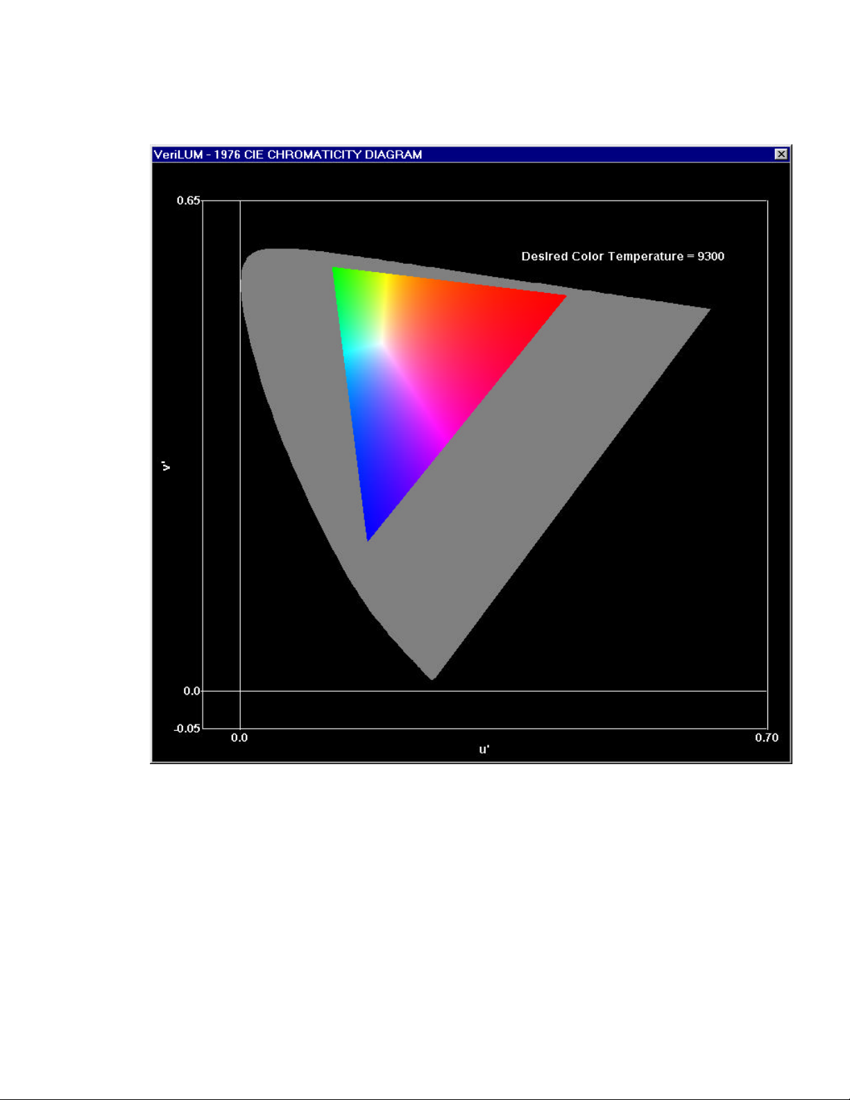
FIGURE 5. VeriLUM – 1976 CIE Chromaticity Diagram
20

To turn off this adjustment click RESET COLOR TEMPERATURE.
An example of this color adjustment scenario is given in Section 4.2.
If the operating system and video card combination does not permit downloadable gamma ramps
(for example, Windows NT 4.0 systems with some color video cards), it still is possible to adjust
the monitor to achieve a desired color temperature. Set the Desired Color Temperature in the
Configuration Screen and then click CALCULATE COLOR BALANCE button.
Given the current white level of the video display, the luminance values for red, green, and blue
are calculated to achieve the desired color temperature of the white level. Click MEASURE RED
LEVEL and adjust the contrast to achieve the suggested luminance value for red. Then click
MEASURE GREEN LEVEL and, using the monitor control for modifying the user color mix, adjust
the percentage for green to achieve the suggested luminance value for green. Then click
MEASURE BLUE LEVEL and use the user color mix monitor control to adjust the percentage of
blue to achieve the suggested luminance value for blue.
This manual procedure will result in a color temperature of the white level which meets the
specified desired color temperature as can be verified by clicking MEASURE WHITE LEVEL.
An example of this color adjustment scenario is given in Section 4.3.
2.5 Plot Results
Click PLOT RESULTS and select one of the plot options as in Figure 6. Examples of these plots
are shown in Figures 7, 8, and 9.
21

FIGURE 6. Select Plot Screen
22

FIGURE 7. Gamma Correction Table Plot
23

FIGURE 8. Calibration Luminance Response Plot
24

FIGURE 9. Tracking Luminance Response Plot
25

3 Technical Notes
3.1 White Level and Black Level Settings
When the MEASURE WHITE LEVEL button is clicked, the highest driving level is used for the
center square and the driving level used for the surround is experimentally determined by
varying the driving levels and taking measurements until the driving level is found that gives a
luminance value of 20% of the maximum luminance. The maximum luminance is the value with
a surround also at the highest driving level.
When the MEASURE BLACK LEVEL button is clicked, a luminance measurement is made in a
square having a zero driving level and a surround with a driving level that gives a luminance that
is 20% of the maximum luminance. It is important to note that the black level in VeriLUM
includes veiling glare from the surround. However, using a VeriLUM pod pressed on the monitor
faceplate occludes the majority of the diffuse ambient light and, therefore, the black level in
VeriLUM does not include the effect of ambient light.
3.2 Selecting Luminance Measuring Device
Click the CHANGE CONFIGURATION button on the VeriLUM main dialog box and then click the
SELECT LUMINANCE MEASURING DEVICE button. Click the check box next to the description
of the device you want to use as the preferred luminance measuring device.
The choices are VeriLUM Grayscale or VeriLUM Color.
The VeriLUM luminance pod is manufactured by Sequel Imaging, Inc., Londonderry, NH, and
has the following characteristics:
Calibration: Traceable to a National Institute of Standards and Technology (NIST) source.
Luminance Accuracy: +/- 4%
Luminance Repeatability: +/- 0.5%
Luminance Range: 0.05 - 450 cd/sqm (color pod); 0.05 – 1500 cd/sqm (grayscale pod)
26

3.3 Number of Luminance Measurements
The CHANGE CONFIGURATION dialog box in VeriLUM permits specification of the number of
luminance measurements for each of tracking and gamma correction.
The choices are 17, 33, and 65.
Cubic spline interpolation is used to produce values for the other driving levels.
3.4 User Defined Luminance Response Model Data File Format
The User Defined Model data file consists of an ASCII text file with the number N of data points
indicated on line 1. The next N lines contain X and Y data values separated by a comma. The X
and Y values are normalized and both are between 0.0 and 1.0. Two sample files are included to
illustrate the format.
The file GAMMA_195.MOD contains 65 data points representing a normalized model for the
luminance response Y = X**1.95. The X value ranges from 0.0 to 1.0 in increments of 1/64.
The Y values are computed at the 65 X values and range from 0.0 to 1.0. The model is used by
multiplying Y by the difference between the maximum and minimum luminance measurements
and then adding the minimum luminance level.
The file EXPONENTIAL_250.MOD contains 65 data points representing a normalized model
for luminance response given by Y = (exp(2.5X) – 1.0) / (exp(2.5) – 1.0).
3.5 Registry Entries and Downloadable Gamma Ramps
When VeruLUM is installed two entries are written to the registry in
HKEY_LOCAL_MACHINE\SOFTWARE\VeriLUM.
The first entry is a key named InstallDirectory and the value of this key is a null-terminated
string containing the fully qualified path name of the folder into which VeriLUM was installed.
Other applications can use this InstallDirectory to determine where the file called GCTn.dat is
located (where n = 0, 1, …, 9 denote monitors on the desktop).
The second registry entry is a key named LoadInd (an abbreviation for load indicator) and the
value of this key is a two character null terminated string. Each of these two characters can
contain the letter N or the letter Y.
The right-most character indicates whether the video card supports downloadable gamma ramps.
The left-most character indicates whether the user of VeriLUM has said to use a gamma
correction or not.
If the LoadInd key has the value YY then a downloadable gamma ramp has been written to the
video board and will be written there whenever the system is restarted. Nothing additional needs
27

to be done by any other application software in order to use the calibration to the desired
luminance response function.
If the LoadInd key has the value NY then the video board is capable of handling downloadable
gamma ramps, but the user of VeriLUM has said “do not use the VeriLUM calibration look-uptable.” Nothing additional needs to be done by other application software.
If the LoadInd key has the value NN, then the video board is not capable of handling
downloadable gamma ramps and the user of VeriLUM has said “do not use the VeriLUM
calibration lookup table.” Nothing additional needs to be done by other application software.
If the LoadInd key has the value YN, then the video board is not capable of handling
downloadable gamma ramps, but the user of VeriLUM wants to use the results of the calibration.
Other application software can then find files named GCTn.dat in the Install Directory for
VeriLUM (n = 0, 1, …, 9). In this case the file contains 256 unsigned short words. This is the
lookup table to be applied to the 256 driving levels of image output data. These words contain
values between 0 and 65535. To obtain the output of the LUT for driving level n, divide the
value of the nth word by 256.
3.6 CIE Chromaticity Coordinates
In 1931 the Commission Internationale de l’Eclairage (CIE) devised a methodology that permits
any color that can be seen by the average human eye to be denoted by a pair <x,y> of real
numbers each of which is between 0 and 1. This pair of numbers is termed the chromaticity of
the color and the graphical representation is called the 1931 CIE Chromaticity Diagram (see
Figure 10 ). In 1976 a modification of this diagram waas promulgated by CIE.
3.7 Color Temperature
A black body radiator is an object which when heated sufficiently produces a light emission
whose color is directly related to the temperature. When the temperature versus the chromaticity
of the emitted color is plotted on the 1931 CIE Chromaticity Diagram, the graph is referred to as
the Planckian locus or black body locus and points on the locus are referred to by their ‘color
temperatures’ (see annotated curve in Figure 10).
Two standard values of color temperature of the white point of a video monitor are important for
medical imaging applications. One is 9300 Kelvin with <x,y> coordinates <0.285, 0.293> and
the other is 6500 Kelvin with <x,y> coordinates of <0.314, 0.3540> .
Many color monitors for the home or office personal computer have been set up to approximate a
9300 Kelvin white point. This white level is decidedly bluish-white. Radiologists often prefer
this representation for grayscale images.
28

The 6500 Kelvin white point is also bluish-white but is more like a daylight fluorescent light.
Colors for pathology specimens often look more realistic and are more reproducible when a
video display system has the white point set at 6500 Kelvin. The initial desired color temperature
in the VeriLUM configuration screen is set to 6500 K.
When a white point is a mixture of colors and has an <x,y> coordinate which does not fall on the
Planckian locus, but is near it, the term ‘correlated color temperature’ is used instead. This is
meant to indicate that the point lies on an iso-temperature line that intersects the Planckian locus
at the indicated color temperature.
Unless a correction can be made to have the white point lie very near to the Planckian locus, one
should be wary of relying on the correlated color temperature. Slight deviations from the locus
can give annoying tints to the image content and yet the white points have the same correlated
color temperature. For example, consider blood on a pathology specimen that has been
photographed with a digital camera and displayed on a video display system. If the blood is red
when the monitor has a white point of 6500 Kelvin on the locus, then a correlated color
temperature of 6500 Kelvin from a white point just slightly above the locus will have a greenish
tint, while a white point just slightly below the locus will impart a purplish tint.The best
objective is to correct to a white point on the Planckian locus. This is what VeriLUM attempts to
do in the ADJUST COLOR TEMPERATURE and CALCULATE COLOR BALANCE functions.
3.8 Using VeriLUM with Multiple Color Monitors on a Desktop
VeriLUM works inconsistently when there are multiple color monitors on a desktop. For
example, when a Matrox G200/G400/G450 video card having a dual-head feature is used, the
downloadable gamma ramp applies only to the first video output (i.e., the left-hand monitor). In
this case, perform the calibration procedure and click the DISABLE GAMMA CORRECTION
button. Then use the technique for applying gamma correction in software instead of using the
downloadable gamma ramps.
The Matrox G200 MMS PCI Quad Display board can be used to correctly calibrate up to four
color monitors driven by a single video card. This works in Windows NT as well as Windows
2000.
In Windows NT with the Appian Jeronimo 2000 dual-head video card, the gamma correction
works correctly on both heads.
29

FIGURE 10. 1931 CIE Chromaticity Diagram
(Courtesy of Joe Kane Productions, Inc.)
30

4 Calibration Scenarios
4.1 One or More Grayscale Video Displays and BARCO, DOME, Appian or Astro Video Card
Step 1. Click CHANGE CONFIGURATION and select the luminance response model to which the
calibration is to conform.
Step 2. Set the black level by following the procedure specified in Section 2.1.3.1.1. Set the
black level on all the monitors at one time.
Step 3. One outcome of the procedure to set the black level is a value to be used for ambient
light adjustment. Enter that value on the configuration screen.
Step 4. Set the white level to the desired luminance. Use the same target value for all the
monitors.
Step 5. If there is some difficulty setting the same black level and the same white level on all
monitors, then take the maximum value of the black levels and the minimum value of the white
levels and enter those values for the minimum luminance and the maximum luminance in the
configuration screen under the option to use target values. Otherwise, choose the option to use
the measured luminance values.
Step 6. Click MEASURE LUMINANCE RESPONSE FOR CALIBRATION to perform the calibration
to the luminance response model you have specified.
Step 7. Click MEASURE LUMINANCE RESPONSE FOR TRACKING to record results as a baseline
for tracking.
4.2 Windows 95/98/NT/2000 and Color Monitor and Downloadable Gamma Ramp Video Card
Step 1. Click CHANGE CONFIGURATION and set the desired color temperature (see Section 3.7
for suggested color temperatures) and select the luminance response model to which the
calibration is to conform.
Step 2. Click the RESET COLOR TEMPERATURE button.
Step 3. Set the black level by following the procedure specified in Section 2.1.3.1.1.
Step 4. Set the white level to the desired luminance (but be sure that the contrast control does
not exceed 90%.)
Step 5. Click ADJUST COLOR TEMPERATURE.
Step 6. Again, use the monitor contrast control to set the white level to the desired luminance.
31

Step 7. Click MEASURE LUMINANCE RESPONSE FOR CALIBRATION to perform the calibration
to the luminance response model you have specified.
Step 8. Click MEASURE LUMINANCE RESPONSE FOR TRACKING to record results as a baseline
for tracking.
4.3 Windows 95/98/NT/2000 and Color Monitor and Non-Downloadable Gamma Ramp Video
Card
Step 1. Click CHANGE CONFIGURATION and set the desired color temperature (see Section 3.7
for suggested color temperatures) and select the luminance response model to which the
calibration is to conform..
Step 2. Set the black level by following the procedure specified in Section 2.1.3.1.1.
Step 3. Use the monitor control to select User Color Mix (sometimes called User Color
Balance) and set each of red, green, and blue to 90%.
Step 4. Set the white level to the desired luminance (but be sure that the contrast control does
not exceed 90%).
Step 5. Click CALCULATE COLOR BALANCE and write down the red, green, and blue
luminance values suggested.
Step 6. Click MEASURE RED LEVEL . Adjust the monitor contrast control to give the desired
red luminance value from Step 5.
Step 7. Click MEASURE GREEN LEVEL. Use the monitor User Color Mix control to increase or
decrease the green percentage to give the desired green luminance value from Step 5.
Step 8. Click MEASURE BLUE LEVEL . Use the monitor User Color Mix control to increase or
decrease the blue percentage to give the desired blue luminance value from Step 5.
Step 9. Click MEASURE LUMINANCE RESPONSE FOR CALIBRATION to perform the calibration
to the luminance response model you have specified.
Step 10. Click MEASURE LUMINANCE RESPONSE FOR TRACKING to record the results as a
baseline for tracking.
32
 Loading...