

Page 1

Setup Manual
Page 2

File: WT36C_WT48C_SetupManual-D2.docx
Page 3

Printed in Germany. All rights reserved.
Reproduction in whole or in part in any form or medium
Ima
Scan2Net
All other trademarks are the property of their respective owners.
Image Access reserves the right to change the
documents at any time without prior notice.
For the most recent version, always check our web site
www.image
2011 – 2015 by Image Access GmbH, Wuppertal, Germany.
ge Access is prohibited.
®
, WideTEK® and Bookeye® are registered trademarks of Image Access.
Setup Manual Page 3
access.us or the customer service portal at portal.imageaccess.de
without express written permission of
described products, the specifications or
www.imageaccess.de or
Page 4

Introduction
Dear Customer,
We congratulate you on the acquisition of this innovative product from Image Access.
We at Image Access are proud of the work we do; it is the result of our extremely high
standards of production and stringent quality control.
With the WideTEK® 36C / WideTEK® 48C, Image Access offers an efficient scanner
which covers a wide scope of applications due to its versatility. Its integrated web-based
user interface makes all functions available in structured menus.
This setup manual is designed to lead you through all setup and administration steps after
the WideTEK
®
36C / WideTEK® 48C scanner has been delivered.
For this reason, we ask you to read this manual attentively before starting to work with the
scanner. By doing so, you will avoid operation errors and you can control all functions
from the beginning.
In addition please consider the following points:
• Damages to your unit may have occurred during shipping. Please check for
damages immediately after delivery of the unit. Inform your supplier if damage has
occurred.
• Read and ensure that you understand the safety notes. They were developed for
your protection and safety as well as to protect the unit.
• Regular maintenance conserves the high quality and safety of the scanner during
the entire service life.
If you have any further questions, please feel free to contact your local dealer or
Image Access directly. Our staff will be happy to help you.
®
For your daily work with the WideTEK
36C / WideTEK® 48C scanner, we wish you
success and complete satisfaction.
Regards
Your Image Access Team
Page 4 Setup Manual
Page 5

About the Manual
Setup Manual
The Setup Manual is written for technical staff with some basic mechanical as well as
software skills. Many resellers will offer onsite installation; therefore, large parts or all of
the setup and assembly manual might not be of interest to the reader. The access level at
which the setup and adjustment processes are performed is called “Power user”. This
“Power user” level is password protected from access by the normal operator.
All manuals can be downloaded from the Image Access customer service portal at
http://portal.imageaccess.de
manuals.
This manual is divided into the sections A to F.
Section A contains the safety notes and the safety precautions. These safety
precautions must be followed carefully to avoid injury to the user while
working with the scanner.
Section B describes the scanner hardware and gives an overview about the scanner’s
components.
. Be sure to always check for the latest versions of these
Section C describes the assembling of the floor stand and optional accessories.
Section D describes the setup and adjustments which can be executed with the
touchscreen.
Section E describes the content and the functions of the Poweruser setup menu. A
wide variety of parameters of the scanner can be set and modified in this
level. It includes information about the firmware update procedure.
Section F shows the technicaldata .
Setup Manual Page 5
Page 6

Version
Published in
Content/Changes/Supplements
Preliminary version.
First release.
Update Technical Data.
Additional information about connectors at the bottom and back
side in chapter 3.x
Copyright note with updated trademark information.
Previous chapter B.5 and all following chapters renumbered.
Copyright note updated.
models are highlighted if necessary.
Copyright note updated.
added, all following chapter renumbered.
Chapter E.4.1.10 Description of document cache settings
added.
Version History
A May 2011
B October 2011
B2 December 2011
B3 January 2012
C March 2013
C1 January 2014
D January 2015
D2 March 2015
Description of the device elements.
Description of assembling steps.
Additional information for menu contents.
Minor modification in technical data.
The new logos for WideTEK® 36C and WideTEK® 48C have
been introduced.
New: Chapter C.4 Mo nitor Moun t.
Technical data updated.
Setup manuals of WideTEK® 36C and WideTEK
scanners merged to one manual. The differences between the
Information about white balance function (chapter D.1.1)
®
48C
Page 6 Setup Manual
Page 7

Table of Content
Introduction ....................................................................................... 4
About the Manual .............................................................................. 5
Version History .................................................................................. 6
A Safety Notes ............................................................................... 14
A.1 Safety Notes.......................................................................................................................14
A.1.1 Marking of Safety Notes ........................................................................................14
A.2 Certification ........................................................................................................................14
A.3 Safety Precautions .............................................................................................................15
A.4 In General ..........................................................................................................................16
A.5 Maintenance.......................................................................................................................16
A.5.1 Touchscreen .........................................................................................................16
A.5.2 Surfaces ................................................................................................................16
A.6 Repair .................................................................................................................................16
A.7 Device Location .................................................................................................................17
B Transport Box ............................................................................ 18
B.1 WideTEK® 36C .................................................................................................................18
B.2 WideTEK® 48C .................................................................................................................20
B.3 Keeping the Transport Box for later use ............................................................................21
B.4 Scanner Dimensions ..........................................................................................................22
B.4.1 WideTEK® 36C ......................................................................................................22
B.4.2 WideTEK® 48C ......................................................................................................23
B.4.3 WideTEK® 36C / WideTEK® 48C with Floor Stand ...............................................23
B.5 Connectors .........................................................................................................................24
B.5.1 Back Side Overview ..............................................................................................24
B.5.2 Connector at the right back side ...........................................................................24
B.5.3 WideTEK® 36C Connectors at the left back side ..................................................25
B.5.4 WideTEK® 48C Connectors at the left back side ..................................................25
C Assembling the Floor Sta nd ...................................................... 26
C.1 Contents of Floor Stand Box ..............................................................................................26
C.1.1 Parts of Floor Stand ..............................................................................................27
C.1.2 Dimensions of Floor Stand Parts ..........................................................................28
C.1.3 List of Assembling Material and Tools ..................................................................29
C.2 Assembling the Floor Stand ...............................................................................................30
Setup Manual Page 7
Page 8

C.3 Securing the scanner at the floor stand ............................................................................ 34
C.4 Monitor Mount ................................................................................................................... 35
C.4.1 Parts of the Monitor Mount ................................................................................... 35
C.4.2 Assembling the Monitor Mount ............................................................................. 36
C.4.2.1 Assembling the Base Plate ................................................................................................ 36
C.4.2.2 Monitor Mount fastening on Base Plate ............................................................................. 37
D Setup and Adjustments ............................................................. 39
D.1 White Balance ................................................................................................................... 40
D.1.1 Information about the White Balance Function .................................................... 40
D.1.2 Performing the White Balance ............................................................................. 41
D.2 IP Address ......................................................................................................................... 42
D.3 User Settings ..................................................................................................................... 43
D.3.1 Change GUI ......................................................................................................... 45
D.3.2 Configure GUI Selection ...................................................................................... 45
D.3.3 Show Application menu ........................................................................................ 46
D.3.4 Set Application as default ..................................................................................... 46
D.4 Time and Date ................................................................................................................... 47
D.5 Testsuite ............................................................................................................................ 48
D.6 User Preset ....................................................................................................................... 49
D.6.1 Preset Selection – Create Pres et ......................................................................... 50
D.6.2 Preset Selection – Configure Preset .................................................................... 51
D.6.2.1 Activating a function in the menus ..................................................................................... 51
D.6.2.2 Saving the preset functions ............................................................................................... 52
D.6.3 Preset Selection – Delete Preset ......................................................................... 53
D.6.4 GUI Selection – Delete GUI ................................................................................. 53
D.6.5 Back to the Kiosk Application ............................................................................... 53
E Poweruser Level ........................................................................ 54
E.1 Setup Menu ....................................................................................................................... 55
E.1.1 Selecting the Login Level ..................................................................................... 55
E.2 Main Menu ........................................................................................................................ 56
E.2.1 Navigating through the menus ............................................................................. 57
E.3 Device Information ............................................................................................................ 58
E.3.1 Device Info ........................................................................................................... 58
E.3.2 Operation Info ....................................................................................................... 58
E.4 Base Settings .................................................................................................................... 59
E.4.1 User Settings ........................................................................................................ 59
E.4.1.1 Language Selection ........................................................................................................... 59
E.4.1.2 File Name .......................................................................................................................... 60
E.4.1.3 Power Saving .................................................................................................................... 61
E.4.1.4 Transport Speed ................................................................................................................ 62
Page 8 Setup Manual
Page 9

E.4.1.5 Volume ............................................................................................................................... 63
E.4.1.6 Start Button Timeout .......................................................................................................... 64
E.4.1.7 Display ............................................................................................................................... 65
E.4.1.8 Splitting Start Page ............................................................................................................ 66
E.4.1.9 Secure File Erasing ............................................................................................................ 67
E.4.1.10 Document Cache ............................................................................................................... 68
E.4.1.11 Kiosk App ........................................................................................................................... 69
E.4.1.12 Show Warnings .................................................................................................................. 70
E.4.1.13 Validate Certificates ........................................................................................................... 70
E.4.2 Network Configuration ...........................................................................................71
E.4.2.1 IP Configuration Method .................................................................................................... 71
E.4.2.2 IPv4 (Network Interface 0) ................................................................................................. 72
E.4.2.3 IPv4 (Network Interface 1) ................................................................................................. 73
E.4.2.4 Domain Name Server ........................................................................................................ 75
E.4.2.5 SMB Settings ..................................................................................................................... 76
E.4.2.6 Firewall............................................................................................................................... 77
E.4.2.7 Wireless LAN (Basic Settings) ........................................................................................... 78
E.4.2.8 Wireless LAN (LAN Interface) ............................................................................................ 79
E.4.2.9 Wireless LAN (Security) ..................................................................................................... 80
E.4.2.10 Wireless LAN (DHCP) ........................................................................................................ 81
E.4.3 Adjust Time & Date ...............................................................................................82
E.4.3.1 Time Format ....................................................................................................................... 83
E.4.3.2 Time Zone .......................................................................................................................... 84
E.4.3.3 Manual Adjustment ............................................................................................................ 85
E.4.3.4 NTP Server ........................................................................................................................ 86
E.4.4 Sound System .......................................................................................................87
E.4.4.1 Set Volume ........................................................................................................................ 87
E.4.4.2 Sound Files ........................................................................................................................ 88
E.4.4.3 Link Events ........................................................................................................................ 89
E.4.5 Installed Options ...................................................................................................90
E.5 Updates & Uploads ............................................................................................................91
E.5.1 Update Scanner Firmware ....................................................................................91
E.5.2 ICC Profiles ...........................................................................................................93
E.5.2.1 Scanner Profile .................................................................................................................. 93
E.5.2.2 Monitor Profiles .................................................................................................................. 95
E.5.2.3 Printer Profiles ................................................................................................................... 97
E.5.3 Touchscreen / Desktop .........................................................................................99
E.5.3.1 Touchscreen ...................................................................................................................... 99
E.5.3.2 Desktop ............................................................................................................................ 100
E.5.4 Java Apps............................................................................................................101
E.5.5 PDF Cover Sheet ................................................................................................102
E.6 Adjustments & Support ....................................................................................................103
E.6.1 Adjustments ........................................................................................................103
E.6.1.1 White Balance .................................................................................................................. 104
E.6.1.2 Brightness Correction ...................................................................................................... 105
E.6.2 Log Files ..............................................................................................................108
E.6.2.1 Show Log Files ................................................................................................................ 108
Setup Manual Page 9
Page 10

E.6.2.2 Stitching Log enabled ...................................................................................................... 109
E.6.3 Network Analyzer ............................................................................................... 110
E.6.3.1 Perform Speed Test ........................................................................................................ 111
E.6.3.2 Packet Statistics .............................................................................................................. 112
E.7 Administrative Settings.................................................................................................... 113
E.7.1 Wake up Remote Host ....................................................................................... 113
E.7.2 Change Password .............................................................................................. 114
E.7.3 Backup Settings ................................................................................................. 115
E.7.4 Restore Settings ................................................................................................. 116
E.7.5 Lock Web App .................................................................................................... 117
E.7.6 Unlock Web App ................................................................................................. 117
E.8 Resets & Default Values ................................................................................................. 118
E.8.1 Set Scanner Defaults ......................................................................................... 118
E.8.2 Reset Factory Defaults ....................................................................................... 118
E.8.3 Reset Scanner Defaults ..................................................................................... 118
E.8.4 Reset Surface ..................................................................................................... 118
E.8.5 Reset Hardware Defaults ................................................................................... 118
E.8.6 Set Default Passwords ....................................................................................... 118
F Technic a l Data WideTEK® 36C / 48C ...................................... 119
F.1 Scanner Specifications.................................................................................................... 119
F.2 Electrical Specifications .................................................................................................. 120
F.3 Ambient Conditions ......................................................................................................... 121
F.4 Dimensions and Weight .................................................................................................. 121
F.4.1 WideTEK® 36C ................................................................................................. 121
F.4.2 WideTEK® 48C ................................................................................................. 121
Page 10 Setup Manual
Page 11

Table of Pictures
Picture 1: Minimum distances 17
Picture 2: WideTEK 36C in transport box 18
Picture 3: Parts in the transport box 19
Picture 4: Wooden frame remove 19
Picture 5: WideTEK 48C and accessories in transport box 20
Picture 6: Transport box elements ready to store 21
Picture 7: WideTEK 36C front view 22
Picture 8: Depth and height of the scanner 22
Picture 9: WideTEK 48C front view 23
Picture 10: Scanner in combination with floor stand and monitor 23
Picture 11: Back of WideTEK 36C 24
Picture 12: Recovery Key connector, covered with plastic cap 24
Picture 13: Left, back side of the scanner 25
Picture 14: Main power switch and connectors 25
Picture 15: Floor stand box opened 26
Picture 16: Assembling material 26
Picture 17: Parts of floor stand 27
Picture 18: Assembly steps 30
Picture 19: Lower crossbeam combined with foot and vertical leg 30
Picture 20: Drawing “Detail C” 31
Picture 21: Inserting screws with washer 31
Picture 22: Bottom and side components assembled 31
Picture 23: Upper longitudinal foot on vertical leg 32
Picture 24: Upper crossbeam inserted 32
Picture 25: Inserting the rod 33
Picture 26: Floor stand complete 33
Picture 27: Parts of monitor mount 35
Picture 28: Base plate with marking „TOP“ 35
Picture 29: Assembling the base plate to the vertical leg 36
Picture 30: Base plate fastened with hexagon head screws 36
Picture 31: First step monitor mount on base plate 37
Picture 32: Final position of monitor mount at base plate 37
Picture 33: Fixing the monitor mount 38
Picture 34: Floor stand with monitor mount 38
Picture 35: Viewer & Job Control screen 39
Picture 36: Setup menu items 39
Picture 37: Setup menu, start screen 41
Picture 38: IP Address mask 42
Picture 39: User Settings menu 43
Picture 40: Selectable presets 45
Setup Manual Page 11
Page 12

Table of Pictures, part 2
Picture 41: Presets selection screen 45
Picture 42: Time and date 47
Picture 43: Testsuite screen 48
Picture 44: User preset screen 49
Picture 45: Keyboard on the touchscreen 50
Picture 46: Selecting the preset content 51
Picture 47: Scan2Net Start Screen 54
Picture 48: Login level screen 55
Picture 49: Main menu Poweruser level 56
Picture 50: Device Info 58
Picture 51: Operation Info 58
Picture 52: Language selector 59
Picture 53: File name 60
Picture 54: List of wildcard characters 60
Picture 55: Power Saving 61
Picture 56: Transport speeds 62
Picture 57: Volume level 63
Picture 58: Start Button timeout 64
Picture 59: Display parameters 65
Picture 60: Splitting start page 66
Picture 61: List of erasing methods 67
Picture 62: Document cache selector 68
Picture 63: Kiosk App selection 69
Picture 64: Show Warnings selector 70
Picture 65: Validate Certificates selector 70
Picture 66: IP Configuration Method 71
Picture 67: Settings of IPv4 (Network Interface 0) 72
Picture 68: Settings of IPv4 (Network Interface 1) 73
Picture 69: Domain Name Server parameters 75
Picture 70: SMB Settings 76
Picture 71: Firewall settings 77
Picture 72: Wireless LAN Basic Settings 78
Picture 73: Wireless LAN (LAN Interface) 79
Picture 74: Wireless LAN (Security) 80
Picture 75: Wireless LAN (DHCP) 81
Picture 76: Time Format 83
Picture 77: Time Zone screen 84
Picture 78: Manual Adjustment 85
Picture 79: NTP Server setting 86
Picture 80: Set Volume 87
Page 12 Setup Manual
Page 13

Table of Pictures, part 3
Picture 81: Sound Files list 88
Picture 82: Upload new sound files 88
Picture 83: Link Events list 89
Picture 84: Options List 90
Picture 85: Update Scanner Firmware 91
Picture 86: Scanner Profile 93
Picture 87: ICC Profile installed 94
Picture 88: ICC Profile inf ormation 94
Picture 89: Monitor Profiles 95
Picture 90: ICC Profile inf ormation 96
Picture 91: Touchscreen menu, ICC profile selected 96
Picture 92: Printer Profiles 97
Picture 93: Touchscreen screensaver 99
Picture 94: Desktop screensaver list 100
Picture 95: Preview of desktop image 100
Picture 96: Java Apps 101
Picture 97: PDF Cover Sheet 102
Picture 98: Adjustment main screen 103
Picture 99: White Reference Target on document table 104
Picture 100: Brightness Correction factor list 105
Picture 101: Stitching start screen 106
Picture 102: Display after measurement 106
Picture 103: Log files overview, software version 6.x 108
Picture 104: Selection box at the bottom of the screen 109
Picture 105: Items of Network Analyzer menu 110
Picture 106: Network Analyzing Parameters 111
Picture 107: Measured Time 112
Picture 108: Packet Statistics values 112
Picture 109: Wake up Remote Host 113
Picture 110: Change password menu 114
Picture 111: Small window at bottom line with inquiry for action 115
Picture 112: Restore setting from ZIP file 116
Picture 113: Message after restoring 116
Picture 114: Enter password to lock the Scan2Net user interface 117
Setup Manual Page 13
Page 14

A Safety Notes
A.1 Safety Notes
Read and ensure that you understand the safety notes.
The safety notes have been written to ensure your protection and for your safety.
Follow all safety notes to avoid damage to the device.
A.1.1 Marking of Safet y Notes
All safety notes are marked with a warning sign.
A description of the potential hazard is found at the right side beside the warning sign.
WARNING!
<Text with description of potential hazard.>
A.2 Certification
Both scanners, the WideTEK® 36C as well as WideTEK® 48C, fulfill the requirements of
the following standards:
IEC 60950-1, International Safety Standard for Information Technology Equipment
UL 60950-1, Safety for Information Technology Equipment (US standard)
CAN/CSA C22.2 No.60950-1, Safety for Information Technology Equipment
(Standard of Canada)
EN 60950-1, Safety for Information Technology Equipment (European standard)
All approval marks for the certifications noted above can be f ound on the type label of the
device.
Page 14 Setup Manual
Page 15

this device to rain
A.3 Safety Precautions
Warning: Please read all the safety precautions before you operat e the scanner. Serious
injury can occur to you or to others if you do not know how to use it safely.
To prevent fire or shock hazard, do not expose
or any type of moisture.
Follow all safety precautions to avoid personal injury or damage to the device.
1. Openings in the scanner’s housing are provided for air circulation. Do not cover or
block the openings.
2. Do not place the scanner near a heat or cold emit ting sourc e such as a space heater,
furnace, or air conditioning unit.
3. Do not place the scanner near any devices or electrical boxes emitting high voltage.
4. Always place the scanner on a stable surface.
5. Do not place cups containing liquids or other such objects on the scanner or on the
book cradles. If liquid spills into the scanner it can cause damage. If this occurs, t urn
off the scanner immediately and unplug the external power supply fr om the scanner.
Contact the Image Access Technical Support.
6. Do not put any objects into any scanner housing openings unless specifically
instructed to do so by Image Access Technical Support.
7. Do not disassemble the scanner. If there is a need to disassemble the scanner,
please contact the Image Access Technical Support.
8. Do not use the scanner if it has been physically damaged. If this occurs, turn off the
scanner and unplug the external power supply from the scanner. Contact the
Image Access Technical Support.
9. The scanner should be used only with the power supply that is delivered with the
scanner. If you are unsure, please contact the Image Access Technical Support.
10. Before cleaning the scanner always turn off the scanner and unplug the external
power supply.
11. When cleaning, do not use any type of solutions, abrasives, or acids such as acetone,
benzene, kerosene, mineral spirits, ammonia, or nitric acid. Do not use any cleaners
that contain these chemicals.
12. Do not spray any liquids directly onto the scanner . Spray cleaning fluids directly onto
the cleaning cloth and use the cloth to clean the scanner.
13. Image Access recommends using f or all cleaning purposes a damp cloth from a soft
lint-free material. Microfiber cloths are very suitable.
Contact the Image Access Technical Support at support@imageaccess.de
Setup Manual Page 15
Page 16

A.4 In General
This setup manual describes both scanner versions, the WideTEK® 36C as well as the
WideTEK
This setup manual describes the settings and functions using a device equipped with all
options. Deviations to other devices with other equipment or reduced options are possible.
®
48C.
A.5 Maintenance
Important: While cleaning the scanner, ensure that no liquids flow into the device
housing.
A.5.1 Touchscreen
The touchscreen can be cleaned with a dry microfiber cloth. Before cleaning, putting the
scanner in standby mode is recommended.
A.5.2 Surfaces
Use a soft, dampened cloth to clean the housing of the scanner. A microfiber cloth is
recommended.
A.6 Repair
Note: No parts or components of the scanner can be repaired by the user.
All repairs should be done by a trained technician.
Page 16 Setup Manual
Page 17
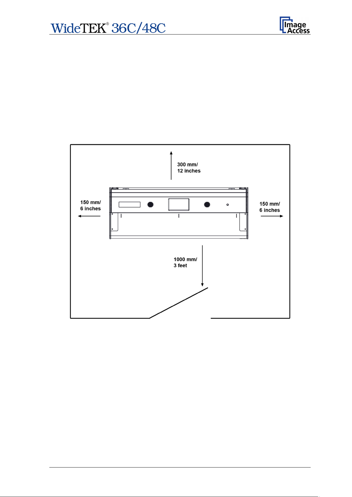
A.7 Device Location
Note: Picture 1 shows a sketch with a WideTEK® 36C. The minimum distances
®
around the scanner are also valid for the WideTEK
48C.
Please allow a minimum of
— 150 mm (6 inch) from any side walls
— 300 mm (12 inch) from a back wall.
— one meter (3 feet) minimum distance from any door or entrance way.
Use the illustration below as a guide.
Picture 1: Minimum distances
Do not operate the scanner in an area that has poor air circulation and/or that is not
ventilated.
Place the scanner on a flat and solid base. The load bearing capacity of the base must
correspond to the device weight.
Choose a location that complies with the temperature and humidity limits. For more
information refer to the chapter F.3.
Important: Before using the scanner in the new environment, allow at least one hour for
temperature adaptation.
Temperature adaptation means:
A fast change from cold to warm environmental conditions can build up
condensation inside the housing. This will result in unfavorable scanned
images and could cause permanent damage to the unit.
Setup Manual Page 17
Page 18

WideTEK® 36C
B Transport Box
In general:
Keep the transport box for later use.
The transport box and the foam inserts will ensure a good protection of the scanner and
all accessories if a transport of the scanner is necessary.
The next chapters give an overview of the content included in the transport box when the
scanner is delivered.
B.1
After removing the top cover of the transport box the paper output tray is visible.
1. Paper Output Tray
The WideTEK
transport box with a total of six foam inserts.
Picture 2: WideTEK 36C in transport box
®
36C scanner as well as the cardboard box of the floor stand is held in the
Page 18 Setup Manual
Page 19
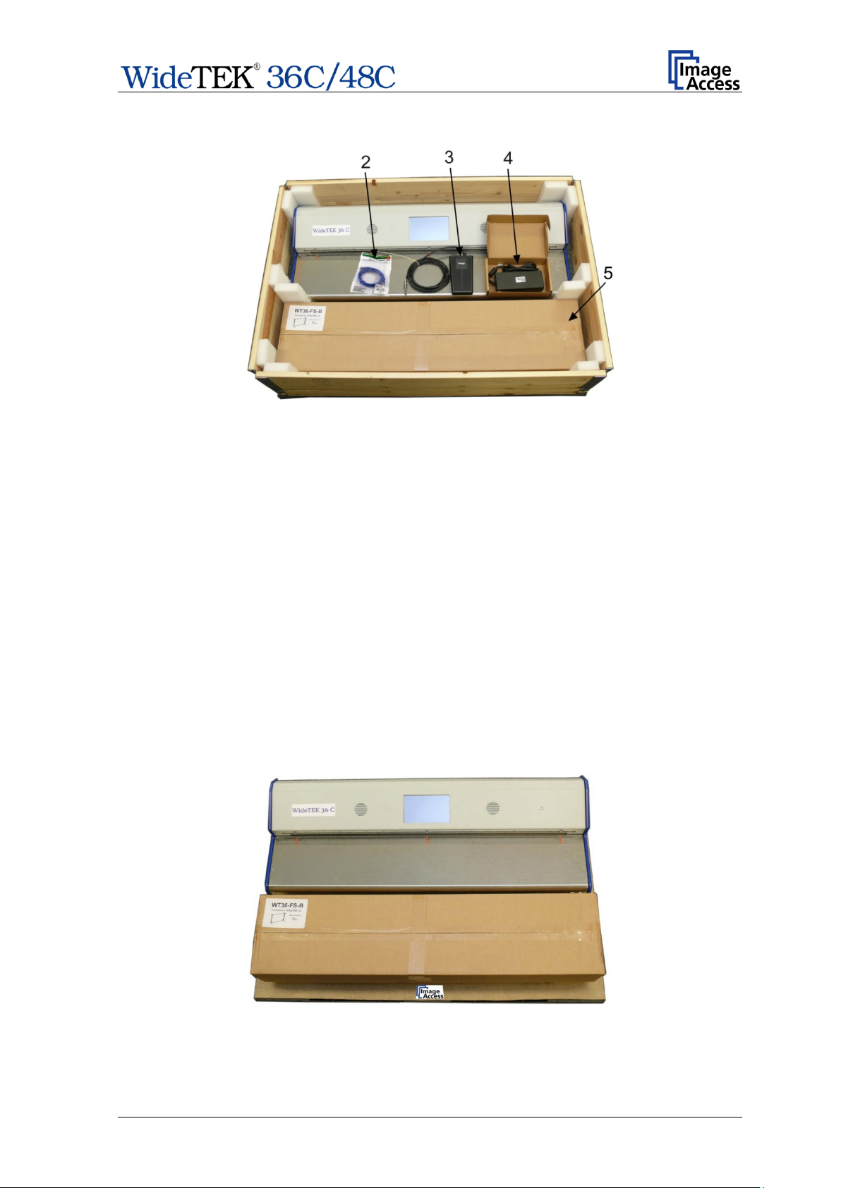
P1060755_
Remove the paper output tray and the foam mat to get access to the next parts.
Picture 3: Parts in the transport box
2. Patch cable
3. Foot pedal switch
c.jpg
4. External power supply with power connector cable
5. Floor stand in cardboard box
Also contained (but not visible at the picture):
− Reference folder with IT8- and CSTT test targets
− O per ation Manual / Setup Manual
− Two plastic bags with Document Return and installation instructions
− White Reference Target
Take the parts out of the transport box.
Remove the six foam inserts beside the scanner and the cardboard box.
Lift the wooden frame from the palett.
Picture 4: Wooden frame remove
The scanner and the floor stand cardboard box can now be lifted from the pallet.
Setup Manual Page 19
Page 20
WideTEK® 48C
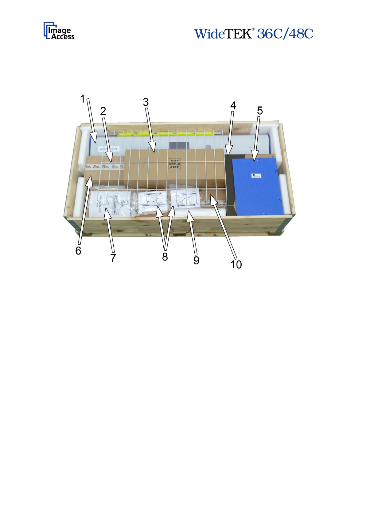
B.2
After removing the top cover of the transport box the scanner and all accessory parts are
visible.
Picture 5: WideTEK 48C and accessories in transport box
The transport box contains
1. Scanner
2. Paper catch basket
3. Monitor mount (optional)
4. External LCD Monitor (optional)
5. Reference folder with IT8 sheet and CSTT test targets
6. Accessory box with
− Power supply
− Power cable for power supply (with national specification)
− Net work cable
− Foot pedal
7. Manuals (Operation manual / Setup manual)
8. 2x bags with Document Returns and installation manual
9. White Reference Target WT48-WA-01-A
10. Floor s t and (optional)
Page 20 Setup Manual
Page 21

B.3 Keeping the Transport Box for later use
All elements used with the transport box can easily be stored.
The wooden frame can be folded. Most of the foam inserts can be placed between the
base plate and the cover plate.
Picture 6: Transport box elements ready to store
The wooden frame can be place on top of the cover plate.
Setup Manual Page 21
Page 22
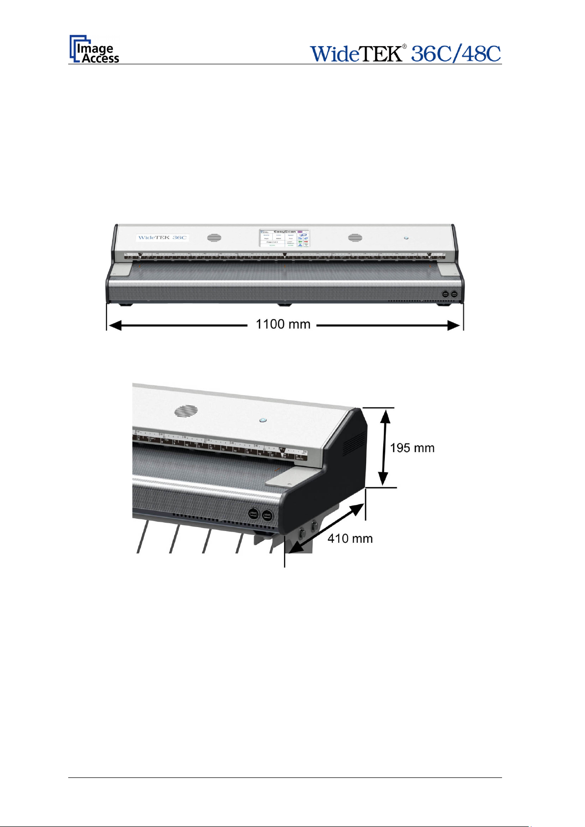
B.4 Scanner Dimensions
The WideTEK® 36C as well as the WideTEK® 48C scanner requires just a small
footprint.
The following pictures show the dimensions of the scanner and give an impression of the
slim scanner housing.
B.4.1 WideTEK® 36C
Picture 7: WideTEK 36C front view
Picture 8: Depth and height of the scanner
Page 22 Setup Manual
Page 23

B.4.2 WideTEK® 48C
Picture 9: WideTEK 48C front view
The depth and the height of the housing are identical with the WideTEK® 36C scanner.
B.4.3 WideTEK® 36C / WideTEK® 48C with Floor Stand
If the scanner is mounted at the recommended floor stand, the resulting height of the
complete system is 1045 mm (41.2 inch).
The combination of floor stand, paper catch basket and the document returns at the back
side of the scanner makes scanning and the document handling easy and comfortable.
Picture 10: Scanner in combination with floor stand and monitor
Setup Manual Page 23
Page 24

B.5 Connectors
Please note: The definition of “left” and “right” are seen from the back side of the
scanner.
B.5.1 Back Side Overview
Both scanner models are equipped with the main switch at the back side and with
connectors for:
• External power supply
• Network cable
• Video signal
• Foot pedal switch
• Recovery key
Differences only exist at the left side in position and type of the video connector.
Picture 11: Back of WideTEK 36C
Note: Picture 11 shows an earlier version of the WideTEK® 36C back side.
B.5.2 Connector at the right back side
Picture 12: Recovery Key connector, covered with plastic cap
On the scanner's right back side find the Recovery key connector.
To protect the sensible pins of the connector, it is covered with a cap.
Remove the cap before connecting the Recovery key to the scanner.
Note: The recovery function should only be activated by an administrator!
Cover the connector again after removing the Recovery key.
Page 24 Setup Manual
Page 25
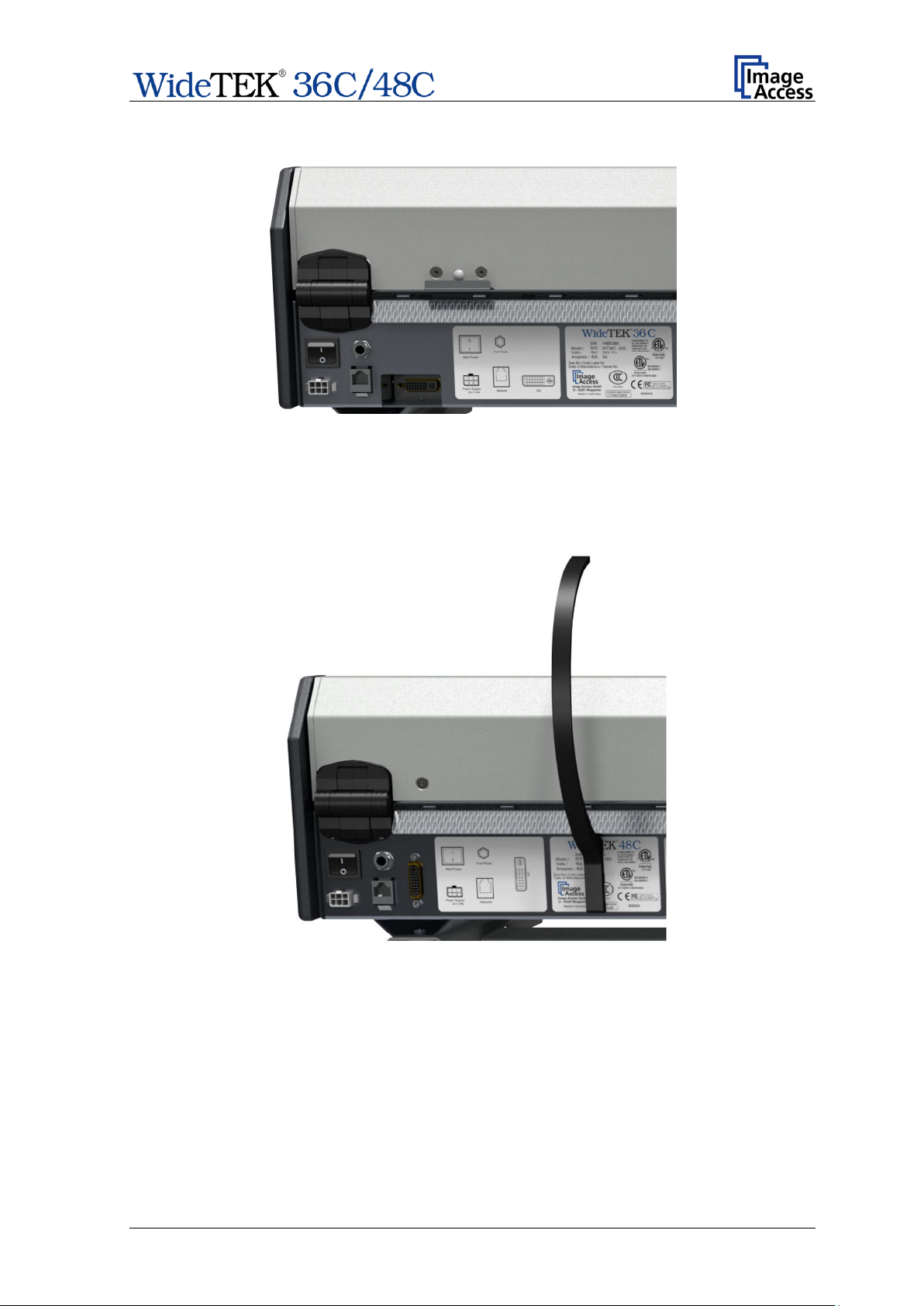
B.5.3 WideTEK® 36C Connectors at the left back side
Picture 13: Left, back side of the scanner
For easy orientation, a label beside the connectors shows and names each connector.
B.5.4 WideTEK® 48C Connectors at the left back side
Picture 14: Main power switch and connectors
For easy orientation, a label beside the connectors shows and names each connector.
Setup Manual Page 25
Page 26

C Assembling the Floor Stand
C.1 Contents of Floor Stand Box
The cardboard box of the floor stand contains a plastic bag with all screws, washers, and
tools required to assemble the floor stand.
Picture 15: Floor stand box opened
1: Plastic bag with assembly material
Picture 16: Assembling material
Page 26 Setup Manual
Page 27

C.1.1 Parts of Floor Stand
The graph below shows and numbered all parts of the floor stand.
Picture 17: Parts of floor stand
Details in the drawing are marked by capital letters and a red circle. The red circle in the
drawing marks the thread nuts
# Amount Description
1 2 Crossbeam
2 1 Vertical leg without threaded bushes
3 2 Crossbeam foot
4 1 Vertical leg with threaded bushes
5 4 Adjustable foot. Pre-mounted at item #3.
6 2 Upper longitudinal foot
7 8 Screw ISO 4014 – M8x50x22
8 8 Washer DIN 9021 – 8.4 (8x)
9 1 Rod 8x982 mm (WideTEK® 36C)/ 8x1287 mm (WideTEK® 48C)
10 4 Hexagon nut. Pre-mounted at item #3.
Setup Manual Page 27
Page 28

the WideTEK 36C / 48C
C.1.2 Dimensions of Floor Stand Parts
Most parts of the floor stand are identical.
Because of mechanical dimensions of the scanners, the floor stands differ in a few details.
Length of crossbeam:
WideTEK
WideTEK
Length of upper longitudinal foot:
WideTEK
Height of vertical leg:
WideTEK
®
36C: 966 mm
®
48C : 1271 mm
®
36C / WideTEK® 48C: 320 mm
®
36C / WideTEK® 48C: 830 mm
The upper longitudinal feet for
floor stand have a bore hole at each end with a diameter
of 24 millimeter.
Page 28 Setup Manual
Page 29

A 8x screws ISO 4014 – M8x50x22
B Combination wrench, size 13
C.1.3 List of Assembling Material and Tools
8x washer DIN 9021 – 8.4
Setup Manual Page 29
Page 30

Step A: Insert a vertical leg (#2 or #4)
into a crossbeam foot (#3). Each
The crossbeam feet are designed
: Insert the lower crossbeam
C.2 Assembling the Floor Stand
Start with a crossbeam (component #1), a vertical leg (component #2 or #4), and a
crossbeam foot (component #3).
Note: The three holes on the vertical legs (component #2 or #4) must be placed
− at the side where the crossbeam will be mounted,
− in the upper part of the vertical leg.
The drawing in Picture 17 illustrates the correct position.
The two holes with threaded bushes of component #4 (marked with red circle) will be used
to hold the monitor mount. They must be positioned at the outside.
crossbeam foot has a cutout for the
vertical leg.
Picture 18: Assembly steps
Picture 19 shows the result of step A and step B.
symmetrically, therefore they fit on the
left and the right side.
Step B
(#1) in the combination of vertical leg
and crossbeam foot.
Picture 19: Lower crossbeam combined with foot and vertical leg
Page 30 Setup Manual
Page 31

Fasten the three components with two screws ISO 4014 – M8x50x22.
The drawing “Detail C” shows, how the screw (item #7) and washer (item #8) must be
combined.
Picture 20: Drawing “Detail C” Picture 21: Inserting screws with washer
Tighten the screws with the combination wrench, size 13, which comes with the floor
stand.
Note: All screws should only be hand-tightened at first. The components should be a
little movable against each other until all parts are assembled.
Repeat the steps described above with the second crossbeam foot and the second
vertical leg.
Picture 22 shows the floor stand after the previously described assembly steps.
Picture 22: Bottom and side components assembled
Setup Manual Page 31
Page 32

Place the upper longitudinal feet (item #6) at the vertical leg s. The oval cut-out must face
to the inner side.
Picture 23: Upper longitudinal foot on vertical leg
Insert the second crossbeam between the vertical legs.
Picture 24: Upper crossbeam inserted
Assemble the upper crossbeam, the upper longitudinal feet and the vertical legs at b oth
sides with two ISO 4016 – M8x50x22-WS screws and washers at each screw.
Tighten the screws with the combination wrench, size 13.
Page 32 Setup Manual
Page 33

Tighten all eight screws with the combination wrench, size 13
Finally, insert the rod between the vertical legs. This rod supports t he paper output tray. It
has three positions for adjusting the height of the paper output tray.
Picture 25: Inserting the rod
The floor stand is complete now.
Picture 26: Floor stand complete
Picture 26 shows the floor stand with the inserted rod. The threaded bushes (red circle)
are positioned to the outside.
Setup Manual Page 33
Page 34

C.3 Securing the scanner at the floor stand
The upper longitudinal feet of the floor stand have a bore hole at each end. The position of
the bore holes correspond with the distance of the rubber feet at the bottom side of the
scanner.
Place the scanner at the floor stand with the rubber feet into the bore holes.
No additional screws which have to be inserted. The scanner is securely held by its own
weight.
Page 34 Setup Manual
Page 35

C.4 Monitor Mount
A monitor mount is available with the floor stand for the WideTEK scanners.
The monitor mount is delivered with all necessary tools and mounting material in a plastic
bag. A separate list shows the content of the plastic bag.
C.4.1 Parts of the Monitor Mount
Picture 27: Parts of monitor mount
The components used to assemble the monitor mount to the floor stand are:
1: 2x Hexagon head screws; M8 x 16, with washer
2: Base plate
3: Allen wrench 2.5 mm
4: Monitor mount
Picture 28: Base plate with marking „TOP“
The arrows in Picture 28 show the holes where the screws must be inserted.
Setup Manual Page 35
Page 36

C.4.2 Assembling the Monitor Mount
C.4.2.1 Assembling the Base Plate
Tool: Combination wrench, size 13
One of the vertical legs has two threaded bushes. When assembling the floor stand, these
two threaded bushes must be positioned outside of the vertical leg. In Picture 17,
component #4 shows the position marked with a red circle.
Use two hexagon head screws to fasten the base plate at the vertical leg.
Picture 29: Assembling the base plate to the vertical leg
Assemble the base plate with the hexagon head screws and the washers which come with
the Monitor Mount.
Picture 30: Base plate fastened with hexagon head screws
Fasten the screws with the combination wrench.
Page 36 Setup Manual
Page 37

C.4.2.2 Monitor Mount fastening on Base Plate
Slide the monitor mount at first on the upper side of the base plate.
Picture 31: First step monitor mount on base plate
Then slide the lower side of the monitor mount over the base plate.
Picture 32: Final position of monitor mount at base plate
Setup Manual Page 37
Page 38

Finally fix the monitor mount with two Allen head screws. The Allen head screws are
located at the bottom side of the monitor mount.
Picture 33: Fixing the monitor mount
Use the Allen wrench 2.5 mm to fasten the screws.
The monitor mount can easily be moved to a position which matches with the operator’s
needs.
Picture 34: Floor stand with monitor mount
The monitor should always be mounted to the holding plate with four screws.
Page 38 Setup Manual
Page 39
Touch here 10x
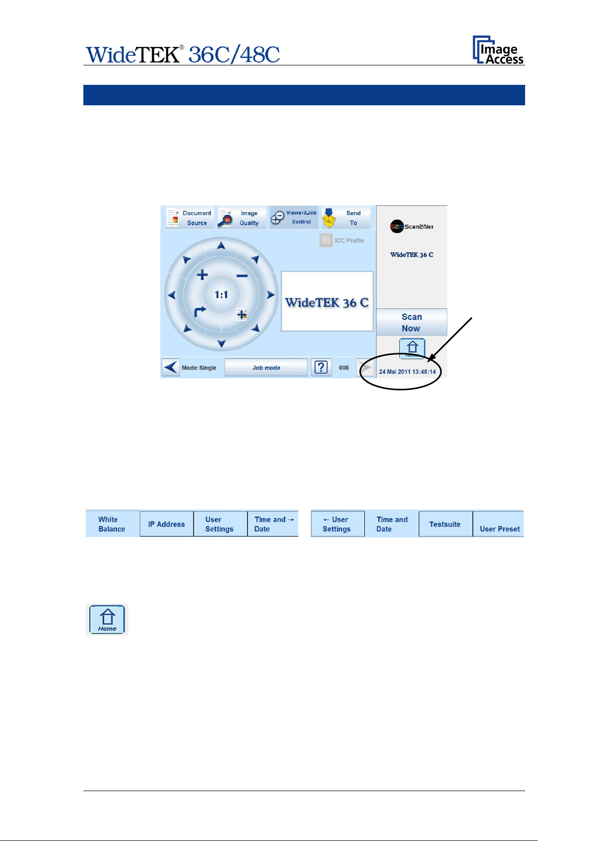
D Setup and Adjustments
The WideTEK® 36C / WideTEK® 48C allow some adjustments directly via the touch
screen, e.g. auto focus setting and White Balance calibration.
Furthermore, the IP address can be configured and other user settings can be defined.
To enter the setup menu, touch the touchscreen at the date and time section ten times
successively.
Picture 35: Viewer & Job Control screen
Please note: The screenshots are taken from a WideTEK® 36C; they represent both
scanner versions.
The screen will change and shows the first screen of the setup menus.
The head line shows four of the six available setup menus.
The small arrow in the menu User Settings indicates that the head line can be scrolled to
show also the other menu items.
Picture 36: Setup menu items
The small arrow changes its position when the head line has been scrolled.
Touching the Home button returns the touchscreen fr om the s et up m enu to
the Kiosk application menu.
Setup Manual Page 39
Page 40

D.1 White Balance
The White Balance function is the most important function for consistent image quality.
With the White Balance function changes in the scanned documents can be
compensated. To get the best quality while scanning, it is rec ommended to execute the
White Balance function in regular intervals.
D.1.1 Information about the White Balance Function
The scanner has an integrated light source with known and stable quality, existing of white
LEDs of the most current design.
At the first step during the white balance the scanner’s sensibility is set in a way that the
brightest zone results in a nearly saturated output signal level. This ensures that the
maximum sensitivity range is used.
After this adjustment, irregularities in the light distribution can be measured. These
irregularities can be caused by ambient light source, by irregularities in the optic or from
uneven brightness of the illumination.
The result of this measurement results in a corrective function, which will set the
brightness over the whole scan area to a consistent level.
The reference target used for the white reference function has an important influence at
the result of the white balance. The white reference target consists of a material which
diffuses the light of the camera. If the test target has wrinkles or dirt visible to the eye on it,
they are also visible for the camera. These areas will be over-compensated.
Although the internal software can eliminate those faults up to a certain degree, it comes
to unfavorable results if the reference target does not exist of the defined quality.
Is the reference target of the defined quality, the scanner will be successf ully calibrated.
Calibration means, that the “White” of the reference target with the described illumination
results in a “White” at the digital output.
The r egu lar p erf orm ance of the white balance function is recommended in order to obtain
the best scan results.
Page 40 Setup Manual
Page 41

D.1.2 Performing the White Balance
Picture 37: Setup menu, start screen
The first menu item of the setup menus is the White Balance screen.
Whenever it is necessary to perform a White Balance calibration, the touchscreen shows
how to position the reference target for optimal calibration.
Place the reference target WT36A-WA-01-A as shown. The reference target is delivered
with the scanner.
Touch the Calibrate button.
During the calibration sequence the reference target will be transported forward and
reverse.
The calibration sequence will take approximately 15 seconds.
At the end of the calibration sequence, the results will be displayed on the touchscreen
and the reference target will be parked at the document table.
Press at the button Remove white balance data to delete the white balance data.
Repeat the white balance measurement after deleting the former data.
Setup Manual Page 41
Page 42

D.2 IP Address
Picture 38: IP Address mask
To change or define the numeric values which make up an IP address , touch the number
in the respective line of IP address, gateway or netmask.
An additional window opens where a numeric keyboard allows
changing the selected value.
Touch the desired position in the respective row to move the
cursor to that position.
To delete a digit, move the cursor to the right of the digit and
press the “<=” button. Digits will always be deleted from right
to left.
The keys arrow left and a rrow right beside the “0” move the
cursor in the line.
Touch Ok button to complete the entry.
Set network settings Saves the new or modified values when pressed.
Reset to Factory Resets all network parameters to factory default settings.
Reset network settings Resets all network parameters to previously defined value
when pressed.
If a WLAN module is installed in the scanner, the name and the IP address will be
displayed below the line Enter new netmask.
Device type and the firmware version are displayed in the bottom line of the screen.
Page 42 Setup Manual
Page 43

Language selector
The touchscreen menu language can be selected by
nguage completes the
setup menu mostly
The changing of the language will be activated after touching
D.3 User Settings
Picture 39: User Settings menu
The User Settings menu allows defining the touchscreen menu parameters.
The currently selected language is displayed.
touching the selection arrow. A list opens, showing the
available languages.
Touching the name of the desired la
selection.
Please note: The language of the
remains in English.
the Home button.
Default Returns all scanner settings to default values.
Change GUI Opens a menu window, which shows the predefined settings
(presets) and allows selecting one of these. Chapter D.3.1
provides more details.
Configure GUI Selection Opens a menu window that shows all available predefined
settings, with a checkbox before the name. Chapter D.3.2
describes more details.
Setup Manual Page 43
Page 44

Display standby after Sets the time of inactivity after the external
display and the touchscreen switches to
standby. The touchscreen and the external
display turn to black.
They will return after pressing the standby
button or touching the touchscreen.
Screen Saver after Sets the time of inactivity after the screen saver
is activated.
Device standby after Sets the time of inactivity after the scanner
switches to standby mode. Click at the selection
arrow and select the value from the list.
It is recommended to restart the scanner after changing the standby settings.
Volume Click at the selection arrow to set the volume for audio
signals.
Show Application menu To show the application menu when starting the scanner,
click at the checkbox.
A little checkmark in the checkbox indicates when the
function is activated.
Set Application as default To activate automatically the application when starting the
scanner, click at the checkbox.
A little checkmark in the checkbox indicates when the
function is activated.
Page 44 Setup Manual
Page 45

D.3.1 Change GUI
Picture 40: Selectable presets
The Change GUI menu shows all predefined settings (presets). By default, the presets
Easy and Expert are defined.
Selecting App Selection switches the touchscreen to the system start screen, followed by
a selection screen with the presets.
After selecting one of the presets, the scanner starts in Job Mode with the selected
preset.
To return to the previous screen without selecting any preset, touch the Back button.
D.3.2 Configure GUI Selection
Picture 41: Presets selection screen
All presets are displayed. The checkbox in front of each entry defines whether the
respective preset is displayed in the Change GUI screen.
After selecting the desired presets, touch the Back button to return to the previous screen.
Setup Manual Page 45
Page 46

Application menu will not be displayed when the scanner starts.
Application menu will be displayed when the scanner starts.
Application will not be used as standard when the scanner
Application will be used as standard when the scanner starts.
D.3.3 Show Application menu
To show the application menu on the touchscreen when starting the scanner, activate this
setting.
Tap the checkbox in front of Show Application menu.
D.3.4 Set Application as default
To switch directly to the selected application when starting the scanner, activate this
setting.
Tap the checkbox in front of Set Application as default.
starts.
Page 46 Setup Manual
Page 47

D.4 Time and Date
Picture 42: Time and date
To change time or date value, touch the value in the respective line.
Touch the line at the desired position to move the “cursor”.
To delete a digit, place the cursor at the r ight side of the digit and press the “<=” b utton.
The digits will always be deleted from right to left.
Use the numeric keypad in order to enter digits.
Selecting the time zone
By changing the time zone, the time that appears on the touc hscreen is quickly adapted to
the location of the scanner.
Touch the selecting arrow. A list with the available values opens.
Tap at the desired time zone. The zone will be set and the list closes.
Store time and date: Saves the modified values when pressed.
Reset time and date: Sets the values to default values when pressed.
Setup Manual Page 47
Page 48

D.5 Testsuite
Picture 43: Testsuite screen
This function will be used for testing purposes.
Furthermore the screen shows some status information of the scanner.
Lamp on: Switches the integrated lamps permanently on. While the lamps are
illuminated, the text on the button changes to Lamp off.
Push the button again to switch the lamps off.
EMV Test: This button starts the EMV test function.
EMV test function means, that the scanner scans permanently without any
additional operator action.
Starting the EMV test:
Insert an appropriate document, for example the CSTT-1 test target which
comes with the scanner.
Push the EMV Test button.
The document will be transported through the scanner and scanned. After a
defined length the transport stops and the document will be transported in
reverse direction. This sequence will be repeated continuously.
Stopping the EMV test:
Push the Home button.
The test mode will be stopped and the touchscreen returns back to the
kiosk application.
Page 48 Setup Manual
Page 49

D.6 User Preset
Picture 44: User preset screen
The User Preset menu is for presets and applications (GUI) selection.
Preset Selection
Presets contain controls for the scan parameters available in the touchscreen. By default,
two presets are defined.
Easy Contains only the basic elem ents of the kiosk application. This preset allows
modifying only a few parameters.
Expert Contains all elements of the kiosk application and allows control of all scanner
parameters.
GUI Selection
The applications (GUI) contain individual elements, e.g. logos and control elements, which
allow adapting the touchscreen to specific needs.
Applications can be created by system administrators.
The application EasyScan is installed as default.
Setup Manual Page 49
Page 50

Create
Opens a screen with a keyboard. Enter the name for the new preset.
↑
Shifts the keyboard between upper case and lower case characters.
⇐
Deletes the character left of the cursor.
123 / abc
Shifts the keyboard between numeric and letter layout. All s pe c ial characters
← or →
Moves the cursor while typing in the input field.
Apply
Saves the new preset.
Cancel
Returns to the former screen.
D.6.1 Preset Selection – Create Preset
User defined presets can be created in a few steps.
Picture 45: Keyboard on the touchscreen
remain at the same position.
Page 50 Setup Manual
Page 51

The touchscreen changes from the setup
D.6.2 Preset Selection – Configure Preset
Select the preset which should be configured from the list Preset Selection.
Touch the button Configure Preset to define the elements which should be displa yed in
the selected preset.
menu to the kiosk application.
The status section on the right side of the
kiosk application shows the message:
Configure GUI
Picture 46: Selecting the preset content
D.6.2.1 Activating a function in the menus
Select a menu from the menu list on top of the touchscreen.
Touch one of the displayed buttons or controller near the respective title and hold it for at
least three seconds. Release the button.
A small additional window opens, showing in three lines
• the title of the selected button or controller,
• the action called by the button,
• the buttons Ready and Cancel in the last line.
The first line always shows Disable <name of the selected function>.
Disable: Disables the s elected function.
Enable: Enables the selected function.
Setup Manual Page 51
Page 52

Touch the selection arrow in the first line to change to Enable. This will show the available
functions in the second line.
Touch the selection arrow in the second line to show the available list of functions.
Extensions behind the function names:
(a) Automatically switches between button, controller or list when the function is
displayed on the touchscreen.
(b) Displays the function always as a button on the touchscreen.
Touch Ready to save the selected function.
Touch Cancel to abort.
D.6.2.2 Saving the preset functions
After selecting the desired controller and buttons, return to the setup menu.
Tap the date and time section 10 times.
Change to the User Presets menu (see Fehler! Verweisquelle konnte nicht gef unden
werden.).
Touch the Save button. This will save the preset with the defined name.
Page 52 Setup Manual
Page 53

D.6.3 Preset Selection – Delete Preset
All presets can be deleted except the pre-installed presets Easy and Expert.
Select the preset to be deleted from the list.
Touch the Delete Preset button. The preset will be deleted.
The list of presets will not a uto m at ic ally r efresh.
To refresh the list, return to the kiosk application (see D.6.5) and open the setup menu
again.
D.6.4 GUI Selection – Delete GUI
All applications can be deleted except the pre-installed application EasyScan.
Select the application to be deleted from the list.
Touch the Delete GUI button. The application will be deleted.
The list of applications will not automatically refresh.
To refresh the list, return to the kiosk application (press the Home button) and open the
setup menu again.
D.6.5 Back to the Kiosk Application
Touch the Home button.
The touchscreen returns to the kiosk application.
Setup Manual Page 53
Page 54

E Poweruser Level
To enter the Poweruser level, start your browser and enter the IP address of the scanner.
Picture 47: Scan2Net Start Screen
The start screen shows three symbols, which lead to the main categories of the Scan2Net
user interface.
Launch Scan Application changes to the main screen of the user interface.
Setup Device changes to the setup menu. Starting with the following chapter, the basics
of the scanner configuration will be described.
Information shows a list of basic information about the scanner, e.g. serial number, the
firmware version, the IP address and many more.
Select Setup Device to open the Setup menu.
Page 54 Setup Manual
Page 55

E.1 Setup Menu
The login level scr een shows the buttons of the login level. All login levels except the level
User are password protected.
The button Launch Scan Application starts the Scan2Net scan application.
The button Back returns to the former screen.
Picture 48: Login level screen
E.1.1 Selecting the Login Level
User This level allows the user to get some status information from the scanner.
These are e.g. the firmware version, the remaining lamp operating time,
system information, and many more. Furthermore it allows setting a few
basic parameters.
Poweruser Password protected level. This level allows setting an extended range of
system parameters and to execute some adjustments. It includes all
parameters of the User level.
Admin Password protected level. This level allows setting all system parameters
and to configure the scanner in detail.
Access to the Admin level is limited for trained technicians. It includes all
parameters of the User level and the Poweruser level.
For the steps described here, choose the login level Poweruser .
Enter as user name and password: Poweruser
Consider the case sensitivity of user name and password.
Click the button Apply to finish the entry.
Setup Manual Page 55
Page 56

E.2 Main Menu
The main menu of the Poweruser level contains all menus of the User level.
The Poweruser start screen is structured in six sections.
Picture 49: Main menu Poweruser level
The buttons below the section titles name the parameters which can be set or modified in
the respective section.
The section Device Information is also available from the User level.
The sections are sorted according to their fr equency of use. Parameters often used are
found in the upper sections. Parameters with lower priority are present in the middle
sections.
The Set-and Reset-Functions can be found in the bottom sections.
Page 56 Setup Manual
Page 57

E.2.1 Navigating through the menus
The bottom line of each screen shows two buttons at the right side:
Setup Menu Returns to the login screen.
Launch Scan Application Switches to the main screen of the integrated Scan2Net
user interface
In each selection menu screen below the parameter to be set, the following button is
displayed:
Back to Main Menu Returns to the Poweruser level start menu (Picture 49).
The log file section (Adjustments & Support Log Files) contains two more buttons:
Download Downloads the currently displayed log to a text file with the
extension “log”.
Back to Log File Menu Returns to the previous menu, where the desired log file
can be selected.
If data files can be selected and transferred within a menu, the menu contains the button
Send File Transfers the selected data file to the scanner, e.g. if a
firmware update is executed.
To install an option, a unique key code must be entered. The respective menu contains
the button
Apply Transfers the unique key code of the option to the scanner.
Screens which show the result of measurements show the following buttons:
New Values Repeats the measurement and shows the result.
New with software 6.x or higher
Always click at this button when leaving the setup menu
to avoid unauthorized use of the setup features.
Setup Manual Page 57
Page 58

E.3 Device Information
The section Device Information gives basic information about the scanner. This section
is divided in two parts.
E.3.1 Device Info
Device Info lists the hardware components and provides information about the settings
for printer configuration, SMB configuration and many more. To find the information, click
the respective links.
Picture 50: Device Info
E.3.2 Operation Info
Operation Info shows the scan counters and provides information about operating times
of the scanner and the lamps.
Picture 51: Operation Info
Page 58 Setup Manual
Page 59

E.4 Base Settings
The Base Settings section contains the basic parameters of the scanner.
E.4.1 User Settings
The section User Settings is divided into subsections.
The User Settings start screen is the Power Saving screen. The following descript ion
starts with the Language Selection screen.
E.4.1.1 Language Selection
Use the function Language Selector to set the language for the Scan2Net user interface.
Picture 52: Language selector
Click on the selection arrow and the list of available languages opens.
Click on the desired language. The change will be executed immediately. All texts and
messages will be displayed in the selected language.
To return to the previous screen click the button Back to Main Menu .
Setup Manual Page 59
Page 60

E.4.1.2 File Name
Please note: Available from firmware version 6.08.
Use the function File Name to define a default name which is.
Picture 53: File name
When defining the default name, variables can be used. To get a list of the variables, click
at the link Wildcard characters.
Picture 54: List of wildcard characters
Below the field “File Name” the defined file name is displayed. To show the file name with
the defined variables, reload the page.
Page 60 Setup Manual
Page 61

Standby mode
Available values
E.4.1.3 Power Saving
Note: The Power Saving screen is the start screen of the User Settings section.
Use the function Power Saving t o set the timers for the standby modes. Three settings
can be defined.
Click on the link Power Saving.
Picture 55: Power Saving
Click on the selection arrow to open the list of available values for the respective standby
mode. The list of available values varies with the selected standby mode.
Device standby
Display standby
Screen Saver
Standby Method
“Never” disables the power save function of the respective menu item.
To return to the previous screen click the button Back to Main Menu .
Setup Manual Page 61
Page 62

E.4.1.4 Transport Speed
Two transport speeds are available.
Use the function Transport Speed to set the values.
Picture 56: Transport speeds
Click at the selection arrows to display the speeds available for the setting Slow and
Normal.
Page 62 Setup Manual
Page 63

E.4.1.5 Volume Use the function Volume to set the level of the loudspeakers volume in the scanner.
Picture 57: Volume level
A screen opens and shows a graphic to symbolize the volume.
Click at the scale to set the volume level or right-click with the mouse at the arrow and
move it to the desired value
To return to the previous screen click the button Back to Main Menu .
Setup Manual Page 63
Page 64

E.4.1.6 Start Button Timeout
Click on the link Start Button Timeout t o set delay between pressing the start button and
the start of the scan sequence.
Picture 58: Start Button timeout
Click at the selection arrows to display the available settings for the delay.
Click at the desired value to set the time-out period.
Page 64 Setup Manual
Page 65

To change the resolution, click the selection arrow in the line
To link an ICC profile to the monitor, click the selection arrow
The ICC profiles available will be displayed. Select the desired
E.4.1.7 Display
Use the function Display to define the resolution of the external monitor and to select an
ICC profile.
Picture 59: Display parameters
The scanner can be equipped with an external monitor. If an external monitor is
connected, parameters for the monitor can be set here.
Display Resolution.
Select the desired resolution from the list.
Restart the scanner to activate the setting.
in the line ICC Profile.
profile.
Restart the scanner to activate the setting.
Setup Manual Page 65
Page 66

E.4.1.8 Splitting Start Page
Use the function Splitting Start Page to define the page which is displayed first, when
Splitting Image is set to Auto in the user interface.
See the Operation Manual, description of Properties Splitting Image.
Picture 60: Splitting start page
The selected start page is highlighted.
Click on the radio button to change the selected page.
Page 66 Setup Manual
Page 67

E.4.1.9 Secure File Erasing
Available from firmware version 6.x
Use the function Secure File Erasing to select a secure erasing algorithm which is used
when deleting files from the scanner’s memory.
Picture 61: List of erasing methods
Click the selection arrow to open the list of the available erasing methods.
Click on the desired method in the list.
Setup Manual Page 67
Page 68

E.4.1.10 Document Cache
The data which will be generate while scanning can be stored either on the RAM Disk or
on the hard disk of the scanner.
Picture 62: Document cache selector
Click on the radio button to select the desired storage media when scanning in Job mode.
RAM disk: Default setting:
Images will be stored in Job mode only in the RAM disk.
That means: Power off Data gone
When the Job mode is finished, the data will be deleted automatically.
Harddisk (volatile mode): The data will be stored at the integrated hard disk.
The advantage in comparison to RAM disk is that a greater amount of images can be
stored on the hard disk.
That means: Power off Data gone
When the Job mode is finished, the data will be deleted automatically.
Harddisk (persistent mode): The data will be stored permanently at the hard disk.
This mode is used is used in conjunction with applications that open more than one job at
the same time.
Page 68 Setup Manual
Page 69

Yes
With factory settings, the scanner’s touchscreen shows at the end of the start
the scanner starts with the selected
No
At the end of the start sequence the touchscreen does not show the selection
Yes
The scanner starts with the application selected in Updates & Uploads
No
At the end of the start sequence the touchscreen shows the Scan2Net
E.4.1.11 Kiosk App
Use the function Kiosk App to define how the scanner behaves when starting.
Show Application menu:
sequence the buttons for the applications EasyScan and Scan2Net.
By touching the respective button,
application.
screen.
Set Application as default:
Java Apps.
See chapter E.5.4
application.
Picture 63: Kiosk App selection
Setup Manual Page 69
Page 70

E.4.1.12 Show Warnings
Use the function Show Warnings to set warning messages on or off in the Scan2Net user
interface.
Picture 64: Show Warnings selector
E.4.1.13 Validate Certificates
Select Yes to activate the validation of certificates when scanning.
Picture 65: Validate Certif icat es sel ect or
Page 70 Setup Manual
Page 71

Manual
Allows setting the IP address, subnet mask, and default gateway manually;
DHCP
Sets the values for IP address, subnet mask, and default gateway
automatically, depending on the existing network where the scanner is
For detailed
rk before
E.4.2 Network Configuration
The section Network Configuration is divided in subsections.
The Network Configuration start screen is the IPv4 (Network Interface 0) screen, which
is described in chapter E.4.2.2. The following description starts with the IP Configuration
Method screen.
E.4.2.1 IP Configuration Method
The function IP Configuration Method allows the operator to select between two
methods of IP configuration of the scanner.
Picture 66: IP Configuration Method
corresponding to the network where the scanner will be used.
After modifying the above named values, the connection to the scanner
must be restored with the new data.
installed.
A DHCP server must be accessible in the network.
information, ask the network administrator of the local netwo
selecting the DHCP method.
When selecting DHCP the connection to the scanner is lost. The
connection to the scanner must be restored with the new data.
Important for the next steps:
After changing the network settings, enter the new IP address of the scanner in your
browser and reopen the Poweruser main menu as previously described.
Setup Manual Page 71
Page 72

IP address
Enter the IP address which should be used by the scanner.
Subnet Mask
Enter the value for the subnet mask.
Default Gateway
Enter the value for the gateway. In most cases this is the IP
E.4.2.2 IPv4 (Network Interface 0)
The function IPv4 (Network Interface 0) allows the operator modifying the parameters for
the “Network Interface 0”. This is the primary network and is used for communication with
external network devices.
Picture 67: Settings of IPv4 (Network Interface 0)
The screen shows the parameters for “Network Interface 0”.
address of the scanner.
After modifying the network parameters, click on the Apply button to transfer the new
settings to the scanner. The scanner is now accessible with its new IP address.
Note: After changing the IP address the connection to the scanner gets lost. Enter the
new IP address in your browser to get re-connected with the scanner.
Depending on the browser used, it is necessary to delete the browser cache
before the scanner is accessible.
Page 72 Setup Manual
Page 73

IP address
Enter the IP address for the “Network Interface 1”.
Subnet Mask
Enter the value for the subnet mask.
Default Gateway
Enter the value for the gateway.
E.4.2.3 IPv4 (Network Interface 1)
The function IPv4 (Network Interface 1) allows the operator modifying the parameters for
the “Network Interface 1”. This is the secondary network and used for communication with
internal network devices, e.g. the WLAN module.
Picture 68: Settings of IPv4 (Network Interface 1)
The screen shows the parameters for the “Network Interface 1”.
The IP address 10.0.0.50 is pre-configured for the communication with the WLAN module.
Default IP address of the WLAN module: 10.0.0.1.
After modifying the network parameters, click on the Apply button to transfer the new
settings to the scanner. The “Network Interface 1” is now accessible with its new IP
address.
Note: Depending on the browser used, it is necessary to delete the browser cache
before the scanner is accessible.
Setup Manual Page 73
Page 74

E.4.2.3.1 Solving a routing conflict in a network
As said before, the “Network Interface 0” is used for the communication with external
networks; “Network Interface 1” is used for the internal communication with the WLAN
module.
If the scanner should be operated in an existing network that is configured in the IP
address range 10.0.0.x/24 or 10.0.x.x/16 and a host with the IP address 10.0.0.1 is used
in this network, a routing conflict will occur.
In the following example the IP address of the WLAN module will be changed to the IP
address 172.16.0.1.
To solve the routing conflict, the following steps must be executed in the described order:
1. Note the network settings of the existing network, in which the scanner should be
integrated.
2. The “Network Interface 0” parameters of the scanner must be set temporarily to
factory values. This can be done directly from the touchscreen (see chapter D.2).
IP address: 192.168.1.50
Subnet mask: 255.255.255.0
Default gateway: 192.168.1.50
3. Connect the scanner directly with a PC. The network parameters of the PC must
allow accessing a network with the address range 192.168.1.x.
4. Start the scanner and select the Poweruser setup level.
5. Select Base Settings Network Configuration Wireless LAN (DHCP). See
chapter E.4.2.10.
6. Set the DHCP client range to 172.16.0.51 – 172.16.0.251. Click the Apply button.
7. Select Base Settings Network Configuration Wireless LAN (LAN Interface). See
chapter E.4.2.8. Set the parameters for the WLAN module as follows:
IP address: 172.16.0.1
Subnet mask: 255.255.255.0
Default gateway: 172.16.0.1
Click the Apply button. The connection to the WLAN module gets temporarily lost.
8. Select Base Settings Network Configuration IPv4 (Network Interface 1). See
chapter E.4.2.3. Set the parameters for “Network Interface 1” as follows:
IP address: 172.16.0.50
Subnet mask: 255.255.255.0
Default gateway: 172.16.0.50
Click the Apply button. The connection between WLAN module and scanner is now
accessible.
9. Select Base Settings Network Configuration IPv4 (Network Interface 0). See
chapter E.4.2.2. Enter the previously noted parameters according to the network in
which the scanner should be used.
Page 74 Setup Manual
Page 75

Domain Name
Enter the domain name here.
Primary DNS Server
Enter the address of the primary DNS server here.
Secondary DNS Server
Enter the address of the secondary DNS server here.
E.4.2.4 Domain Name Server
This section defines the parameters for the Domain Name Server.
Picture 69: Domain Name Server parameters
Setup Manual Page 75
Page 76

SMB Hostname
Enter an SMB host name to identify the scanner in the
Use SMB hostname as
Select “Yes” if the SMB host name should be used as
SMB Workgroup
Enter the SMB workgroup in which the scanner is
WINS Server
If a WINS server is used, enter the IP address of the
Use NTLMv2 Authentication
Select either Yes or No.
SMB Protocol Version
Select from the settings offered in the list. The
recommended operation systems for the protocol
Trust server-provided hints
No: Recommended
Send principal to Windows
No: Recommended, higher security.
E.4.2.5 SMB Settings
This section defines the parameters for the SMB Settings.
Picture 70: SMB Settings
Note: The default settings are recommended.
network. Default is the MAC address of the scanner.
DHCP name
client name for DHCP.
installed.
server or \\<Server name> here.
version are named in brackets.
for kerberos tickets
Yes: Can be used with older Windows server systems
2008 Server (and later)
Yes: Low security, but higher compatibility.
Page 76 Setup Manual
Page 77

allow all
No restriction for the use of the protocol
allow only for
Enter the IP address or the address range in CIDR notation for the
block all
Blocks all communication for the protocol.
E.4.2.6 Firewall
This section allows setting the firewall parameters.
Picture 71: Firewall settings
The standard ports for the protocols are displayed in brackets.
devices which are allowed to use the protocol.
CIDR notation means e.g. 192.168.0.x/24 or 172.16.x.x/16.
After modifying the values click at the Apply button to transfer the modified settings.
Setup Manual Page 77
Page 78
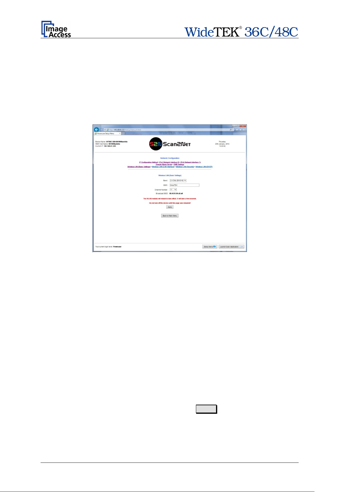
Band
Click on the selection arrow to open the list.
SSID
Enter a name to identify the WLAN of the scanner.
Channel Number
Auto: Recommended setting. Uses the channel with the best data
Broadcast SSID
The broadcast SSID is set automatically.
Note: The menus described in chapters E.4.2.7 to E.4.2.10 concerning the wireless
LAN configuration will only be displayed if a WLAN module is installed in the
scanner.
E.4.2.7 Wireless LAN (Basic Settings)
Use the function Wireless LAN (Basic Settings) to define the basic settings for the
WLAN module.
Note: T his menu is displayed only if a WLAN module is installed and if the settings for
IPv4 (Network Interface 1) and Wireless LAN (LAN Interface) fit togethe r.
Picture 72: Wireless LAN Basic Settings
Note: The default settings are recommended.
Select from the list the desired band for the WLAN communication.
transfer performance.
To use a specific channel, click the selection arrow and select the
desired channel from the list.
After modifying the WLAN parameters, click at the Apply button to transfer the new
settings.
Follow the note regarding the reboot sequence.
Page 78 Setup Manual
Page 79

IP address
Enter the IP address of the secondary LAN interface of the
Subnet Mask
Enter the value for the subnet mask.
Default Gateway
Enter the value for the gateway.
E.4.2.8 Wireless LAN (LAN Interface)
Use the function Wireless LAN (L AN Interface) to define the parameter of the secondary
LAN interface of the motherboard. This interface is used to connect the Wireless LAN
module with the motherboard..
Note: T his menu is displayed only if a WLAN module is installed and if the settings for
IPv4 (Network Interface 1) and Wireless LAN (LAN Interface) fit together.
Picture 73: Wireless LAN (LAN Interface)
motherboard.
After modifying the network parameters, click on the Apply button to transfer the new
settings to the scanner. The scanner is now accessible with its new IP address.
Setup Manual Page 79
Page 80

Encryption
None: No encryption, no security.
Recommended. Encryption according to the
Pre-Shared Key Format
Select between Passphrase and HEX (64 characters).
Pre-Shared Key
Enter a string as pre-shared key here.
E.4.2.9 Wireless LAN (Security)
Use the function Wireless LAN (Security) to define the parameters for wireless LAN
security.
Note: T his menu is displayed only if a WLAN module is installed and if the settings for
IPv4 (Network Interface 1) and Wireless LAN (LAN Interface) fit together.
Picture 74: Wireless LAN (Security)
The screen shows the parameters for wireless LAN security.
WPA 2:
WPA 2 standard, high security.
After modifying the parameters, click on the Apply button to transfer the settings to t he
scanner.
Page 80 Setup Manual
Page 81

E.4.2.10 Wir ele s s LAN (DHCP)
Use the function Wireless L AN (DHCP) to define the rang e of IP addresses that can be
used by the WLAN module for DHCP access.
Note: T his menu is displayed only if a WLAN module is installed and if the settings for
IPv4 (Network Interface 1) and Wireless LAN (LAN Interface) fit together.
Picture 75: Wireless LAN (DHCP)
Click in the corresponding fields and enter the start IP address and the end IP address to
define the address range that can be used.
Setup Manual Page 81
Page 82

E.4.3 Adjust Time & Date
The section Adjust Time & Date is divided into subsections.
The Adjust Time & Date start screen is the Manual Adjustment screen. The following
description starts with the Time Format screen.
To set the time correctly for the scanner, make the adjustments in the following order.
Select the time zone. See chapter E.4.3.2.
Set your local time with the manual adjustment. See chapter E.4.3.3.
Establish a connection to an NTP server. See chapter E.4.3.4.
Page 82 Setup Manual
Page 83

Time Format 12h
Time Format 24h
E.4.3.1 Time Format
The time shown in the headline of the Scan2Net user interface can be displayed in either
12h or 24h format.
Picture 76: Time Format
Click on the selection arrow. The differences between 12h and 24h format are shown
below.
Display from
00:00 to 11:59
Display from
12:00 to 23:59
Setup Manual Page 83
Page 84

E.4.3.2 Time Zone
Use the function Tim e Zone to define the time zone for the internal clock of the scanner.
Picture 77: Time Zone screen
Click on the selection arrow. A list opens.
Select the desired time zone f rom the list. The list will close and the selected setting is
effective immediately.
Page 84 Setup Manual
Page 85

E.4.3.3 Manual Adjustment
Use the function Manual Adjustment to set time and date to be displayed in the headline
of the Scan2Net user interface.
Picture 78: Manual Adjustment
To set a value, click on the selection arrow beside the respective value.
Select from the list. The new value will be transferred directly to the system clock and is
displayed in the headline of the Scan2Net interface.
Setup Manual Page 85
Page 86

E.4.3.4 NTP Server
Use the function NTP Server to define the address of time server.
Picture 79: NTP Server setting
To connect to a NTP server, the scanner must have a connection to the internet.
Ask your network administrator for special information concerning your local network.
Enter the address of the NTP server in the line NTP server. It is a necessary requirement
that your local network enables the scanner to connect with the internet.
Page 86 Setup Manual
Page 87

E.4.4 Sound System
The section Sound System is divided into three subsections.
The Sound System start screen is the Set Volume screen.
E.4.4.1 Set Volume
Use the function Set Volume to set the loudspeakers volume of the scanner.
Picture 80: Set Volume
A screen opens and shows a graphic to symbolize the volume level.
Click at the scale to set the volume level or right-click with the mouse at the arrow and
move it while holding the mouse button pressed to the desired value.
To return to the previous screen click the button Back to Main Menu .
Setup Manual Page 87
Page 88

E.4.4.2 Sound Files
Use the function Sound Files to list the sounds which are linked to system events.
Picture 81: Sound Files list
Scroll to the bottom of the list to search and upload new sounds to the scanner.
Picture 82: Upload new sound files
Click on the button Search to search the directories of your local PC and/or your
network for sound files.
Click on the button Send File to upload the selected f ile to the scanner. After uploading,
the file will be displayed in the list.
Click on the trash can icon to delete the file.
Page 88 Setup Manual
Page 89

E.4.4.3 Link Events
Use the function Link Events to change the sounds linked to system events.
Picture 83: Link Events list
The sound file that is listed at each event is dependent on the language set for the
scanner (see chapter E.4.1.1).
To identify the language of the sound file, an identifier can be added to t he file name. For
example “en” marks sound files in English language or “de” marks sound files in German
language.
Independent from the language selected for the scanner, every sound f ile can be linked to
every event.
Click on the selection arrow beside the sound file name. A list with all avail able sound files
opens.
Select the desired sound file from the list.
Click on the loudspeaker symbol to play the sound.
Setup Manual Page 89
Page 90

E.4.5 Installed Options
This section shows all available options for the scanner.
After clicking on Install Options and/or Installed Options a screen opens and lists all
options which are available for the scanner. Please be patient as it will t ake a m oment t o
actualize the list.
Picture 84: Options List
To activate an option, a unique key must be entered. The key is valid only with one
specific scanner and cannot be transferred to another scanner.
The software keys can be purchased at the Image Access Customer Service Port al. Visit
the URL portal.imageaccess.de
and enter the data for your scanner to get the available
keys.
Enter the key in the respective line and click on Apply .
After activating the option, its color turns to “Green”, which indicates active options.
Page 90 Setup Manual
Page 91

E.5 Updates & Uploads
In the section Updates & Uploads several updates can be initiated, screensavers can be
defined and installed and Java applications can also be installed. The PDF cover sheet
can be uploaded and activated here as well.
E.5.1 Update Scanner Firmware
Upload a new firmware version to the scanner.
Picture 85: Update Scanner Firmware
The Image Access Customer Service Portal (CSP) at http://portal.imageaccess.de/ offers
firmware updates for every Scan2Net scanner. In order to download the appropriate
firmware version update for your scanner, you must be a registered user. Log in to t he
CSP with your personal login name and password.
Select Actions S2N Device Updates to download the current firmware version.
Follow the steps described on the website. Download the ZIP archive of the current
firmware version to your local PC.
The ZIP archive contents:
• Three “txt” files with information concerning the installation, t he release notes and
the version number.
• One “tar” archive with the firmware
Important: Never unpack the “tar” archive file!
Always send the complete ZIP archive to the scanner!
Setup Manual Page 91
Page 92

In the screen Update Scanner Firmware (see Picture 85) click on the selection arrow
beside “Post update behavior” of the scanner from the list.
Select Reboot from the list. This will start the scanner automatically after the firmware
update sequence is completed.
Browse your local PC and select the previously downloaded firmware update file.
Click the butto n Send File to transfer the selected firmware file to the scanner.
Important: Do not switch off the scanner while executing the firmware update!
Transferring the firmware file can take a couple of minutes, depending on the network
performance. While the update is running, no messages will be displayed on the screen.
After the firmware is successfully updated, the screen displays a summary.
To finalize the update process, the scanner must be rebooted. This is done automatically
if Post Update Behavior is set to Reboot.
It Shutdown is selected, the scanner powers down at the end of the firmware update.
When restarting after a firmware update, the scanner reboots with factory default settings.
Note: A White Balance adjustment must always be executed after a firmware update.
See chapter D.1 for more information about the White Balance adjustment.
All installed options will stay active.
Page 92 Setup Manual
Page 93

Click the button to search the directories of your local PC and/or your
Click the button to load the selected file to the scanner.
E.5.2 ICC Profiles
The section ICC Profiles is divided into the subsections Scanner Profile,
Monitor Profiles, and Printer Profiles.
ICC profiles are integrated in the image file data.
First of all, download the respective ICC profile for the device to your local PC.
E.5.2.1 Scanner Profile
The ICC profile loaded at Scanner Profile adapts the color space between scanner and
image editing software.
Select Scanner Profile to upload an ICC profile to the scanner.
Picture 86: Scanner Profile
Search
network for ICC profile files.
Send File
After uploading, the ICC profile will be displayed.
Activating the ICC profile:
Select ICC Profiles in section Quality of the ScanWizard user interface.
Setup Manual Page 93
Page 94

Picture 87: ICC Profile installed
To delete the ICC profile, click on the “Delete” symbol.
To get information about the ICC prof ile, click on the information symbol
Picture 88: ICC Profile information
Page 94 Setup Manual
Page 95

Click the button to search the directories of your local PC and/or your
Click the button to load the selected file to the scanner.
E.5.2.2 Monitor Profiles
The ICC profile will be adapted to the image data displayed at the external monitor of the
scanner.
Select Monitor Profiles to upload an ICC profile for the external monitor.
Picture 89: Monitor Profiles
Search
network for ICC profile files.
Send File
After uploading, the ICC profile will be displayed.
Selecting the ICC profile to be used:
Select section User Settings, function Display (see chapter E.4.1.6) and select the ICC
profile as described.
Setup Manual Page 95
Page 96

To delete the ICC profile, click on the “Delete” symbol.
To get information about the ICC profile, click on the information symbol
Picture 90: ICC Profile information
To activate the ICC profile for the external monitor, select the menu Viewer & Job
Control in the touchscreen and mark the checkbox for the ICC Profile.
Picture 91: Touchscreen menu, ICC profile selected
Page 96 Setup Manual
Page 97

Click the button to search the directories of your local PC and/or your
Click the button to load the selected file to the scanner.
E.5.2.3 Printer Profiles
The ICC profiles for printers adapt t he color space of the scanner to the color space of the
printer used with the scanner.
Select Printer Profiles to upload an ICC printer profile.
Picture 92: Printer Pro fi les
Search
network for ICC profile files.
Send File
After uploading, the ICC profiles will be displayed.
Setup Manual Page 97
Page 98

To delete the ICC profile, click on the “Delete” symbol in the line of the ICC
profile to be deleted.
To get information about the ICC profile, click on the information symbol in
the line of the ICC profile.
Selecting the ICC profile to be used:
In the S2N user interface of the scanner click on the link Options below the button Copy.
The Printer Preset window opens. Click on Printing Enhancements .
Select Color Matching ICC Profile.
The additional line ICC Profile is added to the menu below Color Matching.
Click on the selection arrow. All installed ICC profiles will be listed.
Select the desired ICC profile from the list.
Page 98 Setup Manual
Page 99

To delete a screensaver, click on the “Delete” symbol at the
Background color
Click on the selection arrow to open the list of available colors.
Text color
Click on the selection arrow to open the list of available colors.
Text size
Click on the selection arrow to open the list of available sizes
Edit text
Enter the desired text here.
Upload new
E.5.3 Touchscreen / Desktop
This section is divided in the subsections Touchscreen and Desktop.
E.5.3.1 Touchscreen
This section allows installing a screensaver for the touchscreen. GIF animations are
suitable as screensavers for the touchscreen.
Picture 93: Touchscreen screensaver
The installed screensavers are listed.
right side of the line.
Select the desired background color from the list with a mouse
click.
Select the desired text color from the list with a mouse click.
from 50 to 400. Select with a mouse click.
screensaver
Click on Apply to transfer the text to the scanner.
Click on the Search butt on to search the directories of your
screensaver GIF
local PC and/or your network for a suitable file.
animation
Click on Send File to transfer the selected file to the scanner.
A message signalizes the end of the upload sequence.
To activate the changes, restart the scanner.
Setup Manual Page 99
Page 100

To delete a desktop image, click on the “Delete” symbol at the
Upload new
E.5.3.2 Desktop
This section allows the operator to install desktop images for the external monitor.
Picture 94: Desktop screensaver list
The installed desktop images are listed on the screen.
right side of the line.
Click on the Search button to search the directories of your
desktop image
local PC and/or your network for a suitable file.
Click on Send File to transfer the selected file to the scanner.
A message signalizes the end of the upload sequence.
To see the available desktop image in detail, click on the preview image in the column
“Image”. This shows the image in full size.
Picture 95: Preview of desktop image
Scroll to the bottom of the window and click on Back to Touchscreen / Desktop Menu
to return to the previous screen.
To activate the changes, restart the scanner.
Page 100 Setup Manual
 Loading...