


 Loading...
Setup and Assembly Manual
This device is  compliant.
File: WT36_SetupAndAssembly_F2.doc

2007 – 2010 by Image Access GmbH, Wuppertal, Germany.
Printed in Germany. All rights reserved.
Reproduction in whole or in part in any form or medium without express written permission of Image Access is prohibited. Scan2Net is a registered trademark of Image Access. Other designated brands herein are trademarks of Image Access.
All other trademarks are the property of their respective owners.
Image Access reserves the right to change the described products, the specifications or documents at every time without prior notice. For the most recent version, always check our web site www.imageaccess.de or the customer service portal at http://service.imageaccess.de
Setup and Assembly Manual |
Page 3 |

Introduction
Dear Customer,
We congratulate you on the acquisition of this innovative product from Image Access.
We at Image Access are proud of the work we do; it is the result of our extremely high standards of production and stringent quality control.
With the WideTEK 36, Image Access offers an efficient scanner which covers a wide scope of applications due to its versatility. Its integrated web-based user interface makes all functions available in structured menus.
This manual is designed to lead the user through all necessary assembly and setup steps after the WideTEK 36 has been delivered.
For this reason, we ask you to read this manual attentively before starting with the assembly procedure. By doing so, you will avoid errors from the beginning and you will be able to control all functions easily.
Please also consider the following points:
Damages to your unit may have occurred during shipping. Please check for damages immediately after delivery of the unit. Inform your supplier if damage has occurred.
Read and ensure that you understand the safety notes. They were developed for your protection and safety as well as to protect the unit.
Regular maintenance conserves the high quality and safe operation of the WideTEK 36 during the entire service life.
If you have any further questions, please feel free to contact your local dealer or Image Access directly. Our staff will be happy to help you.
For your daily work with the WideTEK 36, we wish you success and complete satisfaction.
Regards
Your Image Access Team
Page 4 |
Setup and Assembly Manual |

About this Manual
Setup and Assembly Manual
The Setup and Assembly Manual is written for technical staff with some basic mechanical as well as software skills. Many resellers will offer on-site installation; therefore, large parts or all of the setup and assembly manual might not be of interest to the reader. The access level at which the setup and adjustment processes are performed is called “Power user”. This “Power user” level is password protected to prevent access by the normal operator.
All information about the normal operation and behavior of this device is found in the
Operation Manual.
All available manuals for this device can be downloaded from our customer service portal at http://service.imageaccess.de. Be sure to always check for the latest versions of these manuals.
This manual is divided into four sections, A to D. Section A
Note:
Section B
Section C
Section D
Setup and Assembly Manual |
Page 5 |

Version History
Version |
Published in |
Content/Changes/Supplements |
A |
February 2007 |
Preliminary version. |
|
|
Description of the device elements. |
|
|
Description of assembling steps. |
|
|
Description of Scan2Net Firmware Adjustment Procedure. |
|
|
Description of Recovery Function. |
|
|
|
B |
May 2007 |
Additional information concerning cleaning, tests and |
|
|
troubleshooting. |
C |
August 2007 |
Some minor modifications in the text, some new screenshots |
|
|
because of new firmware release. |
D |
August 2008 |
New screenshots because of release of S2N firmware version 5. |
|
|
Minor modifications in detail descriptions. |
|
|
Table D.4 corrected. Changed values for the device weight and |
|
|
total shipping weight. |
|
|
|
E |
May 2009 |
Some minor supplements in detail descriptions. |
|
|
Some screenshots modified. |
|
|
|
F |
December 2009 |
Error code table supplemented, tables of warnings and |
|
|
information have been added. |
|
|
|
F2 |
January 2010 |
Some minor corrections in details description. |
|
|
Chapter D.3 Electr. Spec. New value for stand-by consumption, |
|
|
another power supply is used. |
Page 6 |
Setup and Assembly Manual |

Table of Content |
|
||
Introduction-------------------------------------------------------------------------- |
4 |
||
About this Manual ----------------------------------------------------------------- |
5 |
||
Version History --------------------------------------------------------------------- |
6 |
||
A Hardware Setup -------------------------------------------------------------- |
14 |
||
A.1 |
Content on Delivery ............................................................................................. |
14 |
|
A.1.1 Contents of Floor Stand Box |
15 |
||
A.1.1.1 |
List of Assembling Material and Tools |
15 |
|
A.1.2 |
Floor Stand Overview |
16 |
|
A.1.3 Parts of Floor Stand |
17 |
||
A.2 |
Assembling the Floor Stand................................................................................. |
18 |
|
A.3 |
Combining Floor Stand and Scanner................................................................... |
21 |
|
A.4 |
Connecting to the Power Source ......................................................................... |
25 |
|
A.4.1 Connectors at the Scanner |
26 |
||
A.5 |
Powering up the WideTEK 36.............................................................................. |
27 |
|
A.6 |
WideTEK 36 Touch Panel ................................................................................... |
27 |
|
A.6.1 Starting the WideTEK 36 from Stand-By Mode |
27 |
||
A.6.2 Turning-off the WideTEK 36 |
28 |
||
A.6.3 |
The Help Function |
28 |
|
A.7 |
Navigating through the Screens .......................................................................... |
29 |
|
A.7.1 How to Enter or Change Values |
29 |
||
A.8 |
IP Address Setup................................................................................................. |
30 |
|
A.8.1 IP Address Setup by Touch Panel |
30 |
||
A.9 |
Optical Adjustment............................................................................................... |
32 |
|
A.9.1 |
White Balance |
32 |
|
A.9.1.1 |
Helpful information about the white balance adjustment |
32 |
|
A.9.1.2 |
Performing the White Balance Adjustment |
33 |
|
Setup and Assembly Manual |
Page 7 |

Table of Content, part 2 |
|
||
B Software Setup --------------------------------------------------------------- |
34 |
||
B.1 Start Screen of the Scan2Net User Interface ...................................................... |
34 |
||
B.2 |
Setup Menu ......................................................................................................... |
35 |
|
B.2.1 Selecting the Login Level |
35 |
||
B.3 |
Poweruser Login Level........................................................................................ |
36 |
|
B.3.1 Setup Network IP Address |
37 |
||
B.3.2 Adjust Time & Date |
38 |
||
B.3.3 |
Sound Control |
39 |
|
B.3.3.1 |
Set Volume |
40 |
|
B.3.3.2 |
Wave Files |
41 |
|
B.3.3.3 |
Link Events |
42 |
|
B.3.4 |
Firmware Update |
43 |
|
B.3.5 |
Install ICC Profiles |
45 |
|
B.3.6 |
Install Option |
47 |
|
B.3.7 |
White Balance |
48 |
|
B.3.8 |
Brightness Correction |
50 |
|
C Cleaning, Test and Troubleshooting---------------------------------- |
51 |
||
C.1 |
Cleaning the Transport Drums ............................................................................ |
51 |
|
C.2 |
Cleaning the Glass Plate..................................................................................... |
53 |
|
C.3 |
Replacing the Glass Plate ................................................................................... |
53 |
|
C.4 |
Scan Test Targets ............................................................................................... |
58 |
|
C.4.1 Scan CSTT Test Target |
58 |
||
C.4.2 Scan IT8 Test Target |
59 |
||
C.5 |
Network Analyzer ................................................................................................ |
60 |
|
C.6 |
Recovery Function .............................................................................................. |
61 |
|
C.6.1 Important Notes Before Recovering to Factory Defaults |
61 |
||
C.6.2 How to Recover to Factory Defaults |
62 |
||
C.7 |
Error Codes ......................................................................................................... |
65 |
|
C.8 |
Warnings ............................................................................................................. |
67 |
|
C.9 |
Information .......................................................................................................... |
67 |
|
Page 8 |
Setup and Assembly Manual |

Table of Content, part 3 |
|
|
D Technical Data---------------------------------------------------------------- |
68 |
|
D.1 |
Scanner Specifications ........................................................................................ |
68 |
D.2 |
Ambient Conditions.............................................................................................. |
68 |
D.3 |
Electrical Specifications ....................................................................................... |
69 |
D.4 |
Dimensions and Weight....................................................................................... |
69 |
Setup and Assembly Manual |
Page 9 |

Table of Pictures |
|
Picture 1: Transport box opened ....................................................................................... |
14 |
Picture 2: Floor stand box opened .................................................................................... |
15 |
Picture 3: Assembling material.......................................................................................... |
15 |
Picture 4: Technical drawing of floor stand ....................................................................... |
16 |
Picture 5: Floor stand components.................................................................................... |
17 |
Picture 6: Side pillar in foot profile..................................................................................... |
18 |
Picture 7: Traverse inserted into foot bracket.................................................................... |
18 |
Picture 8: Inserting screws with washer ............................................................................ |
19 |
Picture 9: Bottom and side components assembled ......................................................... |
19 |
Picture 10: Top bracket on vertical leg .............................................................................. |
20 |
Picture 11: Upper traverse inserted................................................................................... |
20 |
Picture 12: Inserting the rod .............................................................................................. |
21 |
Picture 13: Two persons lifting the scanner out of the transport box ................................ |
21 |
Picture 14: Lift the scanner to remove the foam rubber element ...................................... |
22 |
Picture 15:Removing foam rubber element and cardboard element................................. |
22 |
Picture 16: Bottom side, front side left............................................................................... |
23 |
Picture 17: Bottom side, back side left .............................................................................. |
23 |
Picture 18: Fastening the scanner onto the floor stand..................................................... |
23 |
Picture 19: WideTEK 36 placed on floor stand, ready to use............................................ |
24 |
Picture 20: Connectors at WideTEK 36............................................................................. |
26 |
Picture 21: Start menu screen........................................................................................... |
27 |
Picture 22: Touch panel while shut down in progress ....................................................... |
28 |
Picture 23: Keyboard with capital letters ........................................................................... |
29 |
Picture 24: Keyboard with lower case letters .................................................................... |
29 |
Picture 25: Self Test 1 menu ............................................................................................. |
30 |
Picture 26: Network setup ................................................................................................. |
31 |
Picture 27: Numeric key pad ............................................................................................. |
31 |
Picture 28: Confirm changes ............................................................................................. |
31 |
Picture 29: White Balance screen ..................................................................................... |
33 |
Picture 30: Progress indicator ........................................................................................... |
33 |
Page 10 |
Setup and Assembly Manual |
Table of Pictures, part 2 |
|
Picture 31: White balance result ........................................................................................ |
33 |
Picture 32: Start screen ..................................................................................................... |
34 |
Picture 33: Login level screen............................................................................................ |
35 |
Picture 34: Poweruser main menu..................................................................................... |
36 |
Picture 35: Network parameters of the scanner ................................................................ |
37 |
Picture 36: Adjust Time and Date Screen.......................................................................... |
38 |
Picture 37: Sound System screen ..................................................................................... |
39 |
Picture 38: Volume level displayed.................................................................................... |
40 |
Picture 39: List of sound files............................................................................................. |
41 |
Picture 40: Link Sounds to Events screen ......................................................................... |
42 |
Picture 41: Firmware Update ............................................................................................. |
43 |
Picture 42: Summary of successful firmware update......................................................... |
44 |
Picture 43: ICC Profile screen ........................................................................................... |
45 |
Picture 44: Upload ICC Profile screen ............................................................................... |
46 |
Picture 45: Embed ICC profile ........................................................................................... |
46 |
Picture 46: Install Option screen........................................................................................ |
47 |
Picture 47: Click the marked button................................................................................... |
48 |
Picture 48: Select „White Balance“ .................................................................................... |
48 |
Picture 49: White Reference Target on document table.................................................... |
49 |
Picture 50: Selecting “Brightness Correction”.................................................................... |
50 |
Picture 51: Selecting the correction factor ......................................................................... |
50 |
Picture 52: Self Test 1 ....................................................................................................... |
51 |
Picture 53: Transport drums at front and back .................................................................. |
52 |
Picture 54: Hexagon screws at WT 36 backside ............................................................... |
53 |
Picture 55: Hexagon head screw at left side of housing.................................................... |
53 |
Picture 56: Lifting the main cover ...................................................................................... |
54 |
Picture 57: Placing the main cover .................................................................................... |
54 |
Picture 58: Audio connector............................................................................................... |
54 |
Picture 59: Sensor connector ............................................................................................ |
54 |
Picture 60: Controller connector ........................................................................................ |
55 |
Setup and Assembly Manual |
Page 11 |

Table of Pictures, part 3 |
|
Picture 61: Cable connector .............................................................................................. |
55 |
Picture 62: Screw at back, left side ................................................................................... |
56 |
Picture 63: Screw at back, right side ................................................................................. |
56 |
Picture 64: Screw at front, left side.................................................................................... |
56 |
Picture 65: Screw at front, right side ................................................................................. |
56 |
Picture 66: Holding the glass plate rack ............................................................................ |
57 |
Picture 67: Removing the glass plate rack ........................................................................ |
57 |
Picture 68: Position of CSTT target on the document table .............................................. |
58 |
Picture 69: Position of IT8 test target on the document table............................................ |
59 |
Picture 70: Network Analyzer screen ................................................................................ |
60 |
Picture 71: IP address for testing ...................................................................................... |
60 |
Picture 72: Recovery Key.................................................................................................. |
61 |
Picture 73: Position of gap on right side............................................................................ |
62 |
Picture 74: Position of gap on left side .............................................................................. |
62 |
Picture 75: Moving the compensator plate upwards ......................................................... |
62 |
Picture 76: Compensator plate on document table ........................................................... |
63 |
Picture 77: Compensators lifted ........................................................................................ |
63 |
Picture 78: Inserting recovery key ..................................................................................... |
63 |
Picture 79: Connectors on rear panel................................................................................ |
63 |
Page 12 |
Setup and Assembly Manual |

Thiis page iinttenttiionalllly llefftt bllank
Setup and Assembly Manual |
Page 13 |
A Hardware Setup
A.1 Content on Delivery
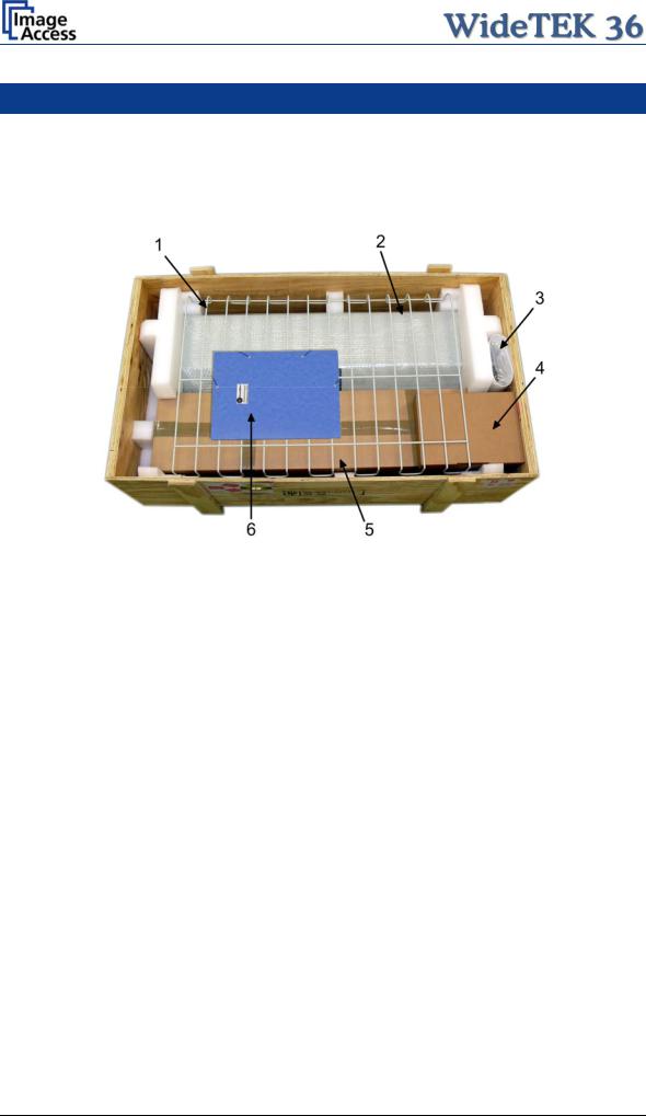
The scanner is delivered in a wooden transport box. The transport box also contains the disassembled floor stand in a separate cardboard box and the paper catch basket.
Picture 1: Transport box opened
1:Paper catch basket
2:Scanner
3:White Reference Target
4:Box with cable set and accessories. The cable set consist of:
Network cable. Connects the scanner to the network. All network parameters such as IP address, subnet mask and gateway must be set via the front panel prior to the first use.
Crossover cable. Connects the scanner directly to a computer via the network card.
Two power cables. US and European standard. Connects the scanner to the wall outlet.
5:Floor stand in separate cardboard box (optional)
6:Folder with CSTT-1 reference targets and the manuals.
Please note: Keep the wooden transport box and the cardboard box for future use! In case of guarantee the scanner must be sent back in the original transport box to avoid transport damages.
Page 14 |
Setup and Assembly Manual |
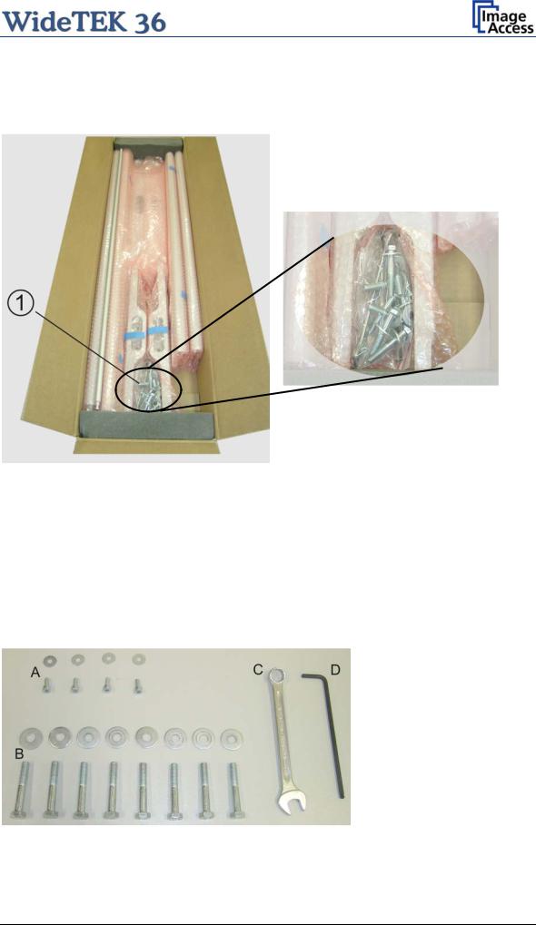
A.1.1 Contents of Floor Stand Box
The cardboard box of the floor stand contains all screws and washers, as well as the tools to assemble the floor stand, in a separate plastic bag.
Picture 2: Floor stand box opened |
Picture 3: Assembling material |
1:Plastic bag with assembly material
The plastic bag contains all screws, washers and tools to assemble the floor stand.
A.1.1.1 List of Assembling Material and Tools
A4x screws DIN 912 M5x10
4x washer DIN 9021 – 5.3
C Combination wrench, size 13
D Allen wrench size 4
B8x screws ISO 4016 – M8x50x22-WS
8x washer DIN 9021 – 8.4
Setup and Assembly Manual |
Page 15 |
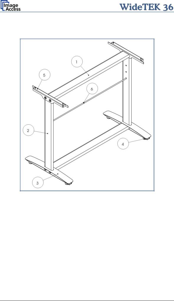
A.1.2 Floor Stand Overview
The engineering drawing below shows all major elements of the floor stand.
|
|
Picture 4: Technical drawing of floor stand |
The floor stand is built out of five different components and one round rod. |
||
|
|
|
No |
Qty |
Description |
1 |
2 |
Horizontal traverse. This part is used on the top as well as on the bottom. |
|
|
|
2 |
2 |
Vertical leg. This part is used on the left as well as on the right side. |
|
|
|
3 |
2 |
Foot bracket. This preassembled part is used on the left and right side. |
|
|
|
4 |
4 |
Adjustable feet. These are preassembled to the foot bracket. |
|
|
|
5 |
2 |
Top bracket: This part is used on the left and right top side. |
|
|
|
6 |
1 |
Horizontal rod. This part supports the paper exit basket. |
|
|
|
Page 16 |
Setup and Assembly Manual |

A.1.3 Parts of Floor Stand
Take all parts out of the box and place them as shown below and check for possible damages.
Picture 5: Floor stand components
The numbers in the picture above correspond to the numbers in the technical drawing.
Setup and Assembly Manual |
Page 17 |

A.2 Assembling the Floor Stand
Start with the foot profile (component #3), the side pillar (component #2), and the traverse (component #1).
Note: The three boreholes on the vertical leg (part #2) that are only on one side must face to the inner side of the floor stand. They should also be in the upper part of the leg. The technical drawing illustrates the correct position.
First insert a vertical leg into a foot bracket. The brackets have a cutout for the traverse. The foot brackets are designed symmetrically, therefore either one fits left and right.
Picture 6: Side pillar in foot profile
Next, insert the traverse as shown in the picture below.
Picture 7: Traverse inserted into foot bracket
Page 18 |
Setup and Assembly Manual |

Fasten the three components with two screws ISO 4016 – M8x50x22-WS. Place a washer on each screw.
Picture 8: Inserting screws with washer
Tighten the screws with the combination wrench, size 13, which comes with the floor stand.
Note: All screws should only be hand-tightened at first. The components should have a little play until all parts are assembled.
Repeat the steps described above with the second foot bracket and the second vertical leg.
Upon completion, the floor stand should look as shown in the picture below.
Picture 9: Bottom and side components assembled
Setup and Assembly Manual |
Page 19 |

Place the top brackets on the vertical legs. The oval cut-out must face to the inner side.
Picture 10: Top bracket on vertical leg
Insert the second traverse between the side legs.
Picture 11: Upper traverse inserted
Assemble the traverse, the top brackets and the legs with two ISO 4016 – M8x50x22-WS screws and a washer on each side.
Tighten all screws on the floor stand with the combination wrench, size 13.
Page 20 |
Setup and Assembly Manual |

Finally, insert the rod between the side legs. This rod supports the paper output tray. It has three positions for varying tray positions.
Picture 12: Inserting the rod
A.3 Combining Floor Stand and Scanner
After assembling the floor stand, the WideTEK 36 scanner can easily be placed on it in a safe position.
Note: For safety reasons, the scanner should be handled by two persons.
The transport box has notches at each corner in order to lift the scanner easily out of the box.
Picture 13: Two persons lifting the scanner out of the transport box
Setup and Assembly Manual |
Page 21 |
Loading...