

Page 1
Operation Manual
Page 2

File:
WT36C_WT48C_OperationManual-D2.docx
Page 3

2010 – 2015 by Image Access GmbH, Wuppertal, Germany.
Printed in Germany.
Reproduction in whole or in part in any form or medium without express written permission of
Ima
Scan2Net
All other trademarks are the property
Image Access reserves the right to change the described products, the specifications or
documents at any time without prior notice.
For the most recent version, always check our web site
or
www.imageaccess.us or the customer service portal at portal.imageaccess.de
All rights reserved.
ge Access is prohibited.
®
, WideTEK® and Bookeye® are registered trademarks of Image Access.
of their respective owners.
www.imageaccess.de
Manual Page 3
Page 4

Introduction
Dear Customer,
The Image Access team congratulates you on the acquisition of this innovative large
format scanner.
We at I mag e Access are proud of the work we do; it is the result of our extremely high
standards of production and stringent quality control.
®
With the WideTEK
which covers a wide scope of applications due to its versatility. Its integrated web
based user interface makes all functions available in structured menus.
36C / WideTEK® 48C, Image Access offers an efficient scanner
This operation manual is designed to lead you through all situations which will arise
when using the WideTEK
®
36C / WideTEK® 48C.
For this reason, we ask you to read the manual at tentively before starting to work with
the sanner. By doing so, you will avoid operation errors and you can control all
functions from the beginning.
In addition please consider the following points:
• Damages to your unit may have occurred during shipping. Please check for
damages immediately after delivery of the unit. Inform your supplier if damage
has occurred.
• Read and ensure that you understand the safety notes. They were developed
for your protection and safety as well as to protect the unit.
• Regular maintenance conserves the high quality and safety of the
®
WideTEK
36C / WideTEK® 48C during the entire service life.
If you have any further questions, please feel free to contact your local dealer or
Image Access, Inc. directly. Our staff will be happy to help you.
®
For your daily work with the WideTEK
36C / WideTEK® 48C scanner, we wish you
success and complete satisfaction.
Regards
Your Image Access Team
Page 4 Manual
Page 5

About this Manual
Operation Manual
The Operation Manual gives all information about the normal operation and behavior
of the device. It is written for people who only operate the device and do not perform
setup and adjustment procedures. All device elements and software functions are
described in detail, although some of them might never be used. This manual does not
cover any application software. Refer to the appropriate application software manual to
learn about the application software.
Setup Manual
The Set up Manual is writ ten f or technical staff with some basic mechanical as well as
software skills. Many r esellers will offer on-site installation; therefore, large parts or all
of the setup and assembly manual might not be of interest to the reader. The access
level at which the setup and adjustment processes are performed is called “Power
user”. This “Power user” level is password protected from access by the normal
operator.
All available manuals for this device can be downloaded from our customer service
portal at http://portal.imageaccess.de
. Be sure to always check for the latest versions of
these manuals.
This manual is divided into the sections A to E.
Section A describes the hardware of the device and gives an overview of all
components and connectors of the scanner. Remember that t his device
is a precise optical instrument and should be handled accordingly.
Note: Optional the WideTEK® 36C can be delivered with an appropriate floor
®
stand. It is recommended to always use the WideTEK
36C in
combination with the floor stand.
Section B describes the functions of the touchscreen and how to operate the
scanner with the touchscreen.
Section C gives a short introduction and basic information about the new user
interface ScanWizard. All details about the interface can be found in the
integrated “Help” texts in the scanner.
Section D informs about the setup levels in general and descr ibes the access level
User in detail.
Section E describes test and troubleshooting procedures.
Section F contains all technical data of the scanner and the manufacturer
declarations concerning safety and electromagnetic compatibility (EMC).
Manual Page 5
Page 6

Version
Published in
Content/Changes/Supplements
A2
July 2011
Information after EMC and safety testing and certification added.
renumbered to
Content of chapter C.5.2 revised, new screenshots added.
A4
October 2011
Chapter B.6.3.1 added. In Chapter C.3.3 additional information
Chapter C.3.7.2
FCC note added in chapter E.6.
A5
December 2011
Update Technical Data
B
April 2012
Update of content of User Settings (FW Vers. 5.71).
New structure in chapter C.3.5 and its subfolder.
New screen screenshots of some kiosk application screens.
B2
June 2013
Section D describes now the “ Setup Le vel”. Form er chapter D and
E have been renumbered.
Section C: Content change because of introduction of the new
user interface ScanWizard.
D
April 2014
Combination of the
/
operation
Chapter B.1.1, chapter D.1.3.2, chapter D.1.3.4 added.
D2
September 2014
Chapter C.1.1 and C.1.1 added. Table in chapter E.1 modified.
EMC information according to the standard EN 55022
equipment in a residential area is likely to
cause harmful interference in which case the user will be required to correct the
Version History
A May 2011 Preliminary version.
A3 September 2011 Chapter C.3. 9: New content, former chapt er C.3.9
C.3.10.
about “Container” format for multipage output.
added.
B1 March 2013 Valid with firmware 5.8.
Copyright note with updated trademark information.
The new WideTEK
New: Chapter B.5.1. Zonal OCR
Previous chapter B.5.1 and all following chapters renumbered.
®
36C logo has been intro duc ed .
C December 2013
Warning!
WideTEK® 36C
manuals in one manual.
Differences between the scanner models will be highlighted.
Chapter B.3.2, B.3.3, B.3.5 and B.3.6 with ne w conte nt .
WideTEK® 48C
This is a class A device. Operation of these
interference at his own expense.
Page 6 Manual
Page 7

Table of Content
Introduction -------------------------------------------------------------------------- 4
About this Manual ----------------------------------------------------------------- 5
Version History --------------------------------------------------------------------- 6
A Hardware ----------------------------------------------------------------------- 14
A.1 Safety Notes ...................................................................................................... 14
A.1.1 Marking of Safety Notes 14
A.2 Certification ........................................................................................................ 14
A.3 General Notice ................................................................................................... 14
A.4 Safety Precautions ............................................................................................. 15
A.5 Device Location.................................................................................................. 16
A.6 Maintenance ...................................................................................................... 17
A.6.1 Touchscreen 17
A.6.2 Surfaces 17
A.6.3 Glass plates 17
A.7 Repair ................................................................................................................ 17
A.8 Content on Delivery ............................................................................................ 18
A.8.1 WideTEK® 36C 18
A.8.2 WideTEK® 48C 20
A.8.3 Keeping the Transport Box for later use 21
A.9 Device Overview ................................................................................................ 22
A.9.1 WideTEK® 36C – Front Side Elements 22
A.9.2 WideTEK® 36C – Back Side Elements 22
A.9.3 WideTEK® 48C – Front Side Elements 23
A.9.4 WideTEK® 48C – Back Side Elements 23
A.9.5 Monitor Connector WideTEK® 36C 24
A.9.6 Monitor Connector WideTEK® 48C 24
A.9.7 Recovery Key Connector 25
A.10 Connect ing t o the Power Source ........................................................................ 26
A.10.1 Powering up the Scanner 27
A.10.2 Starting the Scanner from Standby Mode 27
A.10.3 Switching the Scanner to Standb y Mode 27
A.10.4 The Help Function 27
Manual Page 7
Page 8

Table of Content, part 2
B Touchscreen Oper a t ion --------------------------------------------------- 28
B.1 Select Application .............................................................................................. 28
B.1.1 Document Transport Window 29
B.2 The Kiosk User Interface ................................................................................... 30
B.2.1 Control Fields of the Touchscreen 31
B.3 Touchscreen – Document Source ...................................................................... 32
B.3.1 DPI 32
B.3.2 Transport Speed 33
B.3.3 Exposure 34
B.3.4 Format 35
B.3.4.1 Maximum 35
B.3.4.2 Auto 36
B.3.4.3 Crop and Deskew 36
B.3.4.4 DIN 37
B.3.4.5 ANSI 37
B.3.5 Scan Mode 38
B.3.6 Auto Density 39
B.4 Touchscreen – Image Quality ............................................................................ 40
B.4.1 Color Mode 41
B.4.2 File Format 41
B.4.2.1 JPEG 41
B.4.2.2 TIFF 42
B.4.2.3 PNM 42
B.4.2.4 PDF 42
B.4.3 Brightness 43
B.4.4 Contrast 43
B.4.5 Image Sharpness 43
B.4.6 Image Rotation 44
B.4.7 Mirror 44
B.4.8 Invert 44
B.4.9 Despeckle 44
Page 8 Manual
Page 9

Table of Content, part 3
B.5 Touchscreen – Viewer&Job Control ................................................................... 45
B.5.1 Zonal OCR 47
B.5.2 Job Mode 50
B.5.2.1 Navigating through the list of images 52
B.5.2.2 Moving an image to another position 53
B.5.2.3 Adding an image at an any position to the list 53
B.5.2.4 Deleting an image from the list 53
B.5.2.5 Rescan an image 53
B.5.2.6 Finalizing the Job mode 54
B.5.2.6.1 Job mode time out 54
B.6 Touchscreen – Send To ..................................................................................... 55
B.6.1 Changing a file name or other entries 56
B.6.2 USB Options 57
B.6.2.1 List of suitable USB storage media 57
B.6.3 Copy Options 58
B.6.3.1 Printer Settings 58
B.6.4 FTP Options 59
B.6.5 Network Options 60
B.6.6 Mail Options 61
B.6.6.1 Transaction modes 62
C Software Operation --------------------------------------------------------- 63
C.1 The ScanWizard User Interface ......................................................................... 64
C.1.1 Online Help 65
C.1.2 Exit ScanW izard 65
C.2 Information ......................................................................................................... 66
D The Setup Level -------------------------------------------------------------- 67
D.1 Access Level User ............................................................................................. 68
D.1.1 Device Info Screen 69
D.1.2 Operation Info Screen 71
D.1.3 User Settings Screen 72
D.1.3.1 Language Selector 73
D.1.3.2 File Name 74
D.1.3.3 Power Saving 75
D.1.3.4 Transport Speed 76
D.1.3.5 Volume 77
D.1.3.6 Splitting Start Page 78
Manual Page 9
Page 10

Table of Content, part 4
E Tests and Troubleshooting ---------------------------------------------- 79
E.1 T r oubleshooting Matrix ...................................................................................... 79
F Technical Data ---------------------------------------------------------------- 80
F.1 Scanner Specifications ...................................................................................... 80
F.2 Electrical Specifications ..................................................................................... 82
F.3 Ambient Conditions ............................................................................................ 83
F.4 Dimensions and Weight ..................................................................................... 83
F.5 CE Declarat io n of Conformity ............................................................................ 84
F.6 FCC Declaration of Conformity .......................................................................... 86
Page 10 Manual
Page 11

Table of Pictures
Picture 1: Minimum distances to the scanner ...................................................................16
Picture 2: Transport box opened ......................................................................................18
Picture 3: Parts in the transport box .................................................................................19
Picture 4: Wooden frame remove.....................................................................................19
Picture 5: Content of transport box with WT48C-300-BDL ...............................................20
Picture 6: Transport box elements ready to store .............................................................21
Picture 7: WideTEK 36C front view ..................................................................................22
Picture 8: WideTEK 36C Main power switch and connectors ...........................................22
Picture 9: WideTEK 48C front view ..................................................................................23
Picture 10: WideTEK 48C Main power switch and connectors .........................................23
Picture 11: WideTEK 36C DVI connector .........................................................................24
Picture 12: WideTEK 48C DVI connector .........................................................................24
Picture 13: Recovery Key connector, covered with plastic cap .........................................25
Picture 14: Start screen after start-up ..............................................................................28
Picture 15: Document Transport ......................................................................................29
Picture 16: Viewer & Job Control screen ..........................................................................30
Picture 17: Document Source screen ...............................................................................32
Picture 18: List of Resolutions ..........................................................................................32
Picture 19: Available Scan Modes....................................................................................33
Picture 20: Exposure Modes ............................................................................................34
Picture 21: Numeric key pad to set threshold value .........................................................34
Picture 22: Selector for Format settings ...........................................................................35
Picture 23: Format mode Maximum .................................................................................35
Picture 24: Format mode Auto .........................................................................................36
Picture 25: Format mode Crop and Deskew ....................................................................36
Picture 26: Format mode DIN ..........................................................................................37
Picture 27: Format mode ANSI ........................................................................................37
Picture 28: Scan Mode selector .......................................................................................38
Picture 29: Auto Density controller ...................................................................................39
Picture 30: Image Quality, screen 1 .................................................................................40
Manual Page 11
Page 12

Table of Pictures, part 2
Picture 31: Image Quality 2 ............................................................................................. 40
Picture 32: List of Color Modes ........................................................................................ 41
Picture 33: Submenu File Format “jpeg” .......................................................................... 41
Picture 34: Submenu File Format TIFF ............................................................................ 42
Picture 35: Brightness slider ............................................................................................ 43
Picture 36: Contrast slider ............................................................................................... 43
Picture 37: Image Sharpness .......................................................................................... 43
Picture 38: Image Rotation .............................................................................................. 44
Picture 39: Mirror ............................................................................................................. 44
Picture 40: Invert ............................................................................................................. 44
Picture 41: Despeckle ..................................................................................................... 44
Picture 42: Viewer & Job Control screen ......................................................................... 45
Picture 43: Scanned image in preview area ..................................................................... 45
Picture 44: OCR button activated .................................................................................... 47
Picture 45: OCR touchscreen .......................................................................................... 47
Picture 46: Rectangle defines the area for OCR function ................................................. 48
Picture 47: Pre-selection area selected ........................................................................... 48
Picture 48: Selected area magnified ................................................................................ 49
Picture 49: OCR result..................................................................................................... 49
Picture 50: Bottom line with status ................................................................................... 50
Picture 51: TFT flat screen after selecting “Job mode”..................................................... 50
Picture 52: Disclaimer when staring the Job mode .......................................................... 51
Picture 53: Job mode start screen ................................................................................... 51
Picture 54: Controller circles blanked out ........................................................................ 52
Picture 55: Destination to finalize Job mode .................................................................... 54
Picture 56: Information when time out ends ..................................................................... 54
Picture 57: "Send To" screen #1 ...................................................................................... 55
Picture 58: "Send To" screen #2 ...................................................................................... 55
Picture 59: Alphanumeric keyboard ................................................................................. 56
Picture 60: Directory of connected USB data carrier ........................................................ 57
Page 12 Manual
Page 13

Table of Pictures, part 3
Picture 61: Parameters of Copy Options ..........................................................................58
Picture 62: Printer settings window ..................................................................................58
Picture 63: Parameters of FTP Options............................................................................59
Picture 64: Parameters of Network Options .....................................................................60
Picture 65: Parameters of Mail Options ............................................................................61
Picture 66: Interactive mode, mail options ........................................................................62
Picture 67: Scan2Net® main menu ..................................................................................63
Picture 68: ScanWizard interface .....................................................................................64
Picture 69: ScanWizard interface layout...........................................................................64
Picture 70: Online Help ....................................................................................................65
Picture 71: “Exit” returns to Scan2Net® main menu .........................................................65
Picture 72: Summary of device parameters .....................................................................66
Picture 73: Login screen ..................................................................................................67
Picture 74: User screen ...................................................................................................68
Picture 75: Device Info screen .........................................................................................69
Picture 76: Firmware information .....................................................................................70
Picture 77: Operation Info screen ....................................................................................71
Picture 78: Start screen User Settings .............................................................................72
Picture 79: Language Selector of the setup menu ............................................................73
Picture 80: List of languages ............................................................................................73
Picture 81: Filename ........................................................................................................74
Picture 82: List of wildcard characters ..............................................................................74
Picture 83: List of power down times ................................................................................75
Picture 84: Transport speeds ...........................................................................................76
Picture 85: Volume level ..................................................................................................77
Picture 86: Splitting Start Page ........................................................................................78
Manual Page 13
Page 14

A Hardware
A.1 Safety Notes
Read and ensure that you understand the safety notes.
They are designed for your protection and for your safety.
Follow all safety notes to avoid damage to the device.
A.1.1 Marking of Saf e ty Notes
All safety notes are marked with a yellow triangle warning sign.
Next to the warning sign, you’ll find a description of the danger.
Safety Note!
Example text.
A.2 Certification
The WideTEK® 36C / WideTEK® 48C scanners fulfill all requirements of the following
standards:
IEC 60950-1, International Safety Standard for Information Technology Equipment
UL 60950-1, Safety for Information Technology Equipment (US standard)
CAN/CSA C22.2 No.60950-1, Safety for Information Technology Equipment
(Standard for Canada)
EN 60950-1, Safety for Information Technology Equipment (European standard)
A.3 General Notice
This manual describes the functions of a complete equipped scanner. If your device is not
equipped with all features, deviations are possible.
Because of the identical content of the touchscreen menus and ScanWizard menus, the
pictures are valid for both scanner versions.
Page 14 Manual
Page 15

this device to rain
A.4 Safety Precautions
Warning: Please read all the safety precautions before you operat e the scanner. Serious
injury can occur to you or to others if you do not know how to use it safely.
To prevent fire or shock hazard, do not expose
or any type of moisture.
Follow all safety precautions to avoid personal injury or damage to the device.
1. Place the scanner in a clean, well-ventilated room. Do not operate the scanner in an
area with poor ventilation.
2. Openings in the scanner’s housing in the front or at the back are provided for air
circulation. Do not cover or block the openings.
3. Do not place the scanner near a heat or cold emitting source such as a space heater,
furnace, or air conditioning unit.
4. Do not place the scanner near any devices or electrical boxes emitting high voltage.
5. Always place the scanner on a stable surface.
6. Do not lean on the scanner.
7. Do not place cups containing liquids or other such objects on top of the scanner or on
the scanner table. If liquid spills into the scanner it can cause damage. If this occ urs,
turn the scanner off, unplug the power cord from the wall receptacle and contact the
Image Access Technical Support.
8. Do not put any objects into any scanner housing openings unless specifically
instructed to do so by Image Access Technical Support.
9. Do not disassemble the scanner. If there is a need to disassemble the scanner,
please contact the Image Access Technical Support.
10. Do not use the scanner if it has been physically damaged. If this occurs, turn the
scanner off, unplug the external power supply and contact the Image Access
Technical Support.
11. The scanner should be used only with the external power supply that is supplied with
the scanner. If you are unsure, please contact the Image Access Technical Support.
12. Always turn the power off and unplug the external power supply before cleaning the
scanner.
13. When cleaning, only use Image Access-approved cleaners. Do not use any type of
solutions, abrasives, or acids such as acetone, benzene, kerosene, mineral spirits,
ammonia, or nitric acid. Do not use any cleaners that contain these chemicals.
14. Use a dry or damp lint free cloth for cleaning the scanner.
15. Do not spray any liquids directly onto the scanner. Spray cleaning f luids directly onto
the cleaning cloth and use the cloth to clean the scanner.
Manual Page 15
Page 16
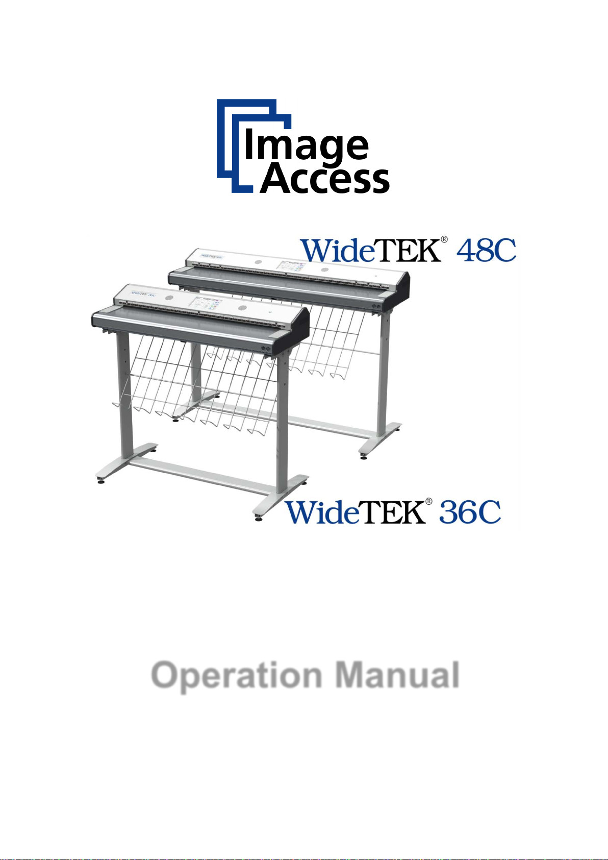
A.5 Device Location
The installation location must have
— a minimum distance of not less than 150 mm (6 inch) between the sides of the
scanner and the wall,
— a minimum distance of not less than 300 mm (12 inch) between the backside of the
scanner and the wall,
— a minimum distance of not less than one meter (3 feet) from any door or entrance
way and the scanner.
Use illustration below as a guide.
Picture 1: Minimum distances to the scanner
Do not operate the scanner in an area that has poor air circulation, and/or that is nonventilated.
Place the scanner on a flat and solid base. The load bearing capacity of the base must
correspond to the device weight.
It is recommended to place the scanner always on the floor stand which comes with the
scanner. The floor stand gives the best ergonomic position when using the scanner.
Choose a location that complies with the limits of temperature and humidity. Refer to the
technical specification, chapter F.3.
Note: Before using the WideTEK® 36C / WideTEK® 48C scanner in the new
environment allow at least one hour for temperature adaptation.
Temperature adaptation means:
A fast change from cold to warm environmental conditions can build up
condensation inside the housing. This will result in unfavorable scanned images
and could cause permanent damages to the unit.
Page 16 Manual
Page 17

A.6 Maintenance
Important: Ensure that no liquids will penetrate into the device housing.
A.6.1 Touchscreen
Before cleaning the touchscreen, switch the WideTEK® 36C / WideTEK® 48C off and
set the main power switch to position 0.
The touchscreen can be cleaned with a micro fiber cloth.
A.6.2 Surfaces
Use a soft, dampened cloth to clean the housing of the scanner. Recommended is a micro
fiber cloth.
A.6.3 Glass plates
Important: Do not use any cleanser with solvents to clean the glass plates!
The glass plates of the WideTEK® 36C / WideTEK® 48C have a special surface
coating.
It is recommended to clean the glass plates always with a micro fiber cloth.
Dampen the micro fiber cloth slightly before cleaning.
Clean the glass plate with minimum pressure. Do not rub the glass plate on isolated
positions.
After cleaning dry the glass plate with a soft cloth – micro fiber cloth recommended.
A.7 Repair
Note: There are not any parts or components of the WideTEK® 36C /
WideTEK® 48C scanner which can be repaired by the user.
All repairs and service works should be done by a trained technician only.
Manual Page 17
Page 18
WideTEK® 36C
E:
P1060754_a.jpg
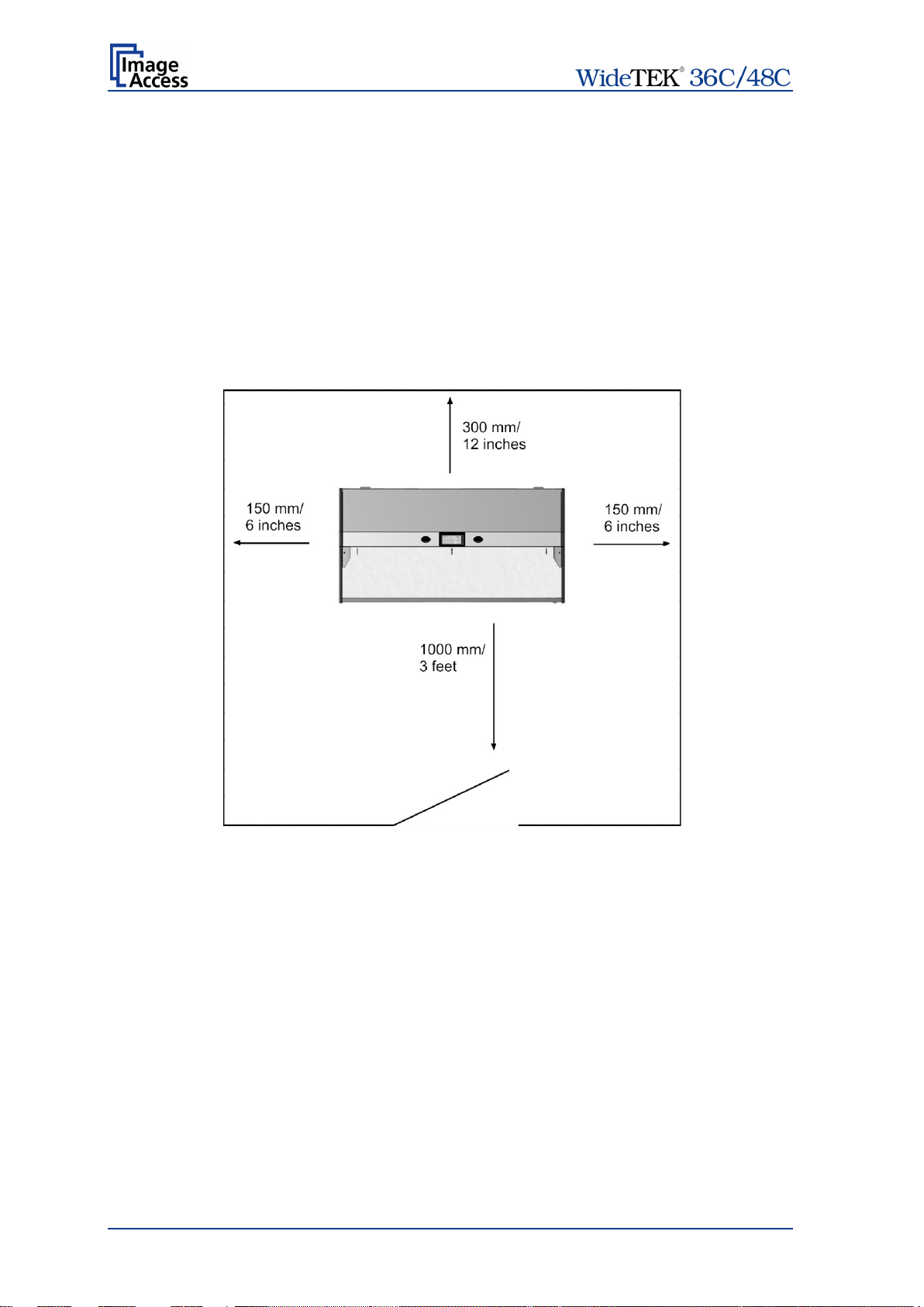
1: Paper output tray
A.8 Content on Delivery
A.8.1
When delivered, the scanner is placed at a Euro pallet, bordered at all sides by a stable
wooden frame and covered with a wooden top cover.
After removing the top cover of the transport box the paper output tray is visible.
\Bild\WT_36C\Verpackung\2011_03\
P1060755_c.jpg
Picture 2: Transport box opened
The WideTEK® 36C scanner as well as the cardboard box of the floor stand is held in the
transport box with a total of six foam inserts.
Remove the paper output tray and the foam mat to get access to the next parts.
Page 18 Manual
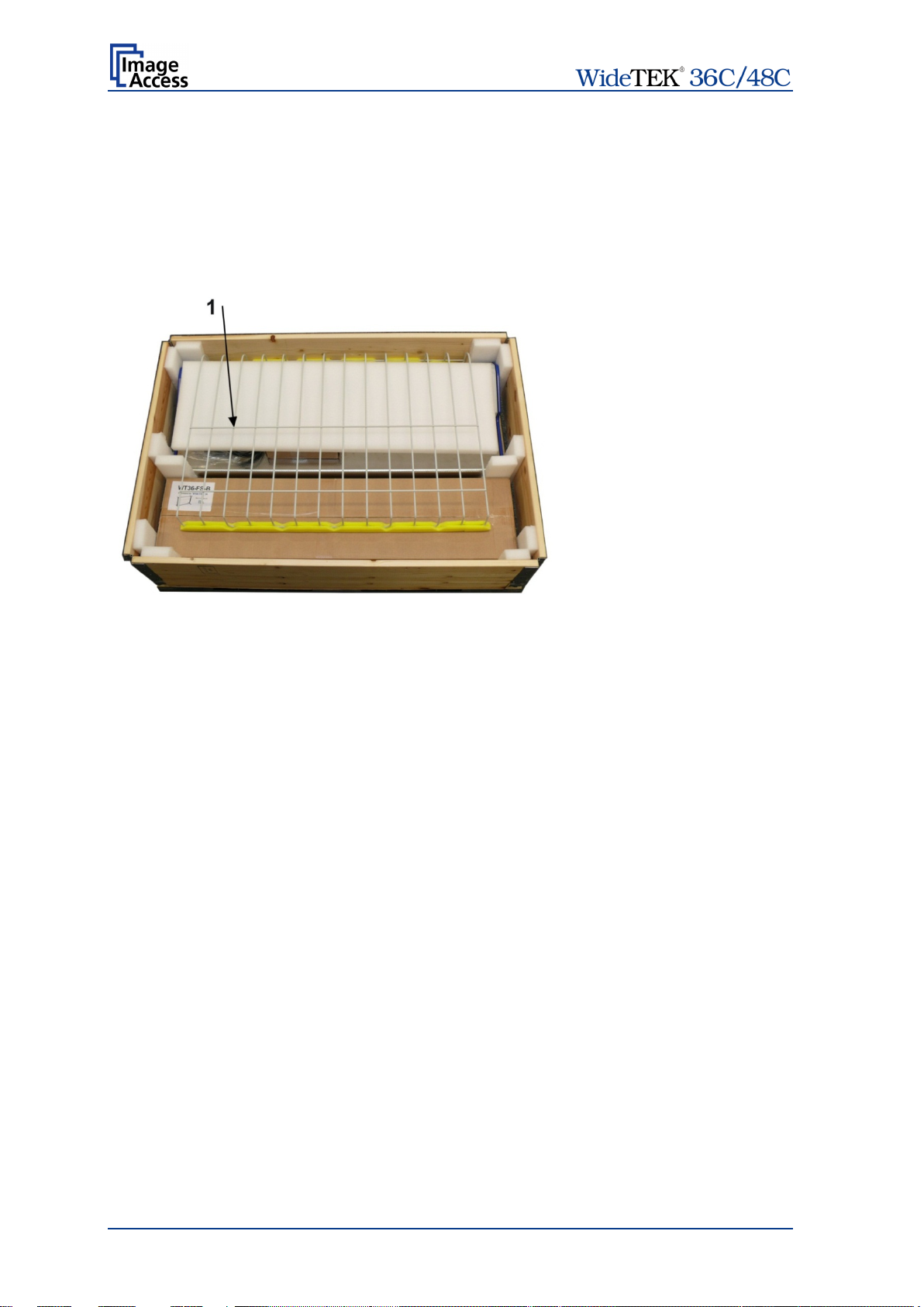
Page 19
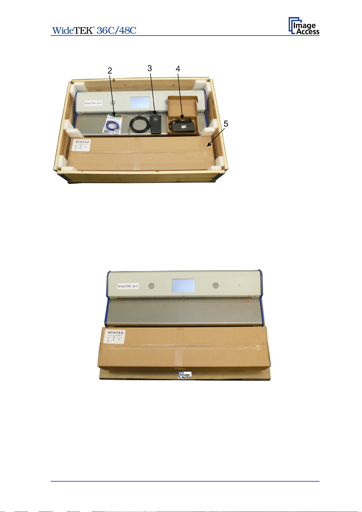
2: Patch cable
External power supply
with power connector
Floor stand in cardboard
Picture 3: Parts in the transport box
Take the three parts out of the transport box.
3: Foot pedal switch
4:
cable
5:
box
Remove the six foam inserts beside the scanner and the cardboard box.
The wooden frame will slide down when removing the foam inserts.
Lift the wooden frame to get access to the scanner and to the floor stand cardboard box.
Picture 4: Wooden frame remove
Manual Page 19
Page 20

WideTEK® 48C
A.8.2
When delivered, the scanner is placed at a Euro pallet, bordered at all sides by a stable
wooden frame and covered with a wooden top cover.
After removing the transport box top cover the scanner and all accessories are visible.
®
The WideTEK
48C scanner and all other components are held in the transport box with
foam inserts in the corners and at the long sides.
Picture 5: Content of transport box with WT48C-300-BDL
1: Accessory box with external power supply, patch cable and foot pedal.
2: Paper output tray. (Optional. Contained in bundle WT48C-300 BDL)
3: Monitor arm for external monitor. (Optional. Contained in bundle WT48C-300 BDL)
4: External 19” monitor. (Optional. Contained in bundle WT48C-300 BDL)
5: Reference folder with test targets, e.g. CSTT- and IT8 test target.
6: Operation manual.
7: Two sets of document return guides.
8: White reference test target
9: Floor stand. (Optional. Contained in bundle WT48C-300 BDL)
Page 20 Manual
Page 21

Take the parts out of the transport box.
WT48C-300: The box with floor stand is replaced by an empty box.
WT48C-300-BDL: Start with paper the output tr ay, then take out all boxes, the ref erence
folder and the all small accessories.
Pull up the foam inserts and remove them. Sometimes a little strength is necessary.
The wooden frame can be lifted after removing the foam insert s. Remove it to get access
to the scanner and to the floor stand cardboard box.
Note: High scanner weight. Lift the scanner with two persons from the pallet.
A.8.3 Keeping the Transport Box for later use
All elements used with the transport box can easily be stored.
The wooden frame can be folded. The foam inserts can be placed between the base plate
and the cover plate.
The wooden frame can be place on top of the cover plate.
Picture 6: Transport box elements ready to store
Manual Page 21
Page 22
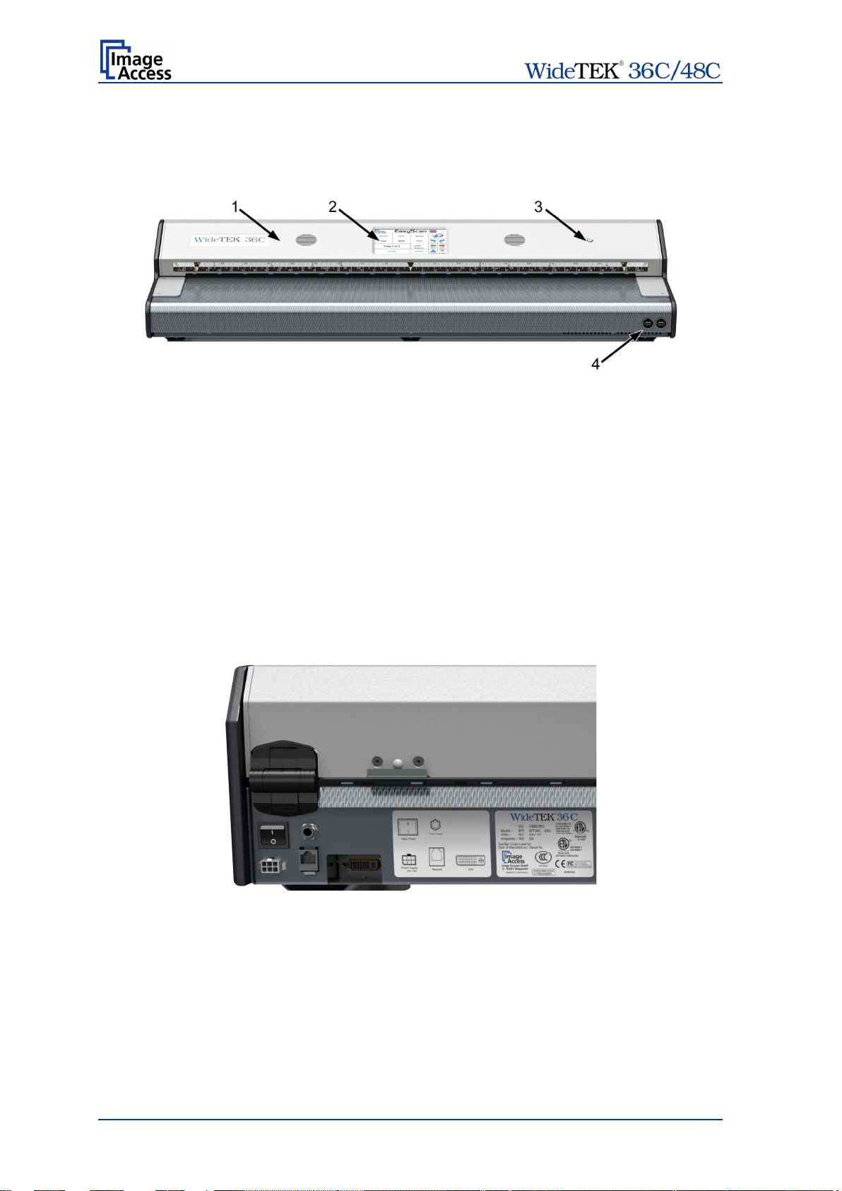
WideTEK® 36C
WideTEK® 36C
A.9 Device Overview
A.9.1
The main components of the WideTEK® 36C are:
1: Upper unit. The upper unit contains the cameras and the paper transport.
2: Touchscreen. The touchscreen shows all menus to set up and control the scanner
3: On/Off button. This button is used to power up the scanner from standby mode and
4: USB connectors. Enable the user to connect qualified USB storage media to the
to power down the scanner to standby mode.
scanner.
– Front Side Elements
Picture 7: WideTEK 36C front view
A.9.2
Seen from the operators view (i.e. from the front of the scanner), the connectors are
positioned at the right back side of the housing.
A label beside the connectors shows and names each connector.
Picture 8: WideTEK 36C Main power switch and connectors
– Back Side Elements
Page 22 Manual
Page 23
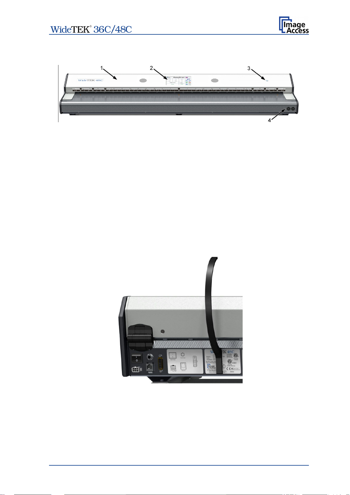
WideTEK® 48C
WideTEK® 48C
A.9.3
The main components of the WideTEK
1: Upper unit. The upper unit contains the cameras and the paper transport.
2: Touchscreen. The touchscreen shows all menus to set up and control the scanner
3: On/Off button. This button is used to power up the scanner from standby mode and to
power down the scanner to standby mode.
4: USB connectors. Enable the user to connect qualified USB storage media to the
scanner.
Picture 9: WideTEK 48C front view
– Front Side Elements
®
48C are:
A.9.4
Seen from the operators view (i.e. from the front of the scanner), the connectors are
positioned at the right back side of the housing.
Picture 10: WideTEK 48C Main power switch and connectors
– Back Side Elements
A label beside the connectors shows and names each connector.
Manual Page 23
Page 24
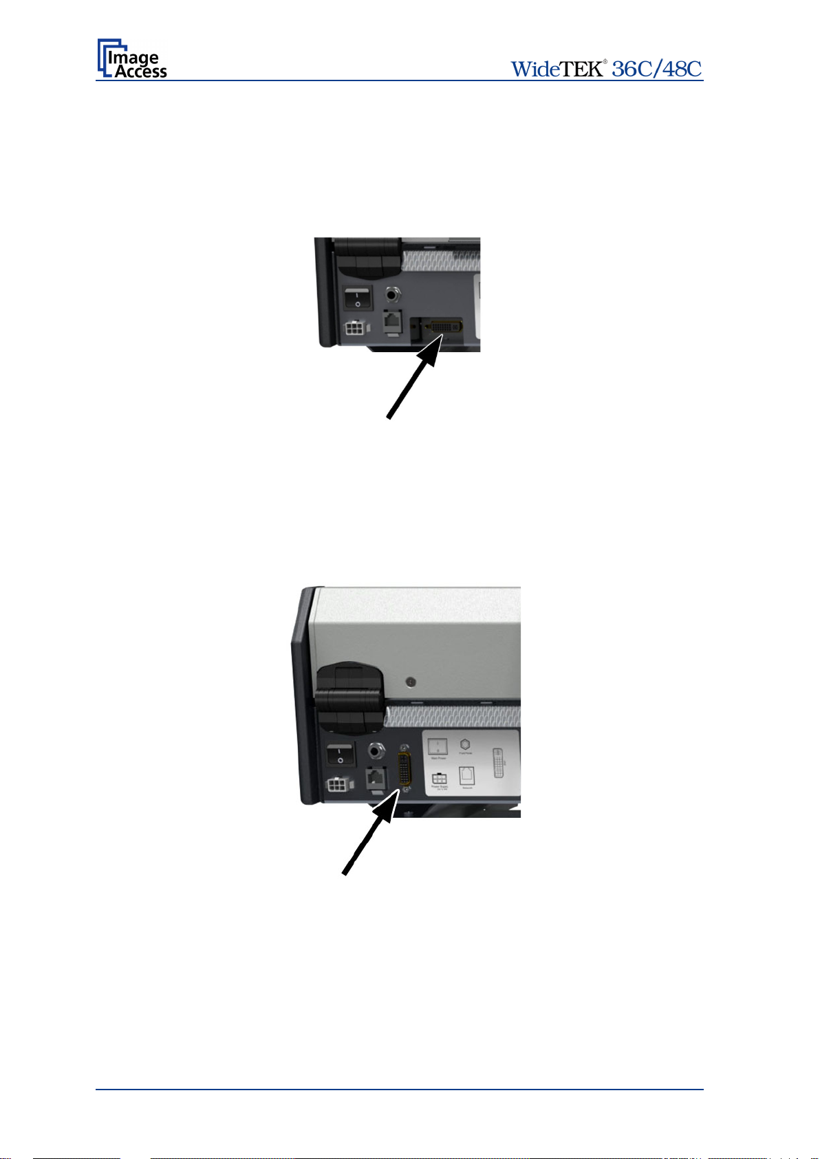
WideTEK® 36C
WideTEK® 48C
Note:
Although the scanners receptacle will accept DVI-D, DVI-A and DVI-I
A.9.5 Monitor Connec t or
To show previews of the scanned documents an external monitor c an be connected to the
WideTEK
A DVI video connectors allows connecting the monitor to the scanner.
®
36C.
Picture 11: WideTEK 36C DVI connector
A.9.6 Monitor Connec t or
To show previews of the scanned documents an external monitor c an be connected to the
WideTEK
®
48C.
A DVI video connector allows connecting the monitor to the scanner.
Picture 12: WideTEK 48C DVI conn ect or
Valid for both
scanner types
plugs, it only supports DVI-D.
DVI-I to VGA cables will not work on this connector.
Page 24 Manual
Page 25

A.9.7 Recover y Key Connect or
Seen from the operators view (i.e. from the front of the scanner), the Recovery Key
connector is positioned at the left back side of the housing.
Picture 13: Recovery Key connector, covered with plastic cap
Detailed information about the recovery function can be found in the separate
Setup Manual.
Please note: The recovery function should only be activated by an administrator!
Manual Page 25
Page 26

Ensure the electrical outlet is in perfect condition and that it is
Ensure that the electrical outlet is equipped with a fuse with the
The electrical outlet must be near this device and must be easily
A.10 Connecting to the Power Source
Before connecting the scanner to the external power supply and the power supply to the
electrical outlet, check the following items:
properly grounded.
proper capacity.
accessible.
Inspect the power cable and ensure that it is undamaged.
Use only the power cable delivered with the scanner.
Turn the device off before plugging or unplugging any cable.
The connector for the external power supply and the main power switch are both located
at the right side of the back of the document bed.
After the power source is connected and the main power s witch is turned on, the symbol
in the on/off button lights up.
Red illumination of the on/off button signals that the scanner is in standby mode.
Page 26 Manual
Page 27

Note:
Always turn off the scanner with the on/off button at the right side of
the scanner is disconnected from the
A.10.1 Powering up the Scanner
The main power switch is found at the back of the scanner.
Picture 8 resp. Picture 10 show the position of power supply connector and main power
switch.
After connecting the scanner to the external power supply, switch the main power switch
to position I. When the main power switch is in position I, the on/off button will be
illuminated and the scanner is in standby mode.
A.10.2 Starting the Scanner from Standby Mode
Push the red illuminated on/off button to start the scanner.
The button illumination changes to blue.
The scanner starts with self-test routines and verifies all system components. Status
messages will be displayed on the TFT flat screen (if connected) and on the touchscreen.
At the end of the start-up sequence, the touchscreen displays the start screen.
A.10.3 Switching the Scanner to Standby Mode
the front panel!
The main power switch should only be used when the scanner is in
stand-by mode and before
external power supply.
To turn off the scanner, press and hold the on/off button f or at least three seconds. While
pressing the button, a “click” sound is audible.
The content of the TFT flat screen and the touchscreen changes and display the
message: Going to shut down now …
Finally the TFT flat screen and the touchscreen switch off and the on/off button will be
illuminated red.
A.10.4 The Help Function
To support the user when working with the scanner, a help function is integrated into the
touchscreen menus. A Question Mark (?) symbol in the bottom lin e of the touchscreen
activates the help function.
After touching the question mark, an additional window opens in the touchscreen and
shows information about the menu items of the selected menu.
Touching the OK button will close the additional window.
Manual Page 27
Page 28

Touching this button will switch to a user programmable application.
a customized
Touching this button switches to the start screen of the integrated
and the corresponding subchapters
B Touchscreen Operation
The scanner can be controlled in two ways.
• Via the integrated touchscreen.
• Via a standard browser and the ScanWizard user interf ace. A shor t intr oduction of the
functions of the integrated ScanWizard user interface starts in chapter C.
Please note: All screenshots are taken from a fully equipped device with all options
and functions activated. Depending on the selected mode, the menus
displayed on the screen can vary.
GENERAL NOTICE
This manual describes the functions of a com plete eq uipped scanner. If your device is not
equipped with all features, deviations are possible.
B.1 Select Application
When the scanner starts from standby mode and finishes the startup procedure, the
touchscreen displays for approximately ten seconds the screen Select Application.
Picture 14: Start screen af ter start -up
This enables the user to operate the scanner with
application.
As factory default the EasyScan application is integrated.
To leave the application, the scanner must be restarted.
kiosk application.
Chapter B.2 to chapter B.6
describe the available functions.
Page 28 Manual
Page 29

Document Output
Eject: Transports the document out of the scanner after
Holds the document after terminating the scan
Scan Mode
Direct: Transports the document into the scanner until the
Transports the document into the scanner until the
photo sensor in the transport path detects the paper
Paper Feed Delay
0…5 [s] Defines the delay between inserting the document into
Tap this button to return to the start screen.
B.1.1 Document Tr a ns port Window
Touching this button opens the Document Transport window before
starting the Kiosk interface.
Picture 15: Document Transport
terminating the scan sequence.
Hold:
sequence at the output side of the transport path.
camera recognizes the document; then the document
returns to the start position.
Quick:
edge.
the transport path and transport start.
Manual Page 29
Page 30

B.2 The Kiosk User Interface
After touching the Scan2Net button the Viewer&Job Control screen is displayed on the
touchscreen.
Picture 16: Viewer & Job Control screen
The touchscreen is structured in four sections, which allow operators to control and select
various functions of the scanner.
1: This section shows the main controls or parameters depending on the selected
control field in section 2.
2: Control fields to select the menu screens directly.
3: This section shows the status of the scanner, e.g. “Ready to scan, allows starting
the scan sequence by touching Scan Now, allows returning to the start screen, and
displays date and time.
4: The content of this section changes dependent on the selected control field in
section 2. More specific information can be found in the respective chapters.
Note: To open the Document Transport windo w ( Picture 15) tap at the Scan2Net logo
in the upper right cor ner.
Page 30 Manual
Page 31

B.2.1 Control Fields of the Touchscreen
By touching the buttons in section 2 each menu screen can be reached directly.
The chapters B.3 to B.6 describe the functions of the menus in detail.
Touch this button to start the scan sequence.
Touch this button to return to the start screen from every other menu.
……
If available, this two arrow buttons switch to the next or to the previous menu screen.
Touch this button to return to the main menu.
Touch this button to set all parameters to default values.
Touching this button opens an additional window. The additional window contains short
information about the available functions.
Manual Page 31
Page 32

B.3 Touchscreen – Document Source
The number of buttons and controllers in each screen can vary depending on the selected
setup. The setup can be changed by the administrator in the Poweruser menu.
The Document Source screen allows selecting from a wide range of scan parameters.
Picture 17: Document Source screen
If the content of a screen is too large to be displayed in the touchscreen completely, a
scrollbar is displayed at the right side. Touch the scrollbar and move it to see all menu
items.
The content of some menus which open after touching can vary.
B.3.1 DPI
The Resolution setting allows selecting a resolution from a list of resolution values
supported by the scanner.
Picture 18: List of Resolutions
The list can be opened by touching the blue arrow symbol beside t he currently selected
value. Select a new resolution by touching the preferred value.
Page 32 Manual
Page 33

B.3.2 Transpor t S pe e d
The Transport Speed selector allows the user to select from two speed settings.
Picture 19: Available Scan Modes
This setting determines the transport speed when feeding a document into the scanner.
Normal Transports the document with default speed; recommended for most
documents.
Slow Transports the document with reduced speed; recommended for fragile
documents, e.g. old paper or very delicate material.
Manual Page 33
Page 34

Black Cut
Sets the threshold for black. All pixel values found in the image below
Auto
Sets the threshold for black and activates the automatic exposure
This function analyzes the image and detects the brightest and the
darkest area. The detected brightness range is expanded to the
maximum range of the scanner. Otherwise all values below the
B.3.3 Exposure
The Exposure screen allows selecting the functions Black Cut and Auto.
Fixed switches the function off.
Picture 20: Exposure Modes
When Black Cut or Auto is selected a numeric key pad opens.
Picture 21: Numeric key pad to set threshold value
0 (zero) to 100
the selected value are set to solid black.
Result: The image contrast is improved.
0 (zero) to 100
control.
threshold are defined as “black”.
Result: Automatic contrast control and the image contrast is improved.
To set a new value, touch in the line of the displayed value and erase the value with the
DEL button.
Enter the new value with the key pad and touch Send to send the new value.
Page 34 Manual
Page 35

B.3.4 Format
The Format button allows selecting the scan area size.
Depending on the Document Mode selected, the available formats will vary.
The bottom line of the button Format shows the current format setting.
Picture 22: Selector for Format settings
The following subchapters describe the available combinations of document mode and
format.
B.3.4.1 Maximum
Picture 23: Format mode Maximum
Landscape: Scans the maximum scan area in landscape orientation.
Portrait: Scans the maximum scan area in portrait orientation.
Manual Page 35
Page 36

B.3.4.2 Auto
The complete scan area will be scanned.
Picture 24: Format mode Auto
The resulting image will be reduced to the document size. If the document is not exactly
aligned horizontally, the resulting images will have the smallest possible black margin.
The black margin depends on the size of rectangle which covers the complete document.
B.3.4.3 Crop and Deskew
The complete scan area will be scanned.
Picture 25: Format mode Crop and Deskew
The resulting image shows the document aligned and cropped to its real size.
Page 36 Manual
Page 37

B.3.4.4 DIN
Picture 26: Format mode DIN
When selecting DIN, an additional small window opens.
It shows the available DIN (=ISO) document sizes as well as 25 inch and 36 inch width as
scan area dimension.
All formats are positioned symmetrically to the horizontal middle of the document input.
B.3.4.5 ANSI
Picture 27: Format mode ANSI
When selecting ANSI, an additional small window opens.
It shows the available ANSI document sizes as scan area dimension.
All formats are positioned symmetrically to the horizontal middle of the document input.
Manual Page 37
Page 38

B.3.5 Scan Mode
The Scan Mode selector allows the user to select between two scan quality settings.
Picture 28: Scan Mode selector
In general, the scan resolution has always an impact at the scan speed.
The higher the resolution, the lower the resulting scan speeds.
Fast Scans with normal scan speed, depending from the selected resolution.
High Quality Reduces the scan speed to the half.
Page 38 Manual
Page 39

B.3.6 Auto Densi ty
The Auto Density controller is used to set the scanner’s sensitivity for the automatic
format detection.
Default value: 60
Picture 29: Auto Density controller
When scanning dark documents, the value should be reduced in small steps until the
desired result is achieved.
In general: The higher the numeric value, the more contrast must be between
background and scanned document.
Manual Page 39
Page 40

B.4 Touchscreen – I mage Quality
The Image Quality screen allows setting a wide range of image quality parameters.
Picture 30: Image Quality, screen 1
In color mode Binary, the menu will be extended by two more menu items.
Picture 31: Image Quality 2
The additional menu items are Invert and Despeckle.
See chapter B.4.8 and B.4.9
Page 40 Manual
Page 41

B.4.1 Color Mode
By touching the selection arrow of the Color Mode section the list of available color
modes opens.
Picture 32: List of Color Modes
Touch the title of the desired color mode to select the mode. The list closes subsequently.
Picture 32 shows the available color modes.
B.4.2 File For m a t
Press the File Format button to select a file format for the images.
B.4.2.1 JPEG
Picture 33: Submenu File Format “jpeg”
Depending on the file format selected, some additional parameters will be displayed.
With the JPEG file format, a value for the image quality can be entered by the numeric
key pad.
This value determines the compromise between quality and compression rate. A higher
quality factor produces larger files. The default setting of 75 is a good compromise for
most documents.
Manual Page 41
Page 42

B.4.2.2 TIFF
Picture 34: Submenu File Format TIFF
With the TIFF file format, the compression method of the file can be selected with the
TIFF Compression buttons.
CCITT G4 Recommended with color mode “Binary”.
JPEG Recommended for all other color modes.
None Disables the data compression.
B.4.2.3 PNM
With the PNM file format, no additional parameters are available.
B.4.2.4 PDF
With the PDF file format, the same compression met hods are available as with the TIFF
format (see Picture 34).
Press this button to return from a submenu to the main menu.
Page 42 Manual
Page 43

B.4.3 Brightness
Picture 35: Brightness slider
The Brightness slider defines the resulting brightness in the image. Lower brightness
values result in darker images, higher values result in brighter images.
Values close to 0% or to 100% may result in unwanted artifacts.
Move the slider indicator to the desired position to set the value.
B.4.4 Contrast
Picture 36: Contrast slider
The Contrast slider defines the contrast in the image. Lower contrast values result in
“smoother” images, higher values show more details and the images become “crisper”.
Values close to 0% or to 100% may result in unwanted artifacts.
Move the slider indicator to the desired position to set the value.
B.4.5 Image Sharpness
Picture 37: Image Sharpn ess
The Image Sharpness slider invokes an advanced automatic sharpening algorithm which
sharpens the image before any other operation is performed.
The value “zero” disables the function. Very high values may produce artifacts depending
on the type of document.
Move the slider indicator to the desired position to set the value.
Manual Page 43
Page 44

B.4.6 Image Rot a ti on
Picture 38: Image Rotation
The value selected from the list defines the rotation of the image in a clockwise direction.
The image will be rotated directly after scanning and before display
B.4.7 Mirror
Picture 39: Mirror
This control mirrors the image along the selected mirror axis.
Using this setting can be helpful if scanning transparencies from the back.
B.4.8 Invert
Picture 40: Invert
This control is only available with the color modes Binary and Enhanced Halftone.
If set to on, the color of the resulting image will be inverted.
B.4.9 Despeckle
Picture 41: Despeckle
This control is only available with the color modes Binary and Enhanced Halftone.
Available modes are 4x4p and Off.
Page 44 Manual
Page 45

The ICC Profile checkbox is displayed when the resolution for the
scan mode is
(1)
B.5 Touchscreen – Viewer&Job Control
The Vi ewer Control screen allows the operator to control and modify the image on the
TFT flat screen.
Picture 42: Viewer & Job Control screen
The preview section (1) represents the TFT flat screen.
The scanned image is displayed on the TFT flat screen and with reduced quality in the
preview section right beside the controller elements.
Picture 43: Scanned image in preview area
scan is 300 dpi or higher or when the High Quality
active.
Manual Page 45
Page 46

The middle circle contains the keys to
scale the image to the real size of the source
document. A centered cutout of the image is
The controller is structured in three round elements (circles).
The outer circle contains the keys to move the zoomed area
across the image.
zoom in
zoom out
rotate the image in clockwise direction in steps
of 90 degrees
displayed on the TFT flat screen.
The inner circle symbol allows selecting between two
settings. It sho ws the selectable setting, not the selected
setting.
Touching this symbol displays the image with its genuine
dimensions (100%), depending on the resolution selected
for scanning.
Touching this symbol displays the complete image on the
TFT flat screen. The image will be scaled to a size that
matches the screen size.
Table 1: Controller circles and their functions
Page 46 Manual
Page 47

OC
B.5.1 Zonal OCR
The scanner offers a zonal OCR function. This function can be activated by the button
positioned right below the preview section.
Zonal OCR means, that only the marked area will be processed by the OCR function. Text
and line feed will be found only. A layout analysis will not be executed.
Prior using the zonal OCR it is required to set the scan parameters as follows:
Format: Crop and deskew
Resolution: Between 300 dpi and 600 dpi.
Note: With resolution higher than 600 dpi the OCR button will not be activated.
File format: PDF
Scan the document. The preview section of the touchscreen shows the image with
reduced resolution. After scanning, the OCR button below the preview section is active.
R button
Picture 44: OCR button activated
Press the OCR button. The touchscreen change and shows the image and the control
buttons for the OCR function.
Picture 45: OCR touchscreen
Manual Page 47
Page 48

Touch the image at an arbitrary position. A red rectangle will be displayed.
Picture 46: Rectangle defines the area for OCR function
Exit: Press Exit to return t o the former screen.
CUT: Press the CUT but ton. The next screen will display the defined area
more detailed.
CLR: Press CLR to delete the defined area.
OCR: Press OCR to start the OCR process.
OCR Language: Press the Up/Down arrows to select a language which is used for the
OCR process.
At first, only CUT is active.
Touch the arrows at the sides of the rectangle to define the dimension and the position of
the area where the OCR function should be executed.
This is the first step and can be understand as a “pre”-selection.
Whenever the dim ensions of the rectangle have been modified, it changes the color from
“Red” to “Gray”.
Picture 47: Pre-selection area selected
Page 48 Manual
Page 49

Press CUT to separate the previously defined area from the complete image and to
display it in detail.
Picture 48: Selected area mag nif ied
The next screen shows the selected area magnified and allows again defining an area for
the OCR process.
Press CLR to return to the former screen and to repeat the definition of the OCR area.
Press OCR to start the OCR process.
The result of the OCR process will be displayed in the touchscreen.
Picture 49: OCR result
The OCR result shows only the plain text with line feeds, a layout analysis will not be
offered.
The text can be edited by the user with the keyboard displayed at the touchscreen.
Generate PDF: Generates the PDF file of the text, detected by the OCR analysis.
The touchscreen will return to the Viewer&Job control screen (Picture 42).
Press the Send to button to save the image together with the text as PDF file.
For more details see chapter B.6 and its subchapters.
Manual Page 49
Page 50

B.5.2 Job Mode
The bottom line of the Viewer & Job Control screen is different to the bottom line of the
other screens.
Picture 50: Bottom line with status
The bottom line shows
• the current scan mode status,
• the button to switch the job mode between Single and Job mode
• a scan counter between the question mark symbol and the “arrow right” symbol.
The default scan mode is Single. The button shows the selectable scan mode.
After selecting Job mode the TFT f lat screen displays an “Information Panel” at the left
margin.
Picture 51: TFT flat screen after selecting “Job mode”
The information panel contains:
Scan counter: Number of images since starting Job mode.
File size: Size of all scanned images since starting Job mode.
Free space: Available memory in percent
<Date Time>: Current date and time
Page 50 Manual
Page 51

When Job mode is selected, the contents of the touchscreen change.
At first a disclaimer opens, which has to be accepted.
Picture 52: Disclaimer when staring the Job mode
After accepting the disclaimer, the Viewer&Job Control screen opens.
It contains some additional control buttons above and below the preview section.
Picture 53: Job mode start screen
Manual Page 51
Page 52

moving upwards and/or downwards through the list of images to
B.5.2.1 Navigating through the list of images
The control buttons allow navigation through the list of scanned images and image
handling while working in Job mode.
The currently scanned image is always displayed in the preview section of the
touchscreen and will be added as last image to the list displayed at the TFT flat screen.
The control buttons allow
mark an image or
After an image has been selected from the list, it is marked in the list with a red frame.
moving a selected image upwards and/or downwards to another
position,
selecting an image from the list,
adding an image at the selected position,
deleting a selected image.
The control buttons for available action will be activated, i.e. they will be displayed in full
color.
The image which was scanned last is marked with a “pencil” symbol in the list. This
symbol signalizes that the image can be modified with the functions in section
Image Quality.
The controller circles will be blanked out if another image than the last one scanned is
selected.
Picture 54: Controller circles blanked out
After selecting an image, the
button changes to
Page 52 Manual
.
Page 53

Press this button to select the image. The image now can be moved with
B.5.2.2 Moving an image to another position
Use the upwards / downwards buttons to mark the image to be moved.
the upwards / downwards buttons to the new position.
Press this button again to place the image at the new position.
B.5.2.3 Adding an image at an any position to the list
Use the upwards / downwards buttons to mark the image to be moved.
This control button inserts an empty frame in the list before the selected
image.
Press the Rescan button to star t the scan sequence and to add a new
image to the list at the selected position.
B.5.2.4 Deleting an image from the list
Use the upwards / downwards buttons to mark the image to be deleted.
Use this button to select the image to be deleted.
Press this button to delete the select ed image.
B.5.2.5 Rescan an image
Use the upwards / downwards buttons to mark the image to be rescaned.
Use this button to select the image.
Press this button to rescan the image. The image will be inserted at the
selected position.
Manual Page 53
Page 54

B.5.2.6 Finalizing the Job mode
Before finalizing the Job mode the scanned images can be transferred to different
destinations.
Picture 55: Destination to finalize Job mode
The destinations are identical to the destinations described in chapter B.6 and its
subchapters.
Before the Job mode will be finalized, a message is displayed at the touchscreen.
Confirm the message to finalize the Job mode or select No to return to the menu.
B.5.2.6.1 Job mode time out
After two minutes of inactivity the Job mode is finalized automatically.
A message box pops up and a warning sound is audible.
Picture 56: Information when time out ends
Page 54 Manual
Page 55

B.6 Touchscreen – Send To
This menu provides five output options in order to store the scanned images.
Picture 57: "Send To" screen #1
Due to the dimension of the touchscr een, not all output options can be displayed at the
same time. By using the scrollbar at the right side, the content of this menu can be moved.
Move the scrollbar down to display the fifth output option on the touchscreen.
Picture 58: "Send To" screen #2
When pressing the link below the respective button, the touchscreen content changes and
displays the option screen.
The chapters B.6.2 to B.6.6 describe the options to be changed or set from the
touchscreen.
Manual Page 55
Page 56

1
3
2
B.6.1 Changing a file name or other entries
In some of the option menus the file name can be changed.
To change the file name, touch the respective line.
The screen changes to an alphanumeric keyboard.
Picture 59: Alphanumeric keyboard
1: Use the arrow keys to position the cursor in the line.
2: Use this key to delete characters.
3: Use this button to switch between the keyboard layouts.
Ok: Touch this button to confirm the new entries and to return to the former screen.
Cancel: Touch this button to discard the new entries and to return to the former screen.
Page 56 Manual
Page 57

B.6.2 USB Opti ons
Two USB connectors are available at the front of the scanner to connect suitable USB
data carriers, for example USB sticks.
Touching USB Options displays the directory of a connected USB data carrier.
Picture 60: Directory of connected USB data carrier
While the directory of the USB data carrier is displayed, the LED indicator of the
respective connector is continuously illuminated.
Touch Ok or Cancel to stop displaying the directory of the USB stick.
When data is transferred between the USB data carrier and the scanner the LED indicator
blinks.
Note: When the blue indicator LED stops blinking, data transfer may still be in
progress. Before unplugging the USB media, wait a few seconds to avoid loss of
data.
B.6.2.1 List of suitable USB storage media
The criteria in the following list have been defined as a guide line for the storage media
that can be connected to the USB connectors.
• USB memory sticks,
• USB hard disks,
• USB hard disks without partition, with one or with multiple partitions,
formatted with the file systems UDF, FAT, FAT16, VFAT, FAT32, NTFS, EXT2, EXT3
or ReiserFS
The file system EXT4, BTRFS, UFS, ZFS or exFAT currently will not be supported.
Manual Page 57
Page 58

B.6.3 Copy Options
Touch Copy Options to switch to the screen with the preset copy option configurations.
Three preset options can be stored and activated with the buttons Copy1 to Copy3.
Picture 61: Parameters of Copy Options
The parameters displayed in the above picture can only be changed from the Scan2Net®
setup interface, user level Poweruser.
B.6.3.1 Printer Settings
After pressing the button Copy image to remote printer an additional window opens.
Picture 62: Printer settings window
Here the user can select scaling of the image, the paper source and the number of copies.
The content of each line depends on the features of the connected printer.
Page 58 Manual
Page 59

B.6.4 FTP Opti ons
Touch FTP Options to switch to the screen with the preset FTP server configurations.
Three preset FTP servers can be stored and activated with the buttons FTP 1 to FTP 3.
Picture 63: Parameters of FTP Options
From the touchscreen, only the entry for File Name can be changed.
To change the entry, touch the respective line.
Chapter B.6.1 describes how the entry can be changed.
All other parameters must be changed from the Scan2Net® setup interface, user level
Poweruser.
Manual Page 59
Page 60

B.6.5 Network Options
Touch Network Options to switch to the screen showing the preset network
configurations.
Three preset configurations can be stored and activated with the buttons Network 1 to
Network 3.
Picture 64: Parameters of Network Options
From the touchscreen, only the entry for File Name can be changed.
To change the entry, touch the respective line.
Chapter B.6.1 describes how the entry can be changed.
All other parameters must be changed from the Scan2Net® setup interface, user level
Poweruser.
Page 60 Manual
Page 61

B.6.6 Mail Opt ions
Touch Mail Options to switch to the screen showing the preset email configurations.
Three preset configurations can be stored and activated with the buttons Mail 1 to Mail 3.
Picture 65: Parameters of Mail Options
To change an entry, touch the respective line. From the touchscreen the values for
• Recipient
• Mail Subject
• File Name
can be changed.
Chapter B.6.1 describes how the entry can be changed.
More parameters can be changed from the Scan2Net® setup interface, user level
Poweruser.
Manual Page 61
Page 62

B.6.6.1 Transaction modes
Two transaction modes are available for the mail transfer. The parameters for the
transaction modes can be set from the Scan2Net setup interface.
The mode, selected in the Scan2Net user interface, influences the process when a
scanned image should be mailed.
Automatic When pressing the button Mail image via SMTP at the touchscreen, the
image will be sent to the address defined in the screen Mail Options
Picture 65). The status area of the touchscreen above the Scan Now
(
button shows the message: Mail image via SMTP.
Interactive When pressing the button Mail image via SMTP at the touchscreen,
another window opens in the touchscreen. It is titled Mail Options and
allows entering another address for the recipient than the prescribed
address. All other settings remain the same.
To enter another address, click in the topmost line.
Picture 66: Interactive mode, mail options
All entered addresses will be saved in a list when Save is selected with
the checkbox. Click at the selection arrow to see the list.
Using Interactive is recommended when transferring image to often
changing addresses.
Page 62 Manual
Page 63

C Software Operation
Essentially, the scanner is a web server and comes with its own HTML based user
interface, named ScanWizard.
A basic requirement before working with the integrated ScanWizard user interface is to
configure the browser as follows:
• Force the browser to reload the page content every time directly from the scanner and
not to load from the cache memory.
• Enter the scanner’s IP address in the exception list.
ScanWizard is a simple and intuitive user interface for your Scan2Net® scanner, which
can be accessed using any standard web browser. ScanWizard is operating system
independent and requires no installation of any kind on the user's client PC.
Once your network administrator has assigned the scanner an IP address and installed it
in your network, any user can access the scanner and operate it using ScanWizard.
Start your browser.
Enter the IP address which has been assigned to the scanner.
The default IP address of the scanner: 192.168.1.50
The Scan2Net® main menu will be displayed in the browser.
Picture 67: Scan2Net® main menu
Launch Scan Application switches to the ScanWizard interface. Information about the
ScanWizard interface will be found starting in chapter C.1.
Setup Device switches to the setup menu. If you have access rights to the
administrative parts of the Scan2Net® system, press this button to set up the device and
access information about the scanner. Information about the setup level User can be
found in chapter D.
Information gives a short summary of the device parameters. Information will be found
in chapter C.2.
Manual Page 63
Page 64

C.1 The ScanWizard User Interface
After pressing the Launch Scan Application button the browser will show the
ScanWizard interface.
Picture 68: ScanWizard interface
You can bookmark the address of the ScanWizard interface in your browser for easy
access later.
ScanWizard is a function rich software which allows the user configuring and operating
the scanner easily without any additional software.
Even advanced functionality such as job management and color profiling are available in
ScanWizard.
Picture 69: ScanWizard interface layout
Using the four toolbars shown in Picture 69, the user
• selects the scanning parameters and scans,
• manipulates the images without having to rescan,
• processes large volume jobs or saves individual images to the destination of their
choice.
Page 64 Manual
Page 65

C.1.1 Onli ne Hel p
These tool bars are described in detail in the online help function included in the
ScanWizard interface. Click in the “Administration” menu, item “Online Help”.
Picture 70: Online Help
C.1.2 Exit Sca nWizard
To exit the ScanWizard interface click on the main menu item “Administration”. Then click
on “Exit”.
Picture 71: “Exit” returns to Scan2Net® main menu
The browser will return to the Scan2Net® main menu (Picture 67).
Manual Page 65
Page 66

C.2 Information
Click on the button Information in the Scan2Net® main menu (Picture 67) to get a short
summary of the device parameters.
Picture 72: Summary of device parameters
The screen is helpful if technical support is necessary. It shows e.g. the exact device type,
the installed firmware version as well as currently installed options.
Click the butto n Back to retur n to the start screen.
Click the button Launch Scan Application to switch to the Scan2Net® main menu
(Picture 67).
Page 66 Manual
Page 67

D The Setup Level
The setup level is divided in three access levels. The access levels Poweruser and
Admin are password protected.
The User access level allows showing certain information about the system like power up
time, remaining lamp life time or firmware version.
Furthermore the access level User allows setting some basic parameters.
Start your browser and enter the IP address of the scanner to get access to the scanner.
The Scan2Net® main menu will open (see Picture 67).
The Login Screen
On the start screen, click the button Setup Device .
The next screen shows the login levels User , Poweruser and Admin .
Picture 73: Login screen
Note: The login levels Poweruser and Admin are password protected.
Only trained technicians should use these levels.
Note: Further login levels can be displayed, depending at optionally installed functions.
Manual Page 67
Page 68

D.1 Access Level User
Click the butto n User . This will open the below displayed screen.
Picture 74: User screen
The user screen is divided into two sections.
The section Device Information shows some details of the scanner and gives general
operation information.
The section User Settings allows the user to define some basic parameters of the
scanner.
The button System Shutdown s witches t he scanner off.
Page 68 Manual
Page 69

D.1.1 Device Info Screen
In the section Device Information click the button Device Info and the following list will
be displayed (see Picture 75).
Specific information can be reached by clicking the links below the headline Device Info.
Picture 75: Device Info screen
The table following the respective keyword shows the current status of the scanner.
Manual Page 69
Page 70

The most important information for users is the firmware version in the second table.
Picture 76: Firmware information
Click on the links to get other information may be of interest if a service technician is
onsite or if the service hotline is called.
To return to the USER screen (Picture 74), click the button Back to Main Menu or click
on the “Return” button in your browser.
To return to the Login screen (Picture 73) click the button Setup Menu .
Click the button Launch Scan Application to switch directly to the main screen of the
integrated S2N user interface.
Page 70 Manual
Page 71

Field
Description
Total Scan Count
The total number of scans performed since the scanner
left the factory. Each CCD scan cycle is counted,
Total Power Up Cycles
The total number of power up cycles performed since the
Total Operating Time
The total operating time since the scanner left the factory.
Lamp Operating Time
The total lamp operating time since the scanner left the
Remaining Lamp
The typical remaining lifetime of the lamps. With normal
D.1.2 Opera ti on Info Screen
Click the button Operation Info to show various scan counters and elapsed tim es since
the first start of the scanner.
Picture 77: Operation Info screen
The following table gives a brief description.
regardless of it being a pre-scan or a full scan.
scanner left t he factory. This function counts the start/stop
button invoked cycles only.
This is the on-time only, standby time does not count.
factory.
Operating Time
working conditions the lamp life is sufficient for the lifetime
of the device.
Manual Page 71
Page 72

D.1.3 User Sett ings Screen
In the section User Settings click the button User Settings and t he following screen will
be displayed.
Picture 78: Start screen User Settings
The Power Saving screen will be displayed as start screen of the User Settings section.
Click onto the links below the headline to set the respective parameters.
To return to the Login screen (Picture 73) click the button Setup Menu .
To return to the USER screen (Picture 74) click the button Back to Main Menu .
Click the button Launch Scan Application to switch directly to the main screen of the
integrated ScanWizard user interface.
Page 72 Manual
Page 73

D.1.3.1 Language Selector
Use the function Language Selector to select the language for the setup interface.
Picture 79: Language Selector of the setup menu
Click at the selection arrow to show the list of available languages.
Picture 80: List of languages
Select by clicking the desired language from the list.
The selected language will be activated directly.
Manual Page 73
Page 74

D.1.3.2 File Name
Use the function File Name to define a default name which is used when saving images
after scanning.
Picture 81: Filename
When defining the default name, variables can be used. To get a list of the variables, click
at the link Wildcard characters.
Picture 82: List of wildcard characters
Below the field “File Name” the defined file name is displayed. To show the file name with
the defined variables, reload the page.
Page 74 Manual
Page 75

Standby mode
Available values
D.1.3.3 Power Saving
Use the function Power Saving to set t he timers for the standby modes. Three settings
can be defined.
Click on the link Power Saving.
Picture 83: List of power down times
The default settings for standby are 15 minutes; the default setting for screen saver is 10
minutes.
Click on the selection arrow to open the list of available values for the respective standby
mode. The list of available values varies with the selected standby mode.
Device standby
Display standby
Screen Saver
Standby Method
Never disables the power save function.
To return to the previous screen click the button Back to Main Menu .
Manual Page 75
Page 76

D.1.3.4 Transport Speed
Two transport speeds are available. They can be selected in the touchscreen as well as in
the ScanWizard interface.
Use the function Transport Speed to set the values.
Picture 84: Transport speeds
Click at the selection arrows to display the speeds available for the setting Slow and
Normal.
Page 76 Manual
Page 77

D.1.3.5 Volume
Click the link Volume to set the loudspeakers volume of the scanner.
Picture 85: Volume level
A screen opens and shows a graphic to symbolize the volume.
Click at the scale to set the volume level or click with the mouse at the arrow and move it
to the desired value
To return to the Login screen (Picture 73) click the button Setup Menu .
To return to the USER screen (Picture 74) click the button Back to Main Menu .
Click the button Launch Scan Application to switch directly to the main screen of the
integrated S2N user interface.
Manual Page 77
Page 78

D.1.3.6 Splitting Start Page
Click the button Splitting Start Page and select either the left page or the right page as
start page.
Picture 86: Splitting Start Page
In some cases it is necessary to start splitting the documents image in reverse order, i.e.
starting with the right side followed by the left side in the second step.
To return to the Login screen (Picture 73) click the button Setup Menu .
To return to the USER screen (Picture 74) click the button Back to Main Menu .
Click the button Launch Scan Application to switch directly to the main screen of the
integrated S2N user interface.
Page 78 Manual
Page 79

E Tests and Troubleshooting
E.1 Troubleshooting Matrix
Fields with a light blue background need the power user ac cess level. All other fields are
available to all users.
Problem Possible cause Action
Image is darker than
expected.
Image is brighter than
expected.
Image has vertical stripes or
streaks.
Image shows a color shift
towards red (tint)
Image shows a color shift
towards blue (tint)
Image shows a color shift
towards red (tint)
The target used for white
balance is much brighter
than the scanning target.
The document is much
brighter than the target
used for white balance.
Improper white balance.
The target used for white
balance is more blue than
the scanning target.
The target used for white
balance is more red than
the scanning target.
The scanner receives
significant amounts of
infrared light (sun or spot
lights) not visible to the
human eye.
Go to the Adjustments function and
modify the Brightness Correction
setting.
Go to the Adjustments function and
modify the Brightness Correction
setting.
Exercise the White Balance
procedure.
Go to the RGB adjustments and lower
the gain on red.
Go to the RGB adjustments and lower
the gain on blue.
Change position, close blinds, dim or
shut off any bright spotlights.
Manual Page 79
Page 80

WideTEK® 36C
WideTEK® 36C
F Technical Data
Note: Differences between the scanners WideTEK® 36C and WideTEK® 48C will be
marked in the headline of the tables.
F.1 Scanner Specifications
Document width 38 inches / 965 mm
Scan width 36 inches / 915 mm
Maximum document thickness 0.05 inch / 1.5 mm
Scan direction Face up
Scanner resolution 1200 x 1200 dpi
Optical resolution 1200 x 600 dpi
Pixel dimension 42 x 42 µm
Sensor type Three dual light CIS modules
Grayscale digitization 12 bit
Color digitization 36 bit
Scan modes 24 bit color, 8 bit color, 8 bit grayscale,
Optical System
bitonal, enhanced halftone
Illumination:
Light Source Approx. 1000 LEDs on two sides
Warm-up Time None
Temperature Dependency None
UV / IR Emission None
Lifetime 50.000 hours (typ.)
Page 80 Manual
Page 81

WideTEK® 48C
WideTEK® 48C
Document width 50 inches / 1270 mm
Scan width 48 inches / 1219 mm
Maximum document thickness 0.05 inch / 1.5 mm
Scan direction Face up
Scanner resolution 1200 x 1200 dpi
Optical resolution 1200 x 600 dpi
Pixel dimension 42 x 42 µm
Sensor type Four dual light CIS modules
Grayscale digitization 12 bit
Color digitization 36 bit
Scan modes 24 bit color, 8 bit color, 8 bit grayscale,
Optical System
bitonal, enhanced halftone
Illumination:
Light Source Approx. 1350 LEDs on two sides
Warm-up Time None
Temperature Dependency None
UV / IR Emission None
Lifetime 50.000 hours (typ.)
Scan accuracy
Accuracy in scan direction ± 0,08% at 48 inch scan width
Accuracy in transport direction ± 0,08% with new transport rollers
Manual Page 81
Page 82

Scanner
WideTEK® 36C
WideTEK® 48C
F.2 Electrical Specifications
External Power Supply
Voltage 100 – 240 V AC
Frequency 47 – 63 Hz
Inrush current 120 A max / 264 V AC
Efficiency 85 %
Operating temperature 5 to 40 °C / 41 to 104 °F
Operating humidity 10 … 90 % RH, non-condensing
ECO standard CEC level V
Voltage 24 V DC
Current Max. 5 A
Power Consumption
Sleep ≤ 0.5 W
Standby 4.8 W
Ready to scan 35 W
Scanning Max. 55 W
Power Consumption
Sleep ≤ 0.5 W
Standby 4.8 W
Ready to scan 35 W
Scanning Max. 55 W
Page 82 Manual
Page 83

Operating temperature
5 to 40 °C / 40 to 105 °F
Storage temperature
0° to 60 °C, 32° to 140 °F
Relative humidity
20 to 80% (non-condensing)
Noise level
< 35 dB(A) (Operating)
WideTEK® 36C
WideTEK® 48C
F.3 Ambient Conditi ons
< 25 dB(A) (Standby)
F.4 Dimensions and Weight
Scanner outer dimensions 195 x 1100 x 410 mm (H x W x D)
Scanner outer dimensions
(incl. floor stand)
Weight of scanner 30 kg / 66 lbs.
Weight of floor stand incl. paper catch
and monitor table
Wooden Transport Box:
Transport dimensions on a pallet 450 x 1200 x 800 mm (H x W x D)
Total shipping weight 85 kg / 187 lbs.
Scanner outer dimensions 195 x 1430 x 410 mm (H x W x D)
7.7 x 43.3 x 16.1 inches
1045 x 1100 x 410 mm (H x W x D)
41.2 x 43.3 x 16.1 inch
20 kg / 44 lbs.
17.7 x 47.2 x 31.5 inch
7.7 x 56.3 x 16.1 inches
Scanner outer dimensions
(incl. floor stand)
Weight of scanner 36 kg / 80 lbs.
Weight of floor stand incl. paper catch
and monitor table
Wooden Transport Box:
Transport dimensions on a pallet 450 x 1600 x 800 mm (H x W x D)
Total shipping weight 114 kg / 251 lbs.
Manual Page 83
1045 x 1430 x 410 mm (H x W x D)
41.2 x 56.3 x 16.1 inch
31 kg / 68 lbs.
17.7 x 63 x 31.5 inch
Page 84

F.5 CE Declaration of Conformity
The undersigned, representing the manufacturer:
Image Access GmbH
Hatzfelder Strasse 161 – 163
42281 Wuppertal, Germany
herewith declares that the
Products: WideTEK 36C / WideTEK 48C Scanner
Model Designation: WT36C – XXX / WT48C-XXX
(XXX represents the device version number and configuration details)
Serial number: All
are in conformity with the following European standards and IEC directives:
Safety:
Low Voltage Directive (Safety) 2006/95/EC as per
IEC 60950-1:2005 (2nd Edition) + A1:2009-12
EN 60950-1:2006 + A11:2009 + A1:2010
ANSI/UL 60950-1-2007, 2
CAN/CSA C22.2 No. 60950-1-07, 2
nd
Edition, Issued 2007/03/27
nd
Edition, Issued 2007/03/27
Page 84 Manual
Page 85

EMC:
EMC Directive 2004/108/EC as per
EN 55022 :2006 + A1 :2007
EN 61000-3-2:2006 + A1 :2009 + A2 :2009
EN 61000-3-3 :2008
EN 55024 :1998 + A1:2001 + A2:2003
EN 61000-4-2:2009
EN 61000-4-3:2006 + A1 :2008
EN 61000-4-4:2004 + A1 :2010
EN 61000-4-5:2006
EN 61000-4-6:2009
EN 61000-4-11:2004
Wuppertal, April 2014
Thomas Ingendoh , President and CEO
Manual Page 85
Page 86

F.6 FCC Declaration of Conformity
Responsible party:
Image Access GmbH
Hatzfelder Strasse 161 – 163
42281 Wuppertal, Germany
Product: W ideTEK 36C / WideTEK 48C Scanner
Model Designation: WT 36C-XXX / WT48C-XXX
(XXX represents the device version number and configuration details)
Serial number: All
This devices comply with FCC, Part 15, Class B and ICES-003.
The test setup F≤ 1000 MHz and test was done according to
ANSI C63.4: 2009 and CISPR 22: 2006+A1:2007
Compliance with CISPR 22 is being used to demonstrate conformity with FCC DoC
requirements. This conforms with FCC Part 15.107(e) and 15.109(g).
The test setup F> 1000 MHz and test was done according to
ANSI C63.4: 2009
American National Standard for Methods of Measurement of Radio-Noise Emissions from
Low-Voltage Electrical and Electronic Equipment in the Range of 9 kHz to 40 GHz.
NOTE: This equipment has been tested and found to comply with the limit s for a class
B digital device, pursuant to part 15 of the FCC rules. These limits are designed
to provide reasonable protection against harmful interference in a residential
installation. This equipment generates, uses, and can radiate radio frequency
energy and, if not installed and used in accordance with the instructions, may
cause harmful interference to radio communication. However, there is no
guarantee that interference will not occur in a particular installation. If this
equipment does cause harmful interference to radio or television reception,
which can be determined by turning the equipment off and on, the user is
encouraged to try to correct the interference by one or more of the following
measures:
• Reorient or relocate the receiving antenna.
• Increase the separation between the equipment and receiver.
• Connect the equipment into an outlet on a circuit different from that to
which the receiver is connected.
• Consult t he dealer or an experienced technician for help.
Page 86 Manual
Page 87

For your notes
Manual Page 87
 Loading...