

Page 1
WideTEK® 36CL
Setup Instructions
English
01/2017
Page 2

Contents
Information about the Instructions and the Manufacturer ....................... 4
Keep Instructions with the Scanner ......................................................... 4
Design Features in Text ............................................................................ 5
Design Features in Pictures...................................................................... 5
Associated Documents ............................................................................ 6
Copyright ................................................................................................. 6
Contact Data of the Manufacturer in Germany ....................................... 6
Technical Support .................................................................................... 6
Contact Data of the Manufacturer in the U.S. ......................................... 6
Safety ........................................................................................................ 7
Intended Use ........................................................................................... 7
Basic Safety Information .......................................................................... 7
Avoiding Property Damage and Malfunctions ......................................... 8
Responsibility of the Owner .................................................................... 9
Staff Qualifications................................................................................... 9
Design Features of Warning Notices ..................................................... 10
Formatting of Information Regarding Property Damage....................... 10
Description ............................................................................................. 11
Purpose and Function ............................................................................ 11
WideTEK® 36CL Overview ...................................................................... 11
Rear View ............................................................................................... 12
Setup Menu Overview Screen ............................................................... 13
Rating Plate ............................................................................................ 14
Prepare for Setup .................................................................................... 15
Connect the Power Supply .................................................................... 15
Establish the Network Connection ........................................................ 15
Positioning the Scanner on the Optional Floor Stand............................ 16
Connect the Optional Monitor .............................................................. 16
Connect the Optional Touchscreen ....................................................... 17
Page 3

Switch On the Scanner .......................................................................... 18
Switch Off the Scanner .......................................................................... 20
Perform Setup ......................................................................................... 22
Change the Menu Language .................................................................. 22
Activate the Setup Menu ....................................................................... 24
Perform White Balance ......................................................................... 28
Assign the IP Address ............................................................................ 37
Modify User Settings ............................................................................. 46
Set the Time and Date ........................................................................... 53
Perform Test Suite ................................................................................. 58
Touchscreen Test ................................................................................... 61
Technical Specifications .......................................................................... 63
WideTEK® 36CL Scanner Specification .................................................. 63
Electrical Data ........................................................................................ 64
Document specifications ....................................................................... 65
Dimensions and Weight ........................................................................ 66
Page 4

Information about the Instructions and the
Manufacturer
4
Information about the Instructions and the
Manufacturer
These instructions show you how to safely prepare and perform the setup
for the wide format scanner WideTEK® 36CL. The WideTEK® 36CL scanners
are hereinafter referred to as "Scanner".
In these instructions, the start button is called "power button".
Keep Instructions with the Scanner
These instructions are a part of the scanner.
Please always store these instructions together with the scanner.
Ensure that the instructions are available for the user.
Enclose the instructions when you sell the scanner or transfer it in any
other way.
Page 5
Information about the Instructions and the
Manufacturer
5
Design Features in Text
Many text passages in these instructions have been formatted to indicate
specific elements, as illustrated below:
Normal text
BUTTONS OF THE SCREEN PAGE
"Menu names"
Action steps
Enumeration of the first level
Cross-references
Tips contain additional information, such as special information to
prepare for and perform the setup.
Design Features in Pictures
Where a reference is made to elements in a legend or in the text, these are
marked with a number (1).
Page 6

Information about the Instructions and the
Manufacturer
6
Associated Documents
In addition to these instructions, other documents associated with the
operation of the scanner include:
Unpacking and Repacking Instructions
Legal Information (Declarations of Conformity, FCC Declaration, Safety
& EMI Certificates, RoHS etc.).
Copyright
These instructions contains information that is subject to copyright. These
instructions may not be reproduced in any form, printed, filmed, edited,
copied or distributed, in whole or in part, without prior written permission
from Image Access GmbH.
© Image Access GmbH 2016
All rights reserved.
Contact Data of the Manufacturer in Germany
Image Access GmbH
Hatzfelderstraße 161-163
42281 Wuppertal
Phone: +49-202-27058-0
E-Mail: documentation@imageaccess.de
Internet address: www.imageaccess.de
Technical Support
Image Access technical support can be reached at the e-mail address:
support@imageaccess.de.
Contact Data of the Manufacturer in the U.S.
Image Access LP
745 Duffy Drive, Unit D
Crystal Lake
IL 60014
Phone: +1-779-220-4662
E-Mail: support@imageaccess.us
Internet address: www.imageaccess.us
Page 7

Safety
7
Safety
Intended Use
The scanner is used for scanning images and documents. The documents
must comply with the characteristics described in the technical
specifications. The scanner is designed for use in enclosed spaces in the
commercial sector.
Intended use also includes observing and following all information
provided in these instructions, especially the safety instructions. Any other
use is considered to be improper and will void the warranty and liability
claims.
Ambient Conditions
Ensure that the scanner is used exclusively under the following
environmental conditions:
Ambient temperature during operation: +5 °C to +40 °C
Storage temperature: 0 °C to +60 °C
Relative humidity: 20 to 80%, non-condensing
Ensure that the scanner is not exposed to direct sunlight.
Basic Safety Information
Avoid Injury or Death by Electric Shock
Never open the housing of the scanner.
Do not expose the scanner to dripping or splashing water and do not
place any vessel filled with liquid on the scanner. Penetrating liquid can
damage the scanner.
Do not insert objects through existing slots or openings into the interior
of the scanner.
Page 8

Safety
8
Only connect the scanner with the plug of the supplied AC adapter to a
professionally installed and grounded outlet.
Do not use the AC adapter if the power supply's housing or the cable are
damaged. In this case, replace the power supply with a power supply of
the same type.
Do not use the scanner if it is visibly damaged. In this case, unplug the
power cord from the wall outlet. Contact Image Access technical
support, see section Technical Support starting at page 6.
Avoid Burns
Do not cover the existing openings in the scanner housing. They serve to
ventilate. Covering the openings could cause overheating.
Do not place the scanner in front of air conditioning units, which
produce high heat.
Avoid Fractures, Contusions and Bruises
Incorrect installation of the cables can cause tripping.
Lay the connecting cables so that no one can trip over them.
The scanner weighs 28 kg.
Only carry the scanner with a second person.
Place the scanner only on a stable, level and vibration-free surface that
has sufficient strength for the weight of the scanner.
Avoiding Property Damage and Malfunctions
Ensure adequate ventilation to comply with the environmental
conditions.
Do not place the scanner in the vicinity of devices that emit strong
electromagnetic radiation.
Always place the scanner on a suitable, stable table or the optional floor
stand.
Do not lean on the scanner.
Ensure that the thickness of the material to be scanned does not exceed
2,5 mm.
Do not use any cleaning agents containing abrasive additives, solvents
or acids. Use a damp microfiber cloth.
Operate the touchscreen only with your finger. Other objects can
damage the touchscreen.
Page 9

Safety
9
Responsibility of the Owner
The scanner owner must ensure that only qualified personnel carry out the
setup of the scanner.
Staff Qualifications
The staff that carries out the setup of the scanner must have knowledge in
installing, connecting and putting computer accessories into operation.
Page 10
Safety
10
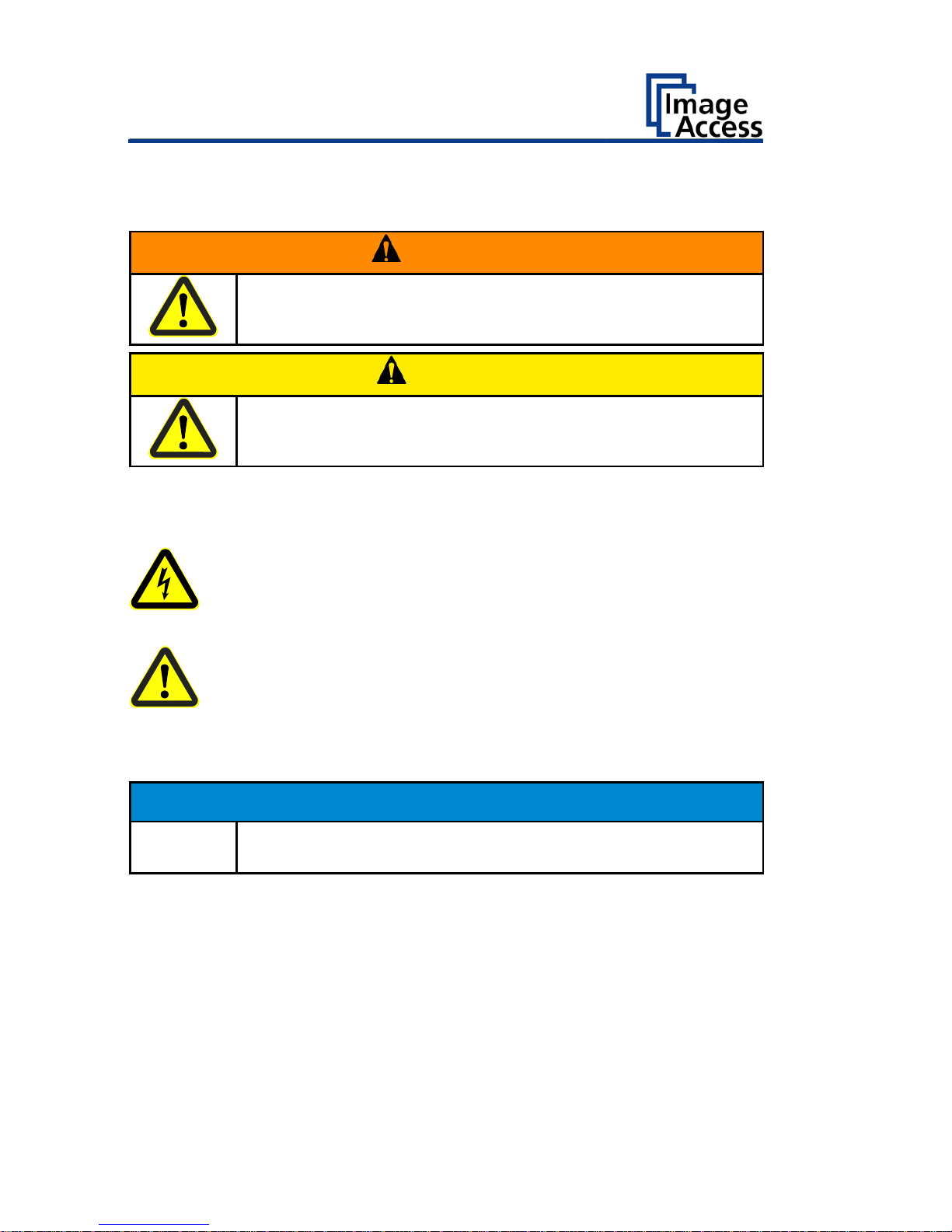
Design Features of Warning Notices
In these instructions, the following warning information can be found:
WARNING
Notices with the word WARNING warn about a dangerous
situation that could lead to death or serious injuries.
CAUTION
Notices with the word CAUTION warn about a situation that
could lead to light or medium-scale injuries.
The following symbols are used in the warnings:
Symbol
Explanation
Danger from electrical shock
General danger symbol
Formatting of Information Regarding Property Damage
ATTENTION!
These notices warn of situations that can lead to property
damage.
Page 11

Description
11
Description
Purpose and Function
The scanner is used for scanning images and documents. It is designed for
use in enclosed spaces in the commercial sector. Intended use also
includes observing and following all instructions in these instructions,
especially the safety instructions. Any other use is considered to be
improper and will void the warranty and liability claims.
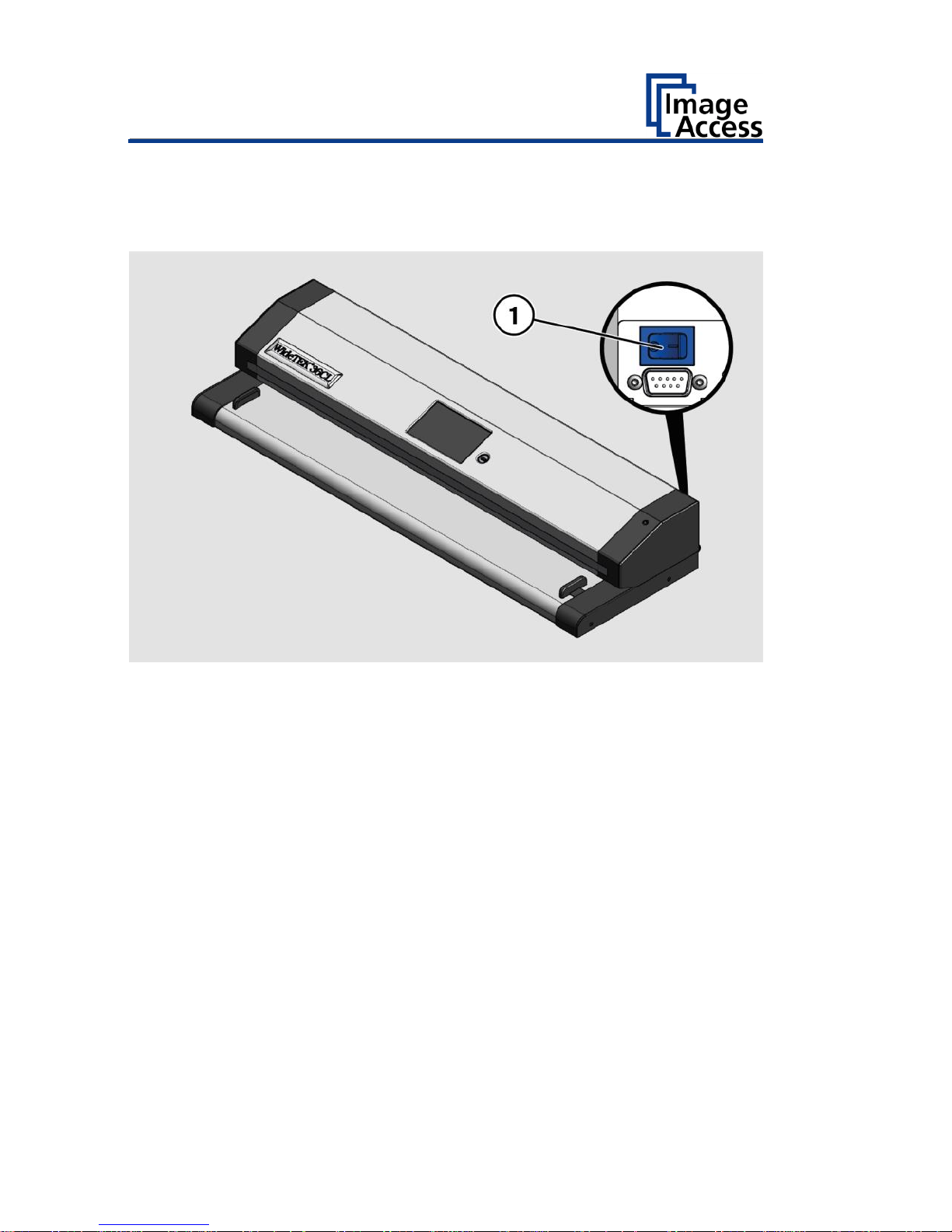
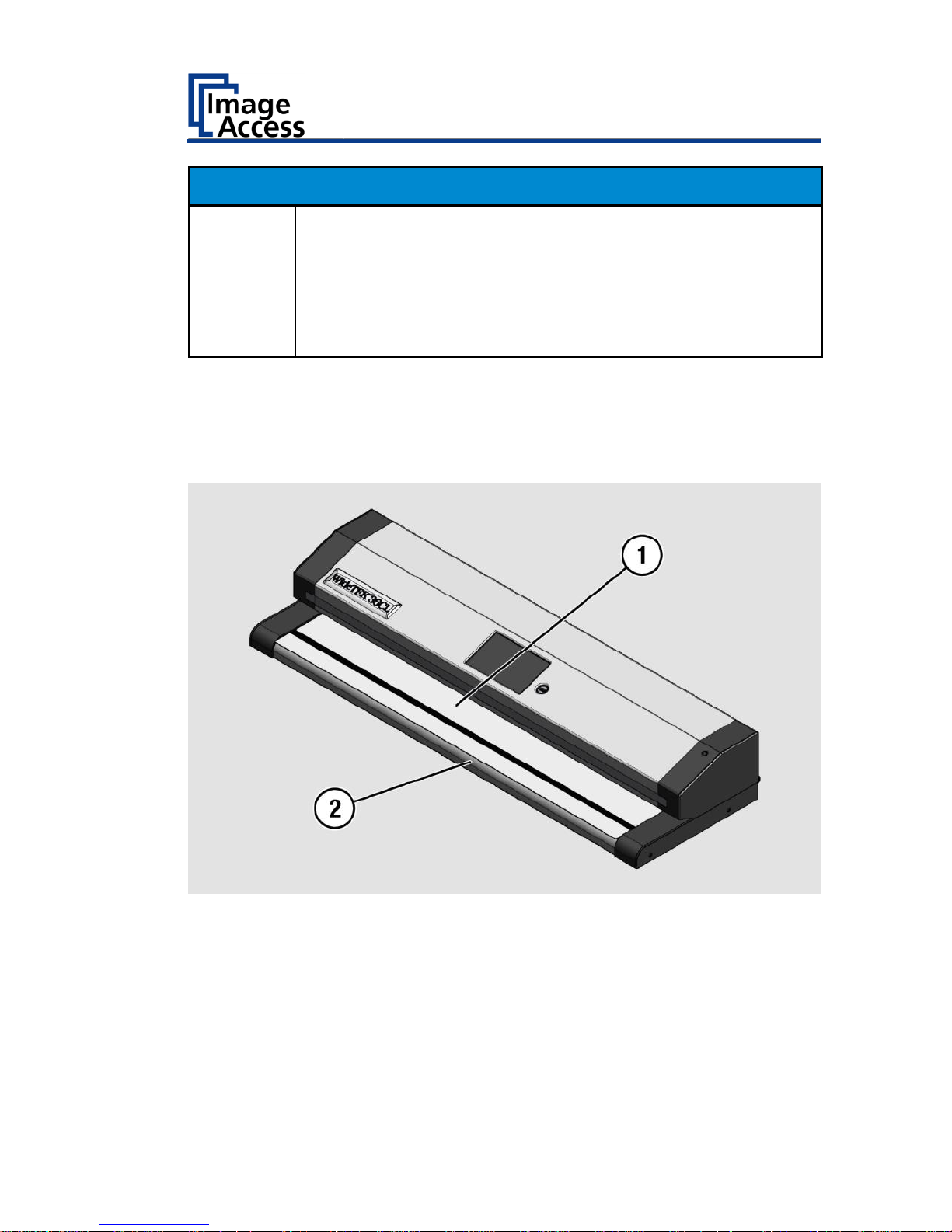
WideTEK® 36CL Overview
No.
Name
1
Document transport
2
Touchscreen
3
USB connector
4
Power button
5
Transport guides
Page 12

Description
12
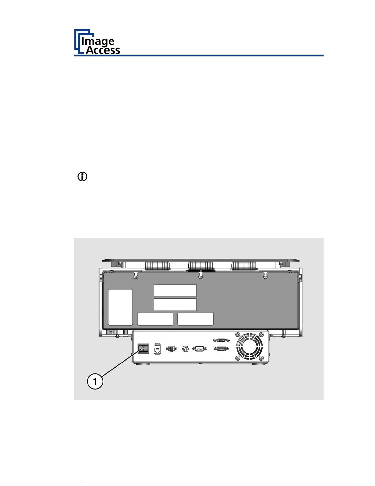
Rear View
No.
Name
1
USB connector
2
HDMI connector
3
Network connector
4
Recovery key connector
5
Main switch
6
19 V DC connector for external power supply
Page 13
Description
13
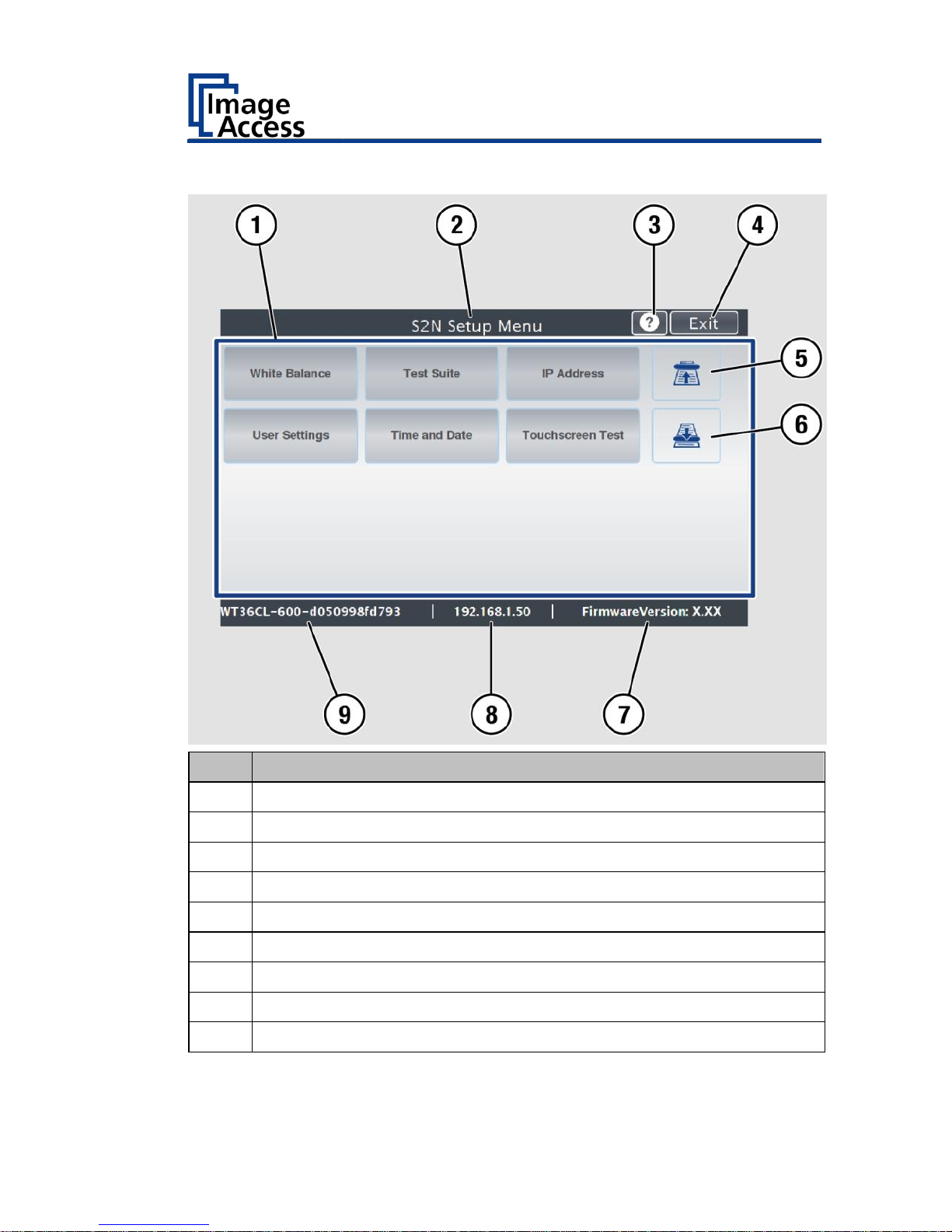
Setup Menu Overview Screen
No.
Name
1
Buttons and parameters
2
Menu name
3
Display the online help1
4
Button to leave the setup menu to the start screen
5
Button to drive the document forward in the scanner
6
Button to drive the document backward in the scanner (rewind).
7
Firmware version
8
IP address
9
Serial number
1
The display of the online help is only available when a second
touchscreen is connected to the scanner.
Page 14

Description
14
Rating Plate
The rating plate is attached to the back of the scanner.
Page 15
Prepare for Setup
15
Prepare for Setup
Connect the Power Supply
WARNING
Risk of electric shock due to incorrect connection.
Ensure that the power receptacle intended for the
connection is properly grounded.
Ensure that the power receptacle intended for the
connection of the scanner is properly fused.
CAUTION
Incorrect laying of the connection cables can cause tripping.
Fractures, contusions and bruises can be the result.
Place the connecting cables so that nobody can trip over
them.
To connect the power supply, proceed as follows:
Make sure that the main switch of the scanner is switched off (0
position).
Use only the AC adapter and power cord supplied.
Ensure the power cord is not damaged.
Connect the connector from the power supply to the associated 19 V DC
connector on the back of the scanner.
If not already done, connect the supplied power cable to the associated
connector on the power supply.
Connect the power plug of the power supply to a power receptacle of
the correct voltage (100-240 VAC).
Establish the Network Connection
CAUTION
Incorrect laying of the connection cables can cause tripping.
Fractures, contusions and bruises can be the result.
Place the connecting cables so that nobody can trip over
them.
Page 16
Prepare for Setup
16
To establish the network connection, proceed as follows:
Connect one plug of the enclosed network cable to the network
connector socket on the back of the scanner.
Connect the second plug to the network socket of an existing network.
Positioning the Scanner on the Optional Floor Stand
CAUTION
The scanner weighs 28 kg.
Only carry the scanner with a second person.
Ensure that the scanner is secured so that it does not fall
over.
To position the scanner on the optional floor stand, proceed as follows:
Assemble the floor stand according to the floor stand assembly
instructions.
Position the scanner on the floor stand as described in the
accompanying floor stand assembly instructions.
Connect the Optional Monitor
CAUTION
Incorrect laying of the connection cables can cause tripping.
Fractures, contusions and bruises can be the result.
Place the connecting cables so that nobody can trip over
them.
To connect the optional monitor, proceed as follows:
Connect the HDMI connector plug of the monitor to the HDMI
connector socket, located on the back of the scanner.
Page 17
Prepare for Setup
17
Connect the Optional Touchscreen
CAUTION
Incorrect laying of the connection cables can cause tripping.
Fractures, contusions and bruises can be the result.
Place the connecting cables so that nobody can trip over
them.
To connect the optional touchscreen, proceed as follows:
Connect the HDMI connector plug of the touchscreen to the HDMI
connector socket, located on the back of the scanner.
Connect the USB connector plug of the touchscreen to the USB
connector socket, located on the back of the scanner.
Page 18
Prepare for Setup
18
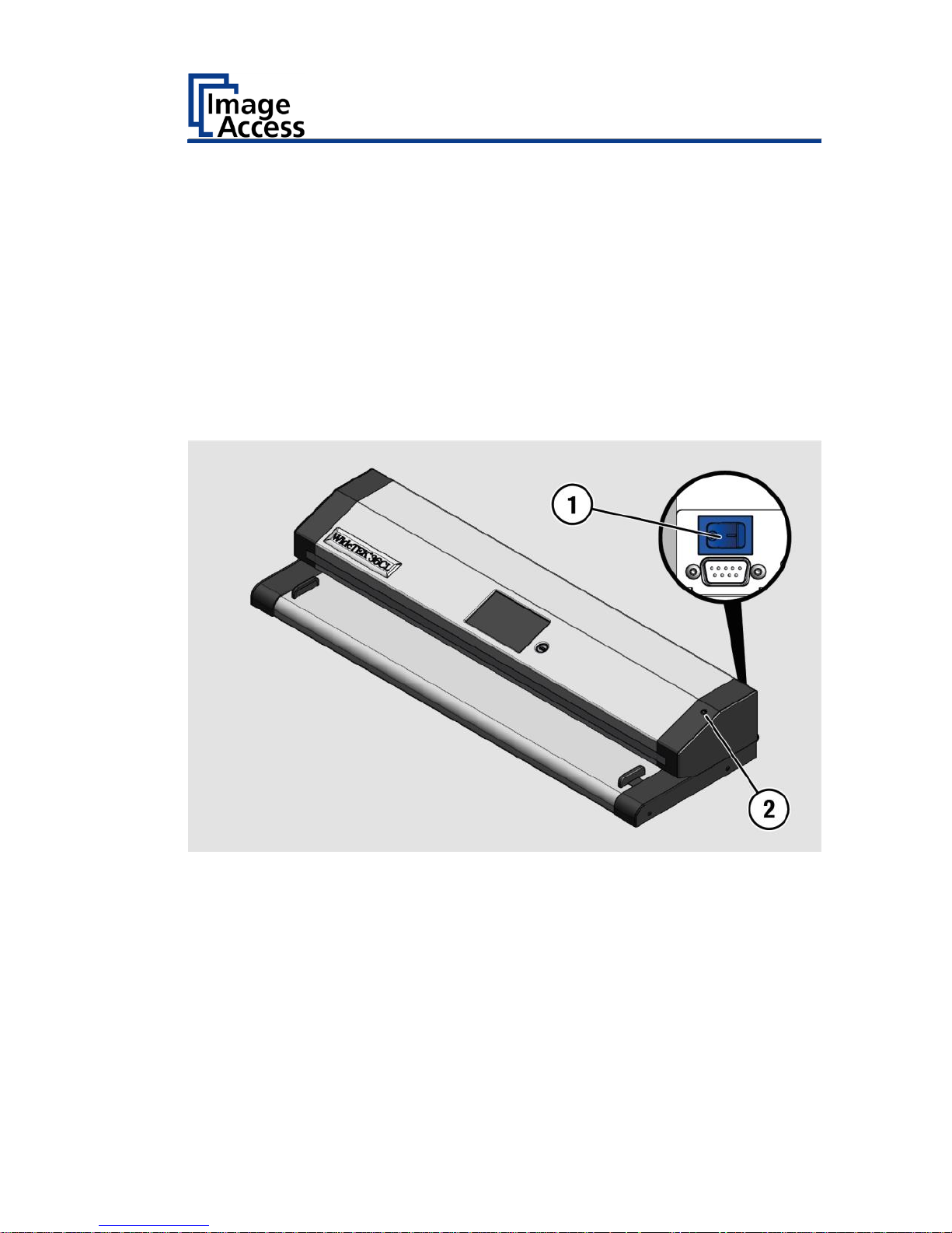
Switch On the Scanner
To switch on the scanner, proceed as follows:
Press the MAIN SWITCH (1) on the back to the "I" position.
The scanner is in standby mode. The power button is illuminated in green.
Page 19

Prepare for Setup
19
To start the scanner from standby mode, proceed as follows:
Touch the green illuminated power button.
The power button lights up in blue.
The scanner performs a system test. After a short wait, the "Start screen"
is displayed in English.
Page 20
Prepare for Setup
20
Switch Off the Scanner
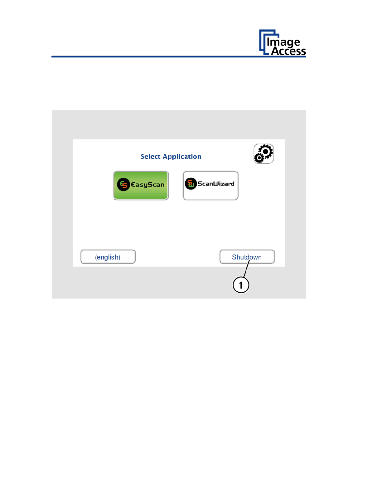
To switch the scanner to standby mode after performing the setup,
proceed as follows:
On the "Start screen" screen tap on SHUTDOWN (1).
Confirm with YES.
The scanner shuts down. This process can take up to 40 seconds.
The power button lights up green. The scanner is in standby mode.
Page 21
Prepare for Setup
21
Alternatively, switch the scanner into the standby mode as follows:
Touch the blue illuminated power button (2) and confirm the action in
the dialog on the touchscreen.
The scanner shuts down. This process can take up to 40 seconds.
The power button lights up green. The scanner is in standby mode.
To switch off the scanner for longer periods, proceed as follows:
Make sure that the scanner is in standby mode.
The power button is illuminated in green.
Press the MAIN SWITCH (1) in the "0" position.
To switch off the scanner using a hard shutdown, proceed as follows:
Press and hold the power button for longer than four seconds.
The power supply to the scanner is immediately interrupted.
The power button is illuminated in green.
Press the MAIN SWITCH (1) in the "0" position.
Page 22

Perform Setup
22
Perform Setup
Change the Menu Language
To change the menu language, proceed as follows:
Tap the LANGUAGE (1) button.
Page 23
Perform Setup
23
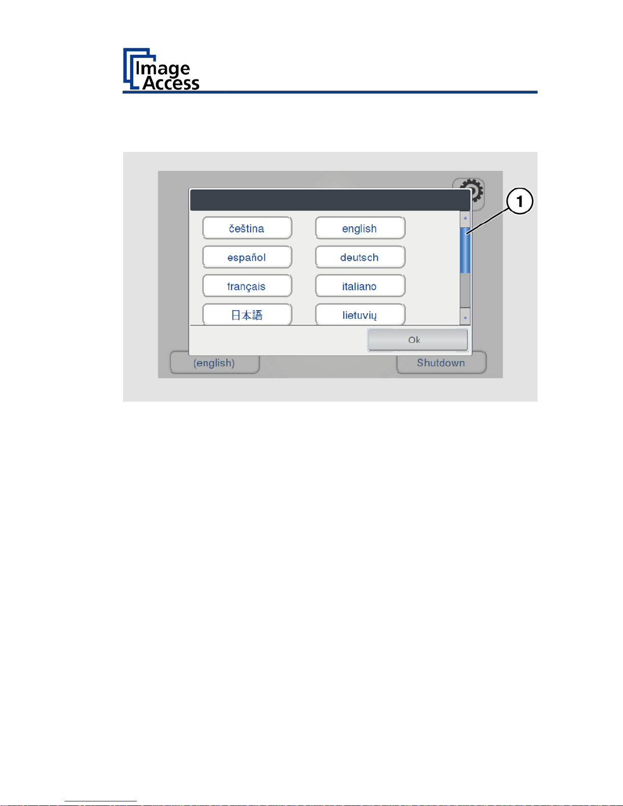
A window for selecting the language appears.
To display more languages, slide the scroll bar (1) downward.
Tap the desired language.
The window for selecting the language is closed. The "Start screen" is
displayed.
Page 24

Perform Setup
24
Activate the Setup Menu
To activate the setup menu, you have to log in on the scanner. Proceed as
follows:
Tap the GEAR SYMBOL (1).
Page 25
Perform Setup
25
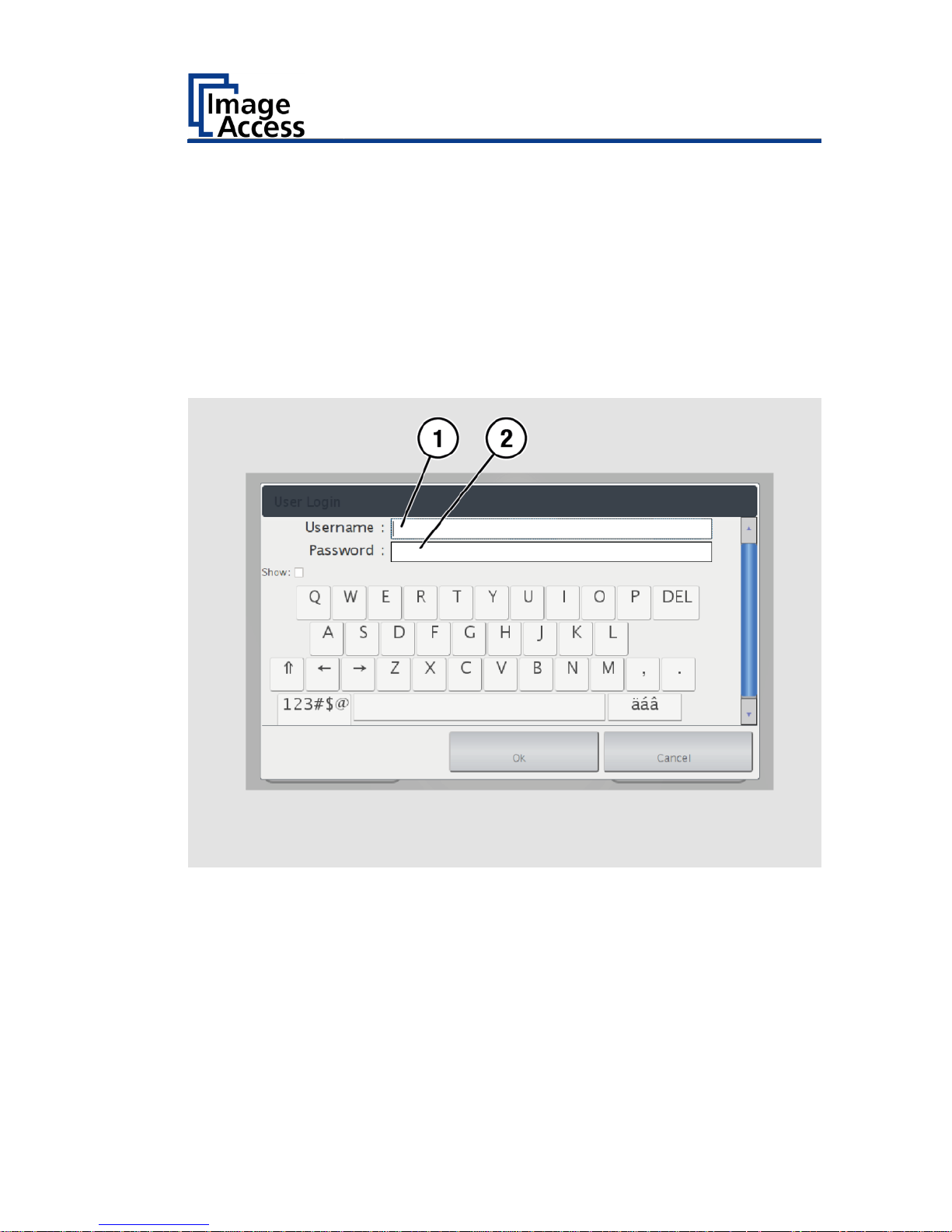
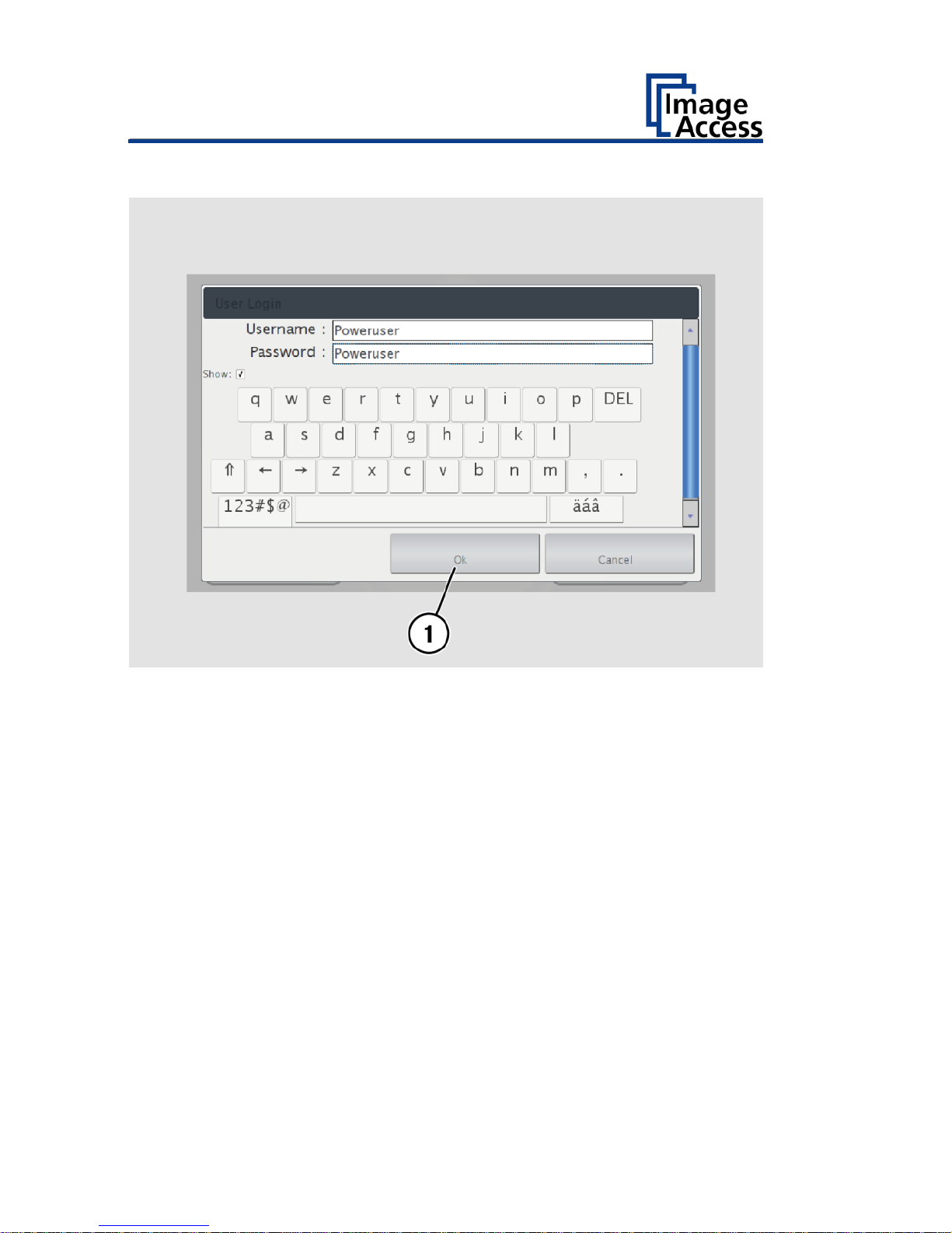
The login window appears.
In the login window, enter the login credentials.
To enter the credentials, tap with your finger on the corresponding
input field.
The screen keyboard is displayed.
Enter the word "Poweruser" in the fields "Username" (1) and
"Password" (2).
Please note that the input is case sensitive.
Page 26
Perform Setup
26
To complete the log in, press OK (1).
Page 27
Perform Setup
27
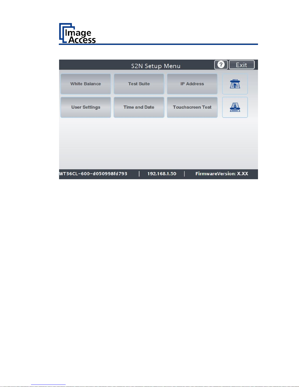
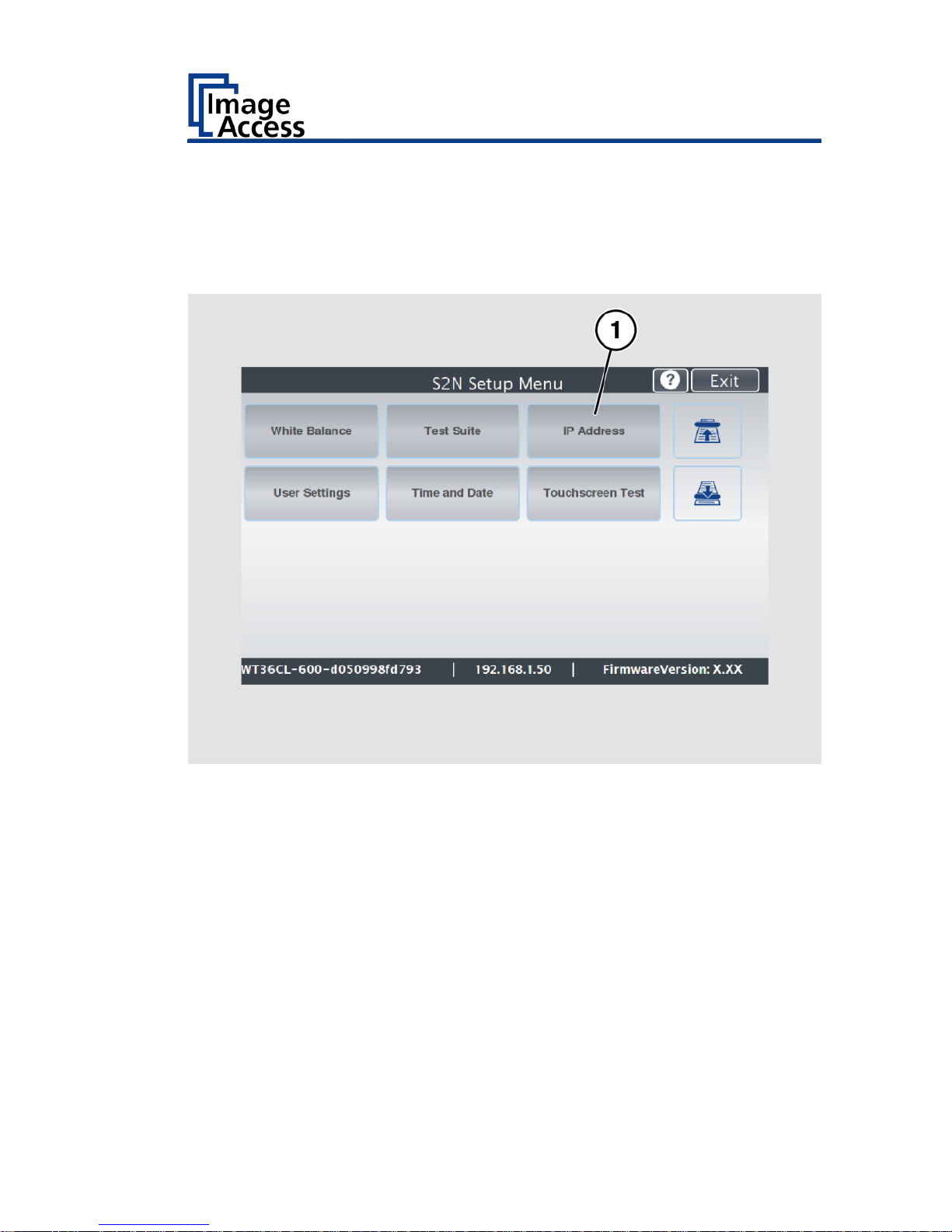
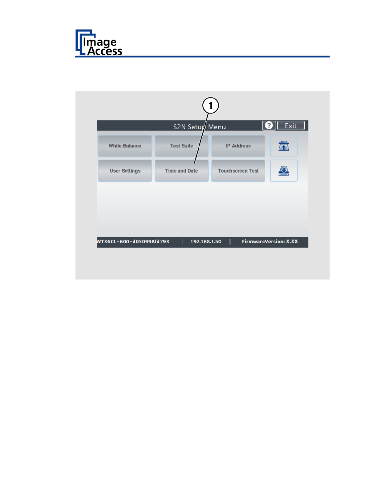
The "Setup Menu" screen is displayed.
White Balance:
Display the "White balance" submenu
Test Suite:
Display the "Test Suite" submenu
IP Address:
Display the "IP Address" submenu
User Settings:
Display the "User Settings" submenu
Time and Date:
Display the "Time and Date" submenu
Touchscreen Test:
Display the "Touchscreen Test" submenu
To select a submenu from the "Setup menu" screen, tap with your
finger on the button of the screen.
Page 28

Perform Setup
28
Perform White Balance
On the "Setup Menu" screen, tap on WHITE BALANCE (1).
Page 29
Perform Setup
29
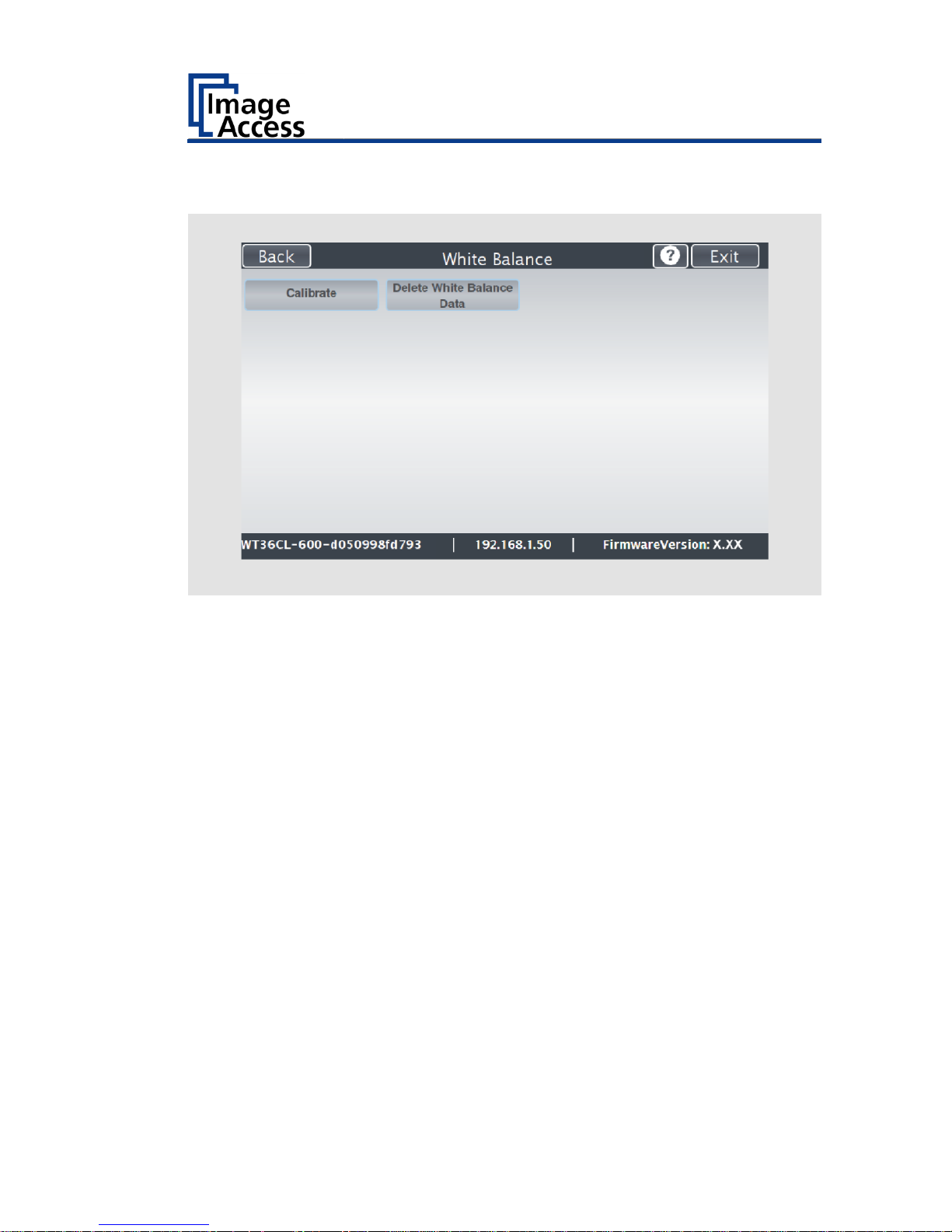
The "White Balance" screen is displayed.
Calibrate:
Start white balance
Delete White
Balance Data:
Delete existing white balance data
The white balance is used to ensure the quality of the scan results. The
white balance will be carried out using a test target. The test target is
marked as follows:
WT36C-Z-01-A.
Page 30
Perform Setup
30
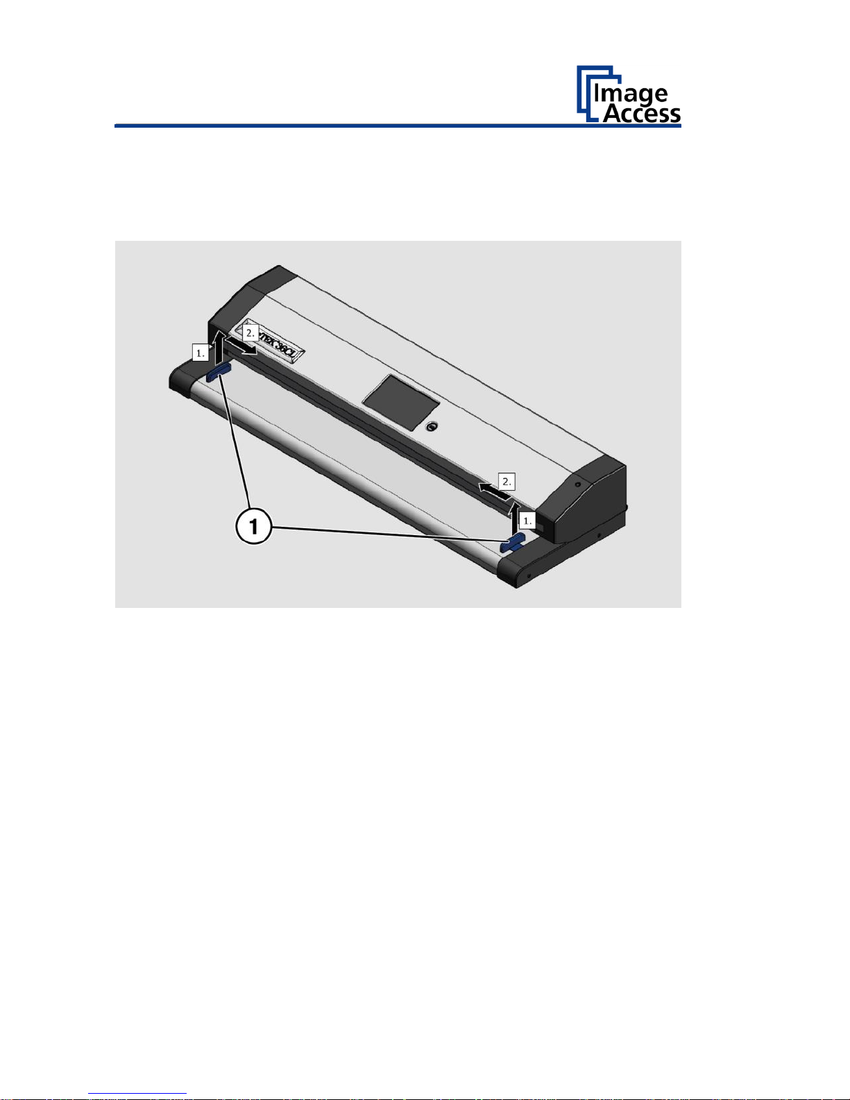
Before beginning the white balance procedure, remove the transport
guides. To remove the transport guides, proceed as follows:
Lift the transport guides (1) approximately 5 mm (1.).
Pull the transport guides (1) inwards (2.).
Page 31
Perform Setup
31
ATTENTION!
Impairment of the scan quality can occur if an improper
test target for the white balance is used.
Make sure that the test target is free from wrinkles,
discolorations, cracks or other damage.
Store the test target for the white balance in a safe place
protected from daylight.
To perform the white balance, proceed as follows:
Position the supplied test target (1) in the document transport as
illustrated below (2).
The test target (1) is pulled into the scanner.
Page 32

Perform Setup
32
Tap on CALIBRATE (1).
Page 33

Perform Setup
33
Tap on NEXT STEP (1).
Page 34

Perform Setup
34
The white balance starts and the calibration is performed. During the white
balance, a rotating icon appears. The test target is transported forward and
returned. The entire white balance sequence takes about 18 seconds.
Then, the white balance result is displayed as shown on the example
below.
On an error-free white balance calibration, the result is displayed in
green.
An incorrect result is displayed in red. If this is the case, the white
balance starts over again.
Page 35

Perform Setup
35
To perform the white balance again, tap NEW VALUES (2).
To return to the previous submenu, tap BACK (1).
To return to the "Start screen", tap EXIT (3).
Page 36

Perform Setup
36
To delete the stored data of the white balance calibration, tap DELETE
WHITE BALANCE DATA (2).
After deleting the stored data, run the white balance again, as
described.
If problems arise during the white balance calibration, contact Image
Access technical support, see section Technical Support starting at page
6.
To return to the previous submenu, tap BACK (1).
To return to the "Start screen", tap EXIT (3).
After a successful white balance, proceed as follows:
Remove the test target.
Put the transport guides back into their position.
Store the test target in a place which is protected from daylight.
Ensure that the test target is not damaged, bent or soiled.
Page 37
Perform Setup
37
Assign the IP Address
Manually Assign the IP Address
To manually assign the IP address, proceed as follows:
On the "Setup Menu" screen, tap on IP Address (1).
Page 38
Perform Setup
38
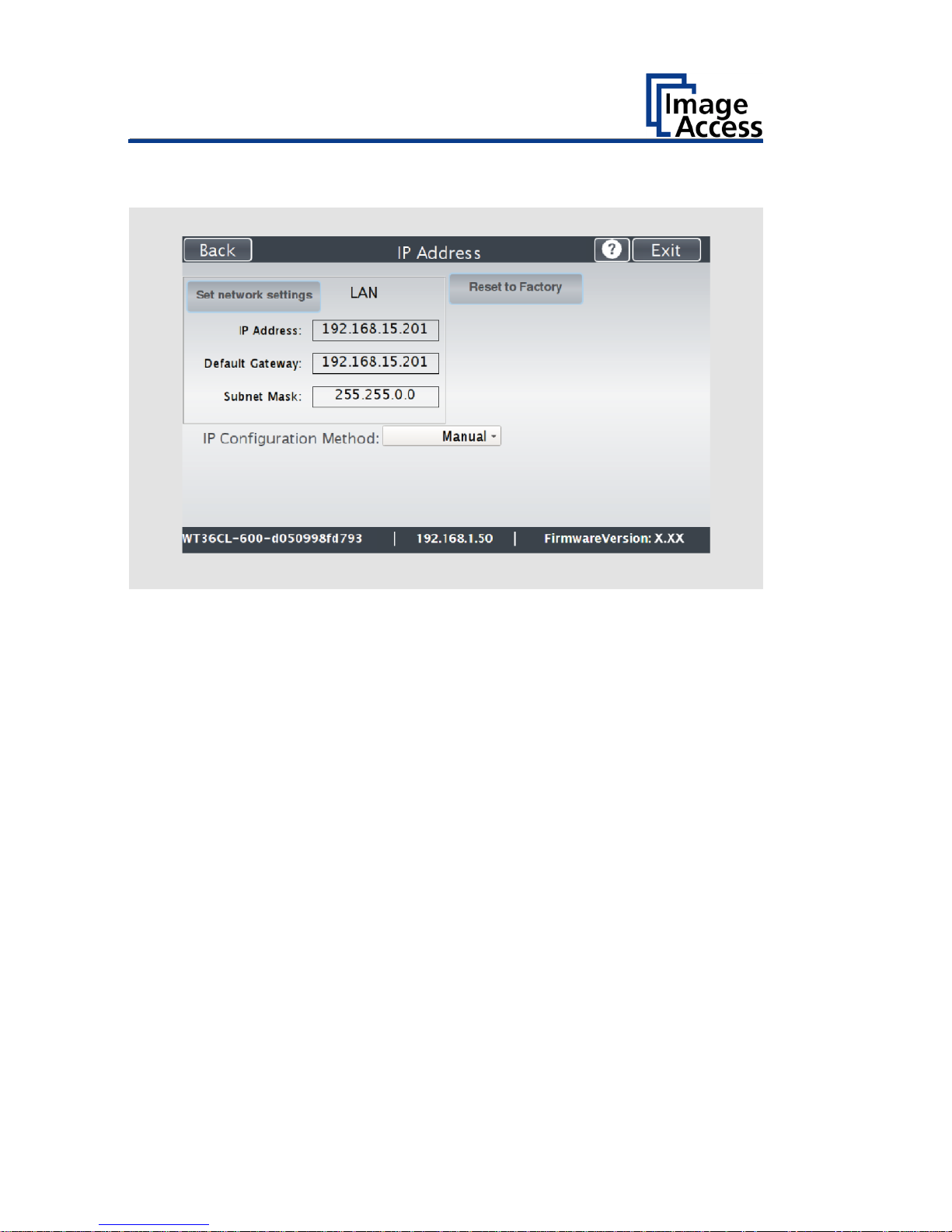
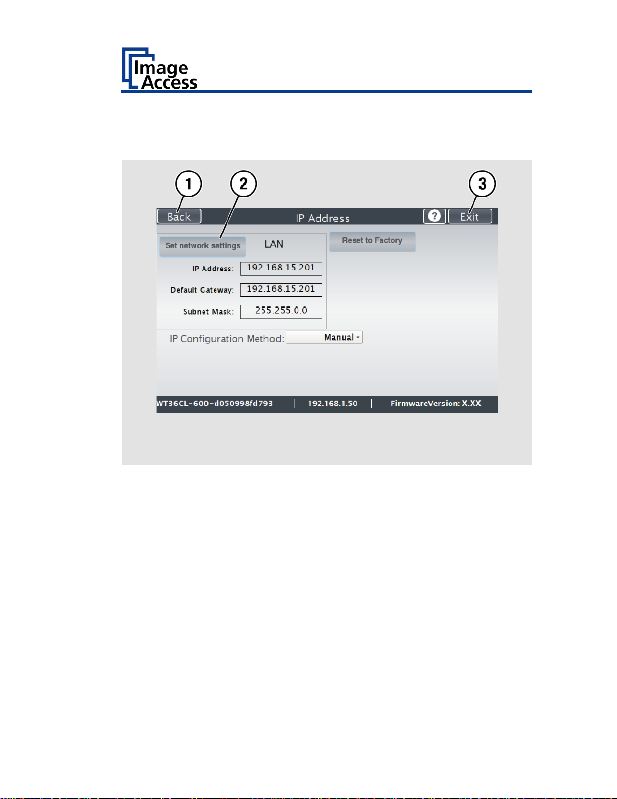
The "IP Address" screen is displayed.
Set network
settings:
Accept the network settings provided
Reset to Factory:
Reset to factory settings
IP Address:
Input field for the IP address
Default Gateway:
Input field for the gateway address
Subnet Mask:
Input field for data on the subnet mask
IP Configuration
Method
Manual/DHCP:
Assign an IP address manually or automatically
Page 39

Perform Setup
39
Tap the "IP Address" (1) field.
Page 40

Perform Setup
40
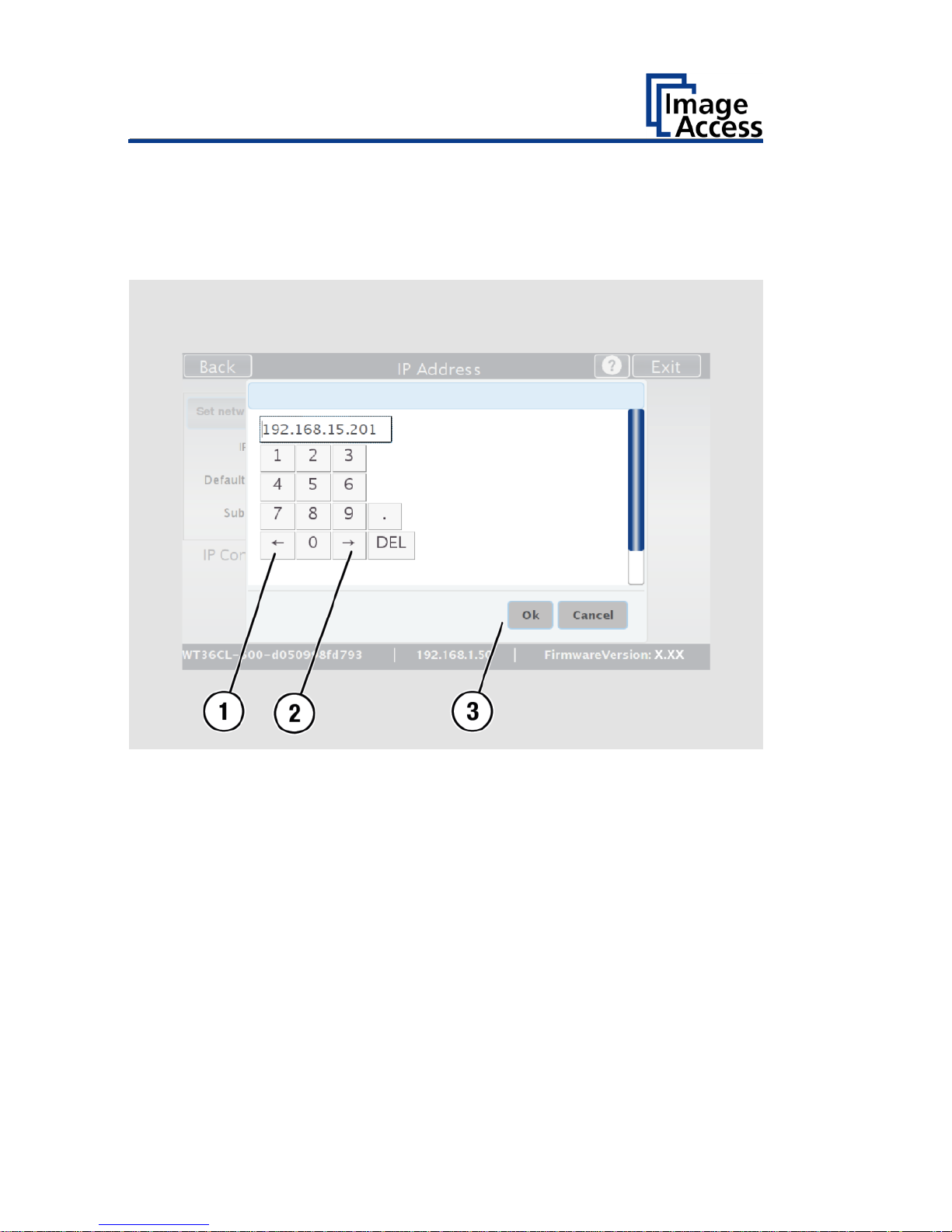
The "IP Address" window is displayed.
Enter the IP address (1).
Page 41

Perform Setup
41
To delete a digit, move the cursor to the right, behind the digit to be
deleted and tap DEL (1).
Page 42
Perform Setup
42
The arrow keys left (1) and right (2) next to the number "0" move the
cursor within the chosen row.
To complete the entry, press OK (3).
Perform the settings for gateway and subnet mask in the same way.
Page 43
Perform Setup
43
To save the network settings, tap SET NETWORK SETTINGS (2).
To return to the previous submenu, tap BACK (1).
To return to the "Start screen", tap EXIT (3).
Page 44

Perform Setup
44
Automatically Assign the IP Address
To automatically assign the IP address, proceed as follows:
On the setup menu screen, press the button IP ADDRESS (1).
Page 45

Perform Setup
45
In the selection menu "IP Configuration Method", select the "DHCP" (3)
entry.
To return to the previous submenu, tap BACK (1).
To return to the "Start screen", tap EXIT (2).
Page 46

Perform Setup
46
Modify User Settings
On the "Setup Menu" screen, tap on USER SETTINGS (1).
Page 47

Perform Setup
47
The "User Settings" screen is displayed.
Configure GUI
Selection:
Open the submenu for setting the application in
the start screen
Default:
The scanner default settings will be established
again
Language:
Select language
Display standby
after:
Define the period of inactivity, until an optional
external monitor and the touchscreen switch to
the standby mode
Screen Saver after:
The period of inactivity is defined until the screen
saver is activated
Device standby
after:
The period of inactivity is defined, until the
scanner goes into standby mode
Page 48

Perform Setup
48
Select Language
To select the language, proceed as follows:
Tap the on the selection arrow of the selection menu "Language" to
display the list of languages.
Tap the desired language (2).
To return to the previous submenu, tap BACK (1).
To return to the "Start screen", tap EXIT (3).
Page 49

Perform Setup
49
Set Standby Times
To set the standby times, proceed as follows:
Tap the selection arrow of the selection menu.
Tap on the desired entry (2).
Perform the settings for the screen saver and the device standby in the
same way.
To return to the previous submenu, tap BACK (1).
To return to the "Start screen", tap EXIT (3).
Page 50

Perform Setup
50
Configuring the GUI Selection
Tap the "User Settings" screen on CONFIGURE GUI SELECTION (1).
Page 51

Perform Setup
51
The "Configure GUI Selection" screen is displayed.
This menu displays the "EasyScan" and "ScanWizard" applications, which
are available as a standard selection. If after system start you want to
display only one of the applications, proceed as follows:
Under "Displays" (1) disable the box corresponding to the application
you do not want to display.
Page 52

Perform Setup
52
By default, job mode is defined (disable the checkbox "Single mode
enabled").
To start the application in standalone mode, check the checkbox "Single
mode enabled" (2).
To return to the previous submenu, tap BACK (1).
To return to the "Start screen", tap EXIT (3).
Page 53
Perform Setup
53
Set the Time and Date
On the "Setup Menu" screen, tap on TIME and DATE (1).
Page 54

Perform Setup
54
The screen "Time and Date" appears.
Enter new time:
Enter hours and minutes with the arrow keys
Enter new date:
Open a calendar to set the date
Store time and
date:
Accept the set values
Time Zone:
Select a time zone
Page 55

Perform Setup
55
To set the time, proceed as follows:
Tap the "Enter new time" field.
To set the time later, tap the up arrow (2).
To set the time earlier, tap the down arrow (2).
To save the modified time, click STORE TIME AND DATE (3).
To return to the previous submenu, tap BACK (1).
To return to the "Start screen", tap EXIT (4).
Page 56

Perform Setup
56
To set the date, proceed as follows:
Tap the "Enter new date" field.
A calendar (3) is displayed.
Select the appropriate date in the calendar (3).
To set the month and year, tap the arrow keys (2, 4) at the top of the
calendar.
To set the day, tap the corresponding day in the calendar.
To save the date, click STORE TIME AND DATE (5).
To return to the previous submenu, tap BACK (1).
To return to the "Start screen", tap EXIT (6).
Page 57

Perform Setup
57
To select the time zone, tap the selection arrow (4).
A selection list with available time zones is displayed.
Select the appropriate time zone.
To save the time zone, click STORE TIME AND DATE (2).
To return to the previous submenu, tap BACK (1).
To return to the "Start screen", tap EXIT (3).
Page 58
Perform Setup
58
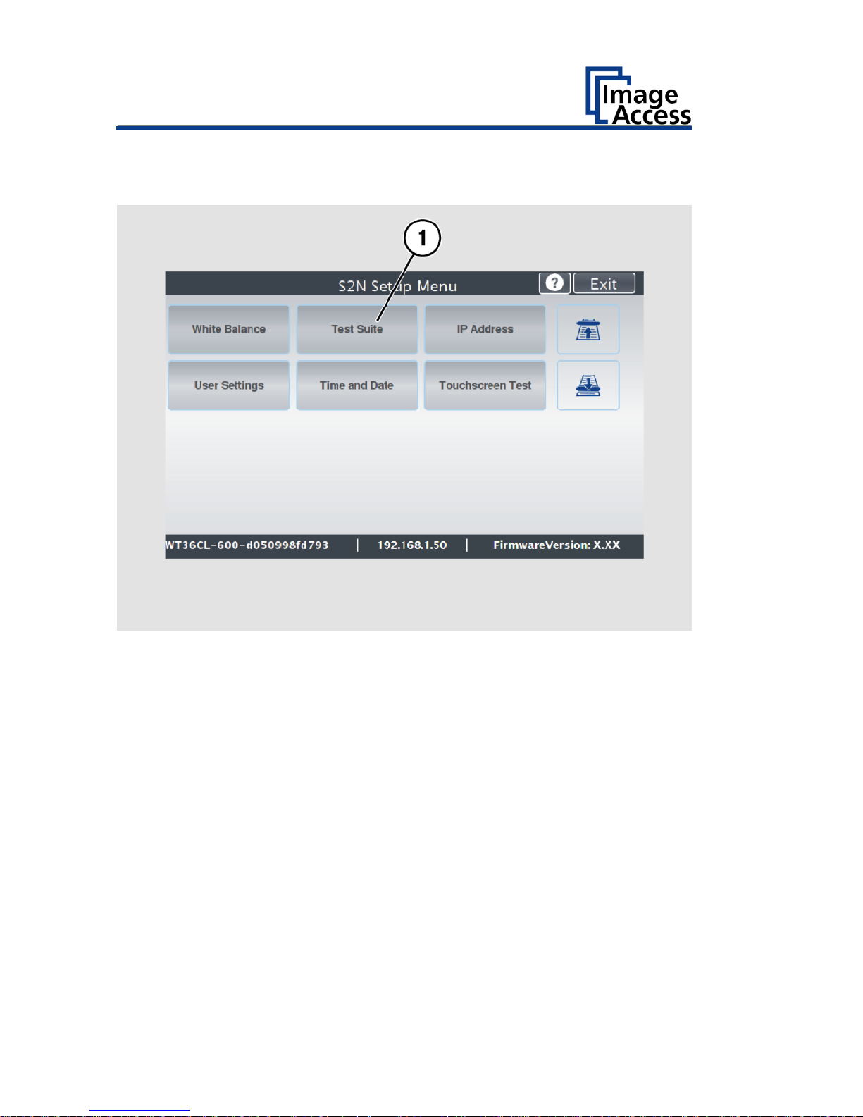
Perform Test Suite
On the "Setup Menu" screen, tap on TEST SUITE (1).
Page 59

Perform Setup
59
The "Test Suite" screen is displayed.
Information about
the mainboard:
Display the current values for:
Temperature of PCB and CPU cores, fan speed,
PCB voltages
Information for
testing
electromagnetic
compatibility:
Off/On
Page 60

Perform Setup
60
Testing electromagnetic compatibility (EMV test)
The EMV test may only be performed by certified service technicians.
To perform the electromagnetic compatibility test, select "on" (3) in the
"EMV Test" selection menu.
To return to the previous submenu, tap BACK (1).
To return to the "Start screen", tap EXIT (2).
Page 61
Perform Setup
61
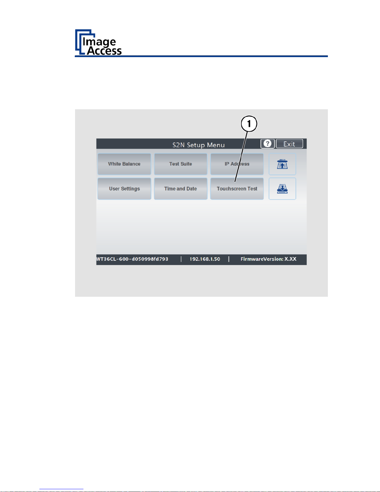
Touchscreen Test
To check the functionality of the touchscreen when touched, proceed as
follows:
On the "Setup Menu" screen tap on TOUCHSCREEN TEST (1).
Page 62
Perform Setup
62
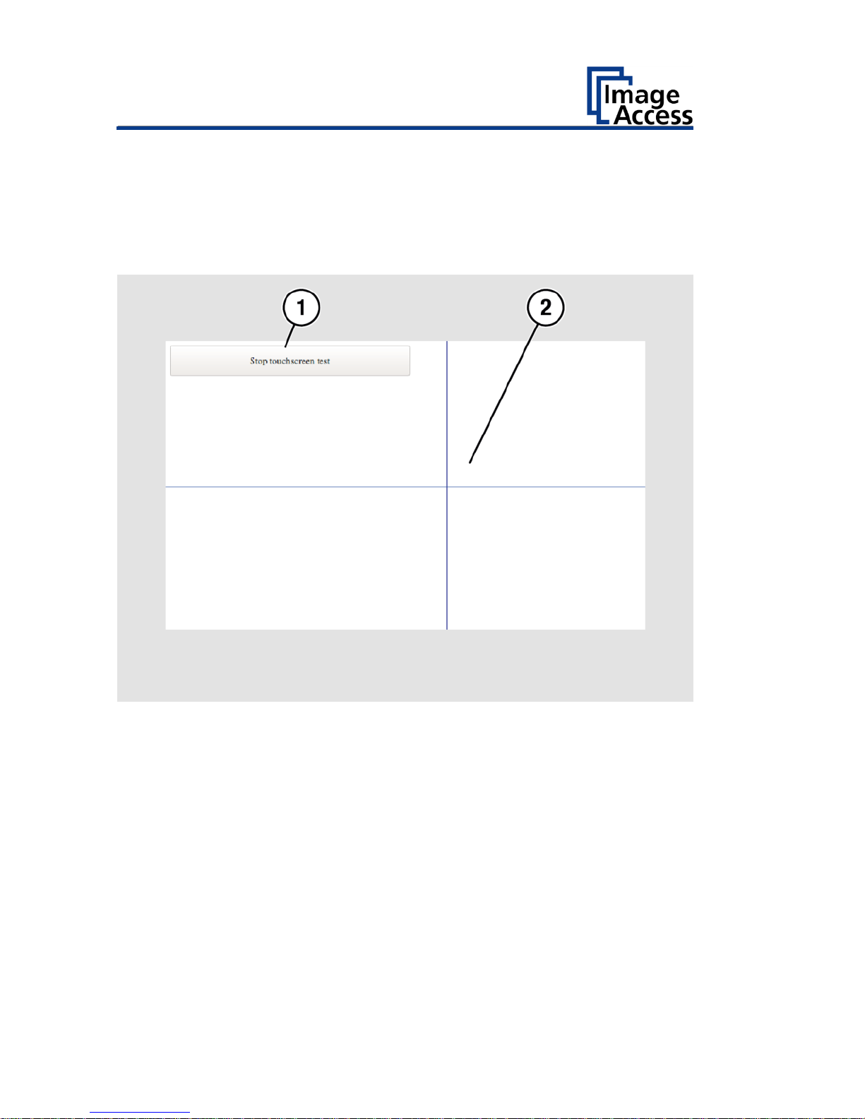
The "Touchscreen test" screen is displayed.
Tap with your finger on the corresponding screen (2).
The cross-lines must occupy the same position as the finger.
To end the "Touchscreen test", tap STOP TOUCHSCREEN TEST (1).
The "Start screen" is displayed.
Page 63

Technical Specifications
63
Technical Specifications
WideTEK® 36CL Scanner Specification
Optical System
Maximum document size
965 mm / 38 inch
Scan width
915 mm / 36 inch
Scanner resolution
1200 × 1200 dpi
(optional 9600 × 9600 dpi
interpolated)
Color Depth
48 bit color (internal resolution)
Scan modes
24 bit color, 8 bit color indexed, 8
bit grayscale
bitonal, halftone
File formats
Multipage PDF (PDF/A) and TIFF,
JPEG, JPEG 2000, PNM, PNG, BMP,
TIFF (Raw, G3, G4, LZW, JPEG),
AutoCAD DWF, JBIG, DjVu, DICOM,
PCX, Postscript, EPS, Raw data
Ambient Conditions
Ambient temperature during
operation
+5 to +40 °C
Storage temperature
0 to + 60 °C
Relative humidity
20 to 80 % (non-condensing)
Noise development
≤ 35 dB(A) (Scanning)
≤ 25 dB(A) (Standby)
Page 64

Technical Specifications
64
Electrical Data
External Power Supply
Input Voltage
100–240 Vac
Frequency
47–63 Hz
Output voltage
19 Vdc
Output current
3,15 A
ECO Standard
CEC Level VI
Scanner
Input voltage
19 Vdc
Input current (fused)
max. 3 A
Power Consumption
Sleep mode
≤ 0,5 W
Standby mode
approx. 5,2 W
Ready to scan
< 25 W
Scanning
< 45 W
Page 65

Technical Specifications
65
Document specifications
Document length
up to 500 m / 20.000 inch1
Paper weight
any
Document thickness
2,5 mm / 0,1 inch max.
1
The maximum document length depends on the scan resolution and the
scan mode.
Page 66

Technical Specifications
66
Dimensions and Weight
Scanner (H × W x D)
170 x 1088 x 358 mm
Scanner weight
24 kg
Floor stand weight
19 kg
Transport box scanner
(H × W x D)
250 x 1160 x 440 mm
Transport box floor stand
(H × W x D)
110 x 27 x 14,5 mm
Scanner weight, ready to ship
32 kg
Floor stand weight, ready to ship
21 kg
End of document
Page 67

Page 68

 Loading...