

Page 1

Operation Manual
Page 2

Art
File: WT36C_WT48C_OperationManual_E.docx
-Nr.: WT36C/48C-600-MAN-EN
Page 3

2010 – 2015 by Image Access GmbH, Wuppertal, Germany.
Printed in Germany. All rights reserved.
Reproduction in whole or in part in any form or medium without express written permission of
Ima
Scan2Net
All other trademarks are the property of their respective owners.
Image Access reserves the right to change the described products, the specifications or
documents at any time without prior notice.
For the most recent version, always check o
or
www.imageaccess.us or the customer service portal at portal.imageaccess.de
ge Access is prohibited.
®
, WideTEK® and Bookeye® are registered trademarks of Image Access.
ur web site www.imageaccess.de
Manual Page 3
Page 4

Introduction
Dear Customer,
The Image Access team congratulates you on the acquisition of this innovative large
format scanner.
We at Image Access are proud of the work we do; it is the result of our extremely high
standards of production and stringent quality control.
®
With the WideTEK
which covers a wide scope of applications due to its versatility. Its integrated web
based user interface makes all functions available in structured menus.
36C / WideTEK® 48C, Image Access offers an efficient scanner
This operation manual is designed to lead you through all situations which will arise
when using the WideTEK
®
36C / WideTEK® 48C.
For this reason, we ask you to read the manual at tentively before starting to work with
the sanner. By doing so, you will avoid operation errors and you can control all
functions from the beginning.
In addition please consider the following points:
• Damages to your unit may have occurred during shipping. Please check for
damages immediately after delivery of the unit. Inform your supplier if damage
has occurred.
• Read and ensure that you understand the safety notes. They were developed
for your protection and safety as well as to protect the unit.
• Regular maintenance conserves the high quality and safety of the
®
WideTEK
36C / WideTEK® 48C during the entire service life.
If you have any further questions, please feel free to contact your local dealer or
Image Access, Inc. directly. Our staff will be happy to help you.
®
For your daily work with the WideTEK
36C / WideTEK® 48C scanner, we wish you
success and complete satisfaction.
Regards
Your Image Access Team
Page 4 Manual
Page 5

About this Manual
Operation Manual
The Operation Manual gives all information about the normal operation and behavior
of the device. It is written for people who only operate the device and do not perform
setup and adjustment procedures. All device elements and software functions are
described in detail, although some of them might never be used. This manual does not
cover any application software. Refer to the appropriate application software manual to
learn about the application software.
All available manuals for this device can be downloaded from our customer service
portal at http://portal.imageaccess.de
these manuals.
This manual is divided into sections.
Section A contains the safety notes and the safety precautions. These safety
precautions must be followed carefully to avoid injury to the user while
working with the scanner.
. Be sure to always check for the latest versions of
Section B describes the scanner hardware and the first steps to take after the
device has been delivered. It contains also some maintenance
information.
Section C describes touchscreen operation and the functions of the applications.
Section D gives a short introduction and basic information about t he user interface
ScanWizard Web. All details about the interface can be found in the
integrated “Help” texts in the scanner.
Section E informs about the setup levels in general and describes the acces s level
User in detail.
Section F describes test and troubleshooting procedures.
Section G contains all technical data of the scanner and the manufacturer
declarations concerning safety and electromagnetic compatibility (EMC).
Manual Page 5
Page 6

Version
Published in
Content/Changes/Supplements
A2
July 2011
Information after EMC and safety testing and certification added.
renumbered to
Content of chapter C.5.2 revised, new screenshots added.
A4
October 2011
Chapter B.6.3.1 added. In Chapter C.3.3 additional information
Chapter C.3.7.2
FCC note added in chapter E.6.
A5
December 2011
Update Technical Data
B
April 2012
Update of content of User Settings (FW Vers. 5.71).
New structure in chapter C.3.5 and its subfolder.
New screen screenshots of some kiosk application screens.
B2
June 2013
Section D describes now the “ Setup Le vel”. Form er chapter D and
E have been renumbered.
Section C: Content change because of introduction of the new
user interface ScanWizard.
D
April 2014
Combination of the
/
operation
Chapter B.1.1, chapter D.1.3.2, chapter D.1.3.4 added.
D2
September 2014
Chapter C.1.1 and C.1.1 added. Table in chapter E.1 modified.
E
December 2015
Chapters in new order. Description of the ScanWizard touchscreen
interface added.
EMC information according to the standard EN 55022
device. Operation of these equipment in a residential area is likely to
cause harmful interference in which case the user will be required to correct the
Version History
A May 2011 Preliminary version.
A3 September 2011 Chapter C.3.9: New content, former chapter C.3.9
C.3.10.
about “Container” format for multipage output.
added.
B1 March 2013 Valid with firmware 5.8.
Copyright note with updated trademark information.
The new WideTEK
New: Chapter B.5.1. Zonal OCR
Previous chapter B.5.1 and all following chapters renumbered.
®
36C logo has been intro duc ed .
C December 2013
Warning!
WideTEK® 36C
manuals in one manual.
Differences between the scanner models will be highlighted.
Chapter B.3.2, B.3.3, B.3.5 and B.3.6 with ne w conte nt .
WideTEK® 48C
This is a class A
interference at his own expense.
Page 6 Manual
Page 7

Table of Content
Introduction -------------------------------------------------------------------------- 4
About this Manual ----------------------------------------------------------------- 5
Version History --------------------------------------------------------------------- 6
A Safety Notes ------------------------------------------------------------------- 16
A.1 General Notice ................................................................................................... 16
A.2 Safety Notes ...................................................................................................... 16
A.2.1 Marking of Safety Notes 16
A.3 Certification ........................................................................................................ 16
A.4 Safety Precautions ............................................................................................. 17
B Hardware ----------------------------------------------------------------------- 18
B.1 Content on Delivery ............................................................................................ 18
B.1.1 WideTEK® 36C 18
B.1.2 WideTEK® 48C 20
B.1.3 Keeping the Transport Box for later use 21
B.2 Device Overview ................................................................................................ 22
B.2.1 Front Side Elements 22
B.2.2 Rear Side Connectors 23
B.2.3 Recovery Key Connector 24
B.3 Connecting to the Power Source ........................................................................ 25
B.4 Powering up the Scanner ................................................................................... 26
B.4.1 Starting the Scanner from Standby Mode 26
B.4.2 Switching the Scanner to Standby Mode 26
B.5 Device Location.................................................................................................. 27
B.6 Maintenance ...................................................................................................... 28
B.6.1 Touchscreen 28
B.6.2 Surfaces 28
B.6.3 Camera Modules Glass Plates 28
B.7 Repair ................................................................................................................
Manual Page 7
28
Page 8

Table of Content, part 2
C Touchscreen Oper a t ion --------------------------------------------------- 29
C.1 Select Application Screen .................................................................................. 30
C.1.1 Document Transport Settings 31
C.1.1.1 Paper Feed Delay 31
C.1.1.2 Scan Mode 32
C.1.1.3 Document Output 32
C.1.1.4 Transport Speed 32
C.2 ScanWizard Application ..................................................................................... 33
C.2.1 Size 35
C.2.1.1 Format 35
C.2.1.2 Mirror 38
C.2.1.3 Splitting Image 38
C.2.1.4 Start Splitting 38
C.2.2 Quality 39
C.2.2.1 Color Mode 39
C.2.2.2 Color Space 40
C.2.2.3 ICC Profiles 40
C.2.2.4 Invert 40
C.2.2.5 DPI 41
C.2.2.6 Scan Mode 41
C.2.2.7 Stitching 41
C.2.3 Enhancement 42
C.2.3.1 Brightness 42
C.2.3.2 Contrast 42
C.2.3.3 Image Sharpness 42
C.2.3.4 Exposure 43
C.2.3.5 Threshold 44
C.2.3.6 Despeckle 44
C.2.4 Transport 45
C.2.4.1 Paper Feed Delay 45
C.2.4.2 Scan Mode 45
C.2.4.3 Transport Speed 46
C.2.4.4 Document Output 46
Page 8 Manual
Page 9

Table of Content, part 3
C.2.5 Transfer 47
C.2.5.1 Modifying an entry of the transfer target 48
C.2.5.2 USB 49
C.2.5.3 SMB 50
C.2.5.4 FTP 51
C.2.5.5 Default 52
C.2.5.6 Mail 53
C.2.5.7 Remote Printer 54
C.2.5.8 File Format 55
C.2.5.9 Compression 55
C.2.5.10 File Type 56
C.2.5.11 PDF Document 57
C.2.5.12 Embedded Metadata 58
C.2.5.13 OCR 58
C.2.6 Job Mode in ScanWizard application 59
C.2.6.1 Job mode, move image 61
C.2.6.2 Job Mode, rescanning an image 61
C.2.6.3 Job Mode, adding an image to the list at any position 61
C.2.6.4 Job Mode, deleting an image 62
C.2.6.5 Quit Job Mode 62
C.2.7 Return to Select Application Screen 62
C.3 Scan2Net® Start Screen .................................................................................... 63
C.3.1 Touchscreen Control Fields 64
C.3.2 Return to Select Application Screen 64
C.4 Touchscreen – Document Source ...................................................................... 65
C.4.1 DPI 65
C.4.2 Transport Speed 66
C.4.3 Exposure 67
C.4.4 Format 68
C.4.4.1 Maximum 68
C.4.4.2 Auto 69
C.4.4.3 Crop and Deskew 69
C.4.4.4 DIN 70
C.4.4.5 ANSI 70
C.4.5 Scan Mode 71
C.4.6 Auto Density 72
Manual Page 9
Page 10

Table of Content, part 4
C.5 Touchscreen – Image Quality ............................................................................ 73
C.5.1 Color Mode 74
C.5.2 File Format 74
C.5.2.1 JPEG 74
C.5.2.2 TIFF 75
C.5.2.3 PNM 75
C.5.2.4 PDF 75
C.5.3 Brightness 76
C.5.4 Contrast 76
C.5.5 Image Sharpness 76
C.5.6 Image Rotation 77
C.5.7 Mirror 77
C.5.8 Invert 77
C.5.9 Despeckle 77
C.6 Touchscreen – Viewer&Job Control ................................................................... 78
C.6.1 Zonal OCR 80
C.6.2 Job Mode 83
C.6.2.1 Navigating through the list of images 85
C.6.2.2 Moving an image to another position 86
C.6.2.3 Adding an image at an any position to the list 86
C.6.2.4 Deleting an image from the list 86
C.6.2.5 Rescan an image 86
C.6.2.6 Finalizing the Job mode 87
C.6.2.6.1 Job mode time out 87
C.7 Touchscreen – Send To..................................................................................... 88
C.7.1 Changing a file name or other entries 89
C.7.2 USB Options 90
C.7.2.1 List of suitable USB storage media 90
C.7.3 Copy Options 91
C.7.3.1 Printer Settings 91
C.7.4 FTP Options 92
C.7.5 Network Options 93
C.7.6 Mail Options 94
C.7.6.1 Transaction modes 95
Page 10 Manual
Page 11

Table of Content, part 5
D The User Interface Sc anWizard Web ---------------------------------- 96
D.1 The ScanWizard User Interface ......................................................................... 97
D.1.1 Online Help 98
D.1.2 Exit ScanW izard 98
D.2 Information ......................................................................................................... 99
E The Setup Level ------------------------------------------------------------- 100
E.1 Access Level User ........................................................................................... 101
E.1.1 Device Info 102
E.1.2 Operation Info 103
E.2 User Settings ................................................................................................... 104
E.2.1.1 Language Selector 105
E.2.1.2 File Name 106
E.2.1.3 Power Saving 107
E.2.1.4 Transport Speed 108
E.2.1.5 Volume 109
F Tests and Troubleshooting --------------------------------------------- 110
F.1 Troubleshooting Matrix ..................................................................................... 110
G Technical Data --------------------------------------------------------------- 111
G.1 Scanner Specifications ..................................................................................... 111
G.2 Electrical Specifications .................................................................................... 113
G.3 Ambient Conditions .......................................................................................... 114
G.4 Dimensions and Weight ................................................................................... 114
G.5 CE Declaration of Conformity ........................................................................... 115
G.6 FCC Declaration of Conformity ......................................................................... 117
Manual Page 11
Page 12

Table of Pictures
Picture 1: Transport box opened ..................................................................................... 18
Picture 2: Floor stand box ................................................................................................ 19
Picture 3: Content of transport box with WT48C-600-BDL ............................................... 20
Picture 4: Further accessory parts ................................................................................... 21
Picture 5: Transport box elements ready to store ............................................................ 21
Picture 6: WideTEK 36C front view.................................................................................. 22
Picture 7: WideTEK 48C front view.................................................................................. 22
Picture 8: Main power switch and connectors on rear side .............................................. 23
Picture 9: Recovery Key connector, covered with plastic cap .......................................... 24
Picture 10: Minimum distances to the scanner ................................................................ 27
Picture 11: Select application screen after start-up .......................................................... 30
Picture 12: Document Transport Settings, part 1 ............................................................. 31
Picture 13: Document Transport Settings, part 2 ............................................................. 31
Picture 14: ScanWizard application main screen ............................................................. 33
Picture 15: Menu with Size parameters ........................................................................... 35
Picture 16: Select document mode .................................................................................. 35
Picture 17: Mirror selector ............................................................................................... 38
Picture 18: Splitting Image parameters ............................................................................ 38
Picture 19: Defines the splitting function start page ......................................................... 38
Picture 20: Menu with Quality parameters ....................................................................... 39
Picture 21: Available color modes ................................................................................... 39
Picture 22: Color Space ................................................................................................... 40
Picture 23: Activates ICC profile embedding .................................................................... 40
Picture 24: Invert function ................................................................................................ 40
Picture 25: Resolutions available with the scanner .......................................................... 41
Picture 26: Scan modes of the scanner ........................................................................... 41
Picture 27: Available stitching methods ........................................................................... 41
Picture 28: Slider for Enhancement parameters .............................................................. 42
Picture 29: Exposures modes ..........................................................................................
Picture 30: Black / White Threshold sliders ...................................................................... 43
Picture 31: Threshold selector ......................................................................................... 44
Picture 32: Despeckle selector ........................................................................................ 44
Picture 33: Transport parameters .................................................................................... 45
Picture 34: Transfer targets and specific file parameters ................................................. 47
Picture 35: Keyboard, displayed on the touchscreen ....................................................... 48
43
Page 12 Manual
Page 13

Table of Pictures, part 2
Picture 36: Error message if USB device is missing .........................................................49
Picture 37: SMB pre-sets .................................................................................................50
Picture 38: Entries for SMB path and file name ................................................................50
Picture 39: Entries for FTP path and file name .................................................................51
Picture 40: List of cloud parameters .................................................................................52
Picture 41: Mail transfer settings ......................................................................................53
Picture 42: Available printers (example) ...........................................................................54
Picture 43: List of printer parameters ...............................................................................54
Picture 44: Select file format ............................................................................................55
Picture 45: JPEG compression ........................................................................................55
Picture 46: TIFF compression ..........................................................................................55
Picture 47: Predefined PDF settings ................................................................................57
Picture 48: List of available PDF formats .........................................................................57
Picture 49: TFT flat screen after selecting “Job mode” .....................................................59
Picture 50: Startscreen Job Mode ....................................................................................60
Picture 51: Disclaimer with copyright notes ......................................................................60
Picture 52: Exit Job Mode request ...................................................................................62
Picture 53: Viewer & Job Control screen ..........................................................................63
Picture 54: Document Source screen ...............................................................................65
Picture 55: List of Resolutions ..........................................................................................65
Picture 56: Available Scan Modes....................................................................................66
Picture 57: Exposure Modes ............................................................................................67
Picture 58: Numeric key pad to set threshold value .........................................................67
Picture 59: Selector for Format settings ...........................................................................68
Picture 60: Format mode Maximum .................................................................................68
Picture 61: Format mode Auto .........................................................................................69
Picture 62: Format mode Crop and Deskew ....................................................................69
Picture 63: Format mode DIN ..........................................................................................70
Picture 64: Format mode ANSI ........................................................................................70
Picture 65: Scan Mode selector .......................................................................................71
Picture 66: Auto Density controller ...................................................................................72
Picture 67: Image Quality, screen 1 .................................................................................73
Picture 68: Image Quality 2 ..............................................................................................73
Picture 69: List of Color Modes ........................................................................................74
Picture 70: Submenu File Format “jpeg”...........................................................................74
Manual Page 13
Page 14

Table of Pictures, part 3
Picture 71: Submenu File Format TIFF ............................................................................ 75
Picture 72: Brightness slider ............................................................................................ 76
Picture 73: Contrast slider ............................................................................................... 76
Picture 74: Image Sharpness .......................................................................................... 76
Picture 75: Image Rotation .............................................................................................. 77
Picture 76: Mirror ............................................................................................................. 77
Picture 77: Invert ............................................................................................................. 77
Picture 78: Despeckle ..................................................................................................... 77
Picture 79: Viewer & Job Control screen ......................................................................... 78
Picture 80: Scanned image in preview area ..................................................................... 78
Picture 81: OCR button activated .................................................................................... 80
Picture 82: OCR touchscreen .......................................................................................... 80
Picture 83: Rectangle defines the area for OCR function ................................................. 81
Picture 84: Pre-selection area selected ........................................................................... 81
Picture 85: Selected area magnified ................................................................................ 82
Picture 86: OCR result..................................................................................................... 82
Picture 87: Bottom line with status ................................................................................... 83
Picture 88: TFT flat screen after selecting “Job mode”..................................................... 83
Picture 89: Disclaimer when staring the Job m ode .......................................................... 84
Picture 90: Job mode start screen ................................................................................... 84
Picture 91: Controller circles blanked out ........................................................................ 85
Picture 92: Destination to finalize Job mode .................................................................... 87
Picture 93: Information when time out ends ..................................................................... 87
Picture 94: "Send To" screen #1 ...................................................................................... 88
Picture 95: "Send To" screen #2 ...................................................................................... 88
Picture 96: Alphanumeric keyboard ................................................................................. 89
Picture 97: Directory of connected USB data carrier ........................................................ 90
Picture 98: Parameters of Copy Options ......................................................................... 91
Picture 99: Printer settings window .................................................................................. 91
Picture 100: Parameters of FTP Options ......................................................................... 92
Picture 101: Parameters of Network Options ................................................................... 93
Picture 102: Parameters of Mail Options ......................................................................... 94
Picture 103: Interactive mode, mail options ..................................................................... 95
Picture 104: Scan2Net® main menu................................................................................ 96
Picture 105: ScanWizard interface .................................................................................. 97
Page 14 Manual
Page 15

Table of Pictures, part 4
Picture 106: ScanWizard interface layout .........................................................................97
Picture 107: Online Help ..................................................................................................98
Picture 108: “Exit” returns to Scan2Net® main menu .......................................................98
Picture 109: Summary of device parameters ...................................................................99
Picture 110: Login screen .............................................................................................. 100
Picture 111: User screen ............................................................................................... 101
Picture 112: Device Info screen ..................................................................................... 102
Picture 113: Firmware information ................................................................................. 102
Picture 114: Operation Info screen ................................................................................. 103
Picture 115: Start screen User Settings ......................................................................... 104
Picture 116: Language Selector of the setup menu ........................................................ 105
Picture 117: File name ................................................................................................... 106
Picture 118: List of wildcard characters .......................................................................... 106
Picture 119: Power Saving ............................................................................................. 107
Picture 120: Transport speeds ....................................................................................... 108
Picture 121: Volume level .............................................................................................. 109
Manual Page 15
Page 16

A Safety Notes
A.1 General Notice
This manual describes a complete equipped scanner. If your scanner is not equipped with
all features, deviations are possible.
Because of the identical content of the touchscreen menus and ScanWizard menus, the
pictures are valid for both scanner versions.
A.2 Safety Notes
Read and ensure that you understand the safety notes.
They are designed for your protection and for your safety.
Follow all safety notes to avoid damage to the device.
A.2.1 Marking of Saf e ty Notes
All safety notes are marked with a yellow triangle warning sign.
Next to the warning sign, you’ll find a description of the danger.
Safety Note!
Example text.
A.3 Certification
The WideTEK® 36C / WideTEK® 48C scanners fulfill all requirements of the following
standards:
IEC 60950-1, International Safety Standard for Information Technology Equipment
UL 60950-1, Safety for Information Technology Equipment (US standard)
CAN/CSA C22.2 No.60950-1, Safety for Information Technology Equipment
(Standard for Canada)
EN 60950-1, Safety for Information Technology Equipment (European standard)
Page 16 Manual
Page 17

this device to rain
Danger of moving transmission parts when opening the upper
children are
A.4 Safety Precautions
Warning: Please read all the safety precautions before you operat e the scanner. Serious
injury can occur to you or to others if you do not know how to use it safely.
To prevent fire or shock hazard, do not expose
or any type of moisture.
unit of the scanner.
This device is not suitable for use in locations where
likely to be present.
Follow all safety precautions to avoid personal injury or damage to the device.
1. Place the scanner in a clean, well-ventilated room. Do not operate the scanner in an
area with poor ventilation.
2. Openings in the scanner’s housing in the front or at the back are provided for air
circulation. Do not cover or block the openings.
3. Do not place the scanner near a heat or cold emitting source such as a space heater,
furnace, or air conditioning unit.
4. Do not place the scanner near any devices or electrical boxes emitting high voltage.
5. Always place the scanner on a stable surface.
6. Do not place objects containing liquids on the scanner. If liq uid spills into the scanner
it can cause damage. If this occurs, turn the scanner off and unplug the external
power supply. Contact t he Image Access Technical Support.
7. Do not put any objects into any scanner housing openings unless specifically
instructed to do so by Image Access Technical Support.
8. Do not disassemble the scanner. If there is a need to disassemble the scanner,
please contact the Image Access Technical Support.
9. Do not use the scanner if it has been physically damaged. If this occurs, turn the
scanner off, unplug the external power supply and contact the Image Access
Technical Support.
10. The scanner should be used only with the external power supply that is delivered with
the scanner. If you have any question about the power supply, please contact the
Image Access Technical Support.
11. Before cleaning the scanner turn the power off and unplug the external power supply.
12. When cleaning, only use Image Access-approved cleaners. Do not use any type of
solutions, abrasives, or acids such as acetone, benzene, kerosene, mineral spirits,
ammonia, or nitric acid. Do not use any cleaners that contain these chemicals.
13. Use a dry or damp lint free cloth for cleaning the scanner.
14. Do not spray any liquids directly onto the scanner . Spray cleaning fluids directly onto
the cleaning cloth and use the cloth to clean the scanner.
Manual Page 17
Page 18

WideTEK® 36C
E:
P1120339_b
1: Scanner
8: TFT monitor
B Hardware
B.1 Content on Delivery
B.1.1
When delivered, the scanner is placed at a Euro pallet, bordered at all sides by a stable
wooden frame and covered with a wooden top cover.
After removing the top cover of the transport box the paper output tray is visible.
\Bild\WT_36C\Verpackung\2011_03\
.jpg
2: Accessory box
3: Document return guides
4: Retour packaging set
5: Stitching Target WT36C-
Z-02-A
6: Monitor mount
7: Reference folder with test
targets
Picture 1: Transport box opened
The WideTEK® 36C scanner as well as the components is held in the transport box with
a total of six foam inserts.
Page 18 Manual
Page 19

Picture 2: Floor stand box
Take the monitor mount box, the reference folder and the monitor box out of the transport
box.
A label on top of the accessory box lists the components contained in.
The floor stand in its box is now accessible.
Pull up the six foam inserts at the corners and at the narrow sides out. Remove them all.
Once the scanner is lifted down from the pallet, additional accessories will be accesible.
Lift the wooden frame from the pallet to get access to the scanner and to the floor s tand
cardboard box.
Manual Page 19
Page 20

WideTEK® 48C
B.1.2
When delivered, the scanner is placed at a Euro pallet, bordered at all sides by a stable
wooden frame and covered with a wooden top cover.
After removing the transport box top cover the scanner and all accessories are visible.
®
The WideTEK
48C scanner and all other components are held in the transport box with
foam inserts in the corners and at the long sides.
Picture 3: Content of transport box with WT48C-600-BDL
1: Scanner
2: External 19” monitor. (Optional. Contained in bundle)
3: Reference folder with test targets, e.g. CSTT- and IT8 test target.
4: Operation manual.
5: Stitching and White Reference targets.
6: Floor stand. (Optional. Contained in bundle)
7: Monitor mount for external monitor. (Optional. Contained in bundle)
8: Accessory box with external power supply, patch cable and foot pedal.
Page 20 Manual
Page 21

Take the parts out of the transport box.
Pull up the foam inserts and remove them. Sometimes a little strength is necessary.
Note: High scanner weight. Lift the scanner with two persons from the pallet.
Once the scanner has been lifted up from the pallet, further accessory parts are
accessible.
Picture 4: Further accessory parts
9: Retour packaging set
10: Two sets of document return guides.
B.1.3 Keeping the Transport Box for later use
All elements used with the transport box can easily be stored.
The wooden frame can be folded. The foam inserts can be placed between the base plate
and the cover plate.
The wooden frame can be place on top of the cover plate.
Picture 5: Transport box elements ready to store
Manual Page 21
Page 22

B.2 Device Overview
B.2.1 Front Side Elements
Picture 6: WideTEK 36C front view
Picture 7: WideTEK 48C front view
The main elements are:
1: Upper unit. The upper unit contains the cameras and the paper transport rolls.
2: Touchscreen. The touchscreen shows all menus to set up and control the scanner
3: “Power” button. Push this button to start the scanner from standby mode.
Push and hold for at least three seconds to set the running scanner to standby
mode.
4: USB connectors. Enable the user to connect qualified USB storage media to the
scanner.
Page 22 Manual
Page 23

B.2.2 Rear Side Conne c t ors
Seen from the operators view (i.e. from the front of the scanner), the connectors are
positioned at the right back side of the housing.
Picture 8: Main power switch and connectors on rear side
A label beside the connectors shows and names each connector.
1: Foot pedal connector.
2: Main power switch.
3: Power supply connector
4: Network cable connector
5: HDMI (video) connector
6: USB connector
Manual Page 23
Page 24

B.2.3 Recovery Key Connector
Seen from the operators view (i.e. from the front of the scanner), the Recovery Key
connector is positioned at the left back side of the housing.
Picture 9: Recovery Key connect or, covered with plastic cap
Detailed information about the recovery function can be found in the separate
Setup Manual.
Please note: The recovery function should only be activated by an administrator!
Page 24 Manual
Page 25

Ensure the electrical outlet is in perfect condition and that it is
Ensure that the electrical outlet is equipped with a fuse with the
The electrical outlet must be near this device and must be easily
B.3 Connecting to the Power Source
Before connecting the scanner to the external power supply and the power supply to the
electrical outlet, check the following items:
properly grounded.
proper capacity.
accessible.
Inspect the power cable and ensure that it is undamaged.
Use only the power cable delivered with the scanner.
Turn the device off before plugging or unplugging any cable.
The connector for the external power supply and the main power switch are both located
at the right side of the back of the document bed.
After the power source is connected and the main power s witch is turned on, the symbol
in the „Power” buttonlights up.
Red illumination of the „Power” buttonsignals that the scanner is in standby mode.
Manual Page 25
Page 26

Note:
Always turn of f the scanner with the “Power” button at the right side
the scanner is disconnected from the
B.4 Powering up the Scanner
The main power switch is located at the back of the scanner.
Picture 8 shows the position of power supply connector and main power switch.
After connecting the scanner to the external power supply, switch the main power switch
to position I. When the main power switch is in position I, the “Power” button will be
illuminated and the scanner is in standby mode.
B.4.1 Starting the Scanner from Standby Mode
Push the red illuminated “Power” button to start the scanner.
The button illumination changes to blue.
The scanner starts with self-test routines and verifies all system components. Status
messages will be displayed on the touchscreen and (if connected) on the external TFT
monitor.
At the end of the start-up sequence, the touchscreen displays the start screen.
B.4.2 Swit c hing the S canner t o Standby Mode
of the front panel!
The main power switch should only be used when the scanner is in
standby mode and before
external power supply.
To turn off the scanner, press and hold the “Power” button for at least three seconds.
While pressing the button, a “click” sound is audible.
The content of the TFT flat screen and the touchscreen changes and display the
message: Going to shut down now …
Finally the TFT flat screen and the touchscreen switch off and the “Power” button will b e
illuminated red.
Page 26 Manual
Page 27
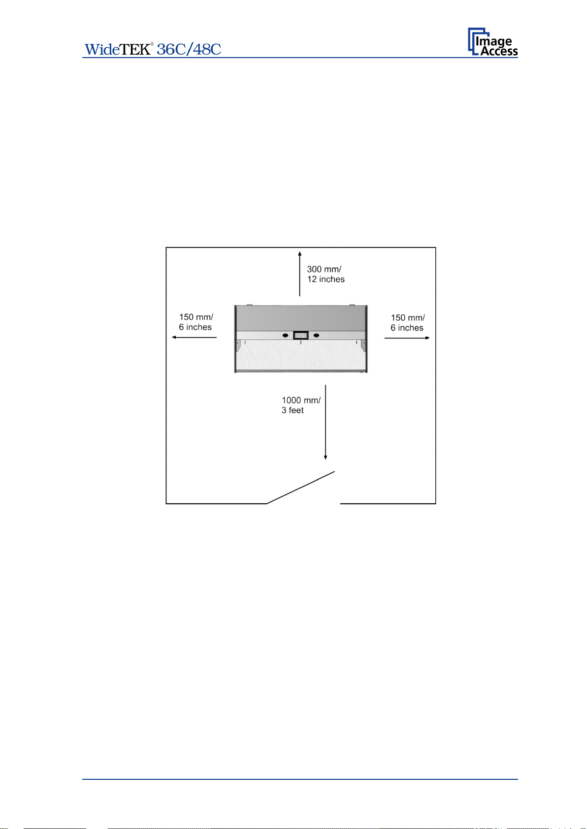
B.5 Device Location
The installation location must have
— a minimum distance of not less than 150 mm (6 inch) between the sides of the
scanner and the wall,
— a minimum distance of not less than 300 mm (12 inch) between the backside of th e
scanner and the wall,
— a minimum distance of not less than one meter (3 feet) from any door or entrance
way and the scanner.
Use illustration below as a guide.
Picture 10: Minimum distances to the scanner
Do not operate the scanner in an area that has poor air circulation, and/or that is nonventilated.
Place the scanner on a flat and solid base. The load bearing capacity of the base must
correspond to the device weight.
It is recommended to place the scanner always on the floor stand which comes with the
scanner. The floor stand gives the best ergonomic position when using the scanner.
Choose a location that complies with the limits of temperature and humidity. Refer to the
technical specification, chapter G.3.
Note: Before using the scanner in the new environment allow at least one hour for
temperature adaptation.
Temperature adaptation means:
A fast change from cold to warm environmental conditions can build up
condensation inside the housing. This will result in unfavorable scanned images
and could cause permanent damages to the unit.
Manual Page 27
Page 28

B.6 Maintenance
Important: Ensure that no liquids will penetrate into the device housing.
B.6.1 Touchscreen
Before cleaning the touchscreen, switch the scanner off and set the main power switch to
position 0.
The touchscreen can be cleaned with a micro fiber cloth.
B.6.2 Surfaces
Use a soft, dampened cloth to clean the housing of the scanner. Recommended is a micro
fiber cloth.
B.6.3 Camera Modules Glass Plates
Important: Do not use any cleanser with solvents to clean the glass plates!
The camera module glass plates have a special surface coating.
It is recommended to clean the glass plates always with a micro fiber cloth.
Dampen the micro fiber cloth slightly before cleaning.
Clean the glass plates with minimum pressure. Do not rub the glass plates on isolated
positions.
After cleaning, dry the glass plate with a soft cloth – micro fiber cloth recommended.
B.7 Repair
Note: There are not any parts or components of the WideTEK® 36C /
WideTEK® 48C scanner which can be repaired by the user.
All repairs and service works should be done by a trained technician only.
Page 28 Manual
Page 29

C Touchscreen Operation
The WideTEK® scanners can be controlled in two ways.
• Via the integrated touchscreen and its applications.
The functions of the applications available from the touchscreen are described
starting with chapter C.1.
• Via a standard browser and the integrated ScanWizard Web user interface. A short
introduction of the functions of the integrated ScanWizard user interface starts in
chapter D.
Please note: All screenshots are taken from a fully equipped device with all options
and functions activated. Depending on the selected mode, the menus
displayed on the screen can vary.
GENERAL NOTICE
This manual describes the functions of a com plete eq uipped scanner. If your device is not
equipped with all features, deviations are possible.
Manual Page 29
Page 30

Touching this button will switch to a user programmable application.
C.1 Select Application Screen
When the WideTEK® scanner starts from standby mode and finishes the startup
procedure, the touchscreen displays the Select Application screen.
Picture 11: Select application screen after start-up
Touching one of these buttons activates the Scan2Net
application.
The Easy mode differs from the Expert mode by a reduced number
of available parameters.
The description of the Scan2Net® user interface describes the Expert
mode with all parameters. See chapter C.3 and subchapters.
As factory default the EasyScan application is integrated.
To leave the application, touch a free section in the title line of the
application. Confirm the request by touching the STOP button.
Touching this button switches to the start screen of the integrated
ScanWizard application.
®
kiosk
Page 30 Manual
Page 31

Paper Feed Delay
Defines the delay between inserting the document into the
C.1.1 Document Tr a ns port Settings
Touch the icon in the upper the left corner in order to open the
document transport settings.
An additional window placed in front of the select application screen will open.
It contains a slider to set the Paper Feed Delay …
Picture 12: Document Transport Settings, part 1
… and three buttons to set Scan Mode, Transport Speed and Document Output.
Picture 13: Document Transport Settings, part 2
C.1.1.1 Paper Feed Delay
transport path and the transport start.
Manual Page 31
Page 32

Direct:
Feeds the document in the scanner until the camera recognizes the
Always Ready
The document transport start directly after the application sends the
stat command. This mode is recommended for documents with
Quick:
Transports the document into the scanner until the photo sensor in
Eject:
Transports the document out of the scanner after terminating the scan
Hold:
Holds the document after terminating the scan sequence at the output
Normal
The transport speed depends on the selected resolution. Valid is: The
Slow
Reduces the transport speed to a half of the normal speed. This mode
C.1.1.2 Scan Mode
(Default)
document edge; then the document returns to the start position.
irregular document edges.
the transport path detects the paper edge.
C.1.1.3 Document Output
sequence.
side of the transport path.
C.1.1.4 Transport Speed
higher the resolution, the slower the transport sped.
is recommended for delicate or antique documents.
Page 32 Manual
Page 33

Turns the image in clockwise direction.
Deletes the selected image. Only active in
Marks where in the list an image should be inserted.
Only active in
Moves upwards through the list of images.
Only active in
Moves downwards through the list of images.
Only
Displays the image in 100% size.
Fits the image size to the screen size. Alternates with the above
displayed icon. Available, if the image is displayed in 100%.
Marks
C.2 ScanWizard Application
ScanWizard is an int uitive user interface for your Scan2Net® scanner, which enables the
user to control the scanner and all scanning parameters by clearly structured menus.
Picture 14: ScanWizard application main screen
1: Preview section. The scanned image is displayed here as preview. The buttons
beside the preview window have the following function:
Job Mode.
Job Mode.
Job Mode.
active in Job Mode.
an imag e.
Manual Page 33
Page 34

3:
Button
Function
Touch this icon to end the job mode and to return to single
Touch this icon to transport the document forward through the
Touch this icon to transport the document reverse through the
This icon is displayed if an image has been marked in the list
2: Menu button bar. Used to select scanning parameters and in order to set the
parameters in detail.
Returns the scanner to default parameter settings.
Activates the job mode.
mode. Only active in Job Mode.
document path.
document path.
Starts the scan sequence.
for rescanning. Only active in Job Mode.
4: Status line. Shows some information of the scanner.
Touch the Scan2Net symbol to return to Select Application screen.
Page 34 Manual
Page 35

C.2.1 Size
Select here the parameters which define the resulting image size and activate special
features.
Picture 15: Menu with Size parameters
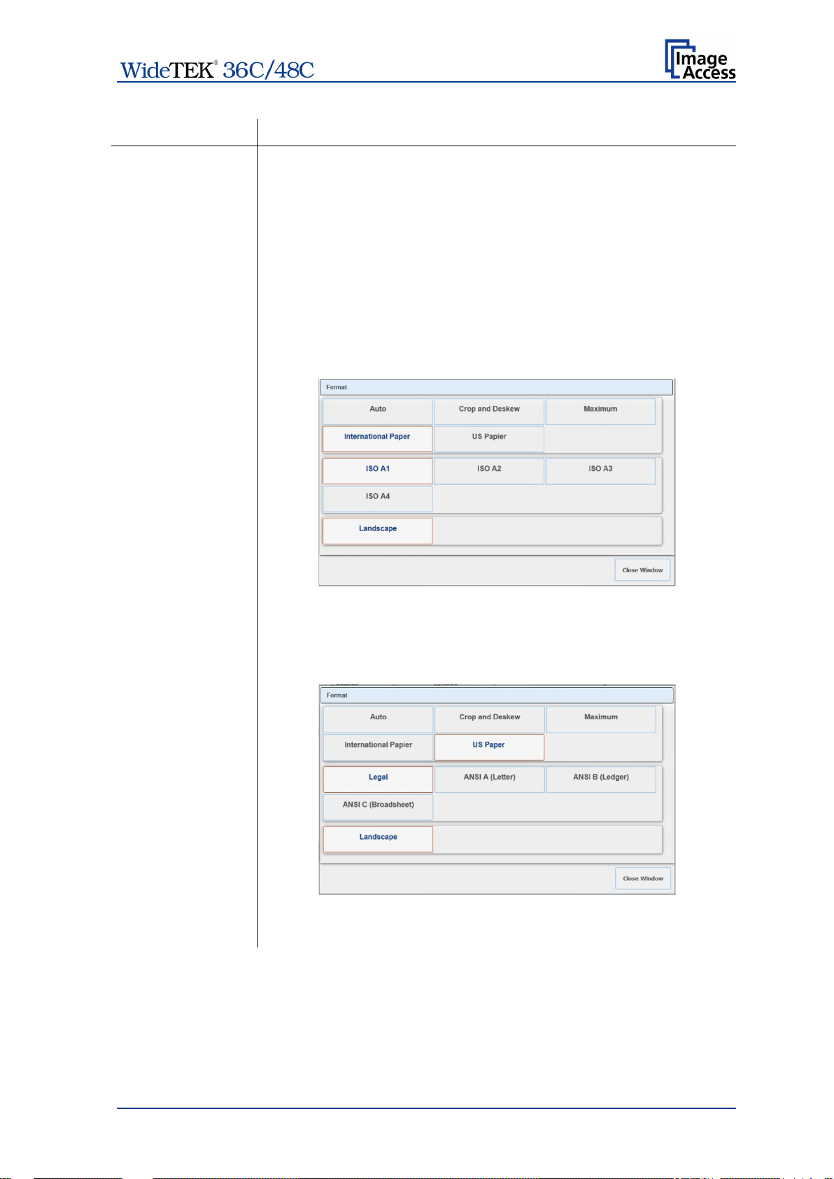
C.2.1.1 Format
Picture 16: Select document mode
Depending on the Format selected further parameters appear in the area below the
Format selector buttons.
Manual Page 35
Page 36

Format
Function
Auto
The complete scan area will be scanned.
size. If the
When scanning dark documents, the value should be reduced in
The higher the numeric value, the more contrast must be
The resulting image will be reduced to the document
document is not exactly aligned horizontally, the resulting images
will have the smallest possible black margin.
Auto Density (Binary)
small steps until the desired result is achieved.
Note:
between background and scanned document.
Document Edges
Unit of measurement
Touch the selection arrow to open the list of available parameters.
Bottom / Top / Right /Left Edge
Move the slider to set the additional edge which should ne added to
the resulting image after scanning.
Page 36 Manual
Page 37
Format
Function
Crop and Deskew
The complete scan area will be scanned.
Maximum
Landscape: Scans the maximum scan area in landscape
International
When selecting International Paper the window will be extended
US Paper
When se lecting US Paper the window will be extended and shows
The resulting image shows the document aligned and cropped to its
real size.
orientation.
Paper
and shows the available ISO (=DIN) document sizes and the
Landscape button.
All formats are positioned symmetrically to the horizontal middle of
the document input.
the available ANSI document sizes and the Landscape button.
All formats are positioned symmetrically to the horizontal middle of
the document input.
Manual Page 37
Page 38

C.2.1.2 Mirror
Picture 17: Mirror selector
Touch a button to select the mirror axis.
Using this setting can be helpful if scanning transparencies from the back.
C.2.1.3 Splitting Image
Picture 18: Splitting Image parameters
The Splitting Image function splits the scanned image symmetrically in two parts.
Left The left part of the split image will be displayed.
Right The right part of the split image will be displayed.
Auto Both parts of the split image will be displayed successively as separate
images.
Off Disables the splitting function.
C.2.1.4 Start Splitting
Picture 19: Defines the splitting function start page
Defines the start page if Splitting Image is set to Auto.
Left Sets the left part of the split image as start page.
Right Sets the right part of the split image as start page.
Page 38 Manual
Page 39

C.2.2 Quality
Select here the color parameters, set the resolution and set the scan mode.
Picture 20: Menu with Quality parameters
C.2.2.1 Color Mode
Picture 21: Available color modes
Touch the button of the desired color mode.
Depending at the selected color modes other menu items become active.
For example Binary and Enhanced Halftone activate the Invert button.
Manual Page 39
Page 40

C.2.2.2 Color Space
Picture 22: Color Space
Available are three predefined color spaces, which can be used while scanning.
Touch the button to select the color space.
Native Color space determined by the hardware (CCD camera) of the scanner.
AdobeRGB T his is an RGB color space, defined by Adobe Systems. It contains half of
the colors defined for the Lab color space.
sRGB The standard RGB (sRGB) color space is a color space with a reduced
amount of colors.
C.2.2.3 ICC Profiles
Picture 23: Activates ICC profile embedding
Touch On to activate the ICC profile for the external monitor.
C.2.2.4 Invert
Picture 24: Invert function
This setting is only available with the color modes Binary and Enhanced Halftone.
Page 40 Manual
Page 41

C.2.2.5 DPI
Picture 25: Resolutions available with the scanner
The content of the list can vary, depending on the hardware features of the scanner.
C.2.2.6 Scan Mode
Picture 26: Scan modes of the scanner
Fast Scans with normal speed. The scan speed depends on the selected
scan resolution. That means, the higher the resolution, the lower the
scan speed.
High Quality Reduces the scan speed to the half but improves the scanning
quality.
C.2.2.7 Stitching
Stitching allows selecting one of two stitching methods.
Picture 27: Available stitching methods
The default set ting is Adaptive 2D.
None: Select this setting when scanning plain documents with the paper
transport wings inserted.
Adaptive 2D Default setting.
Select this setting when scanning documents with uneven structured
surface, e.g. multiple folded papers. The image data will be merged
dynamically. The time until the image is displayed will increase a little.
Manual Page 41
Page 42

C.2.3 Enhancement
Set here the values for image enhancement.
Picture 28: Slider for Enhancement parameters
C.2.3.1 Brightness
The Brightness slider defines the resulting brightness in the image. Lower brightness
values result in darker images, higher values result in brighter images.
Values close to 0% or to 100% may result in unwanted artifacts.
Touch the slider and move it to the desired position to set the value.
Otherwise touch the buttons + (plus) or – (minus) to modify the value.
C.2.3.2 Contrast
The Contrast slider defines the contrast in the image. Lower contrast values result in
“smoother” images; higher values show more details and the images become “crisper”.
Values close to 0% or to 100% may result in unwanted artifacts.
Touch the slider and move it to the desired position to set the value.
Otherwise touch the buttons + (plus) or – (minus) to modify the value.
C.2.3.3 Image Sharpness
The Image Sharpness slider invokes an advanced automatic sharpening algorithm which
sharpens the image before any other operation is performed.
The value “zero” disables the function. Very high values may produce artifacts depending
on the type of document.
Touch the slider and move it to the desired position to set the value.
Otherwise touch the buttons + (plus) or – (minus) to modify the value.
Page 42 Manual
Page 43

C.2.3.4 Exposure
Picture 29: Exposures modes
Fixed switches the function off.
If Auto is selected, the sliders of Enhancement parameters (Picture 28) change.
Picture 30: Black / White Threshold sliders
The sliders Brightness and Contrast are not displayed.
Two sliders for Black Threshold and White Threshold are displayed instead.
Black Threshold: Sets the threshold for black. All pixel values found in the image below
the selected value are set to solid black.
White Threshold: Sets the threshold for white. All pixel values found in the image
above the selected value are set to white.
Manual Page 43
Page 44
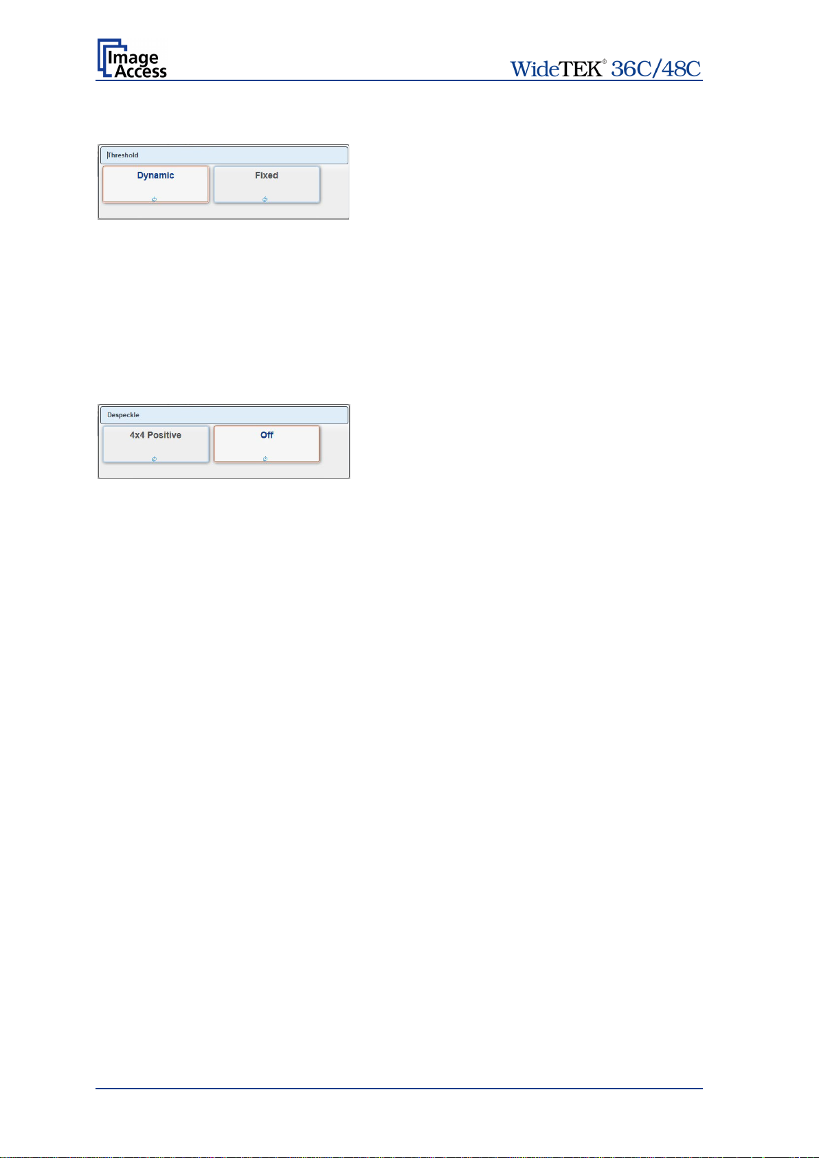
C.2.3.5 Threshold
Picture 31: Threshold selector
If color mode is set to either binary or enhanced halftone, Threshhold is selectable.
Dynamic If threshold is set to Dynamic, the result is better on low contrast
documents.
Fixed If s et to Fixed, the function is disabled.
C.2.3.6 Despeckle
Picture 32: Despeckle selector
If color mode is set to either binary or enhanced halftone, Despeckle is selectable.
When scanning in binary or enhanced halftone, speckles (small dots which are actually
extra pixels visible to the scanner) may appear on the image. Speckles can be caused by
dust, scratches or imperfections in the print of the source document.
Selecting Despeckle removes these imperfections from the scanned image.
4x4 Positive Activates the function.
Off Disables the function.
Page 44 Manual
Page 45

Paper Feed Delay
Defines the delay between inserting the document into the
Direct:
Feeds the document in the scanner until the camera recognizes the
Always Ready
The document transport start directly after the application sends the
command. This mode is recommended for documents with
Quick:
Transports the document into the scanner until the photo sensor in
C.2.4 Transport
The settings available here are similar as described in chapter C.1.1 to C.1.1.4.
Picture 33: Transport parameters
C.2.4.1 Paper Feed Delay
transport path and the transport start.
C.2.4.2 Scan Mode
(Default)
document edge; then the document returns to the start position.
start
irregular document edges.
the transport path detects the paper edge.
Manual Page 45
Page 46
Normal
The transport speed depends on the selected resolution. Valid is: The
Slow
Reduces the transport speed to a half of the normal speed. This mode
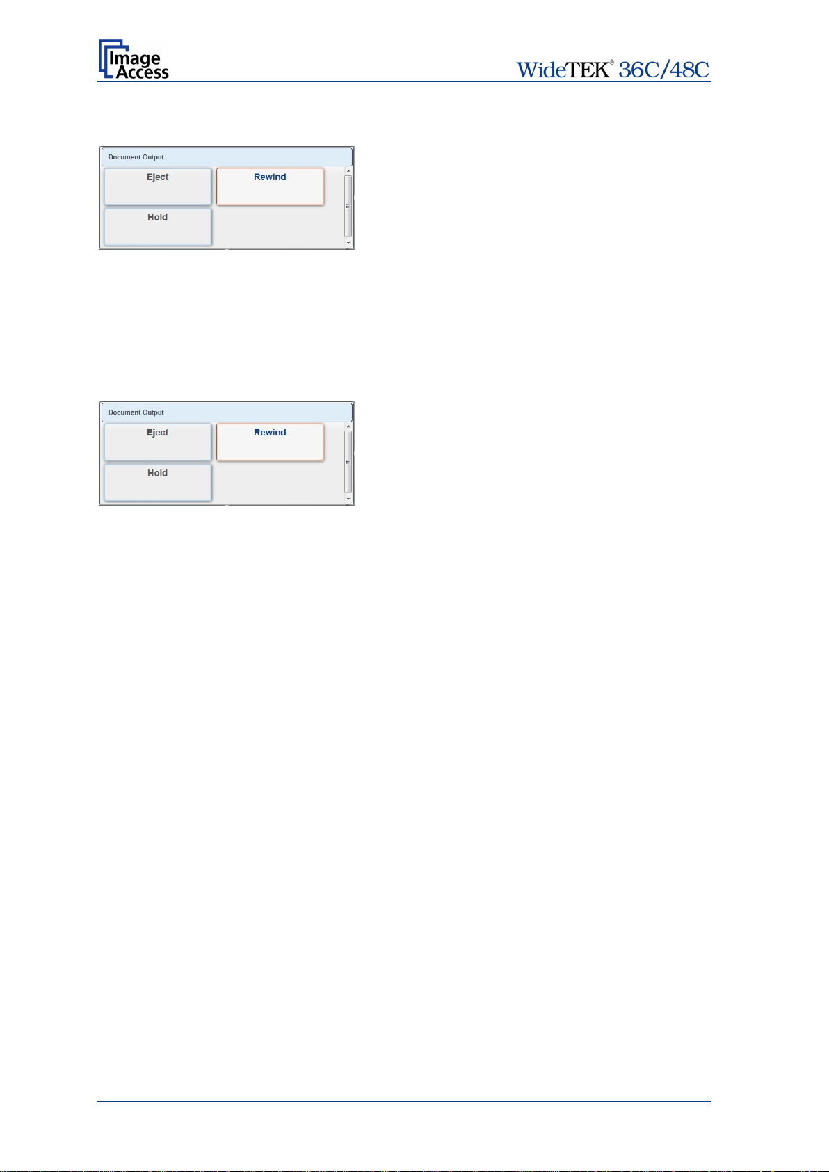
Eject:
Transports the document out of the scanner after terminating the scan
Rewind:
Returns the document to the front side after scanning.
Hold:
Holds the document after terminating the scan sequence at the output
C.2.4.3 Transport Speed
higher the resolution, the slower the transport sped.
is recommended for delicate or antique documents.
C.2.4.4 Document Output
sequence.
side of the transport path.
Page 46 Manual
Page 47

C.2.5 Transfer
Select here in the upper row the targets, whereto the image should be transferred.
In the second and third row select the parameters of the file format and all parameters
associated with the file format.
Picture 34: Transfer targets and specific file parameters
If the buttons have a blue arrow symbol in the lower left corner, touch this symbol to open
the touchscreen with the settings of the selected transfer target.
The content depends on the selected transfer target.
Chapter C.2.5.1 describes how an entry can be changed.
Manual Page 47
Page 48

Key
Function
Delete character.
Confirms changes and returns to former screen.
Cancel changes and returns to former screen.
Shift button for upper/ lower case writing.
Switches the keyboard and shows all variables which could be used in
C.2.5.1 Modifying an entry of the transfer target
To change a file name, to select a subdirectory or to modify other entries for the transfer
target, click the blue symbol. The touchscreen shows the current settings.
To change an entry, click in the respective line, for example “File name”.
The touchscreen changes and shows a keyboard. The cursor is positioned behind the
entry to be changed.
Picture 35: Keyboard, displayed on the touchscreen
the name.
Use the keyboard to modify the entry.
To confirm changes, touch the OK button.
The return to former screen without changes, touch the Cancel button.
Page 48 Manual
Page 49

Key
Function
C.2.5.2 USB
Transfers the scanned images to a USB storage device connected with the scanner.
If there is no USB storage device connected, you will see an error message otherwise the
file name and the directory will be displayed.
Picture 36: Error message if USB device is missing
If you want to change the file name, touch the line with the file name entry.
Modify the entry as described in chapter C.2.5.1.
If you want to save your image to a subdirectory on the USB storage device, click the icon
beside Directory. The directories will be listed.
Select the directory. Touch OK to confirm or touch Cancel to return without changes.
Touch here to close the window and to return to the main screen
(Picture 14).
Touch here to send the file to the selected transfer target.
Manual Page 49
Page 50

Key
Function
C.2.5.3 SMB
Touch this button in order to upload the scanned images directly to a previously defined
network drive and directory or subdirectory or to a workstation drive and directory.
Click the SMB button to see the current settings.
Picture 37: SMB pre-sets
The number of available SMB presets depends on the setting defined by the administrator
in the Poweruser setup menu.
Click at the blue arrow symbol to open the parameter list of the respective preset.
If necessary, change the entries for SMB Path and/or File Name.
Chapter C.2.5.1 describes how the entries can be modified.
Picture 38: Entries for SMB path and file name
Touch here to close the window and to return to the main screen
(Picture 14).
Touch here to send the file to the selected transfer target.
Page 50 Manual
Page 51

Key
Function
C.2.5.4 FTP
Scans directly to an FTP server.
Click the FTP button to see the current settings.
If necessary, change the entries for Upload Path and/or File Name.
Chapter C.2.5.1 describes how the entries can be modified.
Picture 39: Entries for FTP path and file name
Touch here to close the window and to return to the main screen
(Picture 14).
Touch here to send the file to the selected transfer target.
Manual Page 51
Page 52

Key
Function
C.2.5.5 Default
Scans directly to a defined directory in a cloud service.
Click the Default button to see the current settings.
All parameters can be defined form the touchscreen.
Click on the selection arrow beside the entries of Web Service and Protocol to see t he
list of available settings.
All other entries can be changed as described in chapter C.2.5.1.
Picture 40: List of cloud parameters
Touch here to close the window and to return to the main screen
(Picture 14).
Touch here to send the file to the selected transfer target.
Page 52 Manual
Page 53

Key
Function
C.2.5.6 Mail
Sends scanned images via email to a defined email recipient.
Click the Mail button to see the current settings.
The mail server information, the sender´s name, the email address and the reply-to
address can all be configured by clicking in the respective line.
Chapter C.2.5.1 describes how the entries can be modified.
Picture 41: Mail transfer settings
Touch here to close the window and to return to the main screen
(Picture 14).
Touch here to send the file to the selected transfer target.
Manual Page 53
Page 54

Key
Function
C.2.5.7 Remote Printer
Prints the images on a network printer to which the user has access.
Click the Remote Printer button to see the available pre-defined printer s ettings.
The number and names of the available printers depend on the administrator settings int
the Poweruser setup.
Picture 42: Available printers (example)
Click on a button to select a printer .
To list the settings of the selected printer, tap on the arrow symbol in the lower left corner
of the button. This opens the parameter list.
The available parameters to be modified depend on the printer.
Picture 43: List of printer parameters
Click on the selection arrow (if displayed) beside the entries to see the list of available
settings.
Touch here to close the window and to return to the main screen
(Picture 14).
Touch here to send the file to the selected transfer target.
Page 54 Manual
Page 55

C.2.5.8 File Format
Allows the user to select the file format in which scanned images are saved.
Picture 44: Select file format
Touch the button with the desired file format.
The current file format is displayed in the bottom line of the button.
C.2.5.9 Compression
Allows the user to select the compression factor used when saving the f ile in the specif ied
format. The compression factor will vary, depending on the file format selected.
If JPG is selected as file format, a list with values is displayed.
Picture 45: JPEG compression
If TIFF is selected as file format, two compression methods are available.
Picture 46: TIFF compression
Manual Page 55
Page 56

File Format
File Types
C.2.5.10 File Type
Only active if the scanner is operated in Job Mode.
The file type can vary, depending on the file format selected.
JPEG
TIFF
PNM
PDF
Page 56 Manual
Page 57

Key
Function
Touch here to close the window and to return to the main screen
C.2.5.11 PDF Document
Defines the PDF format to be used when saving scanned images as PDF file.
Picture 47: Predefined PDF settings
Touch the button with the desired setting. A list with available PDF formats will be
displayed.
Select between PDF and PDF/A format.
(Picture 14).
To list the settings, tap on the arrow symbol in the lower left corner of the button.
Available are PDF and PDF/A.
Picture 48: List of available PDF formats
Manual Page 57
Page 58

C.2.5.12 Embedded Metadata
Activates the embedding of metadata to the scanned image.
Touch the button and select On embedding metadata.
Select Off to disable the function.
C.2.5.13 OCR
Select the OCR settings here.
The number of available OCR presets depends on the setting defined by t he adm inistrator
in the Poweruser setup menu.
Currently available is the setting Default.
Page 58 Manual
Page 59

C.2.6 Job Mode in ScanWizard application
The default scan mode is Single.
Touch this icon in order to switch to Job mode
After selecting Job mode t he external TFT monitor displays an “Inf ormation Panel” at the
left margin.
Picture 49: TFT flat screen after selecting “Job mode”
The information panel contains:
Scan counter: Number of images since starting Job mode.
File size: Size of all scanned images since starting Job mode .
Free space: Available memory in percent
<Date Time>: Current date and time
Manual Page 59
Page 60

Deletes the
Marks where in the list an image should be inserted.
Moves upwards through the list of images.
Moves a selected image upwards in the list.
Moves downwards through the list of images.
Moves a selected image downwards in the list.
Selects an image from the list. A frame marks the imag e in the list of
images displayed on the TFT monitor.
If the Job Mode is active, the ScanWizard start screen changes in one detail.
Picture 50: Startscreen Job Mode
After touching Scan Now the screen shows in a separate window a disclaimer with
information about copyright and the legal situation while scanning documents.
This disclaimer must be accepted. Touch the respective button below the disclaimer text.
Picture 51: Disclaimer with copyright notes
While scanning in job mode, some icons right beside the preview section will be activated.
selected image.
Page 60 Manual
Page 61
Touch this button. An empty frame will be inserted prior to the marked
The image scanned at last is marked with a “pencil” symbol in the list on the external
monitor.
The menu button bar (Picture 14, item 2) remain the same.
C.2.6.1 Job mode, move image
Use the upwards / downwards buttons to move the blue frame at first to
the desired image.
Then touch the button. The image is marked with a red frame; the button
itself and the up-/downwards buttons are marked with a red dotted frame.
Use the upwards / downwards buttons to move the selected image to its
new position.
Press this button again to lock the image at the new position.
C.2.6.2 Job Mode, rescanning an image
Use the upwards / downwards buttons to move the blue frame to the
image which should be rescanned.
The Scan Now button changes to rescanimage.
Touch the button to start the scan sequence.
The image will be inserted at the marked position.
C.2.6.3 Job Mode, adding an image to the list at any position
Use the upwards / downwards buttons to move the blue frame to the
image where an image should be added.
Mark the image prior to the position where the image is to be inserted.
image.
Touch the button. The scanned image will be inserted at the desired
position.
Manual Page 61
Page 62

Touch the button to select the image. The image is marked with a red
Touch the button. The image will be deleted. The images, which follows
C.2.6.4 Job Mode, deleting an image
Use the upwards / downwards buttons to move the blue frame to the
image which should be deleted.
frame; the button itself and the up-/downwards buttons are marked with a
red dotted frame.
in the list, will be moved upwards.
C.2.6.5 Quit Job Mode
Touch this button in order to exit the Job Mode and to return to single
On the touchscreen a window opens.
Picture 52: Exit Job Mode request
Touch Yes to confirm the end of the Job Mode.
mode scanning.
Otherwise touch No to continue the scanning in Job Mode.
C.2.7 Return t o S ele c t Application Screen
Touch the button to leave the ScanWizard application. This will return the
touchscreen to the Select Application screen (Picture 11).
Chapter C.3 to chapter C.7 and the corresponding subchapters describe the available
functions of the Scan2Net application.
To leave the application, touch a free section in the title line of the application. Confirm the
request by touching the STOP button.
Page 62 Manual
Page 63

C.3 Scan2Net® Start Screen
In general: T he description of the Scan2Net application ref ers to the Scan2Net Expert
version.
The Scan2Net Easy version has reduced parameters.
®
Note: All screenshot s are taken from a WideTEK
of the scanner name – identical for all scanners.
After touching the Scan2Net button the Viewer&Job Control screen is displayed on the
touchscreen.
36 scanner. The content is – except
Picture 53: Viewer & Job Control screen
The touchscreen is structured in four sections, which allow operators to control and select
various functions of the scanner.
1: This section shows the main controls or parameters depending on the selected
control field in section 2.
2: Control fields to select the menu screens directly.
3: This section shows the status of the scanner, e.g. “Ready to scan, allows starting
the scan sequence by touching Scan Now, allows returning to the start screen, and
displays date and time.
4: The content of this section changes dependent on the selected control field in
section 2. More specific information can be found in the respective chapters.
Manual Page 63
Page 64

C.3.1 Touchscreen Control Fields
By touching the buttons in section 2 each menu screen can be reached directly.
The chapters C.4 to C.7 describe the functions of the menus in detail.
Touch this button to start the scan sequence.
Touch this button to return to the start screen from every other menu.
……
If available, this two arrow buttons switch to the next or to the previous menu screen.
Touch this button to return to the main menu.
Touch this button to set all parameters to default values.
Touching this button opens an additional window. The additional window contains short
information about the available functions.
C.3.2 Return t o S ele c t Application Screen
Touch the button to leave the Scan2Net application. This will return
the touchscreen to the Select Application screen (Picture 11).
Page 64 Manual
Page 65

C.4 Touchscreen – Document Source
The number of buttons and controllers in each screen can vary depending on the selected
setup. The setup can be changed by the administrator in the Poweruser menu.
The Document Source screen allows selecting from a wide range of scan parameters.
Picture 54: Document Source screen
If the content of a screen is too large to be displayed in the touchscreen completely, a
scrollbar is displayed at the right side. Touch the scrollbar and move it to see all menu
items.
The content of some menus which open after touching can vary.
C.4.1 DPI
The Resolution setting allows selecting a resolution from a list of resolution values
supported by the scanner.
Picture 55: List of Resolutions
The list can be opened by touching the blue arrow symbol beside the c urrently selected
value. Select a new resolution by touching the preferred value.
Manual Page 65
Page 66

C.4.2 Transpor t S pe e d
The Transport Speed selector allows the user to select from two speed settings.
Picture 56: Available Scan Modes
This setting determines the transport speed when feeding a document into the scanner.
Normal Transports the document with default speed; recommended for most
documents.
Slow Transports the document with reduced speed; recommended for fragile
documents, e.g. old paper or very delicate material.
Page 66 Manual
Page 67

Black Cut
Sets the threshold for black. All pixel values found in the image below
Auto
Sets the threshold for black and activates the automatic exposure
image and detects the brightest and the
darkest area. The detected brightness range is expanded to the
maximum range of the scanner. Otherwise all values below the
C.4.3 Exposure
The Exposure screen allows selecting the functions Black Cut and Auto.
Fixed switches the function off.
Picture 57: Exposure Modes
When Black Cut or Auto is selected a numeric key pad opens.
Picture 58: Numeric key pad to set threshold value
0 (zero) to 100
the selected value are set to solid black.
Result: The image contrast is improved.
0 (zero) to 100
control.
This function analyzes the
threshold are defined as “black”.
Result: Automatic contrast control and the image contrast is improved.
To set a new value, touch in the line of the displayed value and erase the value with the
DEL button.
Enter the new value with the key pad and touch Send to send the new value.
Manual Page 67
Page 68

C.4.4 Format
The Format button allows selecting the scan area size.
Depending on the Document Mode selected, the available formats will vary.
The bottom line of the button Format shows the current format setting.
Picture 59: Selector for Format settings
The following subchapters describe the available combinations of document mode and
format.
C.4.4.1 Maximum
Picture 60: Format mode Maximum
Landscape: Scans the maximum scan area in landscape orientation.
Portrait: Scans the maximum scan area in portrait orientation.
Page 68 Manual
Page 69
C.4.4.2 Auto
The complete scan area will be scanned.
Picture 61: Format mode Auto
The resulting image will be reduced to the document size. If the document is not exactly
aligned horizontally, the resulting images will have the smallest possible black margin.
The black margin depends on the size of rectangle which covers the complete document.
C.4.4.3 Crop and Deskew
The complete scan area will be scanned.
Picture 62: Format mode Crop and Deskew
The resulting image shows the document aligned and cropped to its real size.
Manual Page 69
Page 70

C.4.4.4 DIN
Picture 63: Format mode DIN
When selecting DIN, an additional small window opens.
It shows the available DIN (=ISO) document sizes as well as 25 inch and 36 inch width as
scan area dimension.
All formats are positioned symmetrically to the horizontal middle of the document input.
C.4.4.5 ANSI
Picture 64: Format mode ANSI
When selecting ANSI, an additional small window opens.
It shows the available ANSI document sizes as scan area dimension.
All formats are positioned symmetrically to the horizontal middle of the document input.
Page 70 Manual
Page 71

C.4.5 Scan Mode
The Scan Mode selector allows the user to select between two scan quality settings.
Picture 65: Scan Mode selector
In general, the scan resolution has always an impact at the scan speed.
The higher the resolution, the lower the resulting scan speeds.
Fast Scans with normal scan speed, depending from the selected resolution.
High Quality Reduces the scan speed to the half.
Manual Page 71
Page 72

C.4.6 Auto Densi ty
The Auto Density controller is used to set the scanner’s sensitivity for the automatic
format detection.
Default value: 60
Picture 66: Auto Density controller
When scanning dark documents, the value should be reduced in small steps until the
desired result is achieved.
In general: The higher the numeric value, the more contrast must be between
background and scanned document.
Page 72 Manual
Page 73

C.5 Touchscreen – I mage Quality
The Image Quality screen allows setting a wide range of image quality parameters.
Picture 67: Image Quality, screen 1
In color mode Binary, the menu will be extended by two more menu items.
Picture 68: Image Quality 2
The additional menu items are Invert and Despeckle.
See chapter C.5.8 and C.5.9
Manual Page 73
Page 74

C.5.1 Color Mode
By touching the selection arrow of the Color Mode section the list of available color
modes opens.
Picture 69: List of Color Modes
Touch the title of the desired color mode to select the mode. The list closes subsequently.
Picture 69 shows the available color modes.
C.5.2 File For m a t
Press the File Format button to select a file format for the images.
C.5.2.1 JPEG
Picture 70: Submenu File Format “jpeg”
Depending on the file format selected, some additional parameters will be displayed.
With the JPEG file format, a value for the image quality can be entered by the numeric
key pad.
This value determines the compromise between quality and compression rate. A higher
quality factor produces larger files. The default setting of 75 is a good compromise for
most documents.
Page 74 Manual
Page 75
C.5.2.2 TIFF
Picture 71: Submenu File Format TIFF
With the TIFF file format, the compression method of the file can be selected with the
TIFF Compression buttons.
CCITT G4 Recommended with color mode “Binary”.
JPEG Recommended for all other color modes.
None Disables the data compression.
C.5.2.3 PNM
With the PNM file format, no additional parameters are available.
C.5.2.4 PDF
With the PDF file format, the same compression met hods are available as with the TIFF
format (see Picture 71).
Press this button to return from a submenu to the main menu.
Manual Page 75
Page 76

C.5.3 Brightness
Picture 72: Brightness slider
The Brightness slider defines the resulting brightness in the image. Lower brightness
values result in darker images, higher values result in brighter images.
Values close to 0% or to 100% may result in unwanted artifacts.
Move the slider indicator to the desired position to set the value.
C.5.4 Contrast
Picture 73: Contrast slider
The Contrast slider defines the contrast in the image. Lower contrast values result in
“smoother” images, higher values show more details and the images become “crisper”.
Values close to 0% or to 100% may result in unwanted artifacts.
Move the slider indicator to the desired position to set the value.
C.5.5 Image Sharpness
Picture 74: Image Sharpness
The Image Sharpness slider invokes an advanced automatic sharpening algorithm which
sharpens the image before any other operation is performed.
The value “zero” disables the function. Very high values may produce artifacts depending
on the type of document.
Move the slider indicator to the desired position to set the value.
Page 76 Manual
Page 77

C.5.6 Image Rot a ti on
Picture 75: Image Rotation
The value selected from the list defines the rotation of the image in a clockwise direction.
The image will be rotated directly after scanning and before display
C.5.7 Mirror
Picture 76: Mirror
This control mirrors the image along the selected mirror axis.
Using this setting can be helpful if scanning transparencies from the back.
C.5.8 Invert
Picture 77: Invert
This control is only available with the color modes Binary and Enhanced Halftone.
If set to on, the color of the resulting image will be inverted.
C.5.9 Despeckle
Picture 78: Despeckle
This control is only available with the color modes Binary and Enhanced Halftone.
Available modes are 4x4p and Off.
Manual Page 77
Page 78

The ICC Profile checkbox is displayed when the resolution for the
scan mode is
(1)
C.6 Touchscreen – Viewer&Job Control
The Vi ewer Control screen allows the operator to control and modify the image on the
TFT flat screen.
Picture 79: Viewer & Job Control screen
The preview section (1) represents the TFT flat screen.
The scanned image is displayed on the TFT flat screen and with reduced quality in the
preview section right beside the controller elements.
Picture 80: Scanned image in preview area
scan is 300 dpi or higher or when the High Quality
active.
Page 78 Manual
Page 79

The middle circle contains the keys to
document. A centered cutout of the image is
The controller is structured in three round elements (circles).
The outer circle contains the keys to move the zoomed area
across the image.
zoom in
zoom out
rotate the image in clockwise direction in steps
of 90 degrees
scale the image to the real size of the source
displayed on the TFT flat screen.
The inner circle symbol allows selecting between two
settings. It shows the selectable setting, not the selected
setting.
Touching this symbol displays the image with its genuine
dimensions (100%), depending on the resolution selected
for scanning.
Touching this symbol displays the complete image on the
TFT flat screen. The image will be scaled to a size that
matches the screen size.
Table 1: Controller circles and their functions
Manual Page 79
Page 80

OCR button
C.6.1 Zonal OCR
The scanner offers a zonal OCR function. This function can be activated by the button
positioned right below the preview section.
Zonal OCR means, that only the marked area will be processed by the OCR function. Text
and line feed will be found only. A layout analysis will not be executed.
Prior using the zonal OCR it is required to set the scan parameters as follows:
Format: Crop and deskew
Resolution: Between 300 dpi and 600 dpi.
Note: With resolution higher than 600 dpi the OCR button will not be activated.
File format: PDF
Scan the document. The preview section of the touchscreen shows the image with
reduced resolution. After scanning, the OCR button below the preview section is active.
Picture 81: OCR button activated
Press the OCR button. The touchscreen change and shows the image and the control
buttons for the OCR function.
Picture 82: OCR touchscreen
Page 80 Manual
Page 81

Touch the image at an arbitrary position. A red rectangle will be displayed.
Picture 83: Rectangle defines the area for OCR function
Exit: Press Exit to return to the former scr een.
CUT: Press the CUT but ton. The next screen will display the defined area
more detailed.
CLR: Press CLR to delete the defined area.
OCR: Press OCR to start the OCR process.
OCR Language: Press the Up/Down arrows to select a language which is used for the
OCR process.
At first, only CUT is active.
Touch the arrows at the sides of the rectangle to define the dimension and the position of
the area where the OCR function should be executed.
This is the first step and can be understand as a “pre”-selection.
Whenever the dimensions of the rectangle have been modified, it changes the color f rom
“Red” to “Gray”.
Picture 84: Pre-selection area selected
Manual Page 81
Page 82

Press CUT to separate the previously defined area from the complete image and to
display it in detail.
Picture 85: Selected area magnified
The next screen shows the selected area magnified and allows again defining an area for
the OCR process.
Press CLR to return to the former screen and to repeat the definition of the OCR area.
Press OCR to start the OCR process.
The result of the OCR process will be displayed in the touchscreen.
Picture 86: OCR result
The OCR result shows only the plain text with line feeds, a layout analysis will not be
offered.
The text can be edited by the user with the keyboard displayed at the touchscreen.
Generate PDF: Generates the PDF file of the text, detected by the OCR analysis.
The touchscreen will return to the Viewer&Job control screen (Picture 79).
Press the Send to button to save the image together with the text as PDF file.
For more details see chapter C.7 and its subchapters.
Page 82 Manual
Page 83

C.6.2 Job Mode
The bottom line of the Viewer & Job Control screen is different to the bottom line of the
other screens.
Picture 87: Bottom line with status
The bottom line shows
• the current scan mode status,
• the button to switch the job mode between Single and Job mode
• a scan counter between the question mark symbol and the “arrow right” symbol.
The default scan mode is Single. The button shows the selectable scan mode.
After selecting Job mode the TFT f lat screen displays an “Information Panel” at the left
margin.
Picture 88: TFT flat screen after selecting “Job mode”
The information panel contains:
Scan counter: Number of images since starting Job mode.
File size: Size of all scanned images since starting Job mode .
Free space: Available memory in percent
<Date Time>: Current date and time
Manual Page 83
Page 84

When Job mode is selected, the contents of the touchscreen change.
At first a disclaimer opens, which has to be accepted.
Picture 89: Disclaimer when staring the Job mode
After accepting the disclaimer, the Viewer&Job Control screen opens.
It contains some additional control buttons above and below the preview section.
Picture 90: Job mode start screen
Page 84 Manual
Page 85

moving upwards and/or downwards through the list of images to
C.6.2.1 Navigating through the list of images
The control buttons allow navigation through the list of scanned images and image
handling while working in Job mode.
The currently scanned image is always displayed in the preview section of the
touchscreen and will be added as last image to the list displayed at the TFT flat screen.
The control buttons allow
mark an image or
After an image has been selected from the list, it is marked in the list with a red frame.
moving a selected image upwards and/or downwards to another
position,
selecting an image from the list,
adding an image at the selected position,
deleting a selected image.
The control buttons for available action will be activated, i.e. they will be displayed in full
color.
The image which was scanned last is marked with a “pencil” symbol in the list. This
symbol signalizes that the image can be modified with the functions in section
Image Quality.
The controller circles will be blanked out if another image than the last one scanned is
selected.
Picture 91: Controller circles blanked out
After selecting an image, the
Manual Page 85
button changes to
.
Page 86

Press this button to select the image. The image now can be moved with
C.6.2.2 Moving an image to another position
Use the upwards / downwards buttons to mark the image to be moved.
the upwards / downwards buttons to the new position.
Press this button again to place the image at the new position.
C.6.2.3 Adding an image at an any position to the list
Use the upwards / downwards buttons to mark the image to be moved.
This control button inserts an empty frame in the list before the selected
image.
Press the Rescan button to star t the scan sequence and to add a new
image to the list at the selected position.
C.6.2.4 Deleting an image from the list
Use the upwards / downwards buttons to mark the image to be deleted.
Use this button to select the image to be deleted.
Press this button to delete the select ed image.
C.6.2.5 Rescan an image
Use the upwards / downwards buttons to mark the image to be rescaned.
Use this button to select the image.
Press this button to rescan the image. The image will be inserted at the
selected position.
Page 86 Manual
Page 87

C.6.2.6 Finalizing the Job mode
Before finalizing the Job mode the scanned images can be transferred to different
destinations.
Picture 92: Destination to finalize Job mode
The destinations are identical to the destinations described in chapter C.7 and its
subchapters.
Before the Job mode will be finalized, a message is displayed at the touchscreen.
Confirm the message to finalize the Job mode or select No to return to the menu.
C.6.2.6.1 Job mode time out
After two minutes of inactivity the Job mode is finalized automatically.
A message box pops up and a warning sound is audible.
Picture 93: Information when time out ends
Manual Page 87
Page 88

C.7 Touchscreen – Send To
This menu provides five output options in order to store the scanned images.
Picture 94: "Send To" screen #1
Due to the dimension of the touchscr een, not all output options can be displayed at the
same time. By using the scrollbar at the right side, the content of this menu can be moved.
Move the scrollbar down to display the fifth output option on the touchscreen.
Picture 95: "Send To" screen #2
When pressing the link below the respective button, the touchscreen content changes and
displays the option screen.
The chapters C.7.2 to C.7.6 describe the options to be changed or set from the
touchscreen.
Page 88 Manual
Page 89

1
3
2
C.7.1 Changing a file name or other entries
In some of the option menus the file name can be changed.
To change the file name, touch the respective line.
The screen changes to an alphanumeric keyboard.
Picture 96: Alphanumeric keyboard
1: Use the arrow keys to position the cursor in the line.
2: Use this key to delete characters.
3: Use this button to switch between the keyboard layouts.
Ok: Touch this button to confirm the new entries and to return to the former screen.
Cancel: Touch this button to discard the new entries and to return to the former screen.
Manual Page 89
Page 90
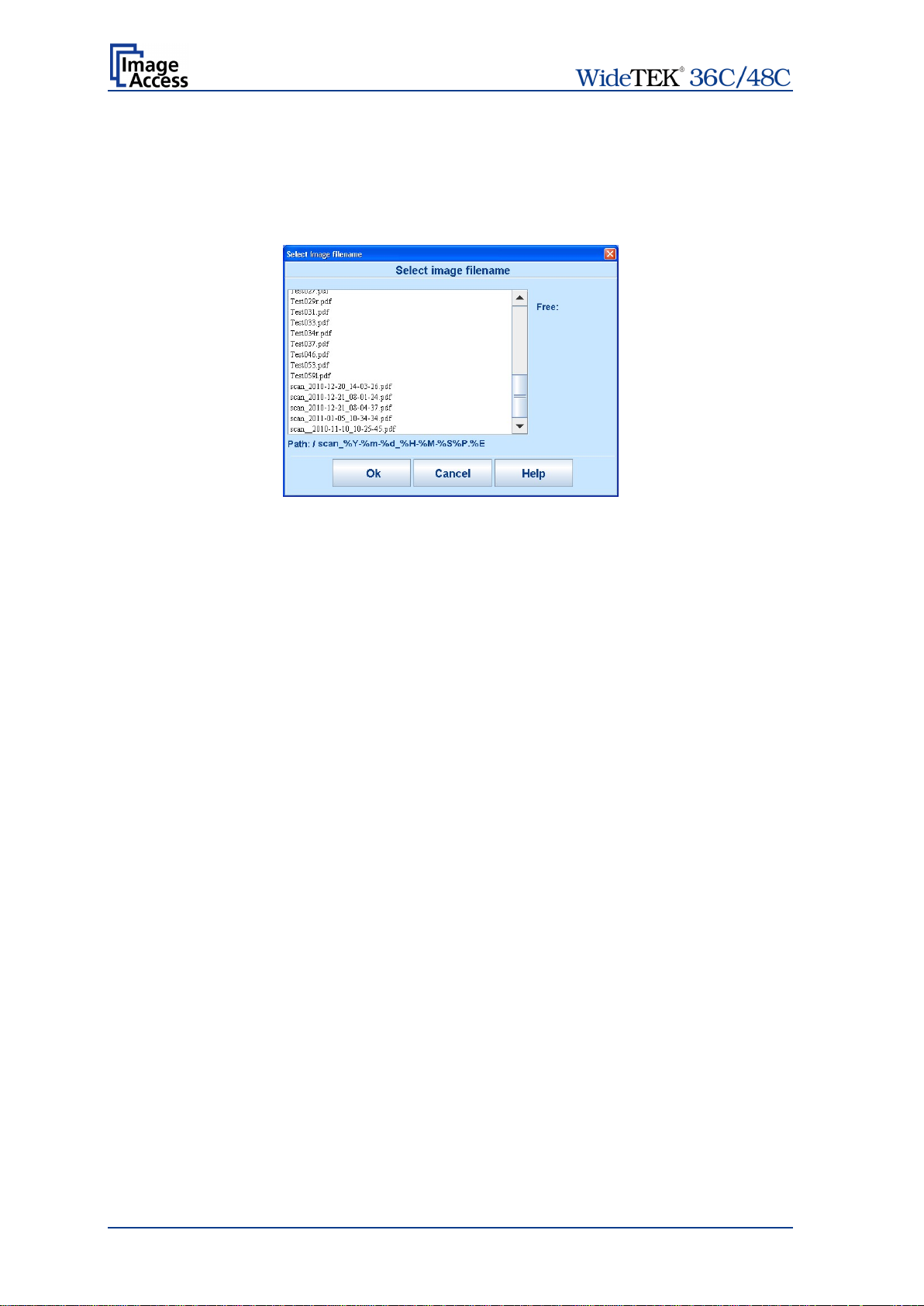
C.7.2 USB Opti ons
Two USB connectors are available at the front of the scanner to connect suitable USB
data carriers, for example USB sticks.
Touching USB Options displays the directory of a connected USB data carrier.
Picture 97: Directory of connected USB data carrier
While the directory of the USB data carrier is displayed, the LED indicator of the
respective connector is continuously illuminated.
Touch Ok or Cancel to stop displaying the directory of the USB stick.
When data is transferred between the USB data carrier and the scanner the LED indicator
blinks.
Note: When the blue indicator LED stops blinking, data transfer may still be in
progress. Before unplugging the USB media, wait a few seconds to avoid loss of
data.
C.7.2.1 List of suitable USB storage media
The criteria in the following list have been defined as a guide line for the storage media
that can be connected to the USB connectors.
• USB memory sticks,
• USB hard disks,
• USB hard disks without partition, with one or with multiple partitions,
formatted with the file systems UDF, FAT, FAT16, VFAT, FAT32, NTFS, EXT2, EXT3
or ReiserFS
The file system EXT4, BTRFS, UFS, ZFS or exFAT currently will not be supported.
Page 90 Manual
Page 91

C.7.3 Copy Options
Touch Copy Options to switch to the screen with the preset copy option configurations.
Three preset options can be stored and activated with the buttons Copy1 to Copy3.
Picture 98: Parameters of Copy Options
The parameters displayed in the above picture can only be changed from the Scan2Net®
setup interface, user level Poweruser.
C.7.3.1 Printer Settings
After pressing the button Copy image to remote printer an additional window opens.
Picture 99: Printer settings window
Here the user can select scaling of the image, the paper source and the number of copies.
The content of each line depends on the features of the connected printer.
Manual Page 91
Page 92

C.7.4 FTP Opti ons
Touch FTP Options to switch to the screen with the preset FTP server configurations.
Three preset FTP servers can be stored and activated with the buttons FTP 1 to FTP 3.
Picture 100: Parameters of FTP Options
From the touchscreen, only the entry for File Name can be changed.
To change the entry, touch the respective line.
Chapter C.7.1 describes how the entry can be changed.
All other parameters must be changed from the Scan2Net® setup interface, user level
Poweruser.
Page 92 Manual
Page 93

C.7.5 Network Options
Touch Network Options to switch to the screen showing the preset network
configurations.
Three preset configurations can be stored and activated with the buttons Network 1 to
Network 3.
Picture 101: Parameters of Network Options
From the touchscreen, only the entry for File Name can be changed.
To change the entry, touch the respective line.
Chapter C.7.1 describes how the entry can be changed.
All other parameters must be changed from the Scan2Net® setup interface, user level
Poweruser.
Manual Page 93
Page 94

C.7.6 Mail Opt ions
Touch Mail Options to switch to the screen showing the preset email configurations.
Three preset configurations can be stored and activated with the buttons Mail 1 to Mail 3.
Picture 102: Parameters of Mail Options
To change an entry, touch the respective line. From the touchscreen the values for
• Recipient
• Mail Subject
• File Name
can be changed.
Chapter C.7.1 describes how the entry can be changed.
More parameters can be changed from the Scan2Net® setup interface, user level
Poweruser.
Page 94 Manual
Page 95

C.7.6.1 Transaction modes
Two transaction modes are available for the mail transfer. The parameters for the
transaction modes can be set from the Scan2Net setup interface.
The mode, selected in the Scan2Net user interface, influences the process when a
scanned image should be mailed.
Automatic When pressing the button Mail image via SMTP at the touchscreen, the
image will be sent to the address defined in the screen Mail Options
Picture 102). The status area of the touchscreen above the Scan Now
(
button shows the message: Mail image via SMTP.
Interactive When pressing the button Mail image via SMTP at the touchscreen,
another window opens in the touchscreen. It is titled Mail Options and
allows entering another address for the recipient than the prescribed
address. All other settings remain the same.
To enter another address, click in the topmost line.
Picture 103: Interactive mode, mail options
All entered addresses will be saved in a list when Save is selected with
the checkbox. Click at the selection arrow to see the list.
Using Interactive is recommended when transferring image to often
changing addresses.
Manual Page 95
Page 96

D The User Interface S canWizard Web
Essentially, the scanner is a web server and comes with its own HTML based user
interface, named ScanWizard.
A basic requirement before working with the integrated ScanWizard user interface is to
configure the browser as follows:
• Force the br owser to reload the page content every time directly from the scanner and
not to load from the cache memory.
• Enter the scanner’s IP address in the exception list.
ScanWizard is a simple and intuitive user interface for your Scan2Net® scanner, which
can be accessed using any standard web browser. ScanWizard is operating system
independent and requires no installation of any kind on the user's client PC.
Once your network administrator has assigned the scanner an IP address and installed it
in your network, any user can access the scanner and operate it using ScanWizard.
Start your browser.
Enter the IP address which has been assigned to the scanner.
The default IP address of the scanner: 192.168.1.50
The Scan2Net® main menu will be displayed in the browser.
Picture 104: Scan2Net® main menu
Launch Scan Application switches to the ScanWizard interface. Information about the
ScanWizard interface will be found starting in chapter D.1.
Setup Device switches to the setup menu. If you have access rights to the
administrative parts of the Scan2Net® system, press this button to set up the device and
access information about the scanner. Information about the setup level User can be
found in chapter E.
Information gives a short summary of the device parameters. Information will be found
in chapter D.2.
Page 96 Manual
Page 97

D.1 The ScanWizard User Interface
After pressing the Launch Scan Application button the browser will show the
ScanWizard interface.
Picture 105: ScanWizard interface
You can bookmark the address of the ScanWizard interface in your browser for easy
access later.
ScanWizard is a function rich software which allows the user configuring and operating
the scanner easily without any additional software.
Even advanced functionality such as job management and color profiling are available in
ScanWizard.
Picture 106: ScanWizard interface layout
Using the four toolbars shown in Picture 106, the user
• selects the scanning parameters and scans,
• manipulates the images without having to rescan,
• processes large volume jobs or saves individual images to the destination of their
choice.
Manual Page 97
Page 98

D.1.1 Onli ne Hel p
These tool bars are described in detail in the online help function included in the
ScanWizard interface. Click in the “Administration” menu, item “Online Help”.
Picture 107: Online Help
D.1.2 Exit Sca nWizard
To exit the ScanWizard interface click on the main menu item “Administration”. Then click
on “Exit”.
Picture 108: “Exit” returns to Scan2Net® main menu
The browser will return to the Scan2Net® main menu (Picture 104).
Page 98 Manual
Page 99

D.2 Information
Click on the button Information in the Scan2Net® main menu (Picture 104) to get a
short summary of the device parameters.
Picture 109: Summary of device parameters
The screen is helpful if technical support is necessary. It shows e.g. the exact device type,
the installed firmware version as well as currently installed options.
Click the butto n Back to return to the start screen.
Click the button Launch Scan Application to switch to the Scan2Net® main menu
(Picture 104).
Manual Page 99
Page 100
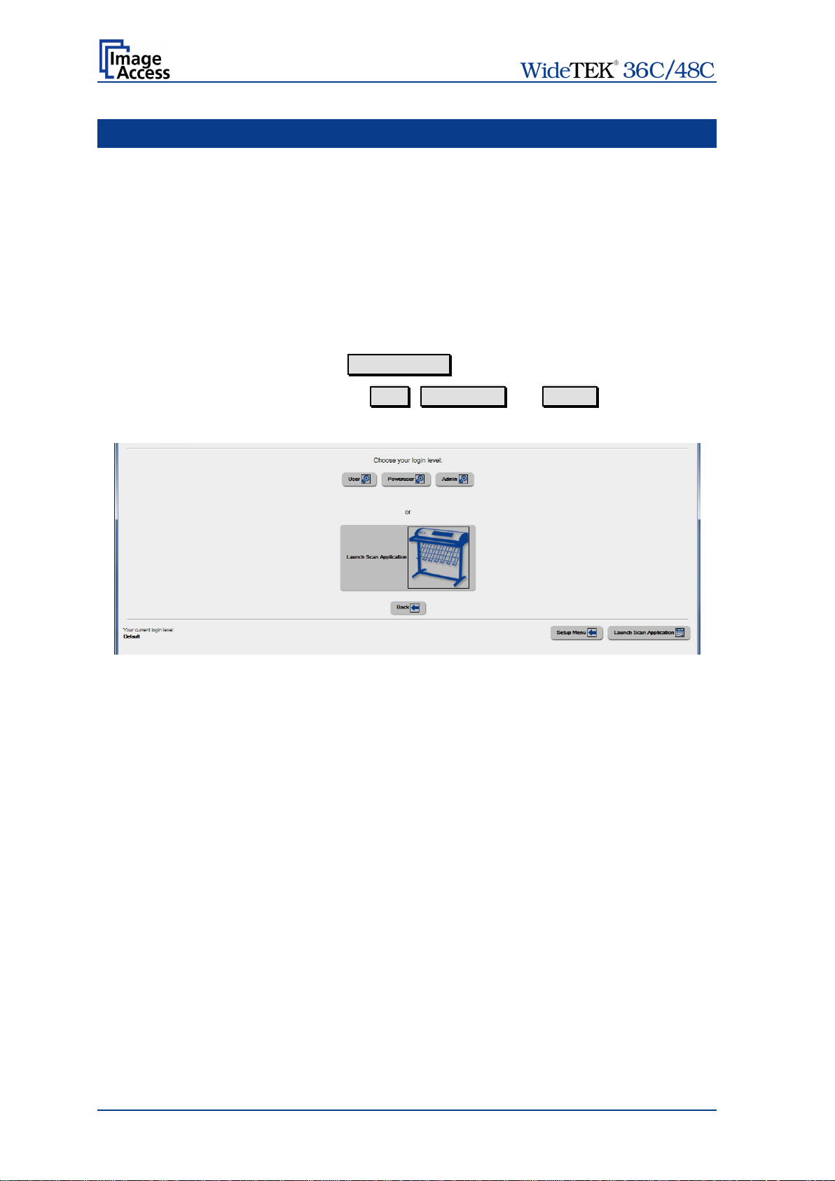
E The Setup Level
The setup level is divided in three access levels. The access levels Poweruser and
Admin are password protected.
The User access level allows showing certain information about the system like power up
time, remaining lamp life time or firmware version.
Furthermore the access level User allows setting some basic parameters.
Start your browser and enter the IP address of the scanner to get access to the scanner.
The Scan2Net® main menu will open (see Picture 104).
The Login Screen
On the start screen, click the button Setup Device .
The next screen shows the login levels User , Poweruser and Admin .
Picture 110: Login screen
Note: The login levels Poweruser and Admin are password protected.
Only trained technicians should use these levels.
Note: Further login levels can be displayed, depending at installed options.
Page 100 Manual
 Loading...