

Page 1

WideTEK® 36ART
Setup Instructions
English
09/2017
Page 2

Contents
Information about the Instructions and the Manufacturer ....................... 4
Keep Instructions with the Scanner ......................................................... 4
Design Features in Text ............................................................................ 5
Design Features in Pictures...................................................................... 5
Associated Documents ............................................................................ 6
Copyright ................................................................................................. 6
Contact Data of the Manufacturer in Germany ....................................... 7
Technical Support .................................................................................... 7
Contact Data of the Manufacturer in the U.S. ......................................... 7
Safety ........................................................................................................ 8
Intended Use ........................................................................................... 8
Basic Safety Information .......................................................................... 8
Avoiding Property Damage and Malfunctions ....................................... 10
Responsibility of the Owner .................................................................. 10
Staff Qualifications................................................................................. 10
Design Features of Warning Notices ..................................................... 11
Formatting of Information Regarding Property Damage....................... 11
Description ............................................................................................. 12
Purpose and Function ............................................................................ 12
WideTEK® 36ART Overview ................................................................... 12
Rear View ............................................................................................... 13
Setup Menu Overview Screen ............................................................... 14
Rating Plate ............................................................................................ 15
Prepare for Setup .................................................................................... 16
Connect the Power Supply .................................................................... 16
Establish the Network Connection ........................................................ 17
Switch On the Scanner ........................................................................... 18
Switch Off the Scanner .......................................................................... 20
Page 3

Perform Setup ......................................................................................... 21
Change the Menu Language .................................................................. 21
Inserting and Aligning the Scan Table ................................................... 23
Placing an Object to be Scanned on the Scan Table .............................. 24
Scanning and Watching the Object Move Through the Scanner........... 27
Preparing Whitebalance ........................................................................ 27
Activate the Setup Menu ....................................................................... 31
Perform White Balance ......................................................................... 37
Assign the IP Address ............................................................................ 45
Modify User Settings ............................................................................. 54
Set the Time and Date ........................................................................... 58
Perform Test Suite ................................................................................. 63
Technical Specifications .......................................................................... 66
Scanner Specification ............................................................................ 66
Ambient Conditions ............................................................................... 67
Electrical Data ........................................................................................ 68
Document specifications ....................................................................... 69
Dimensions and Weight ........................................................................ 69
Page 4

Information about the Instructions and the
Manufacturer
4
Information about the Instructions and the
Manufacturer
These instructions show you how to safely prepare and perform the setup
for the art scanner WideTEK® 36ART-600. The WideTEK® 36ART-600
scanners are hereinafter referred to as "Scanner".
In these instructions, the start button is called "power button".
Keep Instructions with the Scanner
These instructions are a part of the scanner.
➢ Please always store these instructions together with the scanner.
➢ Ensure that the instructions are available for the user.
➢ Enclose the instructions when you sell the scanner or transfer it in any
other way.
Page 5
Information about the Instructions and the
Manufacturer
5
Design Features in Text
Many text passages in these instructions have been formatted to indicate
specific elements, as illustrated below:
Normal text
BUTTONS OF THE SCREEN PAGE
"Menu names"
➢ Action steps
• Enumeration of the first level
Cross-references
Tips contain additional information, such as special information to
prepare for and perform the setup.
Design Features in Pictures
Where a reference is made to elements in a legend or in the text, these are
marked with a number (1).
Page 6

Information about the Instructions and the
Manufacturer
6
Associated Documents
In addition to these instructions, other documents associated with the
operation of the scanner include:
• Unpacking and Repacking Instructions
• Legal Information (Declarations of Conformity, FCC Declaration, Safety
& EMI Certificates, RoHS etc.).
Copyright
These instructions contains information that is subject to copyright. These
instructions may not be reproduced in any form, printed, filmed, edited,
copied or distributed, in whole or in part, without prior written permission
from Image Access GmbH.
© Image Access GmbH 2017
All rights reserved.
Trademarks
Scan2Net®, Scan2PAD®, Bookeye® and WideTEK® are registered
trademarks of Image Access, all other trademarks are the property of their
respective owners.
Page 7

Information about the Instructions and the
Manufacturer
7
Contact Data of the Manufacturer in Germany
Image Access GmbH
Hatzfelderstraße 161-163
42281 Wuppertal
Phone: +49-202-27058-0
E-Mail: documentation@imageaccess.de
Internet address: www.imageaccess.de
Technical Support
Image Access technical support can be reached at the e-mail address:
support@imageaccess.de.
Contact Data of the Manufacturer in the U.S.
Image Access LP
2511 Technology Drive, Suite 109
Elgin
IL 60124
Phone: +1-224-293-2585
E-Mail: support@imageaccess.us
Internet address: www.imageaccess.us
Page 8

Safety
8
Safety
Intended Use
The scanner is used for scanning fine art and other material and
documents. The fine art must comply with the characteristics described in
the technical specifications. The scanner is designed for use in enclosed
spaces in the commercial sector.
Intended use also includes observing and following all information
provided in these instructions, especially the safety instructions. Any other
use is considered to be improper and will void the warranty and liability
claims.
Ambient Conditions
Ensure that the scanner is used exclusively under the following
environmental conditions:
• Ambient temperature during operation: +5 °C to +40 °C
• Storage temperature: 0 °C to +60 °C
• Relative humidity: 20 to 80%, non-condensing
• Ambient light level between 100 and 1.000 lux
➢ Ensure that the scanner is not exposed to direct sunlight.
Basic Safety Information
Avoid Injury or Death by Electric Shock
➢ Never open the housing of the scanner.
➢ Do not expose the scanner to dripping or splashing water and do not
place any vessel filled with liquid on the scanner. Penetrating liquid can
damage the scanner.
➢ Do not insert objects through existing slots or openings into the interior
of the scanner.
Page 9

Safety
9
➢ Only connect the scanner with the plug of the supplied AC adapter to a
professionally installed and grounded outlet.
➢ Do not use the AC adapter if the power supply's housing or the cable are
damaged. In this case, replace the power supply with a power supply of
the same type.
➢ Do not use the scanner if it is visibly damaged. In this case, unplug the
power cord from the wall outlet. Contact Image Access technical
support, see section Technical Support starting at page 7.
Avoid Burns
➢ Do not cover the existing openings in the scanner housing. They serve to
ventilate. Covering the openings could cause overheating.
➢ Do not place the scanner in front of air conditioning units, which
produce high heat.
Avoid Fractures, Contusions and Bruises
Incorrect installation of the cables can cause tripping.
➢ Lay the connecting cables so that no one can trip over them.
The scanner weighs 160 kg.
➢ Only carry the scanner with a second person and a floor jack. Follow the
"Unpacking and Repacking Instructions".
➢ Place the scanner only on a stable, vibration free floor.
➢ Make sure that the scanner is leveled, as described in the "Assembly
Instructions".
Page 10

Safety
10
Avoiding Property Damage and Malfunctions
➢ Ensure adequate ventilation to comply with the environmental
conditions.
➢ Do not place the scanner in the vicinity of devices that emit strong
electromagnetic radiation.
➢ Do not lean on the scanner.
➢ Ensure that the thickness of the original to be scanned does not exceed
the current clearance between 100 and 200 mm.
➢ Do not use any cleaning agents containing abrasive additives, solvents
or acids. Use a damp microfiber cloth.
➢ Operate the touchscreen only with your finger. Other objects can
damage the touchscreen.
Responsibility of the Owner
The scanner owner must ensure that only qualified personnel carry out the
setup of the scanner.
Staff Qualifications
The staff that carries out the setup of the scanner must have knowledge in
installing, connecting and putting computer accessories into operation.
Page 11
Safety
11
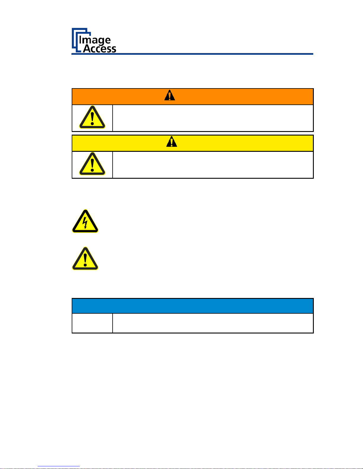
Design Features of Warning Notices
In these instructions, the following warning information can be found:
WARNING
Notices with the word WARNING warn about a dangerous
situation that could lead to death or serious injuries.
CAUTION
Notices with the word CAUTION warn about a situation that
could lead to light or medium-scale injuries.
The following symbols are used in the warnings:
Symbol
Explanation
Danger from electrical shock
General danger symbol
Formatting of Information Regarding Property Damage
ATTENTION!
These notices warn of situations that can lead to property
damage.
Page 12
Description
12
Description
Purpose and Function
The scanner is used for scanning fine art and other objects as well as
documents of all kind. It is designed for use in enclosed spaces in the
commercial sector. The originals must conform to the characteristics
according to the technical data. The scanner is designed for indoor use in
commercial areas.
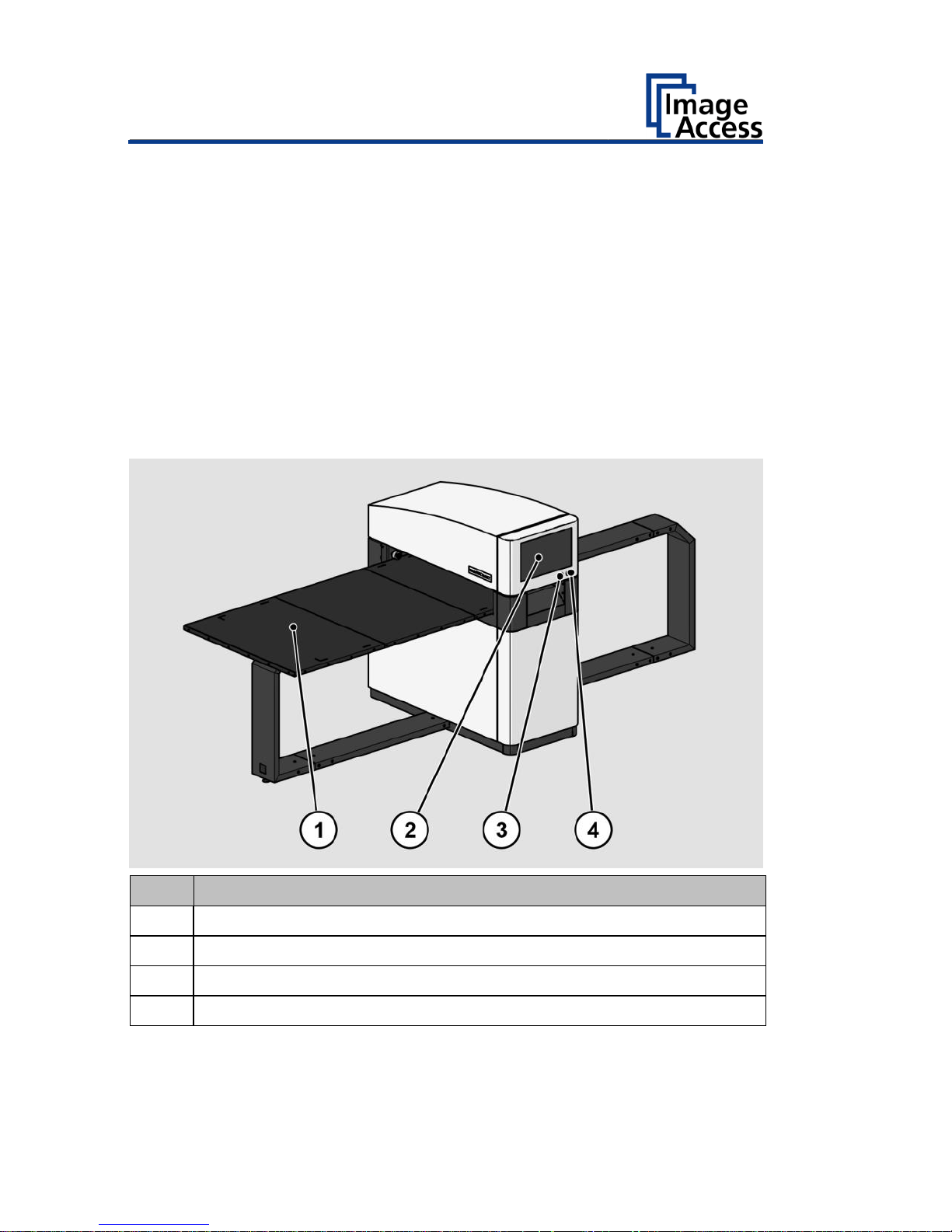
WideTEK® 36ART Overview
No.
Name
1
Scan table
2
Touchscreen
3
USB connector
4
Power button
Page 13
Description
13
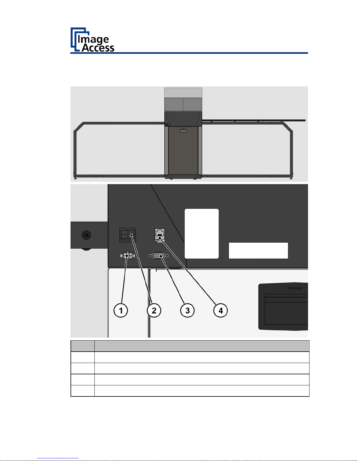
Rear View
The following diagram shows the rear view of the WideTEK® 36ART model.
No.
Name
1
24 Vdc connector for external power supply
2
Main switch
3
Recovery key connector
4
Network connector
Page 14
Description
14
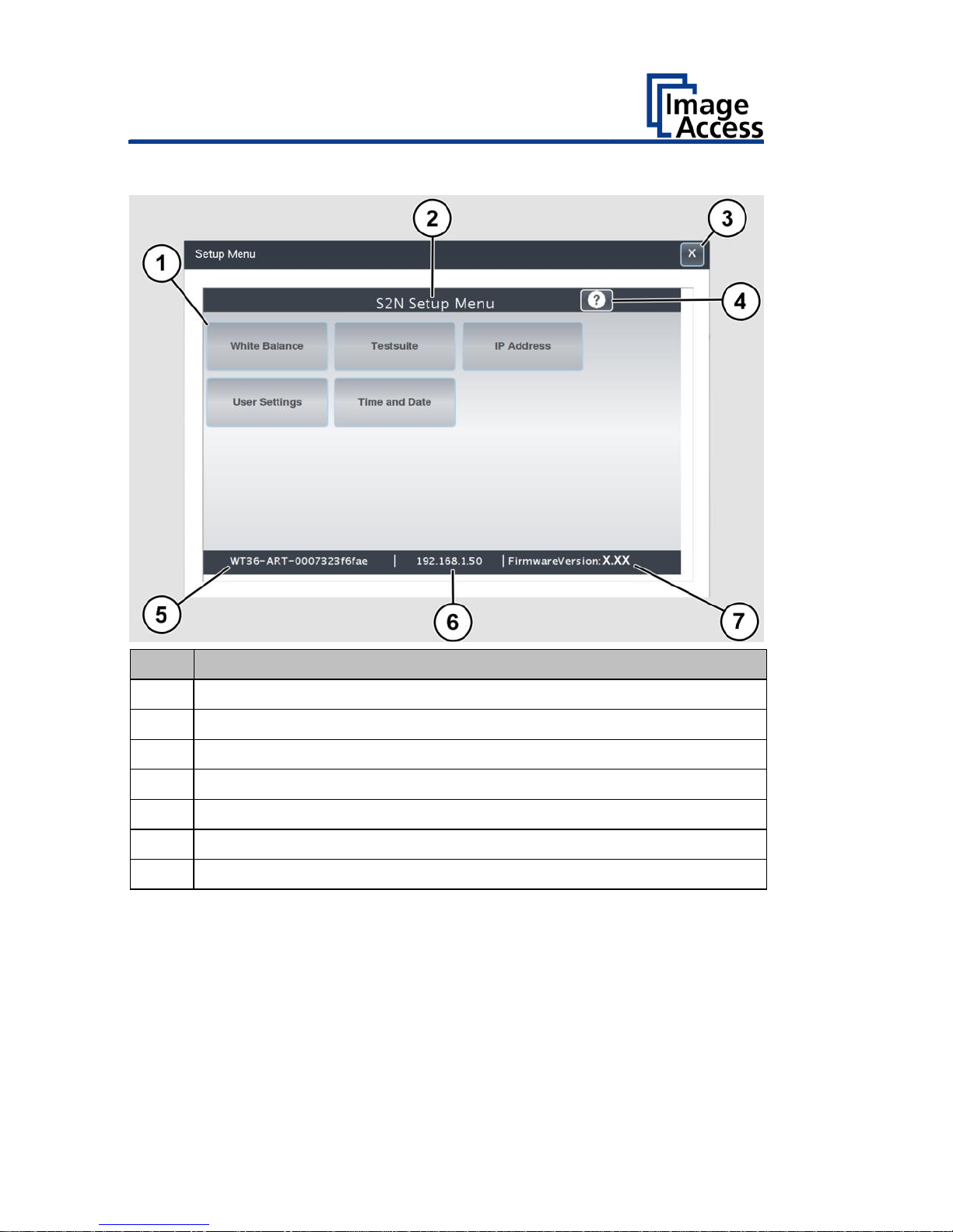
Setup Menu Overview Screen
No.
Name
1
Buttons and parameters
2
Menu name
3
Button to leave the setup menu to the start screen
4
Display the online help
5
Serial number
6
IP address
7
Firmware version
Page 15

Description
15
Rating Plate
The rating plate is attached to the back of the scanner.
The following figure shows the WideTEK® 36ART rating plate.
Page 16
Prepare for Setup
16
Prepare for Setup
Connect the Power Supply
WARNING
Risk of electric shock due to incorrect connection.
➢ Ensure that the power receptacle intended for the
connection is properly grounded.
➢ Ensure that the power receptacle intended for the
connection of the scanner is properly fused.
CAUTION
Incorrect laying of the connection cables can cause tripping.
Fractures, contusions and bruises can be the result.
➢ Place the connecting cables so that nobody can trip over
them.
To connect the power supply, proceed as follows:
➢ Make sure that the main switch of the scanner is switched off (0
position).
➢ Use only the AC adapter and power cord supplied.
➢ Ensure the power cord is not damaged.
➢ Connect the connector from the power supply to the associated 24 Vdc
connector on the back of the scanner.
➢ If not already done, connect the supplied power cable to the associated
connector on the power supply.
➢ Connect the power plug of the power supply to a power receptacle of
the correct voltage (100-240 Vac).
Page 17

Prepare for Setup
17
Establish the Network Connection
CAUTION
Incorrect laying of the connection cables can cause tripping.
Fractures, contusions and bruises can be the result.
➢ Place the connecting cables so that nobody can trip over
them.
To establish the network connection, proceed as follows:
➢ Connect one plug of the enclosed network cable to the network
connector socket on the back of the scanner.
➢ Connect the second plug to the network socket of an existing network.
Page 18
Prepare for Setup
18
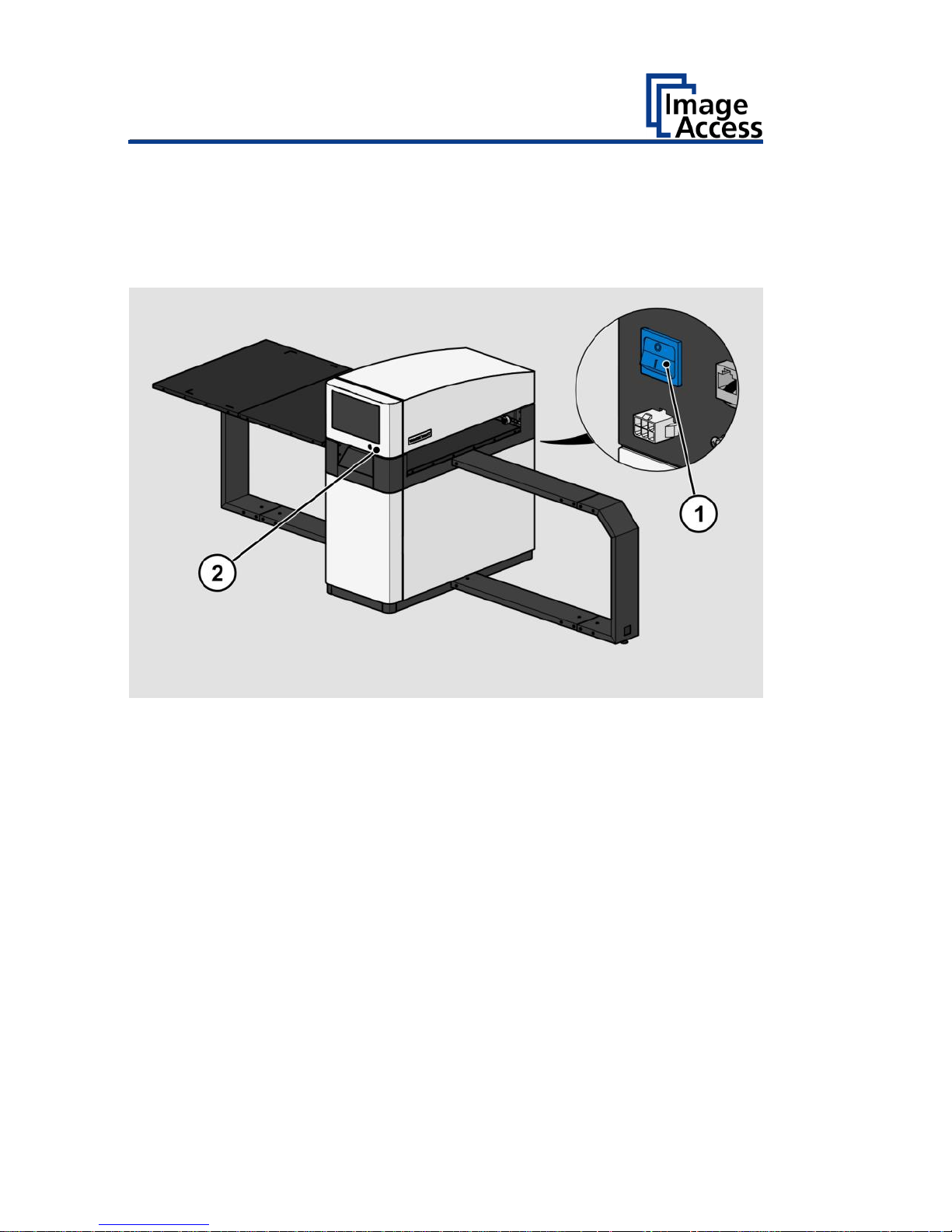
Switch On the Scanner
To switch on the scanner, proceed as follows:
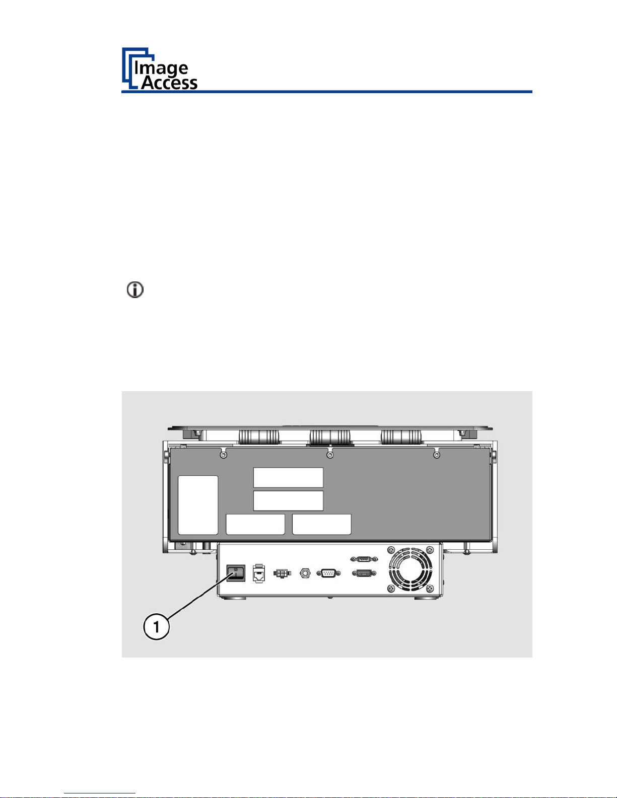
➢ Press the MAIN SWITCH (1) on the back to the "I" position.
The following diagram shows the scanner model WideTEK® 36ART.
To start the scanner from standby mode, proceed as follows:
➢ Touch the green illuminated power button (2).
The power button lights up in blue.
The scanner performs a system test.
Page 19

Prepare for Setup
19
After a short wait, the "ScanWizard Start screen" is displayed in English.
Page 20
Prepare for Setup
20
Switch Off the Scanner
To switch the scanner to standby mode after performing the setup,
proceed as follows:
➢ Touch the blue illuminated power button (2) and confirm the action in
the dialog on the touchscreen.
The scanner shuts down. This process can take up to 40 seconds.
The power button lights up green. The scanner is in standby mode.
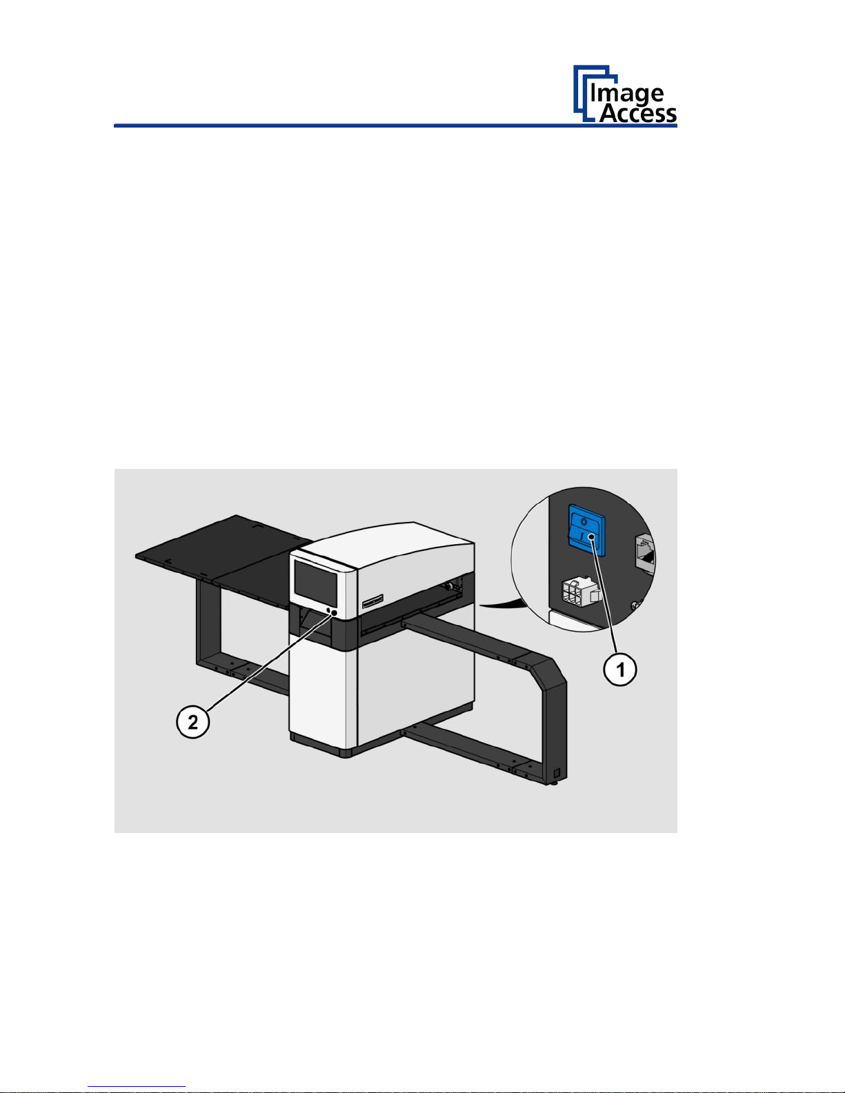
To switch off the scanner for longer periods, proceed as follows:
➢ Make sure that the scanner is in standby mode.
The power button is illuminated in green.
➢ Press the MAIN SWITCH (1) in the "0" position.
The following diagram shows the scanner model WideTEK® 36ART.
To switch off the scanner using a hard shutdown, proceed as follows:
➢ Press and hold the power button for longer than four seconds.
The power supply to the scanner is immediately interrupted.
The power button is illuminated in green.
➢ Press the MAIN SWITCH (1) in the "0" position.
Page 21

Perform Setup
21
Perform Setup
Change the Menu Language
To change the menu language, proceed as follows:
➢ Tap the LANGUAGE (1) button.
Page 22

Perform Setup
22
A window for selecting the language appears.
➢ Tap the desired language.
The window for selecting the language is closed. The "Start screen" is
displayed.
Page 23

Perform Setup
23
Inserting and Aligning the Scan Table
The scan table of the WideTEK 36ART, which holds the objects to be
scanned, can be inserted and moved on the scanner by hand.
The scan table rests on the runways and the start position is on the left
side.
The right side of the scan table goes in first and is identified by two
additional white lines across the shorter edge of the table.
➢ Place the scan table on the table holders with the longest distance to
the table’s edge from the white corner markers going in first.
➢ When the scan table has been placed on the runway, make sure that it
is flush with the right side of the scanner stand.
➢ Make sure the table is not skewed by moving the left end front and back
until the right side is flush and straight with respect to the stand.
➢ To see if it is straight, stand in front of the scanner at the right side and
look at how the top edge of the scan table runs alongside the right side
of the scanner.
The only physical connection of the table to the scanner are the
transport drums and the four pressure rollers. They move the table
with limited friction, which is a security feature. The four pressure
wheels can be adjusted by unscrewing the center bolt with the SW4
Allen wrench. The pressure wheels should apply a fair amount of
pressure to insure friction and should not be freewheeling in any
position. There is also no position switch which would tell the scanner
where the start position is. The start position is the position the
scanner table is in when a scan command is invoked. If the scan table
reaches its end, or if the scan is interrupted, press the “START
POSITION” button to return the table back to the start position.
Page 24

Perform Setup
24
Placing an Object to be Scanned on the Scan Table
➢ Place the object to be scanned on the table so that it is below the red
laser lines.
Depending on the size of the material to be scanned, either both laser lines
should be fully on the object or if the object is smaller, one laser line
should be fully on the object and the other laser line must be fully off the
object. The laser lines should not be partially on an edge of the object but
rather either both fully on the object or one fully on and one fully off.
Scanning starts at the white edge lines so the object must be placed inside
these lines but it can be placed lower than the lines, as required.
Ensure that the weight of the original to be scanned does not exceed
10 kg / 22 lb..
The default scan length is 20 inches from the edge lines. This can be
adjusted in the software and raised increments of 10 inches up to the
maximum scan length of 60 inches.
Adjusting the Camera Position
➢ In ScanWizard, tap on the CONTROL PANEL button (1).
Page 25

Perform Setup
25
➢ The WideTEK 36ART Control Panel window appears.
Camera Position Control
Button
Name
UP END
UP STOP
DOWN
DOWN END
BASE POSITION
Page 26

Perform Setup
26
1.Drive the camera to the base position.
2.Drive the camera up using the ▲ button until the right laser focus
position is found.
3.Drive the camera up until the right camera position is found.
1. Camera height in
base position
2. Laser focus in right
position
3. Camera height in
correct position
➢ Finally drive, or move, the scan table back to its start position.
Table Position Control
Button
Name
LAST SCAN START POSITION
LEFT
STOP
RIGHT
➢ Change to the ScanWizard application to select scan parameters and to
start a scan.
Page 27

Perform Setup
27
Scanning and Watching the Object Move Through the
Scanner
When the scan has been started, the operator can observe how the object
moves under the illumination line and the image is scanned line by line as
the object moves through the scanner.
When the object has passed through the illumination line, the scan is
complete and can be stopped by pressing the stop button.
In order to avoid unnecessary adjustments to the scan table, it is
recommended that you observe the object you are scanning as it passes
through the scanner and clears the illumination line, stopping the scan
when it has cleared.
Preparing Whitebalance
➢ In ScanWizard, tap on the CONTROL PANEL button (1).
Page 28

Perform Setup
28
➢ The WideTEK 36ART Control Panel window appears.
Page 29

Perform Setup
29
➢ Drive the camera in its start position, using the BASE POSITION button
(1).
➢ Drive the scan table in its start position, using the ◄ and ► buttons,
so that the top edge of the scan table runs alongside the right side of
the scanner.
➢ Place the white balance target in a straight horizontal position on the
table, so that the top edges of the target lay below the beginning of the
transport drums.
➢ Wipe over the target carefully with your hand to ensure a flat surface.
Page 30

Perform Setup
30
➢ After the White Reference Target WT36C-Z-01-A has been placed in
front of the pressure rollers, manually move the scanning table carefully
to the point where the middle of the black line is flush to the left side of
the scanner.
✓ The image below shows the white balance target in its correct
start position.
The same procedure applies to adjusting the stitching using the Stitching
Target WT36C-Z-02-A. The stitching can only be adjusted through a web
browser, running on a PC in the Power User level.
Page 31

Perform Setup
31
Activate the Setup Menu
To activate the setup menu, you have to log in on the scanner. Proceed as
follows:
➢ Tap the USER DEFAULT button (1).
The User Login window appears.
Page 32

Perform Setup
32
➢ In the User Login window, select the user Poweruser.
➢ To enter the credentials, tap with your finger on the "Password" input
field.
➢ Activate the "Show" box to see the password while entering it.
Page 33

Perform Setup
33
The screen keyboard is displayed.
➢ Enter the word "Poweruser" in the field "Password" (2).
➢ Please note that the input is case sensitive.
➢ To complete the password entry, press OK (1).
Page 34

Perform Setup
34
The User Login window appears.
➢ To complete the log in, press USER LOGIN.
Page 35

Perform Setup
35
The ScanWizard window appears.
➢ To start the Setup Menu, press the button SETUP MENU (1).
Page 36

Perform Setup
36
The "Setup Menu" screen is displayed.
White Balance:
Display the "White Balance" submenu
Testsuite:
Display the "Test Suite" submenu
IP Address:
Display the "IP Address" submenu
User Settings:
Display the "User Settings" submenu
Time and Date:
Display the "Time and Date" submenu
➢ To select a submenu from the "S2N Setup menu" screen, tap with your
finger on the button of the screen.
Page 37

Perform Setup
37
Perform White Balance
➢ On the "Setup Menu" screen, tap on WHITE BALANCE (1).
Page 38

Perform Setup
38
The "White Balance" screen is displayed.
Calibrate:
Start white balance
Delete White
Balance Data:
Delete existing white balance data
The white balance is used to ensure the quality of the scan results. The
white balance will be carried out using a test target. The test target is
marked as follows:
• WT36C-Z-01-A for WideTEK® 36
Page 39

Perform Setup
39
ATTENTION!
Impairment of the scan quality can occur if an improper
test target for the white balance is used.
➢ Make sure that the test target is free from wrinkles,
discolorations, cracks or other damage.
➢ Store the test target for the white balance in a safe place
protected from daylight.
To perform the white balance, proceed as follows:
➢ Check the position of the supplied test target (1) on the scan table as
illustrated below (2).
Page 40

Perform Setup
40
➢ Tap on CALIBRATE (1).
Page 41

Perform Setup
41
➢ Tap on NEXT STEP (1).
Page 42

Perform Setup
42
The white balance starts and the calibration is performed. During the white
balance, a rotating icon appears. The test target is transported forward and
returned. The entire white balance sequence takes about 50 seconds.
Then, the white balance result is displayed as shown in the example below.
Page 43

Perform Setup
43
On an error-free white balance calibration, the result is displayed in
green.
An incorrect result is displayed in red. If this is the case, the white
balance starts over again.
➢ To perform the white balance again, tap NEW VALUES (2).
➢ To return to the previous submenu, tap BACK (1).
Page 44

Perform Setup
44
➢ To delete the stored data of the white balance calibration, tap DELETE
WHITE BALANCE DATA (2).
➢ After deleting the stored data, run the white balance again, as
described.
➢ If problems arise during the white balance calibration, contact Image
Access technical support, see section Technical Support starting at page
7.
➢ To return to the previous submenu, tap BACK (1).
After a successful white balance, proceed as follows:
➢ Remove the test target.
➢ Store the test target in a place which is protected from daylight.
➢ Ensure that the test target is not damaged, bent or soiled.
Page 45

Perform Setup
45
Assign the IP Address
Manually Assign the IP Address
To manually assign the IP address, proceed as follows:
➢ On the "Setup Menu" screen, tap on IP Address (1).
Page 46

Perform Setup
46
The "IP Address" screen is displayed.
Set network
settings:
Accept the network settings provided
Reset to Factory:
Reset to factory settings
IP Address:
Input field for the IP address
Subnet Mask:
Input field for data on the subnet mask
Gateway:
Input field for the gateway address
IP Configuration
Method
Manual/DHCP:
Assign an IP address manually or automatically
Page 47

Perform Setup
47
➢ Tap the "IP Address" (1) field.
Page 48

Perform Setup
48
The "IP Address" window is displayed.
➢ Enter the IP address (1).
Page 49

Perform Setup
49
➢ To delete a digit, move the cursor to the right, behind the digit to be
deleted and tap DEL (1).
Page 50

Perform Setup
50
The arrow keys left (1) and right (2) next to the number "0" move the
cursor within the chosen row.
➢ To complete the entry, press OK (3).
➢ Perform the settings for gateway and subnet mask in the same way.
Page 51

Perform Setup
51
➢ To save the network settings, tap SET NETWORK SETTINGS (2).
➢ To return to the previous submenu, tap BACK (1).
Page 52

Perform Setup
52
Automatically Assign the IP Address
To automatically assign the IP address, proceed as follows:
➢ On the "Setup Menu" screen, tap on IP Address (1).
Page 53

Perform Setup
53
➢ In the selection menu "IP Configuration Method", select the "DHCP" (2)
entry.
➢ To return to the previous submenu, tap BACK (1).
Page 54

Perform Setup
54
Modify User Settings
➢ On the "Setup Menu" screen, tap on USER SETTINGS (1).
Page 55

Perform Setup
55
The "User Settings" screen is displayed.
Default:
The scanner default settings will be established
again
Language:
Select language
Display standby
after:
Define the period of inactivity, until an optional
external monitor and the touchscreen switch to
the standby mode
Screen Saver after:
The period of inactivity is defined until the screen
saver is activated
Device standby
after:
The period of inactivity is defined until the scanner
goes into standby mode
Page 56

Perform Setup
56
Select Language
To select the language, proceed as follows:
➢ Tap the on the selection arrow of the selection menu "Language" to
display the list of languages.
➢ Tap the desired language (2).
➢ To return to the previous submenu, tap BACK (1).
Page 57

Perform Setup
57
Set Standby Times
To set the standby times, proceed as follows:
➢ Tap the selection arrow of the selection menu.
➢ Tap on the desired entry (2).
➢ Perform the settings for the screen saver and the device standby in the
same way.
➢ To return to the previous submenu, tap BACK (1).
➢ To return to the "Start screen", tap EXIT (3).
Page 58

Perform Setup
58
Set the Time and Date
➢ On the "Setup Menu" screen, tap on TIME and DATE (1).
Page 59

Perform Setup
59
The screen "Time and Date" appears.
Enter new time:
Enter hours and minutes with the arrow keys
Enter new date:
Open a calendar to set the date
Store time and
date:
Accept the set values
Time Zone:
Select a time zone
Page 60

Perform Setup
60
To set the time, proceed as follows:
➢ Tap the "Enter new time" field.
➢ To set the time later, tap the up arrow (2).
➢ To set the time earlier, tap the down arrow (2).
➢ To save the modified time, click STORE TIME AND DATE (3).
➢ To return to the previous submenu, tap BACK (1).
Page 61

Perform Setup
61
To set the date, proceed as follows:
➢ Tap the "Enter new date" field.
A calendar (3) is displayed.
➢ Select the appropriate date in the calendar (3).
➢ To set the month and year, tap the arrow keys (2, 4) at the top of the
calendar.
➢ To set the day, tap the corresponding day in the calendar.
➢ To save the date, click STORE TIME AND DATE (5).
➢ To return to the previous submenu, tap BACK (1).
Page 62

Perform Setup
62
➢ To select the time zone, tap the selection arrow (3).
A selection list with available time zones is displayed.
➢ Select the appropriate time zone.
➢ To save the time zone, click STORE TIME AND DATE (2).
➢ To return to the previous submenu, tap BACK (1).
Page 63

Perform Setup
63
Perform Test Suite
➢ On the "Setup Menu" screen, tap on TESTSUITE (1).
Page 64

Perform Setup
64
The "Testsuite" screen is displayed.
Information about
the mainboard:
Display the current values for:
Temperature of PCB and CPU cores, fan speed,
PCB voltages
Information about
the inputs:
Inputs will always appear green
Information on end
position switches:
When the end position switches are activated, the
display changes from green to red, for as long as
the switches are activated
Information about
LED lamps and
lasers:
Check function: Lamp 1, Lamp 2, Laser Check, Off
Page 65

Perform Setup
65
Test the LED Lamps Functionality
➢ To check whether both LED lamps working properly, select from the
"Lamp" menu the entry "Lamp 1" and "Lamp 2" one after the other (2).
The LED lamps are illuminated.
➢ To return to the previous submenu, tap BACK (1).
Test the Laser Functionality
➢ To check whether the LED lamps work properly, select from the "Lamp"
menu the entry "Laser check" (2).
The Lasers are illuminated.
➢ To return to the previous submenu, tap BACK (1).
Page 66

Technical Specifications
66
Technical Specifications
Scanner Specification
Optical System
Maximum document size
914 x 1524 mm / 36 x 60 in
Scan width
915 mm / 36 in
Scanner resolution
600 × 600 dpi
Optical resolution
600 × 600 dpi
Pixel size
9,3 × 9,3 μm
Sensor type
3 x Tri-color line sensor CCDs
Color depth
16 bit grayscale (internal
resolution)
48 bit color (internal resolution)
Sensor resolution
67.500 pixels (3 x 22.500)
Scan modes
24 bit color, 8 bit color indexed,
8 bit grayscale, bitonal, halftone
File formats
Multipage PDF (PDF/A) and TIFF,
JPEG, JPEG 2000, PNM, PNG, BMP,
TIFF (Raw, G3, G4, LZW, JPEG),
AutoCAD DWF, JBIG, DjVu, DICOM,
PCX, Postscript, EPS, Raw data
Illumination
Light source
Two lamps with white LEDs,
integrated optical diffusor
Intensity
3000 lux maximum
Temperature induced change
None
UV / IR radiation
None
Lifetime of the LEDs
50,000 hours (typically)
Page 67

Technical Specifications
67
Ambient Conditions
Ambient temperature during
operation
+5 to +40 °C
Storage temperature
0 to +60 °C
Relative humidity
20 to 80% (non-condensing)
Noise development
≤ 35 dB(A) (Scanning)
≤ 25 dB(A) (Standby)
Page 68

Technical Specifications
68
Electrical Data
External Power Supply
Input voltage
100–240 Vac
Frequency
47–63 Hz
Output voltage
24 Vdc
Output current
6,25 A
ECO Standard
CEC Level VI
Scanner
Input voltage
24 Vdc
Input current (non fused)
max. 5 A
Power consumption
Sleep mode
≤ 0,5 W
Standby mode
ca. 5,2 W
Ready to scan
< 50 W
Scanning
< 95 W
Page 69

Technical Specifications
69
Document specifications
Maximum scan heights
100 mm / 4 in
Document thickness
200 mm / 8 in1
Maximum permissible document
weight
10 kg
22 lb.
1
(E.g. Canvas up to max. 100 mm in a frame up to 200 mm thickness).
Dimensions and Weight
Scanner outer dimensions with
runway
(H × W x D)
1380 x 3275 x 1280 mm
54.3 x 128.9 x 50.4 in
Scanner outer dimensions without
runway
(H x W x D)
1380 x 690 x 1280 mm
54.3 x 27.2 x 50.4 in
Scanner weight
160 kg / 352.7 lb.
Scan table outer dimensions
(W x D)
100 x 210 cm
39.4 x 82.7 inch
Scan table weight
22.5 kg
50 lb.
Shipping crate dimensions
(H × W x D)
1590 x 800 x 1600 mm
63 x 31.5 x 63 in
Shipping crate weight
200 kg
440 lb.
End of document
Page 70

 Loading...