

Page 1

Seettuupp aanndd
S
Assssee
A
mbbllyy
m
Maannuuaall
M
This device is compliant.
Page 2

File: WT36_SetupAndAssembly_F2.doc
Page 3

2007 – 2010 by Image Access GmbH, Wuppertal, Germany.
Printed in Germany. All rights reserved.
Reproduction in whole or in part in any form or medium without express written permission of
Image Access is prohibited. Scan2Net is a registered trademark of Image Access. Other
designated brands herein are trademarks of Image Access.
All other trademarks are the property of their respective owners.
Image Access reserves the right to change the described products, the specifications or
documents at every time without prior notice. For the most recent version, always check our
web site www.imageaccess.de
Setup and Assembly Manual Page 3
or the customer service portal at http://service.imageaccess.de
Page 4

Introduction
Dear Customer,
We congratulate you on the acquisition of this innovative product from Image Access.
We at Image Access are proud of the work we do; it is the result of our extremely high
standards of production and stringent quality control.
With the WideTEK 36, Image Access offers an efficient scanner which covers a wide
scope of applications due to its versatility. Its integrated web-based user interface
makes all functions available in structured menus.
This manual is designed to lead the user through all necessary assembly and setup
steps after the WideTEK 36 has been delivered.
For this reason, we ask you to read this manual attentively before starting with the
assembly procedure. By doing so, you will avoid errors from the beginning and you will
be able to control all functions easily.
Please also consider the following points:
Damages to your unit may have occurred during shipping. Please check for
damages immediately after delivery of the unit. Inform your supplier if damage
has occurred.
Read and ensure that you understand the safety notes. They were developed
for your protection and safety as well as to protect the unit.
Regular maintenance conserves the high quality and safe operation of the
WideTEK 36 during the entire service life.
If you have any further questions, please feel free to contact your local dealer or
Image Access directly. Our staff will be happy to help you.
For your daily work with the WideTEK 36, we wish you success and complete
satisfaction.
Regards
Your Image Access Team
Page 4 Setup and Assembly Manual
Page 5

About this Manual
Setup and Assembly Manual
The Setup and Assembly Manual is written for technical staff with some basic
mechanical as well as software skills. Many resellers will offer on-site installation;
therefore, large parts or all of the setup and assembly manual might not be of interest
to the reader. The access level at which the setup and adjustment processes are
performed is called “Power user”. This “Power user” level is password protected to
prevent access by the normal operator.
All information about the normal operation and behavior of this device is found in the
Operation Manual.
All available manuals for this device can be downloaded from our customer service
portal at http://service.imageaccess.de
of these manuals.
. Be sure to always check for the latest versions
This manual is divided into four sections, A to D.
Section A describes the hardware setup. It includes unpacking and mechanical
installation. These instructions must be followed carefully to ensure
proper functionality, best possible quality and performance of the device.
This device is a precision optical instrument and should be handled
accordingly.
Note: It is recommended to always use the WideTEK 36 in combination with
the floor stand.
Section B describes the software setup. It includes the optical adjustments
necessary after the setup. The section also describes the option
installation procedure.
Section C describes cleaning procedures, troubleshooting procedures, and test
scan generation.
Section D shows all technical data and necessary declarations.
Setup and Assembly Manual Page 5
Page 6

A
Version History
Version Published in Content/Changes/Supplements
A February 2007 Preliminary version.
Description of the device elements.
Description of assembling steps.
Description of Scan2Net Firmware Adjustment Procedure.
Description of Recovery Function.
B May 2007
C August 2007 Some minor modifications in the text, some new screenshots
D August 2008 New screenshots because of release of S2N firmware version 5.
E May 2009 Some minor supplements in detail descriptions.
F December 2009 Error code table supplemented, tables of warnings and
F2 January 2010 Some minor corrections in details description.
dditional information concerning cleaning, tests and
troubleshooting.
because of new firmware release.
Minor modifications in detail descriptions.
Table D.4 corrected. Changed values for the device weight and
total shipping weight.
Some screenshots modified.
information have been added.
Chapter D.3 Electr. Spec. New value for stand-by consumption,
anothe
r power supply is used.
Page 6 Setup and Assembly Manual
Page 7

Table of Content
Introduction--------------------------------------------------------------------------4
About this Manual -----------------------------------------------------------------5
Version History ---------------------------------------------------------------------6
A Hardware Setup-------------------------------------------------------------- 14
A.1 Content on Delivery .............................................................................................14
A.1.1 Contents of Floor Stand Box 15
A.1.1.1 List of Assembling Material and Tools 15
A.1.2 Floor Stand Overview 16
A.1.3 Parts of Floor Stand 17
A.2 Assembling the Floor Stand .................................................................................18
A.3 Combining Floor Stand and Scanner...................................................................21
A.4 Connecting to the Power Source.........................................................................25
A.4.1 Connectors at the Scanner 26
A.5 Powering up the WideTEK 36..............................................................................27
A.6 WideTEK 36 Touch Panel ...................................................................................27
A.6.1 Starting the WideTEK 36 from Stand-By Mode 27
A.6.2 Turning-off the WideTEK 36 28
A.6.3 The Help Function 28
A.7 Navigating through the Screens ..........................................................................29
A.7.1 How to Enter or Change Values 29
A.8 IP Address Setup.................................................................................................30
A.8.1 IP Address Setup by Touch Panel 30
A.9 Optical Adjustment...............................................................................................32
A.9.1 White Balance 32
A.9.1.1 Helpful information about the white balance adjustment 32
A.9.1.2 Performing the White Balance Adjustment 33
Setup and Assembly Manual Page 7
Page 8

Table of Content, part 2
Software Setup --------------------------------------------------------------- 34
B
B.1 Start Screen of the Scan2Net User Interface...................................................... 34
B.2 Setup Menu......................................................................................................... 35
B.2.1 Selecting the Login Level 35
B.3 Poweruser Login Level........................................................................................36
B.3.1 Setup Network IP Address 37
B.3.2 Adjust Time & Date 38
B.3.3 Sound Control 39
B.3.3.1 Set Volume 40
B.3.3.2 Wave Files 41
B.3.3.3 Link Events 42
B.3.4 Firmware Update 43
B.3.5 Install ICC Profiles 45
B.3.6 Install Option 47
B.3.7 White Balance 48
B.3.8 Brightness Correction 50
C Cleaning, Test and Troubleshooting---------------------------------- 51
C.1 Cleaning the Transport Drums............................................................................ 51
C.2 Cleaning the Glass Plate..................................................................................... 53
C.3 Replacing the Glass Plate................................................................................... 53
C.4 Scan Test Targets............................................................................................... 58
C.4.1 Scan CSTT Test Target 58
C.4.2 Scan IT8 Test Target 59
C.5 Network Analyzer................................................................................................ 60
C.6 Recovery Function .............................................................................................. 61
C.6.1 Important Notes Before Recovering to Factory Defaults 61
C.6.2 How to Recover to Factory Defaults 62
C.7 Error Codes.........................................................................................................65
C.8 Warnings............................................................................................................. 67
C.9 Information .......................................................................................................... 67
Page 8 Setup and Assembly Manual
Page 9

Table of Content, part 3
Technical Data---------------------------------------------------------------- 68
D
D.1 Scanner Specifications........................................................................................68
D.2 Ambient Conditions..............................................................................................68
D.3 Electrical Specifications.......................................................................................69
D.4 Dimensions and Weight.......................................................................................69
Setup and Assembly Manual Page 9
Page 10

Table of Pictures
Picture 1: Transport box opened....................................................................................... 14
Picture 2: Floor stand box opened ....................................................................................15
Picture 3: Assembling material..........................................................................................15
Picture 4: Technical drawing of floor stand ....................................................................... 16
Picture 5: Floor stand components....................................................................................17
Picture 6: Side pillar in foot profile.....................................................................................18
Picture 7: Traverse inserted into foot bracket....................................................................18
Picture 8: Inserting screws with washer............................................................................19
Picture 9: Bottom and side components assembled.........................................................19
Picture 10: Top bracket on vertical leg.............................................................................. 20
Picture 11: Upper traverse inserted...................................................................................20
Picture 12: Inserting the rod..............................................................................................21
Picture 13: Two persons lifting the scanner out of the transport box ................................ 21
Picture 14: Lift the scanner to remove the foam rubber element ......................................22
Picture 15:Removing foam rubber element and cardboard element.................................22
Picture 16: Bottom side, front side left...............................................................................23
Picture 17: Bottom side, back side left..............................................................................23
Picture 18: Fastening the scanner onto the floor stand.....................................................23
Picture 19: WideTEK 36 placed on floor stand, ready to use............................................24
Picture 20: Connectors at WideTEK 36.............................................................................26
Picture 21: Start menu screen...........................................................................................27
Picture 22: Touch panel while shut down in progress.......................................................28
Picture 23: Keyboard with capital letters...........................................................................29
Picture 24: Keyboard with lower case letters ....................................................................29
Picture 25: Self Test 1 menu............................................................................................. 30
Picture 26: Network setup.................................................................................................31
Picture 27: Numeric key pad.............................................................................................31
Picture 28: Confirm changes.............................................................................................31
Picture 29: White Balance screen.....................................................................................33
Picture 30: Progress indicator...........................................................................................33
Page 10 Setup and Assembly Manual
Page 11

Table of Pictures, part 2
Picture 31: White balance result........................................................................................33
Picture 32: Start screen.....................................................................................................34
Picture 33: Login level screen............................................................................................35
Picture 34: Poweruser main menu.....................................................................................36
Picture 35: Network parameters of the scanner ................................................................37
Picture 36: Adjust Time and Date Screen..........................................................................38
Picture 37: Sound System screen .....................................................................................39
Picture 38: Volume level displayed....................................................................................40
Picture 39: List of sound files.............................................................................................41
Picture 40: Link Sounds to Events screen.........................................................................42
Picture 41: Firmware Update.............................................................................................43
Picture 42: Summary of successful firmware update.........................................................44
Picture 43: ICC Profile screen ...........................................................................................45
Picture 44: Upload ICC Profile screen...............................................................................46
Picture 45: Embed ICC profile...........................................................................................46
Picture 46: Install Option screen........................................................................................47
Picture 47: Click the marked button...................................................................................48
Picture 48: Select „White Balance“....................................................................................48
Picture 49: White Reference Target on document table....................................................49
Picture 50: Selecting “Brightness Correction”....................................................................50
Picture 51: Selecting the correction factor.........................................................................50
Picture 52: Self Test 1 .......................................................................................................51
Picture 53: Transport drums at front and back ..................................................................52
Picture 54: Hexagon screws at WT 36 backside...............................................................53
Picture 55: Hexagon head screw at left side of housing....................................................53
Picture 56: Lifting the main cover ......................................................................................54
Picture 57: Placing the main cover....................................................................................54
Picture 58: Audio connector............................................................................................... 54
Picture 59: Sensor connector ............................................................................................54
Picture 60: Controller connector........................................................................................55
Setup and Assembly Manual Page 11
Page 12

Table of Pictures, part 3
Picture 61: Cable connector.............................................................................................. 55
Picture 62: Screw at back, left side...................................................................................56
Picture 63: Screw at back, right side................................................................................. 56
Picture 64: Screw at front, left side....................................................................................56
Picture 65: Screw at front, right side ................................................................................. 56
Picture 66: Holding the glass plate rack............................................................................57
Picture 67: Removing the glass plate rack........................................................................57
Picture 68: Position of CSTT target on the document table..............................................58
Picture 69: Position of IT8 test target on the document table............................................59
Picture 70: Network Analyzer screen................................................................................60
Picture 71: IP address for testing......................................................................................60
Picture 72: Recovery Key..................................................................................................61
Picture 73: Position of gap on right side............................................................................62
Picture 74: Position of gap on left side.............................................................................. 62
Picture 75: Moving the compensator plate upwards .........................................................62
Picture 76: Compensator plate on document table...........................................................63
Picture 77: Compensators lifted........................................................................................63
Picture 78: Inserting recovery key.....................................................................................63
Picture 79: Connectors on rear panel................................................................................63
Page 12 Setup and Assembly Manual
Page 13

T
h
i
s
p
a
g
e
i
n
t
e
n
t
i
o
n
a
l
l
y
l
e
f
t
b
lla
n
k
T
h
i
s
p
a
g
e
i
n
t
e
n
t
i
o
n
a
l
l
y
l
e
f
t
T
h
i
s
p
a
g
e
i
n
t
e
n
t
i
o
n
a
l
l
y
l
e
f
t
b
n
k
b
l
aan
k
Setup and Assembly Manual Page 13
Page 14

A Hardware Setup
A.1 Content on Delivery
The scanner is delivered in a wooden transport box. The transport box also contains the
disassembled floor stand in a separate cardboard box and the paper catch basket.
Picture 1: Transport box opened
1: Paper catch basket
2: Scanner
3: White Reference Target
4: Box with cable set and accessories.
The cable set consist of:
Network cable. Connects the scanner to the network. All network parameters such as
IP address, subnet mask and gateway must be set via the front panel prior to the first
use.
Crossover cable. Connects the scanner directly to a computer via the network card.
Two power cables. US and European standard. Connects the scanner to the wall
outlet.
5: Floor stand in separate cardboard box (optional)
6: Folder with CSTT-1 reference targets and the manuals.
Please note: Keep the wooden transport box and the cardboard box for future use! In
case of guarantee the scanner must be sent back in the original transport
box to avoid transport damages.
Page 14 Setup and Assembly Manual
Page 15
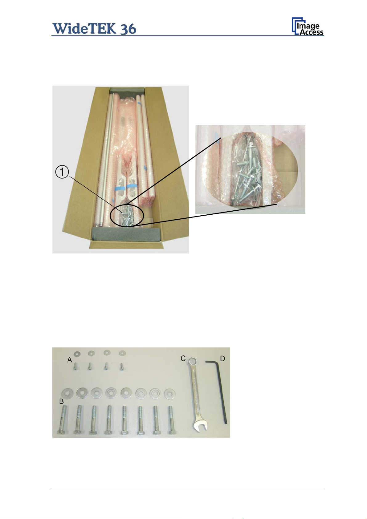
A.1.1 Contents of Floor Stand Box
The cardboard box of the floor stand contains all screws and washers, as well as the tools
to assemble the floor stand, in a separate plastic bag.
Picture 2: Floor stand box opened
Picture 3: Assembling material
1: Plastic bag with assembly material
The plastic bag contains all screws, washers and tools to assemble the floor stand.
A.1.1.1 List of Assembling Material and Tools
A 4x screws DIN 912 M5x10
4x washer DIN 9021 – 5.3
C Combination wrench,
size 13
D Allen wrench size 4
B 8x screws ISO 4016 – M8x50x22-WS
8x washer DIN 9021 – 8.4
Setup and Assembly Manual Page 15
Page 16

A.1.2 Floor Stand Overview
The engineering drawing below shows all major elements of the floor stand.
Picture 4: Technical drawing of floor stand
The floor stand is built out of five different components and one round rod.
No Qty Description
1 2 Horizontal traverse. This part is used on the top as well as on the bottom.
2 2 Vertical leg. This part is used on the left as well as on the right side.
3 2 Foot bracket. This preassembled part is used on the left and right side.
4 4 Adjustable feet. These are preassembled to the foot bracket.
5 2 Top bracket: This part is used on the left and right top side.
6 1 Horizontal rod. This part supports the paper exit basket.
Page 16 Setup and Assembly Manual
Page 17

A.1.3 Parts of Floor Stand
Take all parts out of the box and place them as shown below and check for possible
damages.
Picture 5: Floor stand components
The numbers in the picture above correspond to the numbers in the technical drawing.
Setup and Assembly Manual Page 17
Page 18

A.2 Assembling the Floor Stand
Start with the foot profile (component #3), the side pillar (component #2), and the traverse
(component #1).
Note: The three boreholes on the vertical leg (part #2) that are only on one side must
face to the inner side of the floor stand. They should also be in the upper part of
the leg. The technical drawing illustrates the correct position.
First insert a vertical leg into a foot bracket. The brackets have a cutout for the traverse.
The foot brackets are designed symmetrically, therefore either one fits left and right.
Picture 6: Side pillar in foot profile
Next, insert the traverse as shown in the picture below.
Picture 7: Traverse inserted into foot bracket
Page 18 Setup and Assembly Manual
Page 19

Fasten the three components with two screws ISO 4016 – M8x50x22-WS. Place a washer
on each screw.
Picture 8: Inserting screws with washer
Tighten the screws with the combination wrench, size 13, which comes with the floor
stand.
Note: All screws should only be hand-tightened at first. The components should have a
little play until all parts are assembled.
Repeat the steps described above with the second foot bracket and the second vertical
leg.
Upon completion, the floor stand should look as shown in the picture below.
Picture 9: Bottom and side components assembled
Setup and Assembly Manual Page 19
Page 20
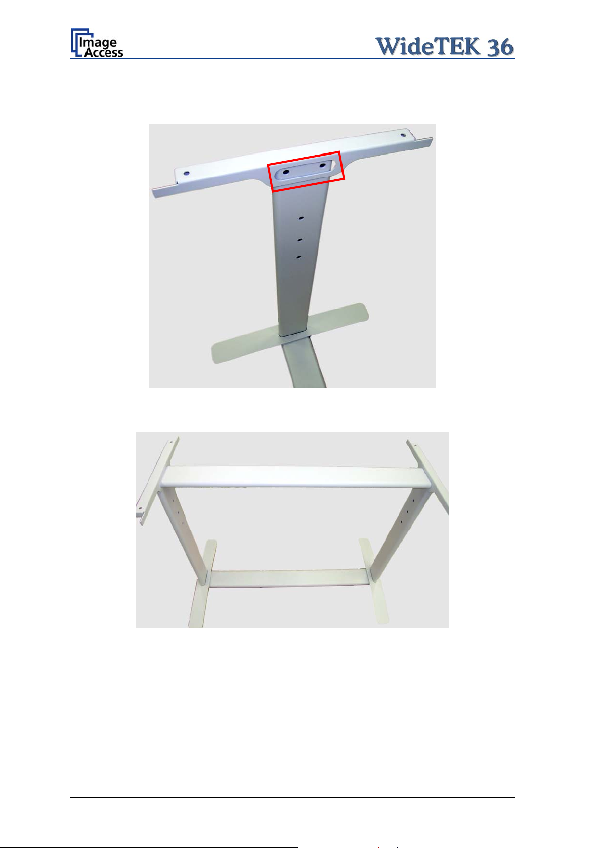
Place the top brackets on the vertical legs. The oval cut-out must face to the inner side.
Picture 10: Top bracket on vertical leg
Insert the second traverse between the side legs.
Picture 11: Upper traverse inserted
Assemble the traverse, the top brackets and the legs with two ISO 4016 – M8x50x22-WS
screws and a washer on each side.
Tighten all screws on the floor stand with the combination wrench, size 13.
Page 20 Setup and Assembly Manual
Page 21

Finally, insert the rod between the side legs. This rod supports the paper output tray. It
has three positions for varying tray positions.
Picture 12: Inserting the rod
A.3 Combining Floor Stand and Scanner
After assembling the floor stand, the WideTEK 36 scanner can easily be placed on it in a
safe position.
Note: For safety reasons, the scanner should be handled by two persons.
The transport box has notches at each corner in order to lift the scanner easily out of the
box.
Picture 13: Two persons lifting the scanner out of the transport box
Setup and Assembly Manual Page 21
Page 22

Place the scanner on the ground for the next steps.
To remove the foam rubber elements, lift the scanner on one of its small sides (Figure 1,
Picture 14) and turn the foam rubber element sideward (Figure 2, Picture 14).
Picture 14: Lift the scanner to remove the foam rubber element
Turn the foam rubber element up to an angle of approximately 45°, then pull it out of the
back side of the scanner.
Picture 15:Removing foam rubber element and cardboard element
Repeat this at the other side of the scanner. Finally remove the small cardboard elements
(Picture 15, detail 1) at the left and right side between scanner cover and side elements.
Page 22 Setup and Assembly Manual
Page 23

The WideTEK 36 scanner has four pre-mounted rubber feet on its bottom side. The
position of the rubber feet corresponds to the cut-outs at the top of the longitudinal girders.
Place the WideTEK 36 on the floor stand so that the rubber feet are inserted into the cutouts.
Picture 16: Bottom side, front side left Picture 17: Bottom side, back side left
Finally, fasten the WideTEK 36 onto the floor stand. The four screws DIN 912 M5x10 with
washers are used to fix the scanner.
Picture 18: Fastening the scanner onto the floor stand
The floor stand has boreholes on each side directly beside the cut-outs for the rubber feet.
Insert the screws and fasten them securely.
Use the Allen wrench to fasten the screws.
Setup and Assembly Manual Page 23
Page 24

After fastening the scanner on the floor stand, insert the paper exit basket. It is
recommended to insert the paper exit basket from the back of the scanner. Place it on the
rod and fix it with the hooks on the rear side of the WideTEK 36.
Picture 19: WideTEK 36 placed on floor stand, ready to use
Page 24 Setup and Assembly Manual
Page 25

A.4 Connecting to the Power Source
Before connecting the WideTEK 36 scanner to the wall outlet check the following items:
Ensure the wall outlet is in perfect condition and that it is properly
grounded.
Inspect the power cable and ensure that it is undamaged.
Use only the power cable delivered with the scanner.
Ensure that the wall outlet is equipped with a fuse with the proper
capacity.
Turn the device off before plugging or unplugging any cable.
The electrical outlet must be near this device and must be easily
accessible.
Setup and Assembly Manual Page 25
Page 26

A.4.1 Connectors at the Scanner
The connectors are positioned at the left side of the housing, seen from the operators
view (i.e. from the front of the scanner).
Picture 20: Connectors at WideTEK 36
1: Power connector
2: Foot pedal connector
3: Network cable connector
4: Main power switch
Page 26 Setup and Assembly Manual
Page 27

A.5 Powering up the WideTEK 36
The main power switch is found beside the power connector.
Picture 20 shows the position of power connector and main power switch.
After connecting the scanner to the electrical
position I. When the main power switch is in position I, the scanner is in stand-by mode.
Note:
While using the WideTEK 36 in work conditions, it should
only be switched on and off by the touch panel!
outlet, switch the main power switch to
A.6 WideTEK 36 Touch Panel
The WideTEK 36 parameters can be set and modified with the integrated touch panel. It
shows an easy-to-use menu and helps the user to control all scanner parameters with the
touch of a finger.
When the WideTEK 36 is powered up by using the main power switch, the touch panel is
illuminated in a dimmed mode and shows the stand-by screen. The stand-by screen
shows the Image Access logo and the blinking message Touch screen to power up.
A.6.1 Starting the WideTEK 36 from Stand-By Mode
When the WideTEK 36 is in stand-by mode, it can be started by tapping the touch panel
on any arbitrary position. The touch panel lights up and a rotating hourglass indicates that
the start sequence is running.
When the start-up sequence is finished, the touch panel shows the start menu screen.
Picture 21: Start menu screen
Setup and Assembly Manual Page 27
Page 28

A.6.2 Turning-off the WideTEK 36
Note:
To turn the WideTEK 36 off, press and hold the Stop button on the touch panel.
While the Stop button is held, a counter in the button shows the remaining time until the
WideTEK 36 is powered down. “Going to sleep in x seconds”
Always turn off the WideTEK 36 scanner with the Stop button on the
touch panel!
The main power switch should only be used when the WideTEK 36 is
in stand-by mode and before the scanner is disconnected from the
electrical outlet.
Picture 22: Touch panel while shut down in progress
At the end of the power-down sequence the display will be dimmed.
A.6.3 The Help Function
To support the user when working with the WideTEK 36, a help function is integrated into
the touch panel menus. A Question Mark (?) symbol in the lower right corner of the
screen activates the help function.
After touching the question mark, all controls in the screen start blinking. To get the
corresponding help text, the appropriate control must be touched. To return to the
respective screen, the screen must be touched again on any arbitrary place.
Page 28 Setup and Assembly Manual
Page 29

A.7 Navigating through the Screens
Some of the screens show on the bottom line the buttons
Returns to the former screen. Sometimes only the symbol < is displayed.
Switches to the next logical screen, e.g. from Format Control 1 to
Format Control 2. Sometimes only the symbol > is displayed.
Resets all values in the respective screen to default value.
A.7.1 How to Enter or Change Values
To enter new values or change existing values, the corresponding field or line in the
screen must be touched. If a parameter requires an alphanumeric value, the touch panel
display changes and shows a keyboard with which text and numeric values can be
entered.
Picture 23: Keyboard with capital letters
The keyboard enable
s the user to enter capital letters, lower case letters, special
characters as well as numbers.
The content of the keys is switched with this key:
Picture 24: Keyboard with lower case letters
Moves cursor to the left.
Moves cursor to the right.
Erases character.
Checkmark symbol returns to previous
screen.
Toggles between capital letters and
special symbols (e.g. backslash or @)
and lower case letters and numbers.
Setup and Assembly Manual Page 29
Page 30

A.8 IP Address Setup
Controlling of the WideTEK 36 scanner is based on the Scan2Net technology.
That means, access onto the scanner and the integrated Scan2Net user interface occurs
by using a network connection. For this connection, every browser software can be used.
IP address at delivery: 192.168.1.50
This IP address is also active after a “Reset to Factory Defaults”.
To integrate the scanner into an existing network structure all network parameters can be
defined and/or modified by using the touch panel as well as the integrated Scan2Net user
interface.
The following chapter describes how to setup the network parameters of the scanner by
using the touch panel. The setup of the network parameters in the Scan2Net user
interface is described in chapter B.3.1
A.8.1 IP Address Setup by Touch Panel
Start the WideTEK 36 from stand-by mode by tapping on the touch panel.
While the start sequence is running tapping on the touch panel at least three times
switches the scanner to setup mode. After the start sequence is finished, the touch panel
shows the Self Test 1 screen.
Picture 25: Self Test 1 menu
Page 30 Setup and Assembly Manual
Page 31

Touch the control field IP Address. The touch panel changes to a mask where
IP Address, Gateway, and Netmask can be entered. Also the DHCP mode can be
selected.
Picture 26: Network setup
Touch on the line to be changed, e.g. the Address line. The touch panel shows:
Picture 27: Numeric key pad
Enter the new values. The < and > keys move the cursor, the X key deletes the number at
the cursor position.
To finalize the input tap on the checkmark key.
If entries have been changed, a screen opens where the changes must be confirmed.
Yes confirms the changes, No discards the changes.
Picture 28: Confirm changes
After the changes have been saved, the touch panel shows the Self test 1 menu again.
Setup and Assembly Manual Page 31
Page 32

A.9 Optical Adjustment
Whenever the device is setup for the first time, moved to a different location, cleaned or
serviced and/or after a software update; some adjustments have to be performed to
guarantee maximum quality and accuracy.
A.9.1 White Balance
The white balance function is the most important function for consistent image quality.
To ensure optimal performance, the WideTEK 36 should be calibrated in regular intervals
to compensate for light degradation, variations in the paper quality of the documents to be
scanned, and other long term effects;
A.9.1.1 Helpful information about the white balance adjustment
The WideTEK 36 scanner has built-in light sources of known and stable quality consisting
of state-of-the-art white LEDs.
In the first step, the overall sensitivity of the scanner is adjusted in such a way that the
brightest area results in an almost saturated output signal. This assures that the largest
density range possible is used. After this adjustment is done, the uneven light distribution
on the CCD caused by the imbalance of the lamps, the ambient light introduced, the
imperfections of the lens and other factors has to be compensated for.
This measurement results in a correction function which levels the brightness over the
complete scan width.
The quality of the test target is of utmost importance to the result of the white balance.
The test target is on reflective paper which diffuses the light. If the test target has dirt,
wrinkles or anything visible to the human eye on it, the CCD will also see this and will
overcompensate in these areas. Although the internal software has been programmed to
eliminate these imperfections to a certain degree, it still leads to unreliable results if the
target is not of the defined quality.
If the target is of defined quality, the scanner will calibrate successfully. Calibration means
that the “white” of the test target in the given illumination situation produces a “white”
output in the digital domain. Consequently, all scans of white paper having different
properties than the test target results in brightness and possibly color shifts.
Periodically performing the white balance adjustment is recommended to ensure
consistent best scan results.
Page 32 Setup and Assembly Manual
Page 33

A.9.1.2 Performing the White Balance Adjustment
Start the scanner as described in chapter A.6.1. While the start sequence is running, tap
on the touch panel at least three times successively.
At the end of the start sequence the touch panel shows the menu Self Test 1 (Picture 25).
Tap on the field White Balance to activate the adjustment process.
< Back Returns to the former screen.
> Cont. Starts the measurement.
Abort Stops the measurement and the
display returns to the former
Picture 29: White Balance screen
Place the white balance test target WT36-Z-02-A in the document input. The test target
covers the complete width.
Now tap on > Cont.
screen.
While the white balance adjustment is
running, the touch panel shows a
progress indicator.
Picture 30: Progress indicator
At the end of the measurement the
result will be displayed in the touch
panel.
Tap on the field Finish to return to
the menu Self Test 1.
Picture 31: White balance result
Setup and Assembly Manual Page 33
Page 34

B Software Setup
Essentially, the scanner is a web server and comes with its own HTML-based user
interface. To access a Scan2Net scanner, any standard web browser can be utilized.
B.1 Start Screen of the Scan2Net User Interface
Start your browser.
Enter the IP address of the scanner. The default IP address of the scanner: 192.168.1.50
The start screen of the integrated user interface will be displayed.
Picture 32: Start screen
The start screen shows three symbols, which lead to the main categories of the Scan2Net
user interface.
Launch Scan Application changes to the main screen of the scanner interface.
Setup Device changes to the setup menu. Starting with the following chapter, the basics
of the scanner configuration will be described.
Information shows a list of basic information about the scanner, e.g. serial number, the
firmware version, the IP address and many more.
Page 34 Setup and Assembly Manual
Page 35

B.2 Setup Menu
Click in the start screen on the button Setup Device .
The next screen shows three buttons to select the login level. The access to the levels
Poweruser and Admin are password protected.
Picture 33: Login level screen
B.2.1 Selecting the Login Level
User This level allows the user to get some status information of the
WideTEK 36 scanner. This are e.g. the firmware version, the remaining
lamp operating time, system information, and many more. Furthermore it
allows to set a few basic parameters.
Poweruser Password protected level. Allows to set an extended range of system
parameters and to execute some adjustments.
Admin Password protected. Allows to set a wide range of system parameters and
to configure the scanner in detail.
Access to the Admin level is limited for trained technicians.
Setup and Assembly Manual Page 35
Page 36

B.3 Poweruser Login Level
For the following setup steps choose the login level Poweruser .
Default user name and default password for this login level are "Poweruser".
Note: Please consider that both the user name and the password are case-sensitive and
that the first letter of both the user name and password are upper case.
Picture 34: Poweruser main menu
The person having access to this level can change the password and thereby limit access
to normal operators.
The main menu screen for the Poweruser level opens. The main menu is separated in
several sections.
The subsequently described settings broaden the functionality of the scanner or activate
additional functions.
Page 36 Setup and Assembly Manual
Page 37

Note: For a detailed description of the User Settings see the Operation Manual,
chapter Setup Menu.
B.3.1 Setup Network IP Address
In the Poweruser main menu find the section Base Settings and click on the
Network Configuration button.
wt36_pwr-usr5xx_003.jpg
Picture 35: Network parameters of the scanner
Now change the IP address, subnet mask and gateway to a valid address in your network
or select DHCP to obtain an IP address automatically.
When the IP address has been changed, click on the Apply button. The new values will
be transferred and the scanner is accessible with its new IP address.
Note: Depending on the browser it is necessary to delete the browser cache before
the scanner is accessible.
Now enter the new IP address and open the login level Poweruser as described above
(chapter B.2 / B.3)
Setup and Assembly Manual Page 37
Page 38

B.3.2 Adjust Time & Date
In the Poweruser main menu screen (Picture 34) locate the section Base Settings. Click
on the button Adjust Time & Date .
Picture 36: Adjust Time and Date Screen
Select the time format.
Enter in section NTP Server all parameters for the communication with a NTP server.
Select the time zone and the daylight saving function.
Manually set the time and the date.
Click the button Manually to refresh all above modified data.
Click the button via NTP to connect to the above defined NTP server.
Note: By default, the name of a scanned image contains the scan time and date,
therefore synchronizing the internal clock can be of some value.
Page 38 Setup and Assembly Manual
Page 39

B.3.3 Sound Control
Locate the section Base Settings in the Poweruser main menu screen and click the
Sound System button.
Picture 37: Sound System screen
This menu allows to
set the volume,
upload additional sound files to the scanner,
link events to sound files.
Setup and Assembly Manual Page 39
Page 40

B.3.3.1 Set Volume
Click on the button Set Volume .
Picture 38: Volume level displayed
To set the volume level, click on the desired percentage value in the list left beside the
graphic symbol.
The symbol color changes depending on the selected value.
Up to 30% Up to 60% 70% or higher
Back to Sound Menu returns to the former menu.
Back to Main Menu returns to Poweruser main menu (Picture 34).
Page 40 Setup and Assembly Manual
Page 41

B.3.3.2 Wave Files
Additionally sound files can be uploaded to the already installed sound files. The data
format of the sound files is WAV.
Click on the button Wave Files .
Picture 39: List of sound files
The list of the installed sound files will be displayed.
Click on the button Search to search for the desired WAV sound files.
Click on the button Send to upload the files to the scanner.
Setup and Assembly Manual Page 41
Page 42

B.3.3.3 Link Events
A sound can be assigned to various action items. This will be played every time the
condition occurs. The default setting can be overwritten.
Click on the button Link Events
Picture 40: Link Sounds to Events screen
The list shows the event and the sound name which is linked to it.
The sound that should replace the current sound can be selected in the next row. Click on
the selection arrow to open the list of available sounds.
The selected sound will be linked to the event by clicking the symbol.
Click on the button Apply to transfer the changes to the scanner.
Back to Sound Menu returns to the former menu.
Back to Main Menu returns to Poweruser main menu (Picture 34).
Page 42 Setup and Assembly Manual
Page 43

B.3.4 Firmware Update
The Image Access Customer Service Portal at http://service.imageaccess.de offers
downloads of firmware updates for every Scan2Net scanner. As a registered user, login
with your personal login name and password.
Select Actions S2N Device Updates to download the current firmware version. Enter the
serial number of your scanner and the version number of the firmware installed on the
scanner.
Download the current firmware version to your local PC.
Start the scanner. Select Setup Device and go to the login level Poweruser .
In the main menu screen, locate the section Updates & Uploads and click the
Update Scanner Firmware button.
Browse your local PC and select the previously downloaded firmware update file.
Picture 41: Firmware Update
After the firmware update is complete the scanner must be rebooted to activate the new
firmware.
Select “Reboot” in the line Post update behavior to reboot automatically after the
updating the firmware.
Setup and Assembly Manual Page 43
Page 44

Click the button Send File to update the scanner’s firmware.
Important: Do not switch off the scanner while executing the firmware update!
The update sequence can last a few minutes. When the update is running, no messages
will be displayed on the screen.
After the firmware is successfully updated, the screen displays a summary.
Picture 42: Summary of successful firmware update
The scanner reboots now with factory default settings.
Page 44 Setup and Assembly Manual
Page 45

B.3.5 Install ICC Profiles
Find the section Updates and Uploads in the Poweruser main menu screen and go to
ICC Profile .
Select either Scanner Profile or Printer Profile .
Picture 43: ICC Profile screen
ICC profiles will be integrated in the image file data. ICC profiles adapt the color space
between scanner and image editing software or between scanner and printer.
By using an ICC profile a color-true reproduction of the scanned documents can be
provided.
Setup and Assembly Manual Page 45
Page 46

Browse for a new ICC profile and select it. If another ICC profile is already installed, it will
be displayed. Selecting another profile will replace the previous file.
Picture 44: Upload ICC Profile screen
Click on Browse to select the desired ICC profile.
Click on Send file to upload the selected profile. To activate the ICC profile click in the
Scan2Net user interface in the section Options on Embedded ICC Profiles.
Picture 45: Embed ICC profile
Page 46 Setup and Assembly Manual
Page 47

B.3.6 Install Option
In the main menu screen, locate the section Updates and Uploads and go to
Install Options . All option keys that are displayed in green are valid and installed. A new
key must be entered completely without blanks or spaces followed by the Apply button.
If it does not turn green, the key is invalid or does not belong to this specific scanner or
option.
Picture 46: Install Option screen
Note: Option keys are valid only for one option on a specific scanner denoted by its
serial number.
If a key is accidentally deleted it can always be obtained again at the Image
Access Customer Service portal http://service.imageaccess.de
at no extra
cost.
Setup and Assembly Manual Page 47
Page 48

B.3.7 White Balance
In the Poweruser main menu screen, locate the section Adjustments & Support.
Click the button Adjustments .
Picture 47: Click the marked button
In the next screen, locate the section White Balance Adjustments. In this section
click on the button White Balance .
Picture 48: Select „White Balance“
Page 48 Setup and Assembly Manual
Page 49

The next screen shows how to place the White Reference Target WT36-Z-02-A on the
document table.
wt36_setup_eng_020_b.jpg
Picture 49: White Reference Target on document table
Click on Next Step to start the White Balance Adjustment sequence.
After the White Balance Adjustment has finished, the results will be displayed in a status
screen.
Positive status will be displayed in green color.
Error message will be displayed in red color, followed by some explanatory remarks.
Setup and Assembly Manual Page 49
Page 50
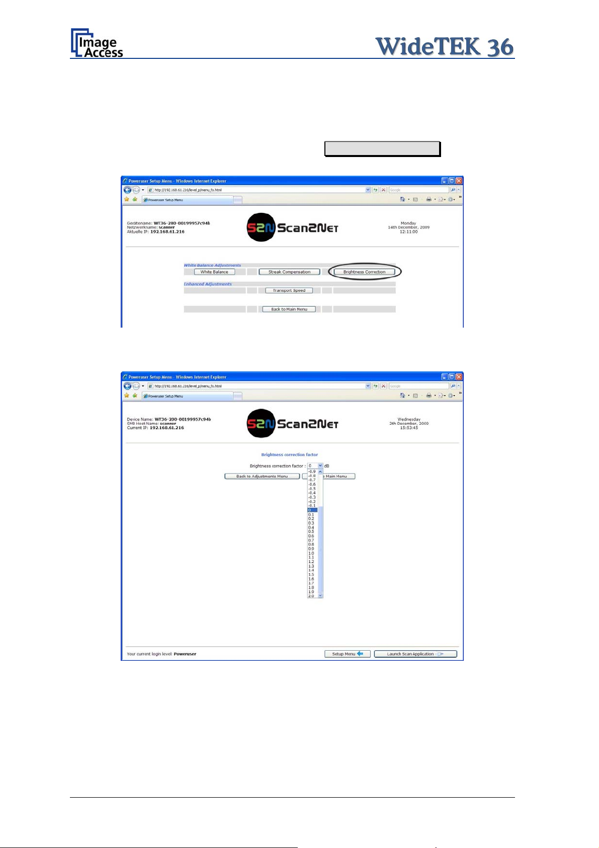
B.3.8 Brightness Correction
This function enables the user to change the gains settings up to +/- 2 dB, while positive
values make the scan look brighter.
To set the Brightness Correction, click the button Brightness Correction in the section
White Balance Adjustments.
Picture 50: Selecting “Brightness Correction”
This will open a screen in which the desired value can be selected from a list.
Picture 51: Selecting the correction factor
Page 50 Setup and Assembly Manual
Page 51

C Cleaning, Test and Troubleshooting
Although the WideTEK 36 scanner is constructed with the focus on a minimum of cleaning
requirement, it is needful to clean some parts after a period of using.
C.1 Cleaning the Transport Drums
When scanning documents the print color on the paper will soil the rubber material of the
transport drums. This can result in some cases in stripes on the paper of the scanned
document.
To avoid those stripes it is recommended to clean the transport drums in regular intervals.
Cleaning the drums is done very easily.
When the WideTEK 36 is in stand-by mode, start it by tapping the touch panel on any
arbitrary position. The touch panel lights up and a rotating hourglass indicates that the
start sequence is running.
While the start sequence is running the WideTEK 36 can be switched to Self Test mode.
Tapping on the touch panel at least three times switches to the setup mode. After the start
sequence is finished, the touch panel shows the Self Test 1 screen.
Picture 52: Self Test 1
The triangle arrows in the middle of the screen control the motor for the transport drum.
To clean the transport drums use a microfiber cleaning cloth and some drops of a
cleaning fluid, e.g. isopropyl alcohol.
Setup and Assembly Manual Page 51
Page 52

Open the upper unit by clicking the locking lashes at the left and right side of the housing.
Both transport drum are now visible.
Transport drums
Picture 53: Transport drums at front and back
Press and hold one of the triangle arrows on the display to start rotating the transport
drums.
Press the microfiber cloth at the transport drums.
Repeat this for each element of the transport drums.
Use a dry and fluff-free cloth to wipe off any remaining cleaning fluid from the transport
drums.
Page 52 Setup and Assembly Manual
Page 53

C.2 Cleaning the Glass Plate
To clean the glass plate open the upper unit by clicking the locking lashes at the left and
right side of the housing.
Use the microfiber cloth which is delivered with the scanner or a fluff-free cloth to clean
the glass plate.
Note: Because of the coating of the glass plate use only a few drops of a mild
cleaning fluid with the microfiber cloth.
C.3 Replacing the Glass Plate
If the glass plate is scratched it can be replaced as one part including the glass plate rack.
The following tools are needed:
Hexagon ball shaped head screwdriver, size 2,5 mm and 3 mm
Allen wrench, size 2,5 mm
At first the main cover has to be removed. The main cover has seven hexagon head
screws at the back side
Picture 54: Hexagon screws at WT 36 backside
and one hexagon screw on the left and the right side of the housing respectively.
Picture 55: Hexagon head screw at left side of housing
Setup and Assembly Manual Page 53
Page 54

After removing the screws the main cover can be lifted.
Note: Lifting of the main cover must be done carefully because of the cable which
connects the TFT display and the mainboard.
Picture 57 shows, how the main cover should be placed on the document table.
Picture 56: Lifting the main cover
Picture 57: Placing the main cover
In the next step disconnect the cables from the connectors at the TFT display.
Picture 58: Audio connector
Picture 59: Sensor connector
Page 54 Setup and Assembly Manual
Page 55

Picture 60: Controller connector
To open the last connector a hexagon ball shaped head screwdriver, size 2,5 mm, must
be used.
Notice the order of the elements on the screw: Lock washer Cable connector lock
washer.
This order must be the same when reconnecting the cables to the TFT display.
Picture 61: Cable connector
When all cables are disconnected, the main cover can be removed from the document
table.
Setup and Assembly Manual Page 55
Page 56

For the following step use an Allen wrench, size 2,5 mm.
The upper unit must be opened to reach the four screws which hold the glass plate rack.
It is recommended to begin with the two screws at the back. The next two pictures show
the position of the screws at the glass plate rack back.
Picture 62: Screw at back, left side
Picture 63: Screw at back, right side
At next remove the screws on the front side of the glass plate rack.
Picture 64: Screw at front, left side
Picture 65: Screw at front, right side
Page 56 Setup and Assembly Manual
Page 57

After removing the front screws, the glass plate rack hangs in the upper crossbeam. Hold
it at its external ends and lift it a little upwards.
Picture 66: Holding the glass plate rack
Then it can be removed in direction of the document table.
Picture 67: Removing the glass plate rack
The new glass plate rack will be mounted in reverse order. Ensure that all cables are
properly connected to the TFT display. Fasten the screw on the TFT display which holds
the cable connector only hand-screwed.
Setup and Assembly Manual Page 57
Page 58
C.4 Scan Test Targets
With the help of this function, the user can scan either a CSTT target or an IT8 target. The
targets are used to analyze specific features of the scanner’s camera and internal
parameters.
Some CSTT test target are delivered with the scanner.
In the Poweruser main menu screen find the section Adjustments & Support. Select
here Scan Test Targets . Another screen opens.
Select here either Scan CSTT Test Target or Scan IT8 Test Target .
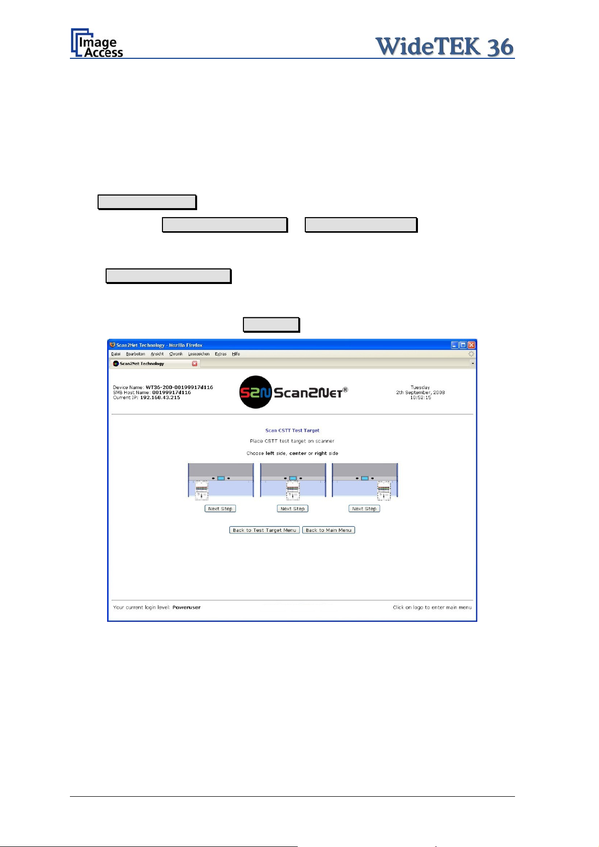
C.4.1 Scan CSTT Test Target
When Scan CSTT Test Target is selected, the next screen shows how to position the
target on the document table.
The CSTT test target can be placed at three position. Select a position corresponding to
the picture on the screen. Click on Next Step to start the test sequence
Picture 68: Position of CSTT target on the document table
The test target will be scanned and the image will be saved to a directory which is defined
by the user. The saved image can be used for support purposes.
Page 58 Setup and Assembly Manual
Page 59

C.4.2 Scan IT8 Test Target
When Scan IT8 Test Target is selected, the next screen shows how to position the
target on the document table.
Picture 69: Position of IT8 test target on the document table
The test target will be scanned and the image will be saved to a directory which is defined
by the user. The saved image can be used for support purposes.
Setup and Assembly Manual Page 59
Page 60

C.5 Network Analyzer
This function provides information about the data transfer speed of the network where the
Scan2Net scanner is installed.
Locate the section Adjustments & Support in the Poweruser main menu screen and
click the Network Analyzer button.
Picture 70: Network Analyzer screen
Click on the Perform Speed Test button and enter the IP address of the device which
should be the target for the test. Also enter the number of packets that should be sent for
testing. Click the Perform Test button to start the test.
Picture 71: IP address for testing
The test results will be
displayed in a diagram.
Page 60 Setup and Assembly Manual
Page 61

C.6 Recovery Function
The recovery function helps to set all device parameters to factory defaults after a fatal
system breakdown.
The recovery key is necessary to invoke the recovery procedure.
A recovery key is delivered with every device,
it is marked with the label Recovery.
Picture 72: Recovery Key
Important: The recovery function resets the IP address to the factory default value of
192.168.1.50. It may be necessary to use the crossover cable and change
the network settings on the local computer.
C.6.1 Important Notes Before Recovering to Factory Defaults
The steps described in the following should only be executed after a fatal system
breakdown!
Write down the values for the IP address, subnet mask and gateway of the device before
starting the recovery sequence.
After recovering to the factory default values, a firmware update has to be executed!
Make sure an update file is available on the local computer.
After recovering to the factory defaults, all adjustment procedures described in the
previous sections have to be executed again!
Setup and Assembly Manual Page 61
Page 62

C.6.2 How to Recover to Factory Defaults
1. Power the device down with the stop button.
2. Remove the metal compensator. This is down within a few steps easily.
At first open the upper unit by clicking the locking lashes at the left and right side of the
housing.
Then find a gap at the right side of the
compensators plate
Picture 73: Position of gap on right side
Picture 74: Position of gap on left side
Picture 75: Moving the compensator plate
upwards
and a gap at the left side of the
compensators plate where you can pull the
compensator plate upwards.
Pull the compensator plate slowly backwards
to the document table
Page 62 Setup and Assembly Manual
Page 63

Picture 76: Compensator plate on
document table
and place it on the document table.
In the next step, lift up two of the
compensators at the ri
ght side. Because of
the elastic rubber elements in the
compensator it could be necessary to fasten
them temporarily.
Picture 77: Compensators lifted
Picture 78: Inserting recovery key
Now the recovery key can be inserted.
Plug the recovery key into the serial port at
the connectors panel.
Picture 79: Connectors on rear panel
Setup and Assembly Manual Page 63
Page 64

3. Power the device up via the start button.
The device will start and, after it has found the recovery key to be present in the serial
port, it will automatically execute the recovery sequence. All viable system data will be
restored and necessary repair steps will be taken without the need of any user interaction.
Note: The recovery sequence can last some minutes. While the recovery sequence
is running, no message will be displayed.
4. When the recovery sequence has finished, the device will power down automatically.
Important: Do not switch off the device at any time during the recovery procedure!
5. Unplug the recovery key after the device has powered down.
6. Set the compensator into its basic position and insert the compensator plate.
7. Power up the device and launch the scan application in your browser.
The IP address of the device will have the factory default value: 192.168.1.50
8. Change the network parameters to the values which were used before running the
recovery sequence.
Select Setup Device Poweruser . Locate the section S2N Base Settings and
click the button Network . Enter the values for IP address, subnet mask, and default
gateway.
Click the Apply button. Confirm the following message by clicking the OK button.
In the next screen, click the Reboot button.
Reconnect to the device using the new IP address.
9. Select Setup Device Poweruser . Locate the section Updates & Uploads and
click the button Update Firmware . Perform a firmware update.
10. After the firmware update, all software adjustments for the device must be performed.
Select Setup Device Poweruser . Locate the section Adjustments & Support
and click the button Adjustments . Perform the adjustments by clicking the
appropriate buttons.
Page 64 Setup and Assembly Manual
Page 65

C.7 Error Codes
The scanner does report error conditions on the display and through the API. Some errors
are only sent to the API.
White background of the problem description indicates that the message is information
only.
A problem description with green background signals that operation of the scanner is still
possible although the error will have an influence on the behavior or quality of the
scanner.
Note: Problem description text with a red background indicates a critical error.
The device will be stopped and further scanning is inhibited.
Error # Error message shown in
the display
1 Scanner in use. An attempt to access the scanner was
2 Invalid session ID. An attempt to access the scanner with
4 Invalid password An attempt to access the scanner with
5 E05 S2N BOARD S2N board failure The S2N board is either not found or
6 E06 POWER SUPPLY
FAILED
7
USER BREAK Stop button pressed. The stop button was pressed during the
8 User timeout The function ended because of a time
9 Warming up The device is still warming up and
10 Invalid setting value. The value sent to the device is invalid.
11 Setting does not exist. The settings does not exist.
12 Invalid user docsize. The size of the user format is invalid.
14 Invalid resolution or color
15 Document feeding error. The document is not inserted correctly.
Document feeding error.
16 Paper over exit sensor Paper over exit sensor. Paper is found in the exit sensor region.
17 Paper in transport Paper in transport
18 Paper jam Paper jam
Error message sent to
Problem description
application
made from a different application.
an invalid session ID was made.
an invalid password was made.
found defective. Make sure board is
sitting correctly on the motherboard.
Power supply failed A problem with the internal power supply
was detected. Operation is not possible.
operation.
out
cannot be used.
Either the resolution or the color mode is
mode.
Please clear transport
Please clear transport.
invalid.
Please insert the document again.
Using “Transport speed” = “slow”
may help.
Pull paper out of the device.
Paper is found in the transport. Clean
transport first.
Paper jam occurred. Clear transport first.
Setup and Assembly Manual Page 65
Page 66

Error codes, part 2
Error # Error message shown in
the display
30 File format not supported. The specified file format is not supported
31 Preview not possible.
32
33
55 Error 55: Wrong S2N Board
(CCD Ports)
56 Error 56: S2N Board: wrong
revision
60 Error 60: General camera
error
61 Error 61: Loading camera 1
failed
62 Error 62: Loading camera 2
failed
63 Error 63: Loading camera 3
failed
65 Error 65: Camera 1 data bus
error
66 Error 66: Camera 2 data bus
error
67 Error 67: Camera 3 data bus
error
69 Error 69: ADC error camera 1 Camera 1 adc error. Test data transfer through analog digital
Error message sent to
Problem description
application
or it is invalid in combination with the
color mode.
The application specified an invalid
preview scale. Not all scale factors are
allowed with all image sizes.
The application specified an
invalid preview scale. Not all
scale factors are allowed with
all image sizes.
No image available
Wrong S2N board detected
(not enough CCD ports)
Wrong S2N Board detected
(Revision not OK)
General camera error.
Load camera 1 failed.
Load camera 2 failed.
Load camera 3 failed.
Camera 1 data bus error.
Camera 2 data bus error. Test data transfer to camera failed.
Camera 3 data bus error.
The application changed the color depth
between scanning and image transfer
and a conversion between these modes
is not possible. Example: scan in binary,
then changed color mode to truecolor.
The application attempted to get an
image from the scanner and there was
no scan since the device was turned on.
The S2N board found is not the right one
for this device. Error can occur after a
repair/exchange. Exchange with correct
board.
The S2N board found is not the right one
for this device. Error can occur after a
repair/exchange. Exchange with correct
board.
General error on the CCD camera board.
Check power, cables and S2N-PCI
board.
Initializing of camera 1 failed. Check
power, cables and S2N-PCI board.
Initializing of camera 2 failed. Check
power, cables and S2N-PCI board.
Initializing of camera 3 failed. Check
power, cables and S2N-PCI board.
Test data transfer to camera failed.
Check cables / connectors to camera 1
and S2N-PCI board.
Check cables / connectors to camera 2
and S2N-PCI board.
Test data transfer to camera failed.
Check cables / connectors to camera 3
and S2N-PCI board.
converter failed. Check cables /
connectors to camera 1.
Page 66 Setup and Assembly Manual
Page 67

Error codes, part 3
Error
Error message shown in
#
70 Error 70: ADC error camera 2 Camera 2 adc error. Test data transfer through analog digital
71 Error 71: ADC error camera 3 Camera 3 adc error. Test data transfer through analog digital
75 General keyboard error General keyboard error. Check keyboard
82 Bad scan background
Please clear transport
99 Internal error. The firmware has detected an internal
the display
Error message sent to
application
Bad Scan background
Problem description
converter failed. Check cables /
connectors to camera 2.
converter failed. Check cables /
connectors to camera 3.
and cables.
Automatic measurement can not be
executed. Remove documents from the
transport section.
error of unknown cause.
C.8 Warnings
Warning # Warning shown in the
display
83 Scan background was
changed
144 Light level is low
145 Camera adj ustment required Camera adjustment
160 W160 NO WHITE BALANCE
DATA
180 Deskew failed The deskew function failed. Reposition
181 Stitching2D: out of
182 Stitching2D: bad
Warning sent to
Problem description
application
Scan background was
changed
required
No white balance data No white balance data was found.
memory. Using fixed
stitching
matching. Using fixed
stitching
The background was changed. Repeat
scan sequence to correct the measured
value. Warning will disappear.
The light level is found to be low during
the white balance function.
General information about the camera
adjustment. Check for details and
readjust.
Perform white balance.
document.
There is not enough memory available
to complete the stitching function.
2D stitching can not deliver a matching
result. Switch to “Fixed” stitching.
C.9 Information
Infor-
mation
Information shown in the
display
#
200 CREATING
RECOVERY PART..
Setup and Assembly Manual Page 67
Information sent to
application
Creating Recovery
Partition
Description
While creating the recovery partition, the
scanner can not be accessed.
Page 68

D Technical Data
D.1 Scanner Specifications
Optical System
Maximum Document Width 38 inch / 965 mm
Scan Width: Max. 36 inch / 915 mm
Optical Resolution 1200 x 600 dpi
Sensor Type:
Sensor Resolution: 68.400 pixels (3x 22.800)
Scan Modes:
3 linear CCD, encapsulated and dust-proof
12bit grayscale (internal resolution)
36bit color (internal resolution)
1bit Black/White
8bit Grayscale
24bit Color, 8bit indexed
Illumination:
Light Source: Two lamps with 130 white LEDs each
Warm-up Time: None
Temperature Dependence: None
UV / IR Emission None
Lifetime 50.000 hours scanning time
D.2 Ambient Conditions
Operating Temperature +5 to +40° Celsius
Storage Temperature 0 to +60 °Celsius
Relative Humidity 20 to 80% (non-condensing)
Noise Level < 35 dB(A) (Operating)
< 25 dB(A) (Stand-by)
Page 68 Setup and Assembly Manual
Page 69

D.3 Electrical Specifications
This device is Energy Star compliant.
Voltage 100–240V AC
Frequency 50/60 Hz
Power Consumption
Stand-by 0.1 W
Start Procedure 190 W
Ready to scan, lamps off 115 W
Scanning 190 W
D.4 Dimensions and Weight
Scanner outer dimensions 220 x 1094 x 555 mm (H x W x D)
Scanner outer dimensions (incl. floor stand) 1070 x 1094 x 555 mm (H x W x D)
Weight of Scanner 45,6 kg
Weight of Floor Stand / incl. Paper Output Tray 17,5 kg / 19,7 kg
Wood Transport Box:
Weight of Transport Box 26 kg
Dimension of Transport Box 540 x 1300 x 745 mm (H x W x D)
Total shipping weight 96 kg
Setup and Assembly Manual Page 69
 Loading...