

Page 1

Setup Manual
Page 2

File:
WT25-600_SetupManual_A.docx
Page 3

permission of
ther
t to change the described products, the specifications or
2012 by Image Access GmbH, Wuppertal, Germany.
Printed in Germany. All rights reserved.
Reproduction in who le or in part in an y form or medium without express written
Image Access is prohibited. Scan2Net® is a registered trademark of Image Access. O
designated brands herein are trademarks of Image Access.
All other trademarks are the property of their respective owners.
Image Access reserves the righ
documents at any tim e with out pr i or not ic e. For t he most recent version, al wa ys c hec k our web
site
www.imageaccess.de or the customer service portal at portal.imageaccess.de/
Setup Manual Page 3
Page 4

Introduction
Dear Customer,
We congratulate you on the acquisition of this innovative product from Image Access.
We at Image Access are proud of the work we do; it is the result of our extremely high
standards of production and stringent quality control.
With this scanner, Im ag e Ac ce ss of f er s a n ef f ici ent scanner which covers a wide scope of
applications due to its versatility. Its integrated web based user interface makes all
functions available in structured menus.
This manual is designed to lead the user through all necessary setup steps after the
WideTEK 25-600 has been delivered.
For this reason, we ask you to read this manual attentively before starting to work with the
scanner. By doing so, you will avoid errors from the beginning and you will be able to
control all functions from easily.
In addition please consider the following points:
• Damages to your unit may have occurred during shipping. Please check for
damages immediately after delivery of the unit. Inform your supplier if damage has
occurred.
• Read and ensure that you understand the safety notes. They were developed for
your protection and safety as well as to protect the unit.
• Regular maintenance conserves the high quality and safety of your WideTEK 25
scanner during the entire service life.
If you have any further questions, please feel free to contact your local dealer or
Image Access directly. Our staff will be happy to help you.
For your daily work with your new scanner, we wish you success and complete
satisfaction.
Regards
Your Image Access Team
Page 4 Setup Manual
Page 5

About this Manual
Setup Manual
The Setup and Assembly Manual is written for technical staff with some basic
mechanical as well as software skills. Many resellers will offer on-site installation;
therefore, large parts or all of the s etup manual might not be of interest to the reader. The
access level at which the setup and adjustment processes are performed is called “Power
user”. This “Power user” level is password protected from access by the normal operator.
All information about the normal operation and behavior of this device is found in the
Operation Manual.
All available manuals for this device can be downloaded from our customer service portal
at http://portal.imageaccess.de
manuals.
This manual is divided into the sections A to F.
Section A contains the safety notes and the safety precautions. These safety
precautions must be followed carefully to avoid injury to the user while
working with the scanner.
. Be sure to always check for the latest versions of these
Section B describes the scanner hardware and the first steps to take after the device
has been delivered.
Section C describes the setup and the adjustments which can be executed with the
touchscreen.
Section D describes the content and the functions of the Poweruser setup menu. A
wide variety of parameters of the scanner can be set and modified in this
level. It includes information about the firmware update procedure.
Section E contains information about troubleshooting and the lists of error codes and
warnings.
Section F shows all technical data and necessary declarations.
Setup Manual Page 5
Page 6

Version
Published in
Content/Changes/Supplements
A
September 2012
Preliminary version.
EMC information according to the standard EN 55022
device. Operation of these equipment in a residential area is likely to
cause harmful interference in which case the user will be required to correct the
Version History
Warning!
This is a class A
interference at his own expense.
Page 6 Setup Manual
Page 7

Table of Content
Introduction -------------------------------------------------------------------------- 4
About this Manual ----------------------------------------------------------------- 5
Version History --------------------------------------------------------------------- 6
A Safety Notes ------------------------------------------------------------------- 14
A.1 Safety Notes ...................................................................................................... 14
A.1.1 Marking of Safety Notes 14
A.2 Certification ........................................................................................................ 14
A.3 General Notice ................................................................................................... 14
A.4 Safety Precautions ............................................................................................. 15
B Hardware ----------------------------------------------------------------------- 16
B.1 Content on Delivery ............................................................................................ 16
B.1.1 Removing the Transport Box 18
B.2 Transportation Locks .......................................................................................... 19
B.2.1 Removing the transportatio n locks 19
B.2.2 Inserting the transportation locks 20
B.3 Device Location.................................................................................................. 21
B.5 Device Overview ................................................................................................ 22
B.5.1 Connectors on the Back 22
B.6 Connecting to the Power Source ........................................................................ 23
B.7 Connecting to the Network ................................................................................. 24
B.7.1 Connecting to the Power Source 24
B.8 Powering up the WideTEK 25-600 ..................................................................... 25
B.8.1 Starting the WideTEK 25-600 from Standby Mode 25
B.8.2 Switching the WideTEK 25-600 to Standby Mode 25
B.8.3 The Help Function 25
B.9 Maintenance ...................................................................................................... 26
B.9.1 Touchscreen 26
B.9.2 Surfaces 26
B.9.3 Glass plate 26
B.10 Repair ................................................................................................................ 26
Setup Manual Page 7
Page 8

Table of Content, part 2
C Setup and Adjustment ----------------------------------------------------- 27
C.1 White Balance ................................................................................................... 28
C.1.1 Helpful information about White Balance Adjustment 28
C.1.1.1 Executing the White Balance Adjustment 29
C.2 IP Address ......................................................................................................... 30
C.3 User Settings ..................................................................................................... 31
C.3.1 Change GUI 32
C.3.2 Configure GUI Selection 32
C.4 Time and Date ................................................................................................... 33
C.5 User Preset........................................................................................................ 34
C.5.1 Creating user defined presets 34
C.5.1.1 Activating a function in the menus 35
C.5.1.2 Saving the functions of the preset 36
C.5.1.3 Deleting a preset 36
D Poweruser Level ------------------------------------------------------------- 37
D.1 Setup Menu ....................................................................................................... 38
D.1.1 Selecting the Login Level 38
D.1.1.1 Navigating through the menus 39
D.2 Poweruser Login Level ...................................................................................... 40
D.3 Base Settings .................................................................................................... 41
D.3.1 User Settings 41
D.3.1.1 Display 42
D.3.1.2 Show Warnings 43
D.3.2 Network Configuration 44
D.3.2.1 IP Configuration Method 44
D.3.2.2 IPv4 (Network Interface 0) 45
D.3.2.3 IPv4 (Network Interface 1) 46
D.3.2.4 Domain Name Server 48
D.3.2.5 SMB Settings 49
D.3.2.6 Wireless LAN (Basic Settings) 50
D.3.2.7 Wireless LAN (LAN Interface) 51
D.3.2.8 Wireless LAN (Security) 52
D.3.2.9 Wireless LAN (DHCP) 53
Page 8 Setup Manual
Page 9

Table of Content, part 3
D.3.3 Adjust Time & Date 54
D.3.3.1 Time Format 55
D.3.3.2 Time Zone 56
D.3.3.3 Manual Adjustment 56
D.3.3.4 NTP Server 57
D.3.4 Sound System 58
D.3.4.1 Set Volume 58
D.3.4.2 Sound Files 59
D.3.4.3 Link Events 60
D.3.5 Install Options 61
D.4 Updates & Uploads ............................................................................................ 62
D.4.1 Update Scanner Firmware 62
D.4.2 ICC Profiles 64
D.4.2.1 Scanner Profile 64
D.4.2.2 Monitor Profiles 66
D.4.2.3 Printer Profiles 68
D.4.3 Touchscreen / Desktop 70
D.4.4 Java Apps 71
D.5 Adjustments & Support....................................................................................... 72
D.5.1 Adjustments 72
D.5.1.1 White Balance 73
D.5.1.2 Brightness Correction 75
D.5.2 Log Files 76
D.5.2.1 Show Log Files 76
D.5.2.2 Stitching Log enabled 77
D.5.3 Scan Test Targets 78
D.5.3.1 Scan CSTT Test Target 78
D.5.3.2 Scan UTT Test Target 80
D.5.3.3 Scan IT8 Test Target 80
D.5.4 Network Analyzer 81
D.5.4.1 Perform Speed Test 81
D.5.4.2 Network Packet Statistics 82
Setup Manual Page 9
Page 10

Table of Content, part 4
D.6 Administrative Settings ...................................................................................... 83
D.6.1 Wake up Remote Host 83
D.6.2 Change Password 84
D.6.3 Backup Settings 85
D.6.4 Restore Settings 86
D.6.5 Lock Web App 87
D.7 Resets & Default Values .................................................................................... 88
D.7.1 Set Scanner Defaults 88
D.7.2 Reset Factory Defaults 88
D.7.3 Reset Scanner Defaults 88
D.7.4 Reset Hardware Defaults 88
E Troubleshooting ------------------------------------------------------------- 89
E.1 Recovery Function ............................................................................................. 89
E.1.1 Important Notes Before Recovering to Factory Defaults 89
E.1.2 How to Recover to Factory Defaults 90
E.2 Troubleshooting ................................................................................................. 92
E.3 Error Codes and Warnings ................................................................................ 93
E.3.1 Error Codes 93
E.3.2 Warnings 95
E.3.3 Information 95
F Technical Data ---------------------------------------------------------------- 96
F.1 Scanner Specifications ...................................................................................... 96
F.2 Ambient Conditions ............................................................................................ 96
F.3 Electr ical Specificat ions ..................................................................................... 97
F.4 Dimensions and Weight ..................................................................................... 97
F.5 CE Decla ration of Conformity ............................................................................ 98
F.6 FCC Declaration of Conformity ........................................................................ 100
Page 10 Setup Manual
Page 11

Table of Pictures
Picture 1: Transport box ...................................................................................................16
Picture 2: Scanner covered cushion foils .........................................................................16
Picture 3: WideTEK 25-600in transport box, cover removed ............................................17
Picture 4: Transportation locks at bottom side .................................................................19
Picture 5: Minimum distances ..........................................................................................21
Picture 6: WideTEK 25-600 front view .............................................................................22
Picture 7: Connectors on the WideTEK 25-600 backside .................................................22
Picture 8: Touchscreen, Kiosk application ........................................................................27
Picture 9: Setup menu items ............................................................................................27
Picture 10: Setup menu, start screen ...............................................................................29
Picture 11: White Balance result ......................................................................................29
Picture 12: Content of IP Address menu ..........................................................................30
Picture 13: User Settings menu .......................................................................................31
Picture 14: Selectable presets .........................................................................................32
Picture 15: Presets selection screen ................................................................................32
Picture 16: Time and Date screen ....................................................................................33
Picture 17: User Preset screen ........................................................................................34
Picture 18: Start screen ...................................................................................................37
Picture 19: Login level screen ..........................................................................................38
Picture 20: Poweruser main menu ...................................................................................40
Picture 21: Display parameters ........................................................................................42
Picture 22: Show Warnings selector ................................................................................43
Picture 23: IP Configuration Method ................................................................................44
Picture 24: Settings of IPv4 (Network Interface 0) ............................................................45
Picture 25: Settings of IPv4 (Network Interface 1) ............................................................46
Picture 26: Domain Name Server parameters ..................................................................48
Picture 27: SMB Settings .................................................................................................49
Picture 28: Wireless LAN Basic Settings ..........................................................................50
Picture 29: Wireless LAN (LAN Interface) ........................................................................51
Picture 30: Wireless LAN (Security) .................................................................................52
Picture 31: Wireless LAN (DHCP) ....................................................................................53
Picture 32: Time Format ..................................................................................................55
Picture 33: Time Zone screen ..........................................................................................56
Picture 34: Manual Adjustment ........................................................................................56
Picture 35: NTP Server setting .........................................................................................57
Picture 36: Set Volume ....................................................................................................58
Picture 37: Sound Files list...............................................................................................59
Picture 38: Upload new sound files ..................................................................................59
Picture 39: Link Events list ...............................................................................................60
Picture 40: Options List ....................................................................................................61
Setup Manual Page 11
Page 12

Table of Pictures, part 2
Picture 41: Update Scanner Firmware ............................................................................. 62
Picture 42: Scanner Profile .............................................................................................. 64
Picture 43: ICC Profile installed ....................................................................................... 65
Picture 44: ICC Profile information .................................................................................. 65
Picture 45: Monitor Profiles ............................................................................................. 66
Picture 46: ICC Profile inf ormation .................................................................................. 67
Picture 47: Touchscreen menu, ICC profile selected ....................................................... 67
Picture 48: Printer Profiles ............................................................................................... 68
Picture 49: List of ICC profiles ......................................................................................... 68
Picture 50: Printer profile information ............................................................................... 69
Picture 51: Java Apps ..................................................................................................... 71
Picture 52: Adjustment start screen ................................................................................. 72
Picture 53: White Balance start screen ............................................................................ 73
Picture 54: White Balance results .................................................................................... 74
Picture 55: Brightness Correction .................................................................................... 75
Picture 56: Log files overview .......................................................................................... 76
Picture 57: Log file content .............................................................................................. 77
Picture 58: Available test target ....................................................................................... 78
Picture 59: Example for test target position ..................................................................... 78
Picture 60: Request after scanning the test target ........................................................... 79
Picture 61: UTT test target on glass plate ........................................................................ 80
Picture 62: IT8 test target on glass plate ......................................................................... 80
Picture 63: Network analyzer start screen ....................................................................... 81
Picture 64: Network Analyzing Parameters ...................................................................... 81
Picture 65: Measured Time ............................................................................................. 82
Picture 66: Packet Statistics values ................................................................................. 82
Picture 67: Wake up Remote Host .................................................................................. 83
Picture 68: Change password menu ................................................................................ 84
Picture 69: Small window at bottom line with inquiry for action ........................................ 85
Picture 70: Restore setting from ZIP file .......................................................................... 86
Picture 71: Message after r estorin g ................................................................................. 86
Picture 72: Enter password to lock the Scan2Net user interface ...................................... 87
Picture 73: Recovery Key ................................................................................................ 89
Picture 74: Connectors on the WideTEK 25 .................................................................... 90
Page 12 Setup Manual
Page 13

Setup Manual Page 13
Page 14

A Safety Notes
A.1 Safety Notes
Read and ensure that you understand the safety notes.
They are designed for your protection and for your safety.
Follow all safety notes to avoid damage to the device.
A.1.1 Marking of Safety Notes
All safety notes are marked with a warning sign.
A description of the potential hazard is found at the right side beside the warning sign.
WARNING!
<Text with description of potential hazard.>
A.2 Certification
The WideTEK 25-600 scanner fulfills all requirements of the following safety standards:
IEC 60950-1, International Safety Standard for Information Technology Equipment
UL 60950-1, Safety for Information Technology Equipment (US standard)
CAN/CSA C22.2 No.60950-1, Safety for Information Technology Equipment
(Standard for Canada)
EN 60950-1, Safety for Information Technology Equipment (European standard)
All approval marks can be found on the type label of the device.
A.3 General Notice
This manual describes the functions of a complete equipped WideTEK 25-600 scanner. If
your device is not equipped with all features, deviations are possible.
Page 14 Setup Manual
Page 15

this device to rain
A.4 Safety Precautions
Warning: Please read all the safety precautions before you operat e the scanner. Serious
injury can occur to you or to others if you do not know how to use it safely.
To prevent fire or shock hazard, do not expose
or any type of moisture.
Follow all safety precautions to avoid personal injury or damage to the device.
1. Place the scanner in a clean, well-ventilated room. Do not operate the scanner in an
area with poor ventilation.
2. Openings in the scanner’s housing in the front or at the back are provided for air
circulation. Do not cover or block the openings.
3. Do not place the scanner near a heat or cold emitting source such as a space heater,
furnace, or air conditioning unit.
4. Do not place the scanner near any devices or electrical boxes emitting high voltage.
5. Always place the scanner on a stable surface.
6. Do not lean on the scanner.
7. Do not place cups containing liquids or other such objects on the scanner. If liquid
spills into the scanner it can cause damage.
If this occurs, turn the scanner off, unplug the power cord fr om the wall receptacle and
contact the Image Access Technical Support (support@imageacccess.de).
8. Do not put any objects into any scanner housing openings unless specifically
instructed to do so by Image Access Technical Support.
9. Do not disassemble the scanner. If there is a need to disassemble the scanner, please
contact the Image Access Technical Support.
10. Do not use the scanner if it has been physically damaged. If this occurs, turn the
scanner off, unplug the power cord from the wall receptacle and contact the
Image Access Technical Support.
11. The scanner should be used only with the external power supply that is delivered with
the scanner. If you are unsure, please contact the Image Access Technical Support.
12. Always turn the power off and unplug the power cord from the wall receptacle before
cleaning the scanner.
13. When cleaning, only use Image Access approved cleaners. Do not use any type of
solutions, abrasives, or acids such as acetone, benzene, kerosene, mineral spirits,
ammonia, or nitric acid. Do not use any cleaners that contain these chemicals.
14. Use a dry or damp lint free cloth for cleaning the scanner.
15. Do not spray any liquids directly onto the scanner. Spray cleaning fluids only onto the
cleaning cloth and use the cloth to clean the scanner.
Setup Manual Page 15
Page 16

B Hardware
B.1 Content on Delivery
When delivered, the scanner is placed at a Euro pallet, bordered at all sides by a stable
wooden frame and covered with a wooden top cover.
Picture 1: Transport box
Remove the plastic straps and lift the cover. Remove the cushion foils, which cover the
scanner.
Picture 2: Scanner covered cushion foils
Page 16 Setup Manual
Page 17

Picture 3 gives an overview of the contents of the transport box.
Picture 3: WideTEK 25-600in transport box, cover removed
1: Folder with
Color Scanner Test Target CSTT-1
Manuals
2: Cardboard box with
Power supply and connecting cable
Network cable to connect the scanner to an existing network
Plastic bag with “Recovery Key”
3: Scanner WideTEK 25-600 in plastic protection bag
4: Plastic bag with
3x White Referenc e Target WT36C-Z-01-A
Stitching adjustment target WT36C-Z-02-A
Setup Manual Page 17
Page 18

B.1.1 Removing the Transport Box
Specially formed foam plastic inserts hold the scanner and the accessories in the
transport box.
At first, remove the plastic foam inserts and the cardboard boxes out of the transport box.
Start with the plastic foam elements at the corners of the scanner. Pull it out upwards.
Take the cardboard boxes out of the transport box at next.
Lift the wooden frame from the pallet.
Important! Because of safety reasons and because of the weight of the scanner,
execute the following step always with two persons.
Lift the scanner from pallet and place it on a flat and solid base.
The load bearing capacity of the base must correspond to the device weight. The
dimensions of the base must correspond to the length and depth of the scanner.
Note: Keep the wooden transport box and the foam plastic inserts for future use! In
case of guarantee the scanner must be sent back in the original transport box
to avoid transport damages.
Page 18 Setup Manual
Page 19

remove the transportation locks at both sides
B.2 Transportation Lock s
B.2.1 Removing the transportat ion locks
Attention
Before initial start-up
of the device!
The transportation locks are located at the left and right bottom side of the scanner. A
label is attached to each transportation locks.
Picture 4: Transportation locks at bottom side
The transportation locks are easily identified by their orange-colored heads.
To remove, turn the transportation lock counterclockwise.
Remove the transportation locks completely.
Important: Keep t he transport locks for future use!
The transportation locks must be inserted before each transport to protect the camera box
against damage.
Setup Manual Page 19
Page 20

B.2.2 Inserting the transportation locks
Attention
Insert the transportation locks before tr ansporting the scanner
to protect the camera box against damage.
Before inserting the transportation locks the camera box unit must be moved into transport
position.
The transport position of the camera box unit is at the back side of the scanner – seen
from the operator’s position.
When the power down sequence ends normally, the camera box unit moves to its
transport position. If the camera box unit is in any other position after switching off, restart
the scanner.
Turn it off again. The power down sequence moves the camera box unit t o the transport
position, finalizes all internal processes in the scanner and switches the device to
stand-by mode.
Finally switch off the WideTEK 25-600 at the main power switch (see Picture 7).
Insert the transportation locks at both sides of the scanner carefully.
Always use the transportation locks which come with the scanner.
Important: T ighten the transportation locks only by hand. Using more force could result
in damage of the camera box unit.
Page 20 Setup Manual
Page 21

B.3 Device Location
Please allow a minimum of 150 mm (6 inch) from any side walls and 300 mm (12 inch)
from a back wall. Leave one meter (3 feet) minimum distance from any door or entrance
way. Use t he illustration below as a guide.
Picture 5: Minimum distances
Do not operate the scanner in an area that has poor air circulation and/or that is nonventilated.
Place the WideTEK 25-600 on a flat and solid base. The load bearing capacity of the base
must correspond to the device weight.
Choose a location that complies with the limits of temperature and humidity. Refer to the
technical specification.
Important: Before using the WideTEK 25-600 scanner in the new environment allow at
least one hour for temperature adaptation.
Temperature adaptation means:
A fast change from cold to warm environmental conditions can build up
condensation inside the housing. This will result in unfavorable scanned
images and could cause permanent damages to the unit.
Setup Manual Page 21
Page 22
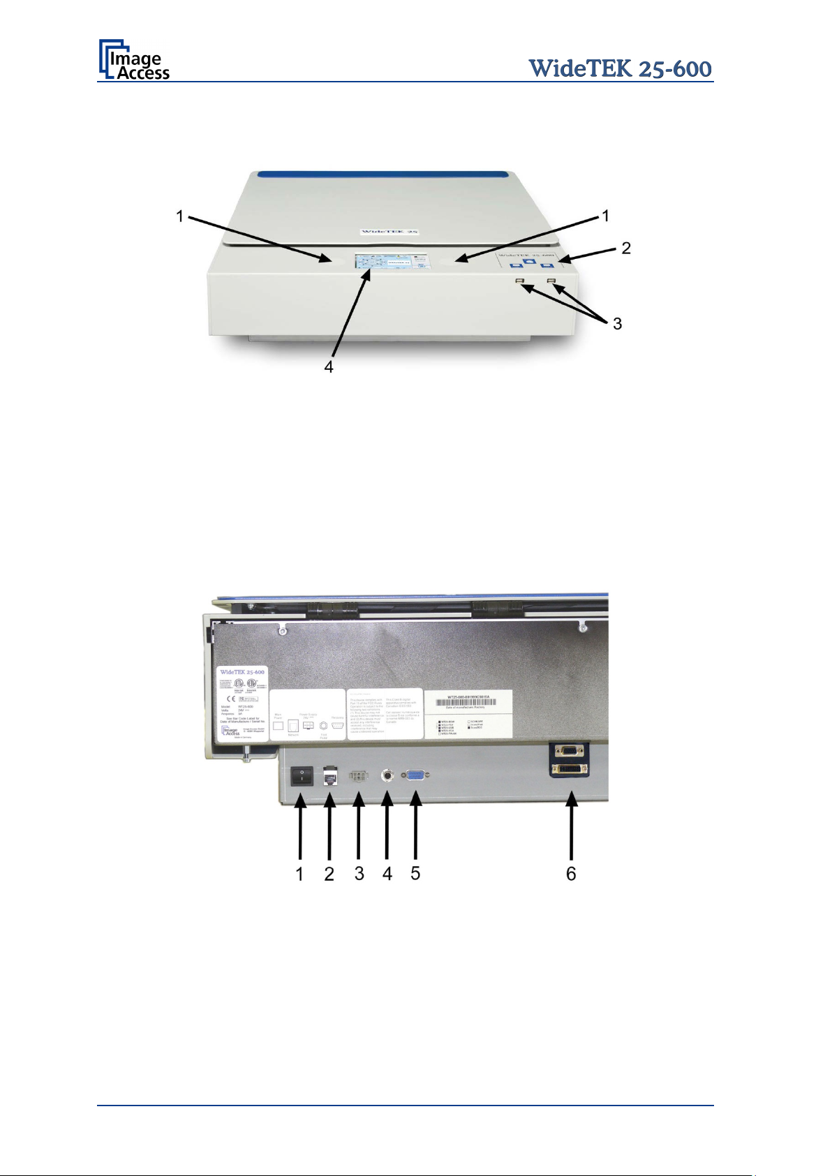
B.5 Device Overview
Picture 6: WideTEK 25-600 front view
The main components of the WideTEK 25-600 are:
1. Internal loudspeakers
2. On/off button and status LEDs of the USB connectors.
3. Two USB connectors for storage mediums.
4. Touchscreen
B.5.1 Connectors on the Back
Picture 7: Connectors on the WideTEK 25-600 backside
1. Main power switch
2. Network cable connector
3. External power supply connector
4. Foot pedal connector
5. Serial port / Recovery key connector
6. DVI / VGA connector
Page 22 Setup Manual
Page 23

Ensure the electrical outlet is in perfect condition and that it is
the electrical outlet is equipped with a fuse with the
The electrical outlet must be near this device and must be easily
B.6 Connecting to the Power Source
Before connecting the scanner to the external power supply and the power supply to the
electrical outlet, check the following items:
properly grounded.
Ensure that
proper capacity.
accessible.
Inspect the power cable and ensure that it is undamaged.
Use only the power cable delivered with the scanner.
Turn the device off before plugging or unplugging any cable.
The connector for the external power supply and the main power switch are located at the
right side of the back of the housing, seen from the operat or’s position (i.e. from the front
of the scanner).
After the power source is connected and the main power s witch is turned on, the symbol
in the on/off button lights up.
Red illumination of the on/off button signals that the WideTEK 25-600 is in standby mode.
Setup Manual Page 23
Page 24

Ensure the electrical outlet is in perfect condition and that it is
with a fuse with the
The electrical outlet must be near this device and must be easily
B.7 Connecting to the Network
Insert the network cable (delivered with the scanner) into the network cable connector
(Picture 7, #5). Connect the other side of the cable to a plug-in of an existing network.
Alternatively the scanner can be connected directly to a computer with network card by
using the crossover cable. In this case ensure that the network addresses used by the
computer and the scanner allow direct connection.
B.7.1 Connecting t o t he P ow e r S ource
Before connecting the scanner to the electrical outlet check the following items:
properly grounded.
Ensure that the electrical outlet is equipped
proper capacity.
accessible.
Inspect the power cable and ensure that it is undamaged.
Use only the power cable delivered with the scanner.
Turn the device off before plugging or unplugging any cable.
Page 24 Setup Manual
Page 25

Important:
Always turn off the WideTEK 25-600 scanner with the on/off
B.8 Powering up the WideTEK 25-600
The main power switch is found at the back of the scanner.
Picture 7 shows the position of power supply connector and main power switch.
After connecting the scanner to the external power supply, switch the main power switch
to position I. When the main power switch is in position I, the on/off button will be
illuminated and the scanner is in standby mode.
B.8.1 Star ti ng t he WideTEK 25 -600 from Standby Mode
Push the red illuminated on/off button to start the scanner.
The button illumination changes to blue.
The scanner starts with self-test routines and verifies all system components. Status
messages will be displayed on the touchscreen and on the TFT flat screen (if connected).
At the end of th e start-up sequence, the touchscreen displays the start screen.
B.8.2 Swit c hing the Wide TE K 2 5 -600 to S tandby Mode
button at the front panel!
The main power switch should only be used when the scanner is
in stand-by mode and before it is disconnected from the external
power supply.
To turn off the WideTEK 25-600 press and hold the on/off button for at least three
seconds. While pressing the button, a “click” sound is audible.
The content of the touchscreen and the TFT flat screen (if connected) changes and
display the message: Going to shut down now …
Finally the screens switch off and the on/off button will be illuminated red.
B.8.3 The Help Func t ion
To support the user when working with the WideTEK 25-600, a help function is integrated
into the touchscreen menu. A Question Mark (?) symbol in the bottom line of the
touchscreen activates the help function.
After touching the question mark, an additional window opens in the touchscreen and
shows information about the menu items of the selected menu.
Touching the OK button in the help screen closes the additional window.
Setup Manual Page 25
Page 26

B.9 Maintenance
Important: While cleaning the scanner, ensure that no liquids will penetrate into the
device housing.
B.9.1 Touchscreen
The touchscreen can be cleaned with a dry micro fiber cloth. Before cleaning it is
recommended to turn the scanner into standby mode.
B.9.2 Surfaces
Use a soft, dampened cloth to clean the housing of the scanner. Recommended is a micro
fiber cloth.
B.9.3 Glass plate
Important: Do not use any cleanser with solvents to clean the glass plate!
The glass pl ate of t he WideTEK 25-600 has a special non-reflective surface coating.
Clean the glass plate with an appropriate glass cleaner and use a soft cloth.
Recommended is a micro fiber cloth.
After cleaning dry the glass plate with a soft cloth.
B.10 Repair
Note: There are not any parts of the WideTEK 25-600 scanner which can be
repaired by the user.
All repairs should be done only by a trained technician.
Page 26 Setup Manual
Page 27

Touch here 10x
C Setup and Adjustment
Whenever the WideTEK 25-600 is setup for the first time, moved to a different location,
cleaned or serviced and/or after software update; some adjustments have to be performed
to guarantee maximum quality and accuracy.
Some adjustments can be executed directly via the touchscreen, e.g. the White Balance
calibration.
Furthermore, the IP address can be configured and other user settings can be defined.
To enter the setup menu, tap the touchscreen at the date and time section ten times
successively.
Picture 8: Touchscreen, Kiosk application
The screen will change and show the first screen of the setup menus.
The menu bar shows four of five available setup menus.
The small arrow in the menu Time and Date indicates t hat the menu bar can be scrolled
to show also the fifth menu items.
Picture 9: Setup menu items
The small arrow changes its position when the menu bar is scrolled.
Touching the Home button returns the touchscreen from the setup menu to
the user menu.
Setup Manual Page 27
Page 28

C.1 White Balance
The white balance function is the most important function for consistent image quality.
To ensure optimal performance, the WideTEK 25-600 should be calibrated in regular
intervals to compensate for light degradation, variations in the paper quality of the
documents to be scanned, and other long term effects.
C.1.1 Helpful information about White Balance Adjustment
The scanner has built-in light sources of known and stable quality consist ing of state-ofthe-art white LEDs.
In the first step, the overall sensitivity of the scanner is adjusted in such a way that the
brightest area results in an almost saturated output signal. This assures that the largest
density range possible is used. After this adjustment is done, the uneven light distribution
on the CCD caused by the imbalance of the lamps, the ambient light introduced, the
imperfections of the lens and other factors has to be compensated for.
This measurement results in a correction function which levels the brightness over the
complete scan width.
The quality of the test target is of utmost importance to the result of the white balance.
The test target is on reflective paper which diffuses the light. If the test target has dirt,
wrinkles or anything visible to the human eye on it, the CCD will also see this and will
overcompensate in these areas. Although the internal software has been programmed to
eliminate these imperfections to a certain degree, it still leads to unreliable results if the
target is not of the defined quality.
If the target is of defined quality, the scanner will calibrate successfully. Calibration means
that the “white” of the test target in the given illumination situation produces a “white”
output in the digital domain. Consequently, all scans of white paper having different
properties than the test target results in brightness and possibly color shifts.
Periodically performing the white balance adjustment is recommended to ensure
consistent best scan results.
Page 28 Setup Manual
Page 29
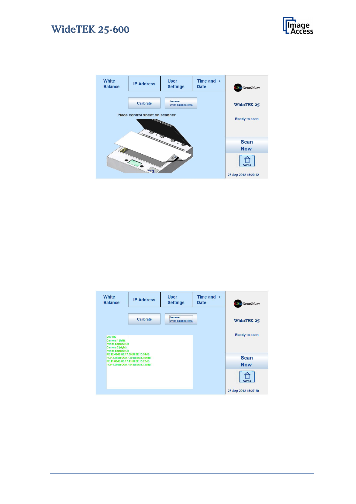
C.1.1.1 Executing the White Balance Adjustment
The first menu item of the setup menus is the White Balance screen.
Picture 10: Setup menu, start screen
The touchscreen shows how to position the reference target for the calibration.
The reference target is delivered with the scanner.
Place the white balance test target at the upper margin of the glass plate.
The test target covers the complete width of the glass plate and overlaps at the left and
right margin (see Picture 10) of the glass plate.
Touch the Calibrate button.
The calibration sequence will be executed. While the calibration is runni ng, a circulating
symbol is displayed. The calibration sequence takes approximately 40 seconds.
At the end of the calibration sequence, the results will be displayed on the touchscreen.
Picture 11: White Balance result
To erase the stored data, touch the button Remove white balance data.
Repeat the White Balance calibration after deleting the stored data.
Setup Manual Page 29
Page 30
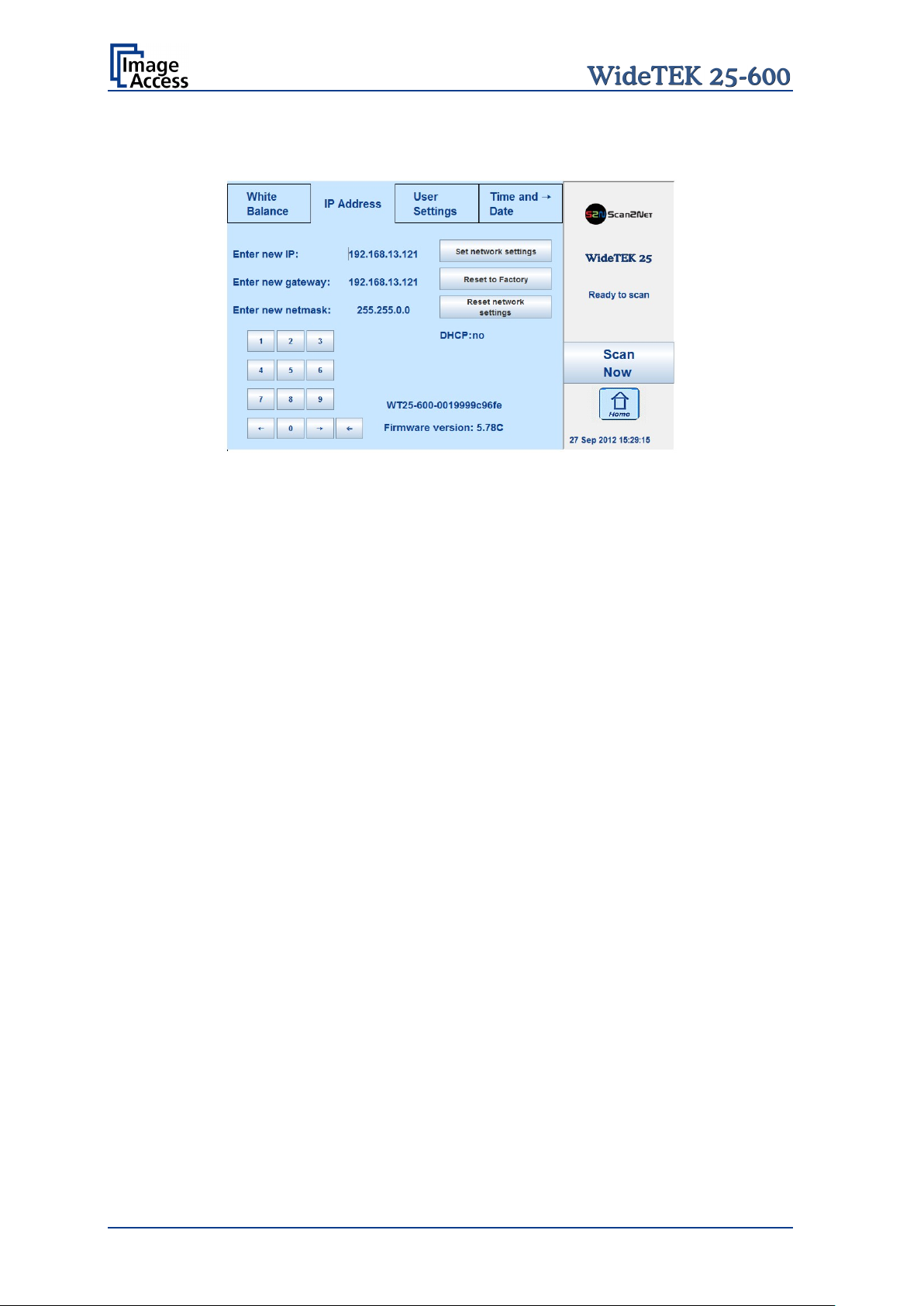
C.2 IP Address
Picture 12: Content of IP Address menu
To change or define the numeric values which make up an IP address , touch the number
in the respective line of IP address, gateway or netmask.
Touch the desired position in the respective row to move the cursor to that position.
To delete a digit, place the cursor right beside of the digit and press the “<=” button. It will
always be deleted from right to left.
Use the numeric keypad in order to enter digits.
Set network settings Saves the new or modified values when pressed.
Reset to Factory Sets all network parameters to factory default settings.
Reset network settings Sets all network parameters to previously defined value
when pressed. Chapter D.7.1 describes how to save the
parameters.
The section beside the numeric keypad shows device information.
Page 30 Setup Manual
Page 31

Language selector
setup menu remains primarily
C.3 User Settings
Picture 13: User Settings menu
The User Settings menu allows defining the touchscreen menu parameters.
Default Returns all scanner settings to default values.
Motor init Should only to be used by trained technicians for service
Change GUI Opens a menu window, which shows the predefined settings
Configure GUI Selection Opens a menu window that shows all available predefined
The currently selected language is displayed.
The touchscreen menu language can be selected by
touching the selection arrow. A list opens, showing the
available languages.
Touching the name of the desired language completes the
selection.
Note: The language of the
in English.
Changing the language will be activated after touching the
Home button.
purposes.
(presets) and allows selecting one of these. Chapter C.3.1
provides more details.
settings, with a checkbox before the name. Chapter C.3.2
describes more details.
Setup Manual Page 31
Page 32

C.3.1 Change GUI
Picture 14: Selectable presets
The Change GUI menu shows all predefined settings (presets). By default, the presets
Easy and Expert are defined.
Selecting App Selection switches the touchscreen to the s ystem start screen. Here the
user can select between the Scan2Net Kiosk application and App Selection screen.
The App Selection screen shows the presets and the apps which are available on the
scanner.
After selecting one of the presets, the scanner starts with the selected preset.
To return to the previous screen without selecting any preset, touch the Back button.
C.3.2 Configur e G UI S elect ion
Picture 15: Presets selection screen
All presets are displayed. The checkbox in front of each entry defines whether the
respective preset is displayed in the Change GUI screen.
After selecting the desired presets, touch the Back button to return to the previous screen.
Page 32 Setup Manual
Page 33

C.4 Time and Date
Picture 16: Time and Date screen
To change the time or date value, touch the value in the respective row.
Touch the desired position in the respective row to move the cursor to that position.
To delete a digit, place the cursor right beside of the digit and press the “<=” button. It will
always be deleted from right to left.
Use the numeric keypad in order to enter digits.
Store time and date: Saves the modified values when pressed.
Reset time and date: Sets the values to default values when pressed.
Setup Manual Page 33
Page 34

Create
Opens a screen with a keyboard. Enter the name for the new preset.
↑
Shifts the keyboard between upper case and lower case letters.
⇐
Deletes the character left from the cursor.
123 / abc
Shifts the keyboard between numeric and letter layout. All special char ac t ers
← or →
Positions the cursor while typing in the input field.
Apply
Saves the new preset.
Cancel
Returns to the former screen.
C.5 User Preset
Picture 17: User Preset screen
By default, two presets are defined.
Easy Contains only the basic elements of the kiosk application. This preset only
allows modifying a few parameters.
Expert Contains all elements of the kiosk application and allows control over all
scanner parameters.
C.5.1 Creat ing user defined presets
User defined presets can be created in a few steps.
remain at the same position.
Page 34 Setup Manual
Page 35

The touchscreen changes from the setup
Configure Touch this button to define the elements that will be displayed with the
preset in the kiosk application.
menu to the kiosk application.
The status section on the right side of the
kiosk application shows the message:
Configure GUI
C.5.1.1 Activating a function in the menus
Select a menu from the menu list on top of the touchscreen.
Touch one of the displayed buttons or controller near the respective title and hold for at
least three seconds. Release the button.
A small additional window opens, showing in three lines
• the title of the selected button or controller,
• the action called by the button,
• the buttons Ready and Cancel in the last line.
The first line always shows Disable <name of the selected function>.
Touch the selection arrow in the first line to change to Enable. This will show the available
functions in the second line.
Touch the selection arrow in the second line to show the available list of functions.
Setup Manual Page 35
Page 36

Selecting functions with the extension (a) will select automatically between button,
controller or list when the function is displayed at the touchscreen.
Functions with the extension (b) will always display a button at the touchscreen.
Touch Ready to save the selected function.
Touch Cancel to abort.
C.5.1.2 Saving the functions of the preset
After selecting the desired controller and buttons, return to the setup menu.
Touch the date and time section 10 times. The touchscreen will change directly to the
User preset screen (Picture 17).
Touch the Save button. This will save the preset with the defined name.
C.5.1.3 Deleting a preset
Select the preset to be deleted from the list.
Touch the Delete button. The preset will be deleted.
Page 36 Setup Manual
Page 37

D Poweruser Level
To enter the Poweruser level, start your browser and enter the IP address of the scanner.
Picture 18: Start screen
The start screen shows three symbols, which lead to the main categories of the Scan2Net
user interface.
Launch Scan Application changes to the main screen of the scanner interface.
Setup Device changes to the setup menu. Starting with the following chapter, the basics
of the scanner configuration will be described.
Information shows a list of basic inf ormation about the scanner, e.g. serial number, the
firmware version, the IP address and many more.
Select Setup Device to open the Setup menu.
Setup Manual Page 37
Page 38

D.1 Setup Menu
The Setup screen shows three buttons to select t he login level. The access to the levels
Poweruser and Admin are password protected.
The button Launch Scan Application starts the Scan2Net scan application.
The button Back returns to the former screen.
Picture 19: Login level screen
D.1.1 Selec ti ng t he Login Le vel
User This level allows the user to get some status information from the scanner.
These are e.g. the firmware version, the remaining lamp operating time,
system information, and many more. Furthermore it allows setting a few
basic parameters.
Poweruser Password protected level. This level allows setting an extended range of
system parameters and to execute some adjustments. It includes all
parameters of the User level.
Admin Password protected level. This level allows setting all system parameters
and to configure the scanner in detail.
Access to the Admin level is limited for trained technicians. It includes all
parameters of the User level and the Poweruser level.
Page 38 Setup Manual
Page 39

D.1.1.1 Navigating through the menus
The bottom line of each screen shows two buttons at the right side:
Setup Menu Returns to the login screen.
Launch Scan Application Switches to the main screen of the integrated Scan2Net
user interface
In each selection menu screen below the parameter to be set, the following button is
displayed:
Back to Main Menu Returns to the Poweruser main menu (Picture 20).
The log file section (Adjustments & Support Log Files) contains two more buttons:
Download Downloads the currently displayed log to a text file with
the extension “log”.
Back to Log File Menu Returns to the previous menu, where the desired log file
can be selected.
If data files can be selected and transferred within a menu, the menu contains the button
Send File Transfers the selected data file to the scanner, e.g. if a
firmware update is executed.
To install an option, a unique key code must be entered. The respective menu contains
the button
Apply Transfers the unique key code of the option to the
scanner.
Screens which show the result of measurements show the following buttons:
New Values Repeats the measurement and shows the result.
Setup Manual Page 39
Page 40

D.2 Poweruser Login Level
For the following setup steps choose the login level Poweruser .
Default user name and default password for this login level are "Poweruser".
Note: Please consider that both the user name as well as the password is written
with case-sensitive letters. The first letter of both the user name and the
password are written upper case.
Picture 20: Poweruser main menu
The person having access to this level can change t he password and thereby limit acces s
to normal operators.
The main menu screen for the Poweruser level opens. The main menu is separated in
several sections.
The subsequently described settings broaden the functionality of the scanner or activate
additional functions.
Page 40 Setup Manual
Page 41

D.3 Base Settings
The Base Settings section contains the basic parameters of the scanner.
D.3.1 User Sett ings
Please notice: The description of the User Settings can be found in the operation
manual, chapter The Setup Screen.
The number of parameters in the User Settings section is extended in the Poweruser
level by two parameters.
The parameters are Display and Show Warnings.
All other parameters are identical to the parameters displayed in the User Settings login
level.
Setup Manual Page 41
Page 42

To change the resolution, click the selection arrow in the line
To link an ICC profile to the monitor, click the selection arrow
The ICC profiles available will be displayed. Select the
D.3.1.1 Display
Use the function Display to define the resolution of the external monitor (optionally
installed) and to select an ICC profile.
Picture 21: Display parameters
If an external monitor is connected to the WideTEK 25-600 scanner, the matching
resolution for the monitor can be selected from a list.
Display Resolution.
Select the desired resolution from the list.
Restart the scanner to activate the setting.
in the line ICC Profile.
desired profile.
Restart the scanner to activate the setting.
Page 42 Setup Manual
Page 43

D.3.1.2 Show Warnings
Use the function Show Warnings to set warning messages on or off in the Scan2Net user
interface.
Picture 22: Show Warnings selector
If Yes is selected, warning messages will be displayed if an error occurs.
If No is selected, the warnings messages will be suppressed.
Setup Manual Page 43
Page 44

Manual
Allows setting the IP address, subnet mask, and default gateway manually;
DHCP
Sets the values for IP address, subnet mask, and default gateway
automatically, depending on the existing network where the scanner is
administrator of the local network before selecting the
D.3.2 Netw ork Conf iguration
The section Network Configuration is divided in nine subsections.
The Network Configuration start screen is t he IPv4 (Network Interface 0) screen, which
is described in chapter D.3.2.2. The following description starts with the IP Configuration
Method screen.
D.3.2.1 IP Configuration Method
The function IP Configuration Method allows the operator to select between two
methods of IP configuration of the scanner.
Picture 23: IP Configuration Method
corresponding to the network where the scanner will be used.
After modifying the above named values, the connection to the scanner
must be restored with the new data.
installed.
A DHCP server must be accessible in the network. For detailed inf ormation,
ask the network
DHCP method.
When selecting DHCP the connection to t he scanner is lost. T he connect ion
to the scanner must be restored with the new data.
Important for the next steps:
After changing the network settings, enter the new IP address of the scanner in your
browser and reopen the Poweruser main menu as previously described.
Page 44 Setup Manual
Page 45

IP address
Enter the IP address which should be used by the scanner.
Subnet Mask
Enter the value for the subnet mask.
Default Gateway
Enter the value for the gateway. In most cases this is the IP
D.3.2.2 IPv4 (Network Interface 0)
The function IPv4 (Network Interface 0) allows the operator modifying the param eter s f or
the “Network Interface 0”. This is the primary network and is used for communication with
external network devices.
Picture 24: Settings of IPv4 (Network Interface 0)
The screen shows the parameters for “Network Interface 0”.
address of the scanner.
After modifying the network parameters, click on the Apply button to transfer the new
settings to the scanner. The scanner is now accessible with its new IP address.
Note: After changing the IP address the connection to the scanner gets lost. Enter
the new IP address in your browser to get re-connected with the scanner.
Depending on the browser used, it is necessary to delete the browser’s cache
before the scanner is accessible.
Setup Manual Page 45
Page 46

IP address
Enter the IP address for the “Network Interface 1”.
Subnet Mask
Enter the value for the subnet mask.
Default Gateway
Enter the value for the gateway.
D.3.2.3 IPv4 (Network Interface 1)
The function IPv4 (Network Interface 1) allows the operator modifying the parameters for
the “Network Interface 1”. This is the secondary network and used for communication with
internal network devices, e.g. the WLAN module.
Picture 25: Settings of IPv4 (Network Interface 1)
The screen shows the parameters for the “Network Interface 1”.
The IP address 10.0.0.50 is pre-configured for the communication with the WLAN module.
Default IP address of the WLAN module: 10.0.0.1.
After modifying the network parameters, click on the Apply button to transfer the new
settings to the scanner. The “Network Interface 1” is now accessible with its new IP
address.
Note: Depending on the browser used, it is necessary to delete the browser cache
before the scanner is accessible.
Page 46 Setup Manual
Page 47

D.3.2.3.1 Solving a routing conflict in a network
As said before, the “Network Interface 0” is used for the communication with external
networks; “Network Interface 1” is used for the internal communication with the WLAN
module.
If the scanner should be operated in an existing network that is configured in the IP
address range 10.0.0.x/24 or 10.0.x.x/16 and a host with the IP address 10.0.0.1 is used
in this network, a routing conflict will occur.
In the following example the IP address of the WLAN module will be changed to the IP
address 172.16.0.1.
To solve the routing conflict, the following steps must be executed in the described order:
1. Note the network settings of the existing network, in which the scanner should be
integrated.
2. The “Network Interface 0” parameters of the scanner must be set temporarily to the
factory values. This can be done directly from the touchscreen (see chapter C.2).
IP address: 192.168.1.50
Subnet mask: 255.255.255.0
Default gateway: 192.168.1.50
3. Connect the scanner directly with a PC. The network parameters of the PC must
allow accessing a network with the address range 192.168.1.x.
4. Start the scanner and select the Poweruser setup level.
5. Select Base Settings Network Configuration Wireless LAN (DHCP). See
chapter D.3.2.9.
6. Set th e DHCP client range to 172.16.0.51 – 172.16.0.251. Click the Apply button.
7. Select Base Settings Network Configuration Wireless LAN (LAN Interface). See
chapter D.3.2.7. Set the parameters for the WLAN module as follows:
IP address: 172.16.0.1
Subnet mask: 255.255.255.0
Default gateway: 172.16.0.1
Click the Apply button. The connection to the WLAN module gets temporarily lost.
8. Select Base Settings Network Configuration IPv4 (Network Interface 1). See
chapter D.3.2.3. Set the parameters for “Network Interface 1” as follows:
IP address: 172.16.0.50
Subnet mask: 255.255.255.0
Default gateway: 172.16.0.50
Click the Apply button. The c onnection between WLAN module and scanner is now
accessible.
9. Select Base Settings Network Configuration IPv4 (Network Interface 0). See
chapter D.3.2.2. Enter the previously noted parameters according to t he network in
which the scanner should be used.
Setup Manual Page 47
Page 48

Domain Name
Enter the domain name here.
Primary DNS Server
Enter the address of the primary DNS server here.
Secondary DNS Server
Enter the address of the secondary DNS server here.
D.3.2.4 Domain Name Server
This section defines the parameters for the Domain Name Server.
Picture 26: Domain Name Server parameters
Page 48 Setup Manual
Page 49

SMB Hostname
Enter an SMB host name to identify the scanner in the
SMB Workgroup
Enter the SMB workgroup in which the scanner is
WINS Server
If a WINS server is used, enter the IP address of the
Use NTLMv2 Authentication
Select either Yes or No.
D.3.2.5 SMB Settings
This section defines the parameters for the SMB Settings.
Picture 27: SMB Settings
Note: The default settings are recommended.
network. Default is the MAC address of the scanner.
installed.
server or \\<Server name> here.
Setup Manual Page 49
Page 50

Band
Click on the selection arrow to open the list.
SSID
Enter a name to identify the WLAN of the scanner.
Channel Number
Auto: Recommended setting. Uses the channel with the best data
Broadcast SSID
The broadcast SSID is set automatically.
D.3.2.6 Wireless LAN (Basic Settings)
Use the function Wireless LAN (Basic Settings) to define the basic settings for the
WLAN module.
Note: T his menu is displayed only if a WLAN module is installed and if the settings for
IPv4 (Network Interface 1) and Wireless LAN (LAN Interface) fit together.
Picture 28: Wireless LAN Basic Settings
Note: The default settings are recommended.
Select from the list the desired band for the WLAN communication.
transfer performance.
To use a specific channel, click the selection arrow and select the
desired channel from the list.
After modifying the WLAN parameters, click on the Apply button to transfer the new
settings.
Follow the note regarding the reboot sequence.
Page 50 Setup Manual
Page 51

IP address
Enter the IP address of the WLAN module.
Subnet Mask
Enter the value for the subnet mask.
Default Gateway
Enter the value for the gateway.
D.3.2.7 Wireless LAN (LAN Interface)
Use the function Wireless LAN (LAN Interface) to def ine the network parameter for the
Wireless LAN module.
Note: This menu is displayed only if a WLAN module is installed and if the settings
for IPv4 (Network Interface 1) and Wireless LAN (LAN Interface) fit
together.
Picture 29: Wireless LAN (LAN Interface)
The screen shows the parameters for the WLAN module.
After modifying the network parameters, click on the Apply button to transfer the new
settings to the scanner. The scanner is now accessible with its new IP address.
Setup Manual Page 51
Page 52

Encryption
None: No encryption, no security.
Encryption according to the
Pre-Shared Key Format
Select between Passphrase and HEX (64 characters).
Pre-Shared Key
Enter a string as pre-shared key here.
D.3.2.8 Wireless LAN (Security)
Use the function Wireless LAN (Security) to define the parameters for wireless LAN
security.
Note: This menu is displayed only if a WLAN module is installed and if the settings
for IPv4 (Network Interface 1) and Wireless LAN (LAN Interface) fit
together.
Picture 30: Wireless LAN (Security)
The screen shows the parameters for wireless LAN security.
WPA 2: Recommended.
WPA 2 standard, high security.
After modifying the parameters, click on the Apply button to tr ansfer the settings to the
scanner.
Page 52 Setup Manual
Page 53

D.3.2.9 Wireless LAN (DHCP)
Use the function Wireless L AN (DHCP) to define the rang e of IP addresses that can be
used by the WLAN module for DHCP access.
Note: This menu is displayed only if a WLAN module is installed and if the settings
for IPv4 (Network Interface 1) and Wireless LAN (LAN Interface) fit
together.
Picture 31: Wireless LAN (DHCP)
Click in t he corresponding fields and enter the start IP address and t he end IP address to
define the address range that can be used.
Setup Manual Page 53
Page 54

D.3.3 Adjust Tim e & Date
The section Adjust Time & Date is divided into four subsections.
The Adjust Time & Date start screen is the Manual Adjustment screen. The following
description starts with the Time Format screen.
To set the time correctly for the scanner, execute the adjustments in the following order.
Select the time zone. See chapter D.3.3.2.
Set your local time with the manual adjustment. See chapter D.3.3.3.
Establish a connection to an NTP server. See chapter D.3.3.4.
Page 54 Setup Manual
Page 55

Time Format 12h
Time Format 24h
D.3.3.1 Time Format
The time shown in the headline of the Scan2Net user interface can be displayed in either
12h or 24h format.
Picture 32: Time Format
Click on the selection arrow and select the desired time format. The differences between
12h and 24h format are shown below.
Display from
00:00 to 11:59
Display from
12:00 to 23:59
Setup Manual Page 55
Page 56

D.3.3.2 Time Zone
Use the function Tim e Zone to define the time zone for the internal clock of the scanner.
Picture 33: Time Zone screen
Click on the selection arrow. A list opens.
Select the desired time zone f rom the list. The list will close and the selected setting is
effective immediately.
D.3.3.3 Manual Adjustment
Use the function Manual Adjustment to set time and date to be displayed in the headline
of the Scan2Net user interface.
Picture 34: Manual Adjustment
To set a value, click on the selection arrow beside the respective value.
Select from the list. The new value will be transferred directly to the system clock and is
displayed in the headline of the Scan2Net interface.
Page 56 Setup Manual
Page 57

D.3.3.4 NTP Server
Use the function NTP Server to def ine the address of time server.
Picture 35: NTP Server setting
To connect to a NTP server, the scanner must have a connection to the internet.
Ask your network administrator for special information concerning your local network.
Enter the address of the NTP server in the line NTP server. It is a necessary requirement
that your local network enables the scanner to connect with the internet.
Setup Manual Page 57
Page 58

Volume level
Up to 30%
40% to 60%
70% or higher
D.3.4 Sound System
The section Sound System is divided into three subsections.
The Sound System start screen is the Set Volume screen.
D.3.4.1 Set Volume
Use the function Set Volume to set the loudspeakers volume of the scanner.
Picture 36: Set Volume
A screen opens and shows a graphic to symbolize the volume.
Click on the percentage value to change the volume level. The color of the graphic will
change depending on the selected volume level.
Volume bar
color
To return to the previous screen click the button Back to Main Menu .
Page 58 Setup Manual
Page 59

D.3.4.2 Sound Files
Use the function Sound Files to list the sounds which are linked to system events.
Picture 37: Sound Files list
Scroll to the bottom of the list to search and upload new sounds to the scanner.
Picture 38: Upload new sound files
Click on the button Search to search the directories of your local PC and/or your
network for sound files.
Click on the button Send File to upload the selected file to the scanner. After uploading,
the file will be displayed in the list.
Click on the trash can icon to delete the file.
Setup Manual Page 59
Page 60

D.3.4.3 Link Events
Use the function Link Events to change the sounds linked to system events.
Picture 39: Link Events list
The list of links contains thirteen events.
The sound file that is listed at each event is dependent on the language set for the
scanner .
To identify the language of the sound file, an identifier can be added to t he file name. For
example “en” marks sound files in English language or “de” marks sound files in German
language.
Independent from the language selected for the scanner, every sound file can be linked to
every event.
Click on the selection arrow beside the sound file name. A list with all avail able sound files
opens.
Select the desired sound file from the list.
Click on the loudspeaker symbol to play the sound.
Page 60 Setup Manual
Page 61

D.3.5 Install Options
The section Install Options shows all available options for the scanner.
After clicking on Install Options a screen opens and lists all options which are available
for the scanner. Please be patient as it will take a moment to actualize the list.
Picture 40: Options List
To activate an option, a unique key must be entered. The key is valid only with one
specific scanner and cannot be transferred to another scanner.
The software keys can be purchased at the Image Access Customer Service Port al. Visit
the URL portal.imageaccess.de
and enter the data for your scanner to get the available
keys.
Enter the key in the respective line and click on Apply .
After activating the option, its color turns to “Green”, which indicates active options.
Setup Manual Page 61
Page 62

D.4 Updates & Uploads
In the section Updates & Uploads several updates can be initiated, screensavers can be
defined and installed and Java applications can also be installed. The PDF cover sheet
can be uploaded and activated here as well.
D.4.1 Update Sc a nne r Firmware
Upload a new firmware version to the scanner.
Picture 41: Update Scanner Firmware
The Image Access Customer Service Portal (CSP) at portal.imageaccess.de offers
firmware updates for every Scan2Net scanner. In order to download the appropriate
firmware version update for your scanner, you must be a registered user. Log in to t he
CSP with your personal login name and password.
Select Actions S2N Device Updates to download the current firmware version.
Follow the steps described on the website. Download the ZIP archive of the current
firmware version to your local PC.
The ZIP archive contents:
• Three “txt” files with information concerning the installation, t he release notes and
the version number.
• One “tar” archive with the firmware
Important: Never unpack the “tar” archive file!
Always send the complete ZIP archive to the scanner!
Page 62 Setup Manual
Page 63

In the screen Update Scanner Firmware (see Picture 41) click on the selection arrow
beside “Post update behavior” of the scanner from the list.
Select Reboot from the list. This will start the scanner automatically after the firmware
update sequence is completed.
Browse your local PC and select the previously downloaded firmware update file.
Click the button Send File to transfer the selected firmware file to the scanner.
Important: Do not switch off the scanner while executing the firmware update!
Transferring the firmware file can take a couple of minutes, depending on the network
performance. While the update is running, no messages will be displayed on the screen.
After the firmware is successfully updated, the screen displays a summary.
To finalize the update process, the scanner must be rebooted. This is done automatically
if Post Update Behavior is set to Reboot.
If Shutdown is selected, the scanner powers down at the end of the firmware update.
When restarting after a firmware update, the scanner reboots with factory default settings.
Note: A White Balance adjustment must always be executed after a firmware update.
See chapter C.1 for more information about the White Balance adjustment.
All installed options will stay active.
Setup Manual Page 63
Page 64

Click the button to search the directories of your local PC and/or your
Click the button to load the selected file to the scanner.
D.4.2 ICC Pr ofi les
The section ICC Profiles is divided into the subsections Scanner Profile,
Monitor Profiles, and Printer Profiles.
ICC profiles are integrated in the image file data.
First of all, download the respective ICC profile for the device to your local PC.
D.4.2.1 Scanner Profile
The ICC profile loaded at Scanner Profile adapts the color space between scanner and
image editing software.
Select Scanner Profile to upload an ICC profile to the scanner.
Picture 42: Scanner Profile
Search
network for ICC profile files.
Send File
After uploading, the ICC profile will be displayed.
Activating the ICC profile:
Select Embedded ICC Profiles = Yes in section Options of the Scan2Net user interface.
Page 64 Setup Manual
Page 65

Picture 43: ICC Profile installed
To delete the ICC profile, click on the “Delete” symbol.
To get information about the ICC profile, click on the information symbol
Picture 44: ICC Profile information
Setup Manual Page 65
Page 66

Click on the “Delete” symbol to delete the ICC profile.
Click the button to search the directories of your local PC and/or your
Click the button to load the selected file to the scanner.
D.4.2.2 Monitor Profiles
The ICC profile will be adapted to the image data displayed at the external monitor of the
Bookeye 4 scanner.
Select Monitor Profiles to upload an ICC profile for the external monitor.
Picture 45: Monitor Profiles
Search
network for ICC profile files.
Send File
After uploading, the ICC profile will be displayed.
D.4.2.2.1 Selecting the ICC profile to be used
Select section User Settings, function Display (see chapter D.3.1.1) and select the ICC
profile as described.
Page 66 Setup Manual
Page 67

Click on the information symbol to get information about the ICC profile.
Picture 46: ICC Profile information
D.4.2.2.2 Activating the ICC profile To activate the ICC profile for the external monitor, select the menu Viewer & Job
Control in the touchscreen and mark the checkbox for the ICC Profile.
Picture 47: Touchscreen menu, ICC profile selected
Setup Manual Page 67
Page 68

Click the button to search the directories of your local PC and/or your
Click the button to load the selected file to the scanner.
To delete the ICC profile, click on the “Delete” symbol in the line of the
D.4.2.3 Printer Profiles
The ICC profiles for printers adapt the color space of the scanner to the color space of the
printer used with the scanner.
Select Printer Profiles to upload an ICC printer profile.
Picture 48: Printer Pro fi les
Search
network for ICC profile files.
Send File
After uploading, the ICC profiles will be displayed.
Picture 49: List of ICC profiles
ICC profile to be deleted.
Page 68 Setup Manual
Page 69

T o get information about the ICC profile, click on the information symbol in
the line of the ICC profile.
Picture 50: Printer profile information
D.4.2.3.1 Selecting the ICC profile to be used
In the S2N user interface of the scanner click on the link Options below the button Copy.
The Printer Preset window opens. Click on Printing Enhancements .
Select Color Matching ICC Profile.
The additional line ICC Profile is added to the menu below Color Matching.
Click on the selection arrow. All installed ICC profiles will be listed.
Select the desired ICC profile from the list.
Setup Manual Page 69
Page 70

D.4.3 Touchscr ee n / De s k t op
These functions are temporarily not available.
Page 70 Setup Manual
Page 71

To delete a Java App from the list, click o n the “Delete” symbol at
To get information about the Java App, click on the information
Upload new
D.4.4 Java Apps
This section enables installing and selecting Java applications for special user-defined
tasks.
Picture 51: Java Apps
The installed Java Apps are listed on the screen.
the right side of the line.
symbol in the line of the Java App.
Click on the Search button to search t he directories of your local
Java App
PC and/or your network for a Java Application file.
Click on Send File to transfer the selected file to the scanner.
Setup Manual Page 71
Page 72

D.5 Adjustments & Support
D.5.1 Adjustments
The Adjustment screen shows the links to the optical adjustments.
Picture 52: Adjustment start screen
The optical adjustment of the WideTEK 25-600 contains one menu item:
The section White Balance Adjustments contains two buttons.
White Balance Executes the white balance measurement
Brightness Correction Sets the level for the brightness correction.
Page 72 Setup Manual
Page 73

D.5.1.1 White Balance
The white balance function is the most important function for consistent image quality.
To ensure optimal performance, the WideTEK 25-600 should be calibrated in regular
intervals to compensate light degradation, variations in the paper quality of the documents
to be scanned, and other long term effects. For more information about the white balance
adjustment see chapter C.1.1.
Click on the button White Balance .
Picture 53: White Balance start screen
Place the test target (delivered with the scanner) as shown on the glass plate of the
scanner. Because if its dimensions, the test target overlaps at the left margin and at the
right margin of the glass plate.
Click on the Next Step button to start the measurement. The measurement can take up
to 40 seconds. While the measurement is executed, the screen shows a running symbol.
Setup Manual Page 73
Page 74

After completing the measurement, the screen shows the results.
Picture 54: White Balance results
Note: It is normal that the measurement will return different values each time the
measurement is repeated. The lens motor has a very high resolution and the
best focal point has to be found in the already large focal range, therefore a
variation of 50 – 100 in values is normal.
Page 74 Setup Manual
Page 75

D.5.1.2 Brightness Correction
The brightness correction function does not perform any measurements; it only allows
setting a correction factor for the brightness. The interval of the correction factor is ± 2 dB.
Picture 55: Brightness Correction
Click on the selection arrow.
The list of the available values will be displayed.
Click at the desired correction factor. The correction factor will be effective immediately.
Setup Manual Page 75
Page 76

Log file
Content
SMTP Log
SMTP transfers will be logged with all transfer data.
Update Log
All firmware updates will be logged.
SMB Log
SMB transfers will be logged with all data.
Copy Log
The data transfer between scanner and printer will be logged.
USB Log
The data transfer to connected USB devices will be logged.
Web Log
The data transfer to a target in the internet will be logged.
Scanner Log
All system activities of the scanner will be logged.
Billing Log
All billing relevant data will be logged.
D.5.2 Log File s
D.5.2.1 Show L og Files
While working with the scanner, the activities will be logged in several log files.
Picture 56: Log files overview
FTP Log FTP transfers will be logged with all transfer data.
All logs can be saved as ASCII files.
Page 76 Setup Manual
Page 77

Click on the button for the desired log file to view its contents.
Picture 57: Log file content
Depending at the selected log file, the amount of information varies.
Click on the Download button to save the content of the log file.
A dialog box opens where the operator can select between saving and opening the log
file. If the operator selects saving, the file will be saved in ASCII format, which can be
opened with any text editor program.
The “Scanner log” file has the most comprehensive content and gives a good overview of
the scanner activities.
D.5.2.2 Stitching Log enabled
This log file is only available with the flat bed and large format scanners.
The log file is a ZIP archive and contains information to analyze the stitching algorithm . It
is password protected and cannot be opened by the user.
In case of an error the ZIP archive should be sent to the Image Access support. It will help
to analyze the error and to find a solution.
Setup Manual Page 77
Page 78

D.5.3 Scan Test Targets
For system analysis and troubleshooting, three test targets can be used.
The CSTT test target and the IT8 test target included with the scanner.
D.5.3.1 Scan CSTT Test Target
Click on the respective butt on to select the CSTT test target for the scan sequence.
Picture 58: Available test target
The next screen shows the position of the CSTT test ta rget at the glass plate.
Picture 59: Example for test target position
Note: The printed side of the test target must be placed on the glass plate!
Page 78 Setup Manual
Page 79

Place two CSTT test targets on the glass plate as shown at the screen.
Click on the Next Step but ton to start scanning the test targ ets. The test sequence will
take approximately 30 seconds.
After scanning, the image will not be displayed.
A small window – depending on the browser used for scanning – opens.
Select between opening the image with an appropriate software application and saving
the im age.
The default image name contains the test target name, the device type and the serial
number of the scanner.
Picture 60 shows as example the window of the Mozilla Firefox browser.
Picture 60: Request after scanning the test target
The file name contains the following information:
CSTT-WT25-600-0019999c96fe
CSTT: Test target name.
WT25-600: Device type, here WT25-600
0019999c96fe: Serial number of the scanner.
This information is helpful for service technicians to f ind the scanner specific data in the
database.
The test target image contains information which allows analysis of the current settings of
the scanner and comparison with the factory settings.
Setup Manual Page 79
Page 80

D.5.3.2 Scan UTT Test Target
Click on the respective button to select the UTT test target for the scan sequence.
Note: The UTT test target is not included with the scanner.
Picture 61: UTT test target on glass plate
The procedure is the same as described with the CSTT test target.
The resulting image differs in the name because of the other test target.
D.5.3.3 Scan IT8 Test Target
Click on the respective button to select the IT8 test target for the scan sequence.
Picture 62: IT8 test target on glass plate
The procedure is the same as described with the CSTT test target.
The resulting image differs in the name because of the other test target.
Page 80 Setup Manual
Page 81

Target Address
Enter an IP address which can be accessed from the scanner to test
Packet Count
Click on the selection arrow to set the number of transferred packets.
Starts the test sequence.
Returns to the network analyzer start screen.
Returns to the Poweruser level main menu (Picture 20).
D.5.4 Network Analyzer
This menu allows to test the network performance and to view the packet statistics.
Picture 63: Network analyzer start screen
D.5.4.1 Perform Speed Test
Click on Perform Speed Test to check the date transfer speed.
Picture 64: Network Analyzing Parameters
the data transfer speed.
Perform Now
Back To Net Test Menu
Back To Test Suite
Setup Manual Page 81
Page 82

The result of the measurement is displayed at the next screen.
Picture 65: Measured Time
The bar graphic shows the three values:
Minimum The fastest transfer time between the scanner and the target address.
Average The average time for all transferred packets.
Maximum The maximum transfer time during the test.
Depending at the transfer time, the color of the bar changes.
D.5.4.2 Network Packet Stati st ics
Packet Statistics Shows the current network packet statistics.
Picture 66: Packet Statistics values
Page 82 Setup Manual
Page 83

D.6 Administrati ve Settin gs
D.6.1 Wake up Remot e Host
If an external PC is used with the scanner, it can be helpful to start the PC at the same
time when the scanner starts.
This can be automatized by activating the Wake up Remote Host function.
Picture 67: Wake up Remote Host
The requirements for using this function:
In the BIOS of the external PC the function “Wake on LAN” must be activated.
It may be necessary to update the BIOS of older PCs for this function to be available.
The main power of the external PC must be active, but the PC can be in “Power save”
mode.
Enter the MAC address of the network card of the PC in the line “Hardware address”.
Select “Yes” at the line “Wake up remote host at PowerOn”.
Setup Manual Page 83
Page 84

Select Level
Click on the selection arrow to open the list of log-in levels.
password should be
New Password
Enter the new password.
Retype New Password
Type the new password again.
D.6.2 Change Password
It is recommended to modify the password often, to protect the limited access to the
Poweruser level.
Click on Change Password .
Picture 68: Change password menu
Select the log-in level, for which the
changed.
Note: The system checks the syntax (upper and lower case) of the password.
Click on Clear Fields to clear the fields where the password can be entered.
Click on Apply to send the new password to the scanner.
The screen returns to the start screen of the Poweruser level.
Page 84 Setup Manual
Page 85

Open
Opens a window and shows the contents of t he ZIP file. T he ZIP f ile
Save
Saves the ZIP file with an automatically generated file name. The
Save as
Save the ZIP file. The desired file name can be entered before
Save and open
Saves the ZIP file and opens a window which shows the contents of
D.6.3 Backup Set t ings
To store the current settings of the scanner, a ZIP archive file can be created.
Click on Backup Setting to create the ZIP archive.
Depending on the browser used, a small window opens at the bot tom line of the current
window or a separate window opens. Picture 69 shows the small window at the bott om
when using the “Internet Explorer 9”.
Picture 69: Small window at bottom line with inquiry for action
contains a directory which is named according to the scanner device
type and its serial number. The directory can be opened but all files
therein are password protected and cannot be opened.
contents of the small window change after saving. The buttons in the
small window allow opening the ZIP file, the directory of the ZIP files
or opens the download lists in a separate window.
saving.
the ZIP file.
The ZIP archive contains printer specific settings, mail addresses for the data transfer via
SMTP or the network settings for SMB network share.
Using this function is recommended in order to have the current settings available after
the scanner has been reset to factory defaults (chapter D.7.2).
Setup Manual Page 85
Page 86

D.6.4 Restore S ett ings
With this function, the ZIP file stored with the “Backup Settings” function can be loaded to
the scanner.
Click on Restore Settings .
Picture 70: Restore setting from ZIP file
To find the ZIP archive, click on Search and browse the directory structure to find the
desired ZIP archive file.
Click on Send File to upload the file to the scanner.
After restoring the scanner settings, the screen shows a message and reminds the
operator to perform a White Balance sequence.
Picture 71: Message after restoring
Page 86 Setup Manual
Page 87

New Password
Enter the new password.
Retype New Password
Type the new password again.
D.6.5 Lock Web App
This function locks the Scan2Net user interface.
When the Scan2Net user interface is locked, the scanner can only be controlled by the
touchscreen or by external software.
Important: The user interface can only be unlocked from the Administrator level.
Picture 72: Enter password to lock the Scan2Net user interface
Note: The system checks the syntax (upper and lower case) of the password.
Click on Clear Fields to clear the fields where the password can be entered.
Click on Apply to send the new password to the scanner.
Setup Manual Page 87
Page 88

D.7 Resets & Default Values
D.7.1 Set Scanner Defaults
This function enables saving settings for color mode, resolution, document mode as well
as network parameters and other parameters. When powering up, the scanner starts with
the saved settings.
To modify the settings, switch to the Scan2Net user interface and set all param eters to t he
desired values.
Return to the Poweruser level.
Click on Set Scanner Defaults to execute.
All settings defined in the Scan2Net user interface will be active when the scanner starts.
The parameters defined for the output controls in the lower part of the S2N user interface
(see Operation Manual, chapter C “Software Operation”) will not be saved.
D.7.2 Reset Factory Defaults
This function sets all parameters back to factory settings.
The settings defined for printer output or the connections defined in SMB configuration or
the stored email addresses and other parameters will be erased and replaced by universal
entries.
Click on Reset Factory Defaults to execute the function.
D.7.3 Reset Scanner Default s
Resets all scanner parameters to the values which were set before with the
function Set Scanner Defaults .
Click on Reset Scanner Defaults to execute the function.
D.7.4 Reset Hardware Defaults
This function resets the hardware parameters t o the values which were defined during the
basic setup when assembling the scanner.
Page 88 Setup Manual
Page 89

E Troubleshooting
Disconnect the power cable before doing any maintenance to the
device.
E.1 Recovery Function
The recovery function helps to set all device parameters to factory defaults after a fatal
system breakdown.
The recovery key is necessary to invoke the recovery procedure.
A recovery key is delivered with every device;
it is marked with the label Recovery.
Picture 73: Recovery Key
Important: The recovery function resets the IP address to the factory default value of
192.168.1.50. It may be necessary to use the crossover cable and change
the network settings on the local computer.
E.1.1 Important Notes Before Recovering to Factory Defaults
The steps described in the following should only be executed after a fatal system
breakdown!
Write down the values for the IP address, subnet mask and gateway of the device
before starting the recovery sequence.
After recovering to the factory default values, a firmware update has to be executed!
Make sure an update file is available on the local computer.
After recovering to the factory defaults, all adjustment procedures described in the
previous sections have to be executed again!
Setup Manual Page 89
Page 90

1. Main power
E.1.2 How to Recover to Factory Defaults
Important: The scanner must be in stand-by mode before inserting the recovery key.
switch
2. Network cable
connector
3. External power
supply connector
4. Foot pedal
connector
5. Serial port /
Recovery key
connector
6. VGA and DVI
video output
Picture 74: Connectors on the WideTEK 25
connector
Plug the recovery key into the Recovery key connector (detail 5 in the above p icture) at
the connector panel.
Push the on/off button in the front panel to start the scanner.
The device will start and, after it has found the recovery key to be present in the port, it will
automatically execute the recovery sequence. All viable system data will be restor ed and
necessary repair steps will be taken without the need of any user interaction.
Note: The recovery sequence can last some minutes. While the recovery sequence
When the recovery sequence has finished, the device will power down automatically.
Important: Do not switch off the device at any time during the recovery procedure!
• Unplug the recovery key after the device has powered down.
• Power up the device and launch the scan application in your browser.
is running, no message will be displayed.
The IP address of the device has the factory default value: 192.168.1.50
Page 90 Setup Manual
Page 91

• Change the network parameters to the values which were used before running the
recovery sequence.
Select Setup Device Poweruser . Locate the section Base Settings and click
the button Network Configuration .
Enter the values for the IP address, the subnet mask, and the default gateway as
described in chapter D.3.2 Network Configuration and its sub-chapters.
Click the Apply button.
Reconnect to the scanner using the new IP address.
• Select Setup Device Poweruser .
Locate the section Updates & Uploads and click the
button Update Sscanner Firmware . Perform the firmware update.
• After the firmware update, the software adjustment for the device must be performed.
Select Setup Device Poweruser . Locate the section Adjustments & Support
and click the button Adjustments . Perf orm all adjustments in this section by clicking
the appropriate buttons.
Setup Manual Page 91
Page 92

E.2 Troubleshooting
Fields with a light blue background need t he power user access level. All other fields are
available to all users.
Problem Possible cause Action
Image is darker than
expected.
Image is brighter than
expected.
Image is darker on one side
than on the other side.
Image has horizontal stripes
or streaks.
Image shows a color shift
towards red (tint).
Image shows a color shift
towards blue (tint ).
The test target, which is
used for the white balance
procedure, is much
brighter than the
document.
The test target, which is
used for the white balance
procedure, is much darker
than the document.
The electronics gear is out
of sync.
Improper white balance.
The target used for white
balance is more blue than
the scanning target.
The target used for white
balance is more red than
the scanning target.
Go to the White Balance function.
Modify the Brightness Correction
setting.
Go to the White Balance function.
Modify the Brightness Correction
setting.
Exercise the Scan Start procedure.
Exercise the White Balance
procedure.
Go to the RGB adjustments and lower
the gain on red.
Go to the RGB adjustments and lower
the gain on blue.
Page 92 Setup Manual
Page 93

Error #
Error message shown in
Error message sent to
Problem description
application.
with an invalid session ID was made.
the operation.
sitting correctly on the motherboard.
the operation.
time out
cannot be used.
invalid.
11
Setting does not exist.
The settings does not exist.
12
Invalid user docsize.
The size of the user format is invalid.
mode.
mode is invalid.
permanently open. The mechanics of
defective.
Transport locked
Transport locked
E.3 Error Codes and Warnings
The scanner does report error conditions on the display and through the API. Some errors
are only sent to the API.
A green problem description signals that operation of the scanner is still possible although
the error will have an influence on the behavior or quality of the scanner.
A problem description in red marks an errors which will stop the scanner and inhibits
further scanning.
E.3.1 Error Codes
the display
1 Scanner in use. An attempt to access the scanner
2 Invalid session ID. An attempt to access the scanner
4 Invalid password The stop button was pressed during
5 E05 S2N BOARD S2N board failure The S2N board is either not found or
7 USER BREAK Stop button pressed. The stop button was pressed during
8 User timeout The function ended because of a
9 Warming up The device is still warming up and
10 Invalid setting value. The value sent to the device is
14 Invalid resolution or color
application
was made from a different
found defective. Make sure board is
Either the resolution or the color
20 E20 MOTOR 1 (O)
SCAN DRIVE
21 Error 21 Motor 1:
Setup Manual Page 93
Motor 1 (Scan drive): End
switch permanently open.
Motor 1 / PCI 1 (Box drive):
The home position switch is
the corresponding motor could be
blocked or the switch/cable is
Page 94

Error message shown in
Error message sent to
combination with the color mode.
are allowed with all image sizes.
changed color mode to truecolor.
turned on.
with correct board.
with correct board.
with correct board.
S2N-PCI board.
Camera 1 failed
power, cables and S2N-PCI board.
Check cables / connectors to camera
1 and S2N-PCI board.
Check cables / connectors to camera
2 and S2N-PCI board.
/ connectors to camera 1.
Error codes, part 2
Error #
the display
30 File format not supported. The specified file format is not
31 Preview not possible The applicat ion speci fied an invalid
32 Invalid color conversion The application changed the color
33 No image available The application attempted to get an
application
Problem description
supported or it is invalid in
preview scale. Not all scale factors
depth between scanning and image
transfer and a conversion between
these modes is not pos sible.
Example: scan in binary, then
image from the scanner and there
was no scan since the device was
55 E55 WRONG S2N HW
CCD PORTS
56 E56 WRONG S2N HW
REVISION NOT OK
56 Error 56: S2N Board: wrong
revision
60 Error 60: General camera
error
61 Error 61:
62 Error 62:
Camera 2 failed
65 Error 65:
Camera 1 data bus error
Wrong S2N board detected
(not enough CCD ports)
Wrong S2N Board detected
(Revision not OK)
Wrong S2N Board detected
(Revision not OK)
General camera error. General error on the CCD camera
Camera 1 failed Initializing of camera 1 failed. Check
Camera 2 failed.
Camera 1 data bus error. Test data transfer to camera failed.
The S2N board found is not the right
one for this device. Error can occur
after a repair/exchange. Exchange
The S2N board found is not the right
one for this device. Error can occur
after a repair/exchange. Exchange
The S2N board found is not the right
one for this device. Error can occur
after a repair/exchange. Exchange
board. Check power, cables and
Initializing of camera 2 failed. Check
power, cables and S2N-PCI board.
66 Error 66:
Camera 2 data bus error
69 Error 69:
ADC error camera 1
Page 94 Setup Manual
Camera 2 data bus error. Test data transfer to camera failed.
Camera 1 adc error. Test data transfer through ana log
digital converter failed. Check cables
Page 95

Error codes, part 3
Error message shown in
Error message sent to
/ connectors to camera 2.
keyboard and cables.
80
E80 BAD LAMP CONFIG
Bad lamp config
81
E81 BAD DEVICE CONFIG
Bad device configuration
internal error of unknown cause.
Warning
Warning shown in the
display
Warning sent to
Problem description
E130 Foot Pedal 1
PERM.CLOSED
permanently closed
permanently closed or defective.
during the white balance function.
145
Camera adjustment required
Camera adjustment required
W160 NO WHITE
BALANCE DATA
Perform white balance.
Reposition document.
Stitching2D: out of memory.
Using fixed stitching
Using fixed stitching
Info. #
Information shown in the
Information sent to
Description
RECOVERY PART..
the scanner can not be accessed.
Error #
the display
Problem description
application
70 Error 70:
ADC error camera 2
75 General keyboard error General keyboard error. Check
99 Internal error. The firmware has detected an
Camera 2 adc error. Test data transfer through analog
digital converter failed. Check cables
E.3.2 Warnings
#
130
144
\nSWITCH
application
Foot Pedal 1: Switch
Light level is low
The contact of foot pedal 1 is
The light level is found to be low
160
180
181
182
E.3.3 Information
display
200 CREATING
No white balance data No white balance data was found.
Deskew failed The deskew function failed.
Stitching2D: bad matching.
application
Creating Recovery Partition While creating the recovery partition,
Setup Manual Page 95
Page 96

F Technical Data
F.1 Scanner Specifications
Optical System
Maximum document width 25 x 18.5 inches / 635 x 470 mm
Optical / interpolated resolution 1200 x 600 dpi / 1200 x 1200 dpi
Camera type Two tricolor CCDs, encapsulated and dust-
proof
Color depth 12 bit grayscale (internal resolution)
36 bit color (internal resolution)
Sensor resolution 45,000 pixels (2x 22,500)
Scan modes 24 bit color, 8 bit indexed color
8 bit gray scale
1 bit Black/White
Scan accuracy Better than ± 0.1% over the max. scan area
Illumination
Light source Two lamps with 108 white LEDs/lamp
Warm-u p time None. Maximum brightness after switch-on.
Temperature dependence None
UV / IR emission None
Lifetime 30,000 hours scanning time, or 5 years
Glass plate
Mechanical load (maximum) 10 kg
Important: Do not exceed the maximum load!
F.2 Ambient Conditi ons
Operating temperature +5 to +40 °C / +40 to +105 °F
Storage temperature 0 to +60 °C / +32 to +140 °F
Relative humidity 20 to 80% (non-condensing)
Noise level 50 dB(A) (Operating)
35 dB(A) (Stand-by)
Page 96 Setup Manual
Page 97

Scanner
Dimensions of transport box (palette)
F.3 Electrical Specifications
External Power Supply
Voltage 100 – 240 V AC
Frequency 47 – 6 3 Hz
Inrush current 120 A max / 264 V AC
Efficiency 87 %
Operating temperature 0 to 65 °C / 32 to 149 °F
Operating humidity 10 to 93 % RH, non-condensing
ECO standard CEC level V
Voltage 24 V DC
Current Max. 5 A
Power Consumption
Sleep ≤ 0,5 W
Power down 2,5 W
Ready to scan 55 W
Scanning 90 W
F.4 Dimensions and Weight
Scanner outer dimensions 225 x 760 x 795 mm (H x W x D)
8.9 x 29.9 x 31.3 Inches
Weight of scanner 45 kg
450 x 1200 x 1000 mm (H x W x D)
17.7 x 47.3 x 39.4 Inches
Total shipping weight 79 kg
Setup Manual Page 97
Page 98

F.5 CE Declaration of Conformity
The undersigned, representing the manufacturer:
Image Access GmbH
Hatzfelder Strasse 161 – 163
42281 Wuppertal, Germany
herewith declares that the
Product: WideTEK 25-600 Scanner
Model Designation: WT25 –XXX
(XXX represents the device version number and configuration details)
Serial number: All
is in conformity with the following European standards and IEC directives:
Safety:
Low Voltage Directive (Safety) 2006/95/EEC as pe r
IEC 60950-1:2005 (2
nd
Edition) + A1:2009
EN 60950-1:2006 + A11:2009 + A1:2010 + A12:2012
ANSI/UL 60950-1-2007, Ed:2 Rev: 2011/12/19
CAN/CSA C22.2 No. 60950-1 2007, Ed:2 Rev:2011/12/19
Page 98 Setup Manual
Page 99

EMC:
Directive 2004/108/EEC Class A:
EN 55022:2010
EN 61000-3-2:2006 + A1:2009 + A2:2009
EN 61000-3-3:2008
EN 55024:2010
EN 61000-4-2:2009
EN 61000-4-3:2006 + A1:2008 + A2:2010
EN 61000-4-4:2004 + A1:2010
EN 61000-4-5:2006
EN 61000-4-6:2009
EN 61000-4-11:2004
Wuppertal, April 2012
Thomas Ingendoh , President and CEO
Setup Manual Page 99
Page 100

F.6 FCC Declaration of Conformity
Responsible party:
Image Access GmbH
Hatzfelderstrasse 161 – 163
42281 Wuppertal, Germany
Product: WideTEK 25-600
Model Designation: WT25 –XXX
(XXX represents the device version number and configuration details)
Serial number: All
This device complies with FCC 47, Part 15, Class A and ICES-003, Class A.
The test setup f ≤ 1000 MHz and test was done according to
ANSI C63.4: 2009 and CISPR 22: 2006+A1:2007
Compliance with CISPR 22 is being used to demonstrate conformity with FCC DoC
requirements. This conforms with FCC Part 15.107(e) and 15.109(g).
The test setup F> 1000 MHz and test was done according to
ANSI C63.4: 2009
American National Standard for Methods of Measurement of Radio-Noise Emissions from
Low-Voltage Electrical and Electronic Equipment in the Range of 9 kHz to 40 GHz.
NOTE: This equipment has been tested and found to comply with the limits for a
class A digital device, pursuant to part 15 of the FCC rules. These limits are
designed to provide reasonable protection against harmful interference when
the equipment is operated in a commercial environment. This equipment
generates, uses, and can radiate radio frequency energy and, if not installed
and used in accordance with the instructions, may cause harmf ul interference
to radio communication. Operation of these equipment in a residential area is
likely to cause harmful interference in which case the user will be required to
correct the interference at his own expense.
Wuppertal, 19.04.2012
Thomas Ingendoh , President and CEO
Page 100 Setup Manual
 Loading...