

Page 1
O
O
p
p
err
e
attii
a
o
o
n
n
M
M
a
a
n
u
n
This device is compliant.
all
u
a
This device is compliant.
Page 2

File: WT25_OperationManual_G2.doc
Page 3

2008 – 2010 by Image Access GmbH, Wuppertal, Germany.
Printed in Germany. All rights reserved.
Reproduction in whole or in part in any form or medium without express written permission of
Image Access is prohibited. Scan2Net® is a registered trademark of Image Access. Other
designated brands herein are trademarks of Image Access.
All other trademarks are the property of their respective owners.
Image Access reserves the right to change the described products, the specifications or
documents at any time without prior notice. For the most recent version, always check our web
site www.imageaccess.de
Manual Page 3
or the customer service portal at http://service.imageaccess.de
Page 4

Introduction
Dear Customer,
We congratulate you on the acquisition of this innovative product from Image Access.
We at Image Access are proud of the work we do; it is the result of our extremely high
standards of production and stringent quality control.
With this scanner, Image Access offers an efficient scanner which covers a wide scope
of applications due to its versatility. Its integrated web based user interface makes all
functions available in structured menus.
This operation manual is designed to lead you through all situations which will arise
when using the scanner.
For this reason, we ask you to read the manual attentively before starting to work with
the scanner. By doing so, you will avoid operation errors and you can control all
functions from the beginning.
In addition please consider the following points:
Damages to your unit may have occurred during shipping. Please check for
damages immediately after delivery of the unit. Inform your supplier if damage
has occurred.
Read and ensure that you understand the safety notes. They were developed
for your protection and safety as well as to protect the unit.
Regular maintenance conserves the high quality and safety of your scanner
during the entire service life.
If you have any further questions, please feel free to contact your local dealer or
Image Access, Inc. directly. Our staff will be happy to help you.
For your daily work with your new scanner, we wish you success and complete
satisfaction.
Regards
Your Image Access Team
Page 4 Manual
Page 5

About this Manual
Operation Manual
The Operation Manual gives all information about the normal operation and behavior
of the device. It is written for people who only operate the device and do not perform
setup and adjustment procedures. All device elements and software functions are
described in detail, although some of them might never be used. This manual does not
cover any application software. Refer to the appropriate application software manual to
learn about the application software.
Setup and Assembly Manual
The Setup and Assembly Manual is written for technical staff with some basic
mechanical as well as software skills. Many resellers will offer on-site installation;
therefore, large parts or all of the setup and assembly manual might not be of interest
to the reader. The access level at which the setup and adjustment processes are
performed is called “Power user”. This “Power user” level is password protected from
access by the normal operator.
All manuals can be downloaded from our customer service portal at
http://service.imageaccess.de
manuals.
This manual is divided into four sections, A to D.
Section A describes the hardware of the device. It includes unpacking and
mechanical installation. These instructions must be followed carefully to
ensure proper functionality, best possible quality and performance of the
device. This device is a precise optical instrument and should be
handled accordingly.
Section B describes the software setup. It includes the optical adjustments
necessary after the setup. The section also describes the installation
procedure for software options.
Section C describes troubleshooting procedures and test scan generation.
Section D shows all technical data and declarations.
. Be sure to always check for the latest versions of these
Manual Page 5
Page 6

Version History
Version Published in Content/Changes/Supplements
A April 2008 Preliminary release version.
Because of the preliminary status of this manual some variations
in the screenshots of the S2N user interface are possible.
B May 2008 Preliminary version for S2N software version 5.
C June 2008
D October 2008 Hardware improvements: Two transportation locks at the back.
E December 2008 Additional information concerning the menu “Format” in the S2N
F March 2009
G September 2009 Chapter B.2.3.2 added. Description of “Despeckle” function.
G2 February 2010 Additional information about certifications.
First release.
Some minor modifications in the wording of the describing texts.
user interface.
Firmware V 5.20.
New functions in the S2N user interface / the touch panel.
New: Adaptive Stitching 2D, “Image Control 2” menu in the touch
panel.
Some minor modifications in the wording of the describing texts.
Order of chapters A.5 to A.8 have been changed.
Chapter D.3 Electr. Spec.: New value for stand-by consumption,
anothe
r power supply is used.
As an ENERGY STAR® Partner, Image Access has determined that this
product meets the ENERGY STAR® guidelines for energy efficiency.
Page 6 Manual
Page 7

Table of Content
Introduction--------------------------------------------------------------------------4
About this Manual -----------------------------------------------------------------5
Version History ---------------------------------------------------------------------6
A Hardware ----------------------------------------------------------------------- 14
A.1 Safety Notes ........................................................................................................14
A.1.1 Marking of Safety Notes 14
A.2 Certification..........................................................................................................14
A.3 General Notice.....................................................................................................14
A.4 Safety Precautions...............................................................................................15
A.5 Device Location ...................................................................................................16
A.6 Maintenance and Repair......................................................................................17
A.6.1 Cleaning 17
A.6.1.1 Surfaces 17
A.6.1.2 Glass plate 17
A.7 Content on Delivery .............................................................................................18
A.8 Transportation Locks ...........................................................................................19
A.8.1 Removing the transportation locks 19
A.8.2 Inserting the transportation locks 20
A.9 Connecting to the Power Source.........................................................................21
A.9.1 Connectors on the Back 22
A.10 Powering up the WideTEK 25..............................................................................23
A.11 WideTEK 25 Touch Panel ...................................................................................23
A.11.1 Starting the WideTEK 25 from Stand-By Mode 23
A.11.2 Turning-off the WideTEK 25 by the Touch Panel 24
A.11.3 The Help Function 24
A.11.4 Navigating through the Screens 25
A.11.5 How to Enter or Change Values 25
Manual Page 7
Page 8

Table of Content, part 2
A.11.6 Self Test Mode 26
A.11.6.1 IP Address 27
A.11.6.2 White Balance 28
A.11.6.3 Lamp On / Off 28
A.11.6.4 Exit Selftest 28
A.11.6.5 Touch Adjust 29
A.11.6.6 Touch Test 29
A.11.6.7 Stitch Test 30
A.11.6.8 EMV Test 30
A.11.6.9 Shutdown Scanner 30
A.11.7 Start Menu Screen 31
A.11.8 Output Control Screen 32
A.11.8.1 FTP Server 32
A.11.8.2 Email Address 34
A.11.8.3 Windows Network 35
A.11.8.4 Viewer Control 36
A.11.8.5 Sound Control 37
A.11.9 Image Control Screen 38
A.11.9.1 Image Control 1 38
A.11.9.2 Image Control 2 40
A.11.9.3 Image Control 3 41
A.11.10 Format Control Screen 42
A.11.10.1 Format Control 1 42
A.11.10.2 Format Control 2 43
A.11.11 File Control Screen 44
A.11.11.1 JPEG 44
A.11.11.2 TIFF 45
A.11.11.3 PNM 45
A.11.11.4 PDF 46
A.11.12 Transport Control Screen 47
A.11.12.1 Start button 47
A.11.12.2 Bidir. scan 47
A.11.13 Job 48
A.11.13.1 Creating a Job 48
A.11.13.2 Selecting a Job 50
A.11.13.3 Deleting a Job 50
A.11.14 Software Option: Scan2VGA 51
Page 8 Manual
Page 9

Table of Content, part 3
Software ------------------------------------------------------------------------ 52
B
B.1 Start Screen.........................................................................................................52
B.2 The Main Screen .................................................................................................53
B.2.1 The Options Screen 55
B.2.2 The Properties Screen 57
B.2.3 The Camera Screen 61
B.2.3.1 Threshold Dynamic / Threshold Fixed 63
B.2.3.2 Despeckle 63
B.2.4 The Settings Screen 64
B.2.5 The Format Screen 66
B.3 Output Options.....................................................................................................68
B.3.1 Output Option Save 68
B.3.2 Output Option Show 69
B.3.3 Output Option Print 70
B.3.4 Output Option Copy 71
B.3.4.1 Remote Printer 71
B.3.4.2 Printing Enhancement 73
B.3.5 Output Option FTP Upload 74
B.3.5.1 FTP Server 74
B.3.6 Output Option Mail 76
B.3.6.1 Mail Server 76
B.3.7 Output Option Network 78
B.3.7.1 SMB Configuration 79
B.3.8 Output Option USB 80
B.3.8.1 USB Storage Device 81
B.4 Information...........................................................................................................82
B.5 The Setup Screen................................................................................................83
B.5.1 Login Screen 83
B.5.2 Access Level User 84
B.5.2.1 Device Info Screen 85
B.5.2.2 Operation Info Screen 86
B.5.2.3 User Settings Screen 87
Manual Page 9
Page 10

Table of Content, part 4
Tests and Troubleshooting ---------------------------------------------- 92
C
C.1 Troubleshooting Matrix........................................................................................ 92
C.2 Error Codes......................................................................................................... 93
C.3 Warnings.............................................................................................................95
C.4 Information .......................................................................................................... 95
D Technical Data---------------------------------------------------------------- 96
D.1 Scanner Specifications........................................................................................ 96
D.2 Ambient Conditions.............................................................................................96
D.3 Electrical Specifications.......................................................................................97
D.4 Dimensions and Weight ...................................................................................... 97
D.5 CE Declaration of Conformity.............................................................................. 98
D.6 FCC Declaration of Conformity ........................................................................... 99
Page 10 Manual
Page 11

Table of Pictures
Picture 1: Minimum distances............................................................................................16
Picture 2: Scanner WideTEK 25 in transport box..............................................................18
Picture 3: Position of transportation locks..........................................................................19
Picture 4: Removing the transportation lock......................................................................19
Picture 5: Inserting the transportation lock ........................................................................20
Picture 6: Back of WideTEK 25 .........................................................................................22
Picture 7: Connectors on the WideTEK 25........................................................................22
Picture 8: Start menu screen.............................................................................................23
Picture 9: Touch panel while shut down in progress .........................................................24
Picture 10: Keyboard with capital letters............................................................................25
Picture 11: Keyboard with lower case letters.....................................................................25
Picture 12: Self Test 1 .......................................................................................................26
Picture 13: Self Test 2 .......................................................................................................26
Picture 14: Network setup..................................................................................................27
Picture 15: Numeric key pad..............................................................................................27
Picture 16: Confirm changes .............................................................................................27
Picture 17: Place the control sheet....................................................................................28
Picture 18: Results of White Balance Test ........................................................................28
Picture 19: Testing the touch panel...................................................................................29
Picture 20: Stitch Test screen............................................................................................30
Picture 21: Start menu screen...........................................................................................31
Picture 22: Output controls................................................................................................32
Picture 23: Ftp Server 1.....................................................................................................32
Picture 24: Ftp Server 2.....................................................................................................33
Picture 25: E-mail address parameters .............................................................................34
Picture 26: Network parameters........................................................................................ 35
Picture 27: Input a Network Address.................................................................................35
Picture 28: Viewer Control.................................................................................................36
Picture 29: System events and sound files........................................................................37
Picture 30: Image Control 1...............................................................................................38
Manual Page 11
Page 12

Table of Pictures, part 2
Picture 31: Image Control 2...............................................................................................40
Picture 32: Image Control 3...............................................................................................41
Picture 33: Format Control 1.............................................................................................42
Picture 34: Format Control 2.............................................................................................43
Picture 35: File Control......................................................................................................44
Picture 36: Transport Control............................................................................................47
Picture 37: List of available jobs........................................................................................48
Picture 38: Keyboard of input screen................................................................................48
Picture 39: Creating a job..................................................................................................49
Picture 40: Entering the password .................................................................................... 49
Picture 41: Number of password elements .......................................................................49
Picture 42: Scan2VGA ...................................................................................................... 51
Picture 43: Start screen.....................................................................................................52
Picture 44: Main screen.....................................................................................................53
Picture 45: Shutdown confirmation....................................................................................54
Picture 46: Options screen.............................................................................................55
Picture 47: Properties screen......................................................................................... 57
Picture 48: 8bit Color.........................................................................................................58
Picture 49: User Defined Format.......................................................................................59
Picture 50: Additional Margin/Auto Density slider ............................................................. 60
Picture 51: Set deskew angle............................................................................................60
Picture 52: Camera screen ............................................................................................61
Picture 53: Exposure control slider....................................................................................62
Picture 54: Threshold method selector..............................................................................63
Picture 55: Despeckle function.......................................................................................... 63
Picture 56: Settings screen............................................................................................64
Picture 57: Available skins ................................................................................................ 65
Picture 58: Scan status window ........................................................................................ 65
Picture 59: Format screen.............................................................................................. 66
Picture 60: Rectangle dragged with mouse.......................................................................67
Page 12 Manual
Page 13

Table of Pictures, part 3
Picture 61: "Zoom in" result...............................................................................................67
Picture 62: Output Option Show........................................................................................69
Picture 63: Output Options in Scan Window......................................................................69
Picture 64: Output Option Print..........................................................................................70
Picture 65: Available List of Printers for Option Print.........................................................70
Picture 66: Output Option Copy.........................................................................................71
Picture 67: Output Option FTP Upload..............................................................................74
Picture 68: Output Option Mail...........................................................................................76
Picture 69: Output Option Network....................................................................................78
Picture 70: Output Option: USB.........................................................................................80
Picture 71: USB stick in USB connector............................................................................80
Picture 72: Information.......................................................................................................82
Picture 73: Login screen....................................................................................................83
Picture 74: User screen.....................................................................................................84
Picture 75: Device Info screen...........................................................................................85
Picture 76: Operation Info screen......................................................................................86
Picture 77: Available user settings..................................................................................... 87
Picture 78: User Settings screen.......................................................................................88
Picture 79: Volume level....................................................................................................89
Picture 80: Foot pedal settings..........................................................................................90
Picture 81: Splitting start page...........................................................................................91
Manual Page 13
Page 14

A Hardware
A.1 Safety Notes
Read and ensure that you understand the safety notes.
They are designed for your protection and for your safety.
Follow all safety notes to avoid damage to the device.
A.1.1 Marking of Safety Notes
All safety notes are marked with a yellow triangle warning sign.
Next to the warning sign, you’ll find a description of the danger.
Safety Note!
Example text.
A.2 Certification
The WideTEK 25 scanner fulfills all requirements of the following safety standards:
IEC 60950-1, International Safety Standard for Information Technology Equipment
UL 60950-1, Safety for Information Technology Equipment (US standard)
CAN/CSA C22.2 No.60950-1, Safety for Information Technology Equipment
(Standard for Canada)
EN 60950-1, Safety for Information Technology Equipment (European standard)
A.3 General Notice
This manual describes the functions of a complete equipped WideTEK 25 scanner. If your
device is not equipped with all features, deviations are possible.
Page 14 Manual
Page 15

A.4 Safety Precautions
Warning: Please read all the safety precautions before you operate the scanner. Serious
injury can occur to you or to others if you do not know how to use it safely.
To prevent fire or shock hazard, do not expose this device to rain
or any type of moisture.
Follow all safety precautions to avoid personal injury or damage to the device.
1. Place the scanner in a clean, well-ventilated room. Do not operate the scanner in an
area with poor ventilation.
2. Openings in the scanner’s housing in the front or at the back are provided for air
circulation. Do not cover or block the openings.
3. Do not place the scanner near a heat or cold emitting source such as a space heater,
furnace, or air conditioning unit.
4. Do not place the scanner near any devices or electrical boxes emitting high voltage.
5. Always place the scanner on a stable surface.
6. Do not lean on the scanner.
7. Do not place cups containing liquids or other such objects on top of the scanner or on
the scanner table. If liquid spills into the scanner it can cause damage. If this occurs,
turn the scanner off, unplug the power cord from the wall receptacle and contact the
Image Access Technical Support.
8. Do not put any objects into any scanner housing openings unless specifically
instructed to do so by Image Access Technical Support.
9. Do not disassemble the scanner. If there is a need to disassemble the scanner,
please contact the Image Access Technical Support.
10. Do not use the scanner if it has been physically damaged. If this occurs, turn the
scanner off, unplug the power cord from the wall receptacle and contact the
Image Access Technical Support.
11. The scanner should be used only with the power cord that is supplied with the
scanner. If you are unsure, please contact the Image Access Technical Support.
12. Image Access recommends plugging the scanner into an appropriately-rated power
conditioner.
13. Always turn the power off and unplug the power cord from the wall receptacle before
cleaning the scanner.
14. When cleaning, only use Image Access approved cleaners. Do not use any type of
solutions, abrasives, or acids such as acetone, benzene, kerosene, mineral spirits,
ammonia, or nitric acid. Do not use any cleaners that contain these chemicals.
15. Use a dry or damp lint free cloth for cleaning the scanner.
16. Do not spray any liquids directly onto the scanner. Spray cleaning fluids directly onto
the cleaning cloth and use the cloth to clean the scanner.
Manual Page 15
Page 16
A.5 Device Location
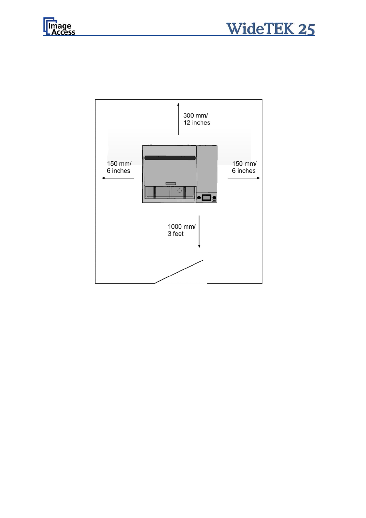
Please allow a minimum of 150 mm (6 inch) from any side walls and 300 mm (12 inch)
from a back wall. Leave one meter (3 feet) minimum distance from any door or entrance
way. Use the illustration below as a guide.
Picture 1: Minimum distances
Do not operate the scanner in an area that has poor air circulation and/or that is nonventilated.
Place the WideTEK 25 on a flat and solid base. The load bearing capacity of the base
must correspond to the device weight.
Placing the WideTEK 25 on the optional floor stand is recommended for the best
ergonomic position while using the scanner.
Choose a location that complies with the limits of temperature and humidity. Refer to the
technical specification.
Note: Before using the WideTEK 25 scanner in the new environment allow at least one
hour for temperature adaptation.
Temperature adaptation means:
A fast change from cold to warm environmental conditions can build up
condensation inside the housing. This will result in unfavorable scanned images
and could cause permanent damages to the unit.
Page 16 Manual
Page 17

A.6 Maintenance and Repair
Note: There are not any parts or components of the WideTEK 25 scanner which can
be repaired by the user.
All repairs and service works should be done by a trained technician only.
A.6.1 Cleaning
Important: Ensure that no liquids will penetrate into the device housing.
A.6.1.1 Surfaces
Use a soft, dampened cloth to clean the housing of the scanner. Recommended is a micro
fiber cloth.
A.6.1.2 Glass plate
Important: Do not use any cleanser with solvents to clean the glass plate!
The glass plate of the WideTEK 25 has a special non-reflective surface coating.
Clean the glass plate with an appropriate glass cleaner and use a soft cloth.
Recommended is a micro fiber cloth.
After cleaning dry the glass plate with a soft cloth.
Manual Page 17
Page 18
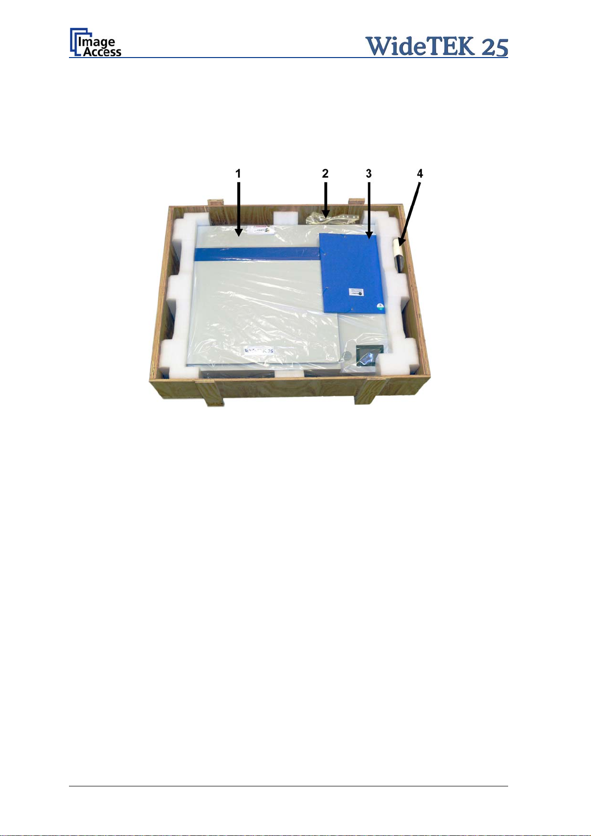
A.7 Content on Delivery
The scanner is delivered in a wooden transport box. The transport box also contains two
plastic bags, a folder with reference targets, and the manuals.
Picture 2 shows the transport box including all material which comes with the scanner.
Picture 2: Scanner WideTEK 25 in transport box
1: Scanner WideTEK 25.
2: Plastic bag with “Recovery Key” and cable set. The cable set consist of:
Network cable. Connects the scanner to the network. All network parameters such as
IP address, subnet mask and gateway must be set via the touch panel prior to the
first use.
Crossover cable. Connects the scanner directly to a computer via the network card.
Power cable. Connects the scanner to the wall outlet
3: Reference folder. It contains:
4x Color Scanner Test Target CSTT-1
4x Line Reference Sheet LRS-200
4: Plastic bag with 3x White Reference Targets WT36-Z-02-A.
Please note: Keep the wooden transport box for future use! In case of guarantee the
scanner must be sent back in the original transport box to avoid transport
damages.
Page 18 Manual
Page 19
A.8 Transportation Locks
A.8.1 Removing the transportation locks
Attention
The transportation locks have to be removed before initial start-up
of the device!
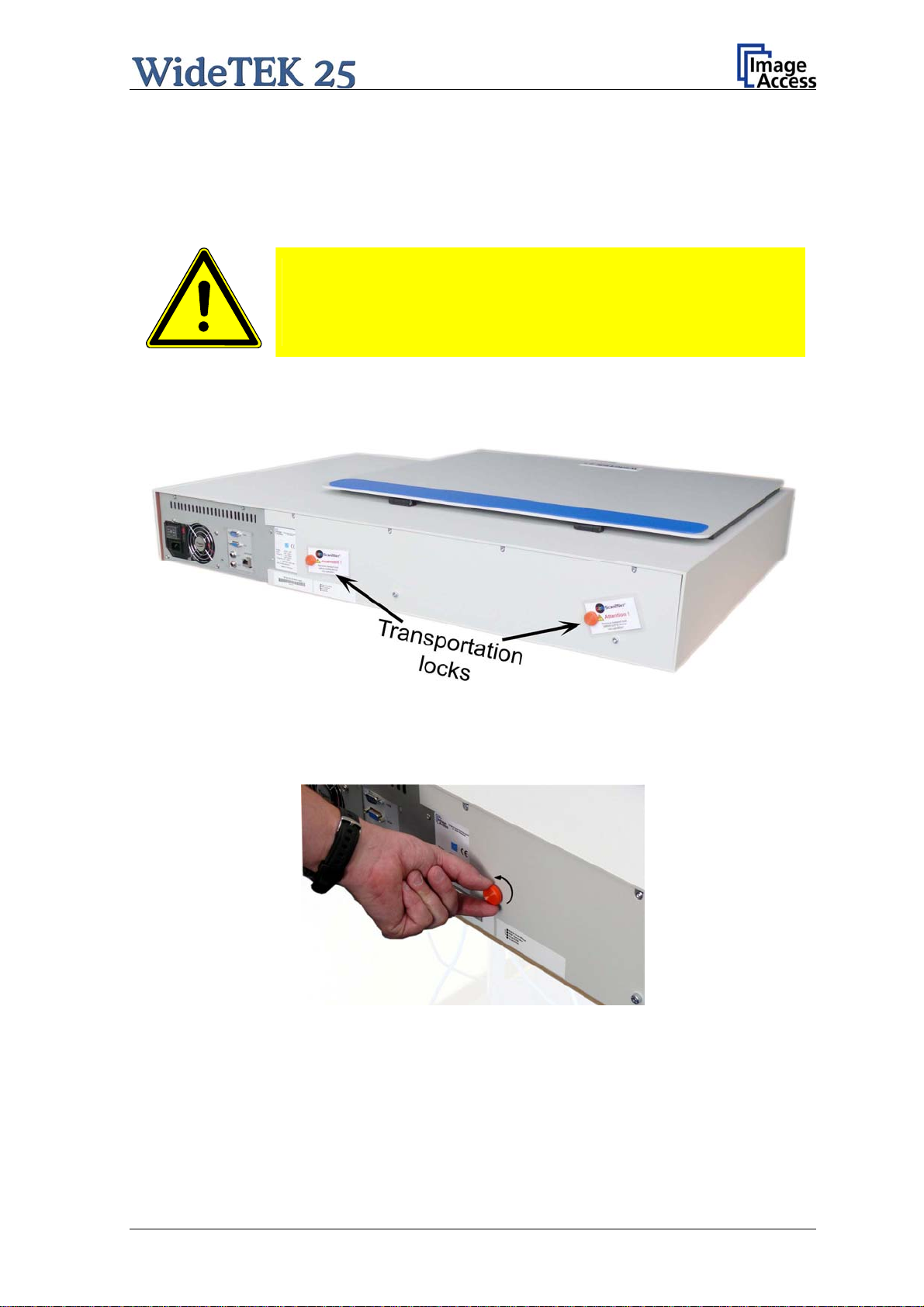
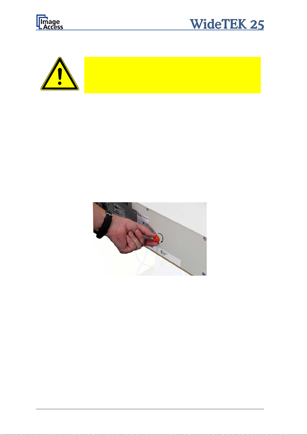
The transportation locks are located at the back of the scanner. A label marks each
transportation locks.
Picture 3: Position of transportation locks
Turn the transportation lock counterclockwise to remove it.
Picture 4: Removing the transportation lock
Important: Keep the transport lock for future use!
The transportation locks must be inserted before every transport. This will prevent the
sensitive components inside the camera box unit against damages.
Manual Page 19
Page 20
A.8.2 Inserting the transportation locks
Attention
Before transporting insert the transportation locks to prevent the
camera box unit against damages!
Before inserting the transportation locks the camera box unit must be moved into transport
position.
The transport position of the camera box unit is at the back side of the scanner – seen
from the operator’s position.
When the power down sequence ends normally, the camera box unit moves to its
transport position. If the camera box unit is in any other position after switching off, restart
the device as described in chapter A.11.1.
Afterwards turn it off as described in chapter A.11.2. The power down sequence moves
the camera
and switches the device to stand-by mode.
box unit to the transport position, finalizes all internal processes in the scanner
Switch off the WideTEK 25 at the main power switch (see Picture 7).
Picture 5: Inserting the transportation lock
Insert carefully the transportation locks which come with the scanner.
Hand-tighten by turning it clockwise. Using more force could result in damage of the
camera box unit.
Page 20 Manual
Page 21
A.9 Connecting to the Power Source
Before connecting the scanner to the electrical outlet check the following items:
Ensure the electrical outlet is in perfect condition and that it is
properly grounded.
Ensure that the electrical outlet is equipped with a fuse with the
proper capacity.
The electrical outlet must be near this device and must be easily
accessible.
Inspect the power cable and ensure that it is undamaged.
Use only the power cable delivered with the scanner.
Turn the device off before plugging or unplugging any cable.
All connectors are positioned at the right side of the back of the housing, seen from the
operator’s position (i.e. from the front of the scanner).
Manual Page 21
Page 22
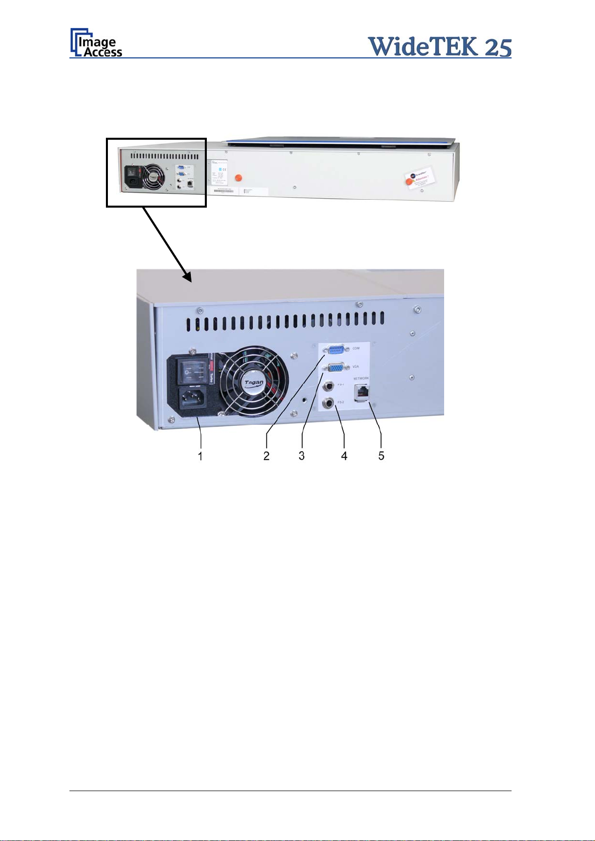
A.9.1 Connectors on the Back
Picture 6: Back of WideTEK 25
Picture 7: Connectors on the WideTEK 25
1: Power connector and main power switch
2: Serial connector
3: VGA conne ctor
4: Two foot pedal connectors
5: Network cable connector
Page 22 Manual
Page 23
A.10 Powering up the WideTEK 25
The main power switch is found above the power connector. Picture 7 shows the position
of the power connector and main power switch.
After connecting the scanner to the electrical outlet, switch the main power switch to
position I. When the main power switch is in position I, the scanner is in stand-by mode.
NOTE:
While using
only be switched on and off by the touch panel!
the WideTEK 25 in work conditions, it should
A.11 WideTEK 25 Touch Panel
The WideTEK 25 parameters can be set and modified with the integrated touch panel. It
shows an easy-to-use menu and helps the user to control all scanner parameters with the
touch of a finger.
When the WideTEK 25 is powered up using the main power switch, the touch panel is
illuminated in a dimmed mode and shows the stand-by screen. The stand-by screen
shows the Image Access logo and the blinking message Touch screen to power up.
A.11.1 Starting the WideTEK 25 from Stand-By Mode
When the WideTEK 25 is in stand-by mode, it can be started by tapping the touch panel
on any arbitrary position. The touch panel lights up and a rotating hourglass indicates that
the start sequence is running.
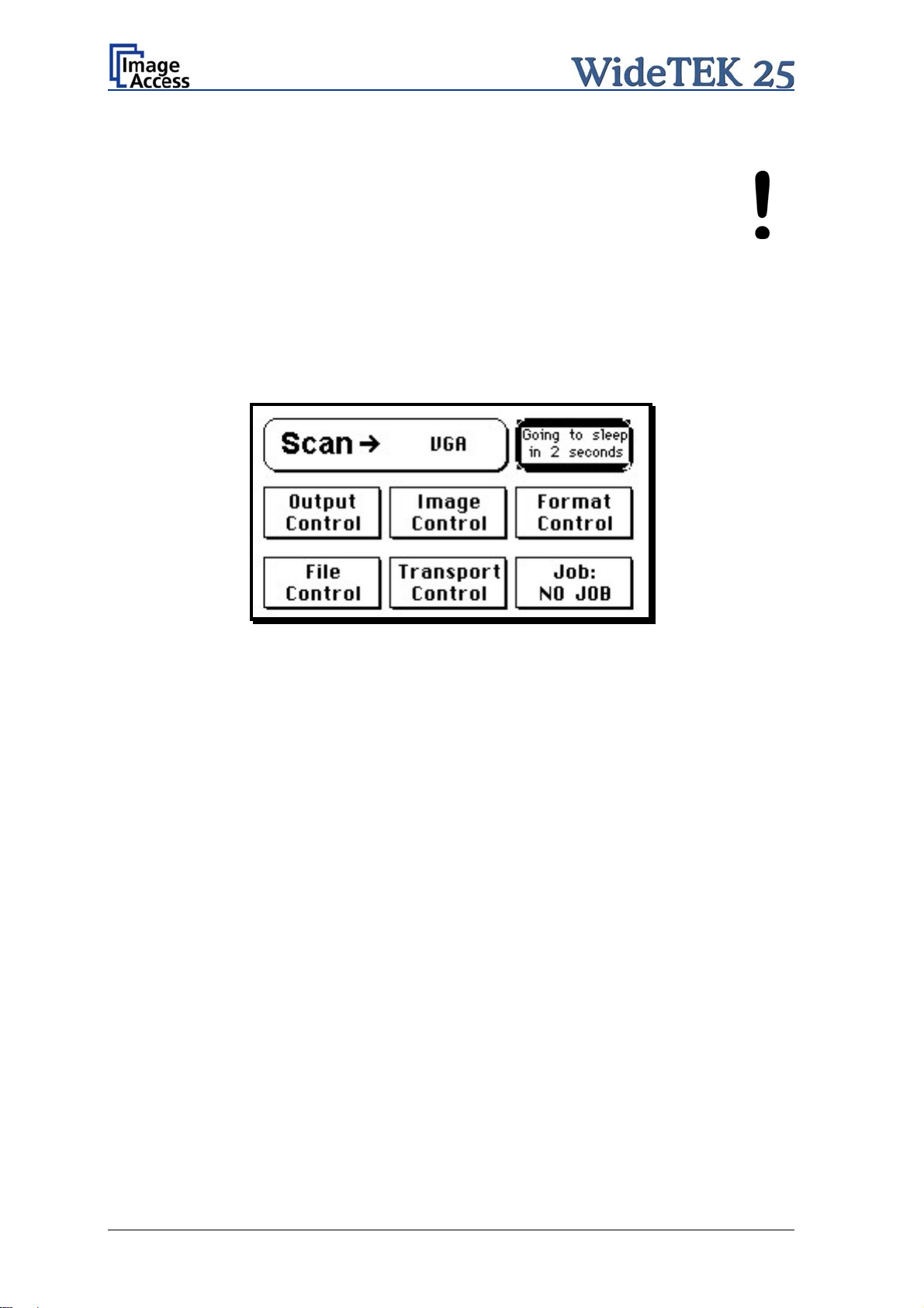
When the start-up sequence is finished, the touch panel shows the start menu screen.
Picture 8: Start menu screen
Manual Page 23
Page 24
A.11.2 Turning-off the WideTEK 25 by the Touch Panel
ays turn off the WideTEK 25 scanner with the Stop button on
NOTE:
Alw
the touch panel!
The main power switch should only
is in stand-by mode and before it is disconnected from the electrical
outlet.
To turn off t
While the Stop button is held, a counter in the button shows the remaining time until the
WideTEK 25 is powered down. “Going to sleep in x seconds”
At the end of the power down sequence, the display will be dimmed.
he WideTEK 25, press and hold the Stop button on the touch panel.
Picture 9: Touch panel while shut down in progress
be used when the WideTEK 25
A.11.3 The Help Function
To support the user when working with the WideTEK 25, a help function is integrated into
the touch panel menus. A Question Mark (?) symbol in the lower right corner of the
screen activates the help function.
After touching the question mark, all controls in the screen start blinking. To see the
corresponding help text, the appropriate control must be touched. To return to the
respective screen, the screen must be touched again on any arbitrary place.
Page 24 Manual
Page 25
A.11.4 Navigating through the Screens
Some of the screens show on the bottom line the buttons
Returns to the former screen. Somet
Switches to
the next logical screen, e.g. from Format Control 1 to
imes only the symbol < is displayed.
Format Control 2. Sometimes only the symbol > is displayed.
Resets all values in the
respective screen to default value.
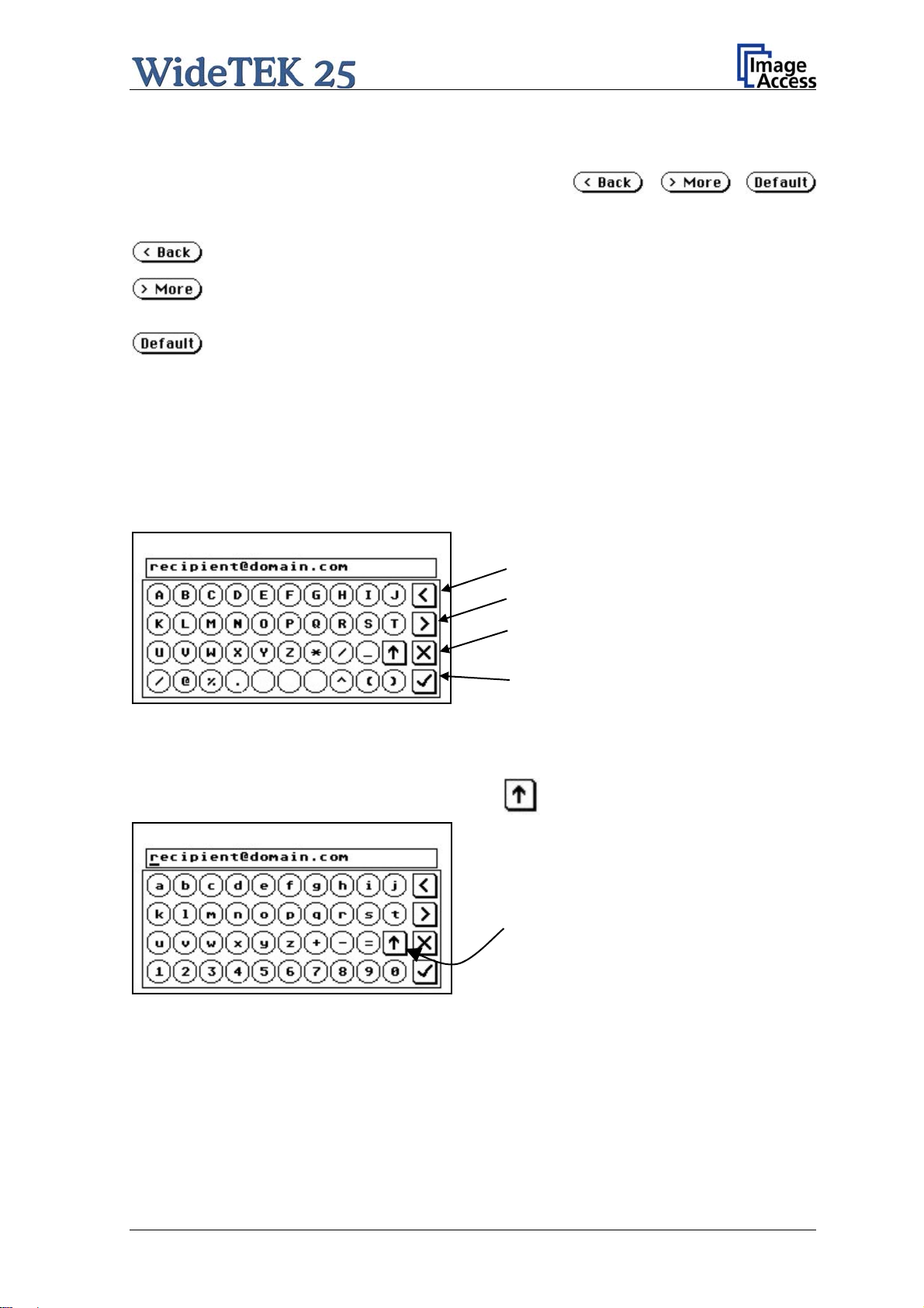
A.11.5 How to Enter or Change Values
To enter new values or change existing values, the corresponding field or line in the
screen must be touched. If a parameter requires an alphanumeric value, the touch panel
display changes and shows a keyboard with which text and numeric values can be
entered.
Moves cursor to the left.
ht.
he cursor
Picture 10: Keyboard with capital letters
Moves cursor to the rig
Erases the character at t
position.
Checkmark symbol returns to previous
screen.
The keyboard enables the user to enter capital letters, lower case letters, special
characters as well as numbers.
The content of the keys is switched with this key:
Toggles between capital letters and
special symbols (e.g. backslash or @)
and lower case letters and numbers.
Picture 11: Keyboard with lower case letters
Manual Page 25
Page 26
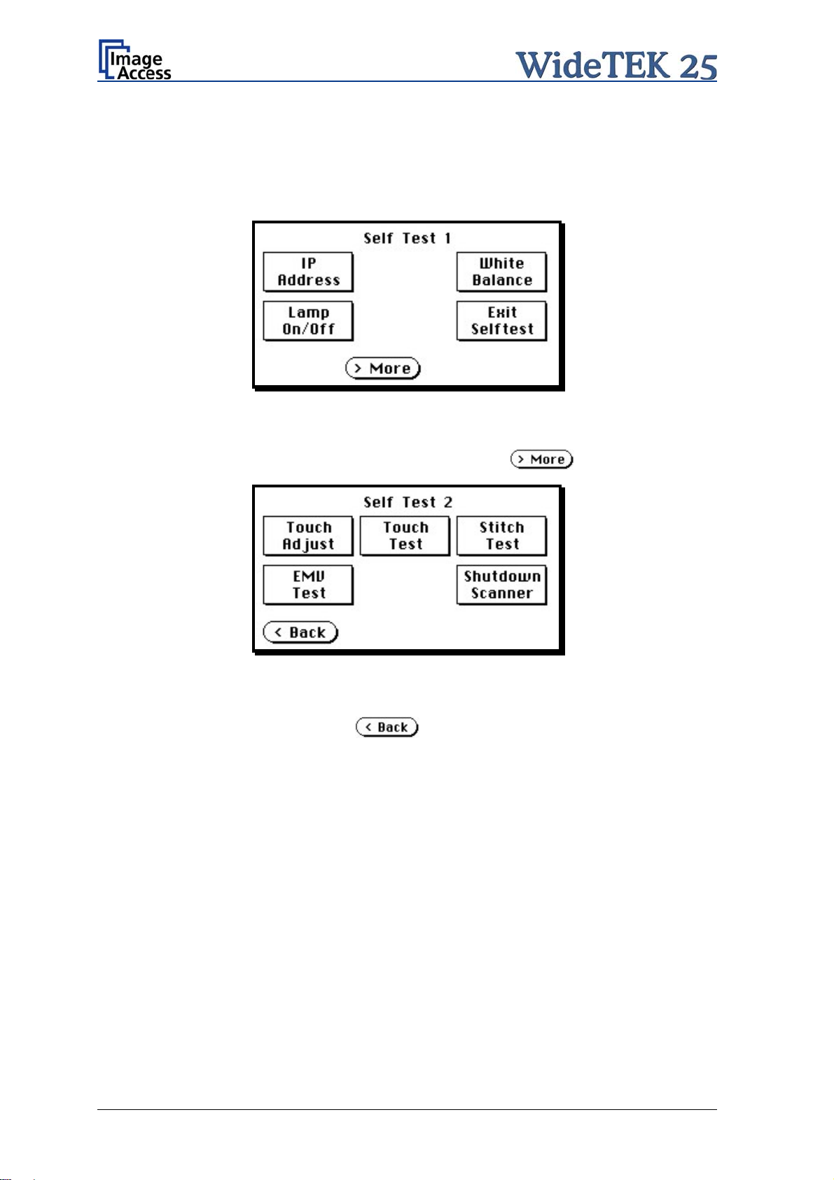
A.11.6 Self Test Mode
While the start sequence is running, the WideTEK 25 can be switched to Self Test mode.
Tapping on the touch panel at least three times starts the setup mode. After the start
sequence is finished, the touch panel shows the Self Test 1 screen.
Picture 12: Self Test 1
To move forward to the Self Test 2 screen touch the button
Picture 13: Self Test 2
To return to the former screen touch
.
.
Page 26 Manual
Page 27
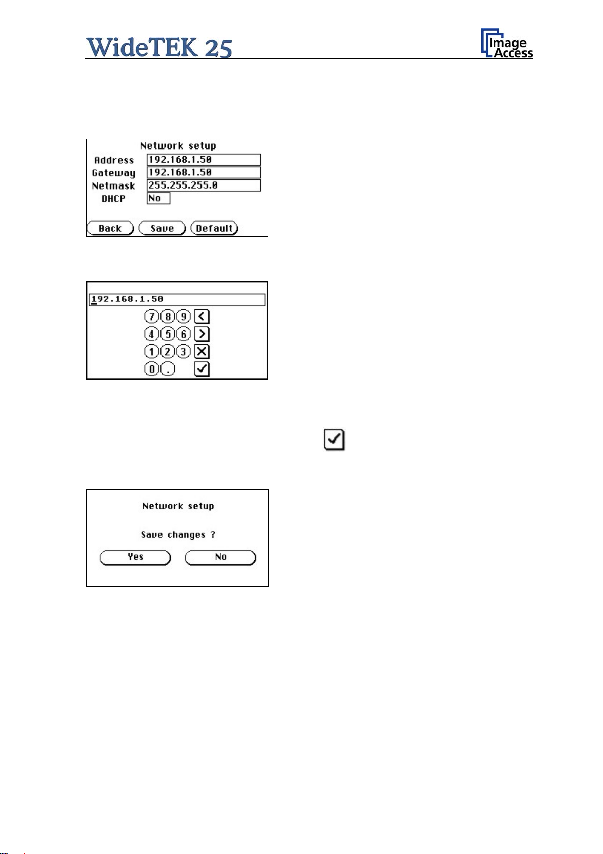
A.11.6.1 IP Address
Touch the control field IP Address. The touch panel changes to the Network setup
screen.
Picture 14: Network setup
Touch on the line to be changed, e.g. the Address line. The touch panel shows:
Picture 15: Numeric key pad
Enter the new values. The < and > keys move the cursor, the X key deletes the number at
the cursor position.
To finalize
the input tap on the checkmark key.
If entries have been changed, a screen opens where the changes must be confirmed.
Yes confirms the changes, No discards the changes.
Picture 16: Confirm changes
After the changes have been saved, the setup screen is displayed again.
Manual Page 27
Page 28
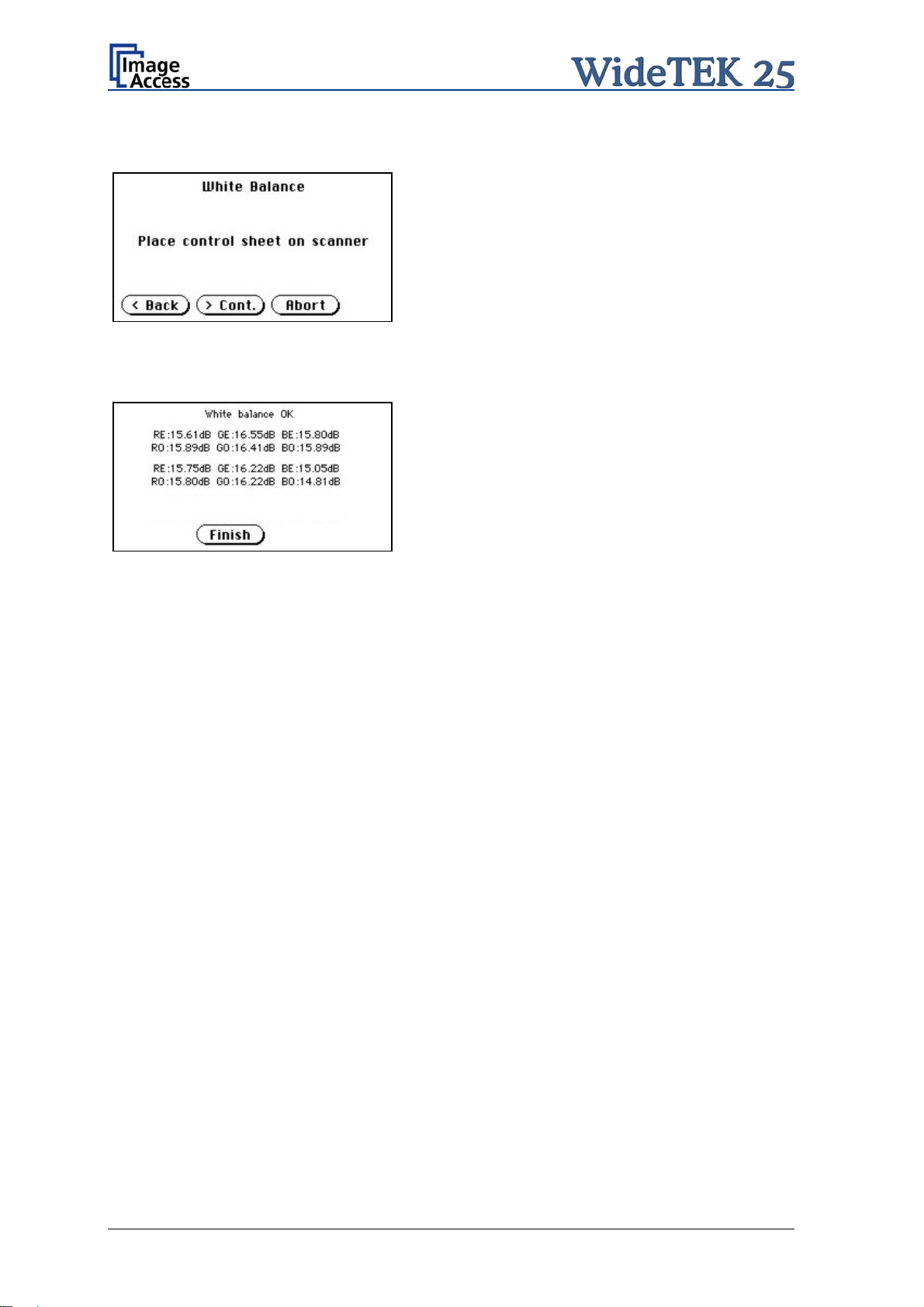
A.11.6.2 White Balance
Picture 17: Place the control sheet
Picture 18: Results of White Balance
Test
Touch the White Balance button t
o start the
white balance measurement sequence. Place the
white reference sheet on the upper edge of the
glass plate. The white reference sheet must
cover the complete width of the glass plate. Then
touch the Cont. button.
The measurement lasts a short time.
The Abort button returns to the previous screen
if the white balance measurement should not be
executed.
After the white balance has been finished, the
result is displayed
Touch the Finish button to return to the
Self Test 1 screen.
A.11.6.3 Lamp On / Off
Touch the Lamp On / Off button to switch the lamps on. As long as the button is touched,
the lamps will shine.
A.11.6.4 Exit Selftest
Touching Exit Selftest finalizes the setup mode, switches to the operation mode and
shows the start menu.
Page 28 Manual
Page 29

A.11.6.5 Touch Adjust
This function defines the dimension of the writing area of the touch panel. The first step
after selecting this function must be done very quickly to activate the adjustment
procedure.
Note: It is recommended to read first, then act. It is recommended to use for the
following adjustment steps an appropriate pen, e.g. as used with a PDA.
Touch the Touch Adjust button, then press and hold the touch panel. The first message
on the screen can be ignored.
After a short moment a blinking dot appears at the upper left corner of the touch panel and
the instruction Touch this blinking dot is displayed. Touch the blinking dot with the tip of
a suitable pen.
In the next step the instruction changes to the lower right corner. Repeat touching the
blinking dot in the lower right corner. After this, the touch panel returns to the Self Test 2
screen and the setup procedure is finished.
It is recommended to check the adjustment with the Touch Test function.
A.11.6.6 Touch Test
Touch Test is used to check the correct function of the touch panel.
Picture 19: Testing the touch panel
After selecting this function the display changes to a blank area.
By using an appropriate pen, e.g. as used with a PDA, write some symbols or lines on the
touch panel. While writing, check the correlation between the pen’s position and the
position of the signs that have been written.
If the difference is to large, repeat the adjustment as described in chapter A.11.6.5.
To return to the prior scr
een, touch the button
Manual Page 29
Page 30
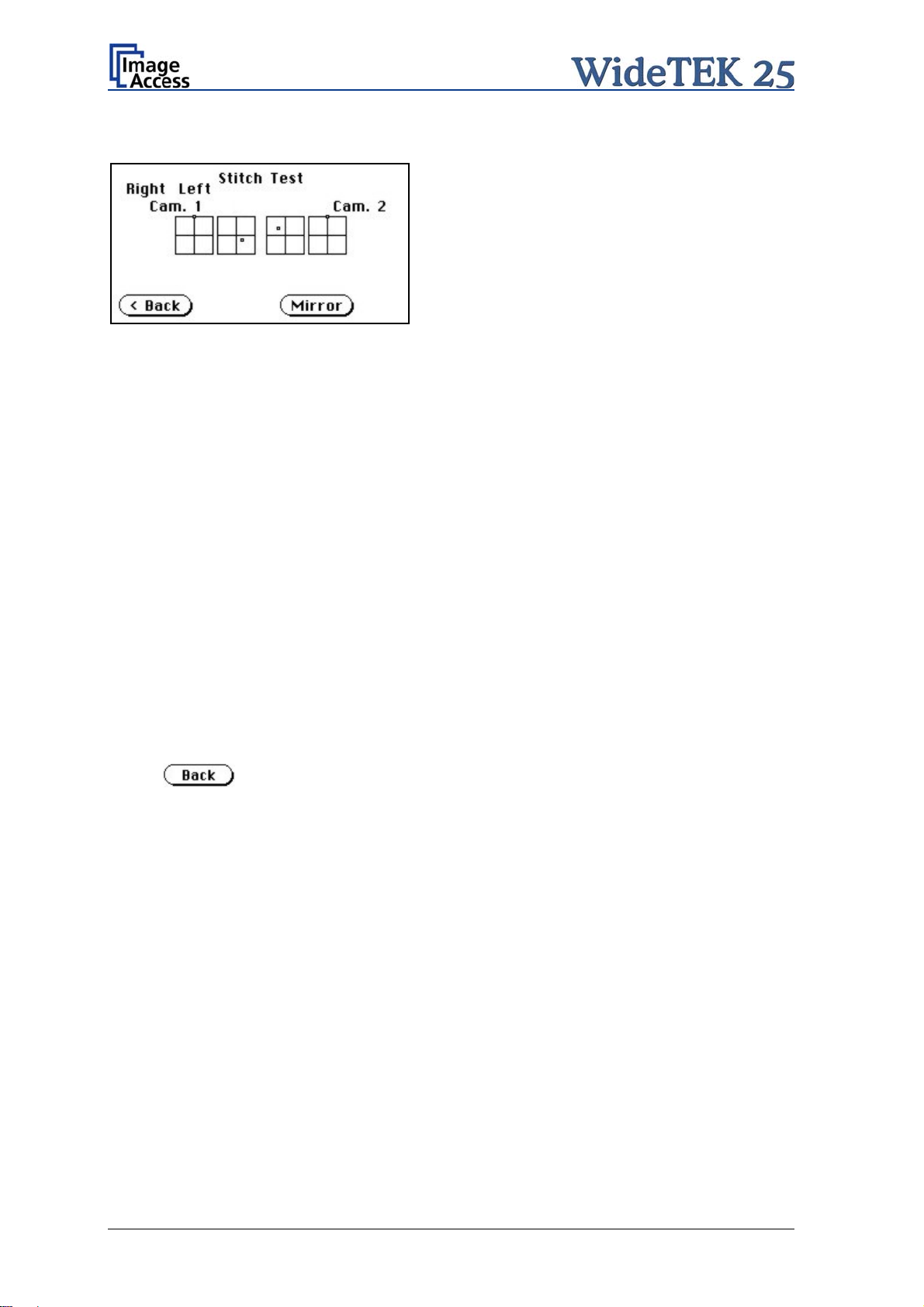
A.11.6.7 Stitch Test
Picture 20: Stitch Test screen
Press the Stitch Test button to start the stitch test. This starts a program in which you can
see an automatically updated view of the stitching indicators for each camera. The
measurement will be executed continuously, once every second.
The cameras left and right are identified as the left and right cameras when looking at the
scanner from the operator’s view (i.e. from the front of the scanner). Each camera has a
set of two stitching coordinate boxes. A stitching coordinate box consists of four
quadrants.
Picture 20 shows a typical situation of the stitching indicator
s. That means, that all camera
settings are within the specified tolerances.
Ideally, the stitching indicators (the small dots inside the four-quadrant boxes) should be
positioned close to the center of the crosshairs.
If a stitching adjustment is necessary, it must be done by a trained technician.
A.11.6.8 EMV Test
This function is used for Electromagnetic Compatibility (EMC) tests.
After inserting a test document into the scanner, the scan sequence is repeated until the
button is pressed.
A.11.6.9 Shutdown Scanner
Switches the WideTEK 25 scanner off.
Page 30 Manual
Page 31

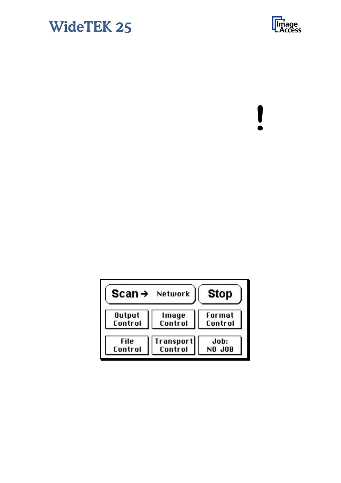
A.11.7 Start Menu Screen
Picture 21: Start menu screen
When all initial tests are finished, the display shows the start menu screen.
At the top of the start menu, the main controls to start a scan sequence and to stop the
current action are displayed.
The scanned image can be directed to different targets.
The selected target is named between the Scan and the Stop button. Picture 21 shows
as selected
target the network in which the scanner is integrated.
The controls in the middle line and in the lower line of the menu are used to configure the
parameters in detail.
Manual Page 31
Page 32

A.11.8 Output Control Sc reen
Picture 22: Output controls
A.11.8.1 FTP Server
The “Ftp Server” button on the Output Control menu enables the user to enter all
necessary information for data transfer to a dedicated FTP server. The parameters are
entered in two screens named Ftp Server 1 and Ftp Server 2.
A.11.8.1.1 Ftp Server 1
This screen
contains the server IP address and the port, the user name and the password
for the server access. Additionally a path to an existing directory on the FTP server where
the files should be stored can be entered.
Returns to the previous screen.
Changes to the Ftp Server 2 screen.
Picture 23: Ftp Server 1
Note:
The IP address 127.0.0.1 (as shown in the above picture) does not represent a
real existing FTP server. This IP address is typically used in networks to make the
own system, the so-called “localhost”, available for TCP/IP applications.
Page 32 Manual
Page 33

A.11.8.1.2 Ftp Server 2
This screen contains all data for the connection with a FTP server.
Stores all parameters.
Erases all changes.
Picture 24
: Ftp Server 2
Use prox
y Select Yes to use a proxy server for the connection.
Auth. Defines the type of authentication at the FTP server. By tapping on the
field the methods will be switched.
Anonymous: An anonymous connection will be used. The data in the fields
User and Password from the FTP Server 1 mask will be
ignored.
Login/Password: To save the images on the FTP server a login name and a
password must be entered.
Ask the administrator of your FTP server for the necessary information to get access to
the designated FTP server.
Manual Page 33
Page 34

A.11.8.2 Email Address
This menu item enables the user to send the scanned image to any arbitrary e-mail
address.
Picture 25: E-mail address parameters
To store all entries of this menu touch the button .
A.11.8.2.1 Input an E-Mail Address
Tap on the line of the e
Picture 10 and Picture 11. Enter the desired e-mail address. The @ symbol is found on
the keyboard in the capital letter layout in the bottom line.
-mail address. The screen changes to input mode as shown in
To delete a character place the cursor below the character and tap on the X key.
When the complete e-mail address is entered, tap on the checkmark key to return to the
previous screen.
To store the values touch the button
To return to the former menu, touch the button
If entries ha
ve been changed, a screen opens where the changes must be confirmed.
.
Yes confirms the changes, No discards the changes.
Page 34 Manual
Page 35

A.11.8.3 Windows Network
Allows the user to
define the network path where the image should be stored,
the define the authentication method,
define the user name,
define the password,
define the filename
Picture 26: Network parameters
To store all entries of this menu touch the button .
A.11.8.3.1 Input a Network Address
Picture 27: Input a Network Address
Tap on the line of the network path name. The touch panel screen changes and displays
the keyboard layout.
The slash symbol / is found on the keyboard in the capital letter layout in the bottom line.
To delete a character place the cursor below the character and tap on the X key.
When the complete network address is entered, tap on the checkmark key to return to the
previous screen.
To store the values touch
.
To return to the former menu, touch the button .
If entries ha
ve been changed, a screen opens where the changes must be confirmed.
Yes confirms the changes, No discards the changes.
Manual Page 35
Page 36

A.11.8.4 Viewer Control
An external monitor can be connected to the WideTEK 25 to show the scanned image
directly.
Touching the Viewer Control button starts the Zoom/Move Control mode. When this
mode is active, the displayed image on the screen can be moved and the zoom factor can
be changed.
Navigation
keys
Picture 28: Viewer Control
Increases the zoom factor.
Decreases the zoom factor.
Zooms the image to its genuine dimension (100%) without scaling.
Returns to the prior menu.
If the image dimension overlaps the monitor dimension, the navigation keys can be used
to scroll the displayed area on the monitor.
Page 36 Manual
Page 37

A.11.8.5 Sound Control
The menu item Sound Control allows the user to link sounds to system events.
Picture 29: System events and sound files
To select a system event, touch the scroll bar in the left window or the up/down arrows.
The currently selected sound file associated with this system event will be displayed in the
right window.
To select a different sound file from the list, touch the up/down arrows or the scroll bar in
the right window until the sound file to be used is marked in reverse color.
To modify the sound volume, move the scroll bar between the loudspeaker symbols up- or
downwards.
Returns to the prior menu.
Links the system event and the marked sound.
Plays the sound which is marked in reverse color.
Manual Page 37
Page 38

A.11.9 Image Control Screen
The parameters are set in two screens named Image Control 1 and Image Control 2.
A.11.9.1 Image Control 1
Picture 30: Image Control 1
In general:
Tap the + or – to change the values in steps of one.
Tap the + or – and hold for at least five steps, then the value changes in steps of five.
A.11.9.1.1 Brightness
The brightness control
defines the resulting brightness of the image. A lower value results
in darker images, a higher value results in brighter images.
Values close to 0% or 100% may result in unwanted artifacts.
A.11.9.1.2 Contrast
The contrast control def
ines the contrast of the image. A lower value results in an image
that is smoother, a higher value shows more details and the image will become crisper.
Values close to 0% or 100% may result in unwanted artifacts.
A.11.9.1.3 Gamma
The gamma control defines the gamma
correction used by the scanner camera. A value
of 1,6 is a good approximation. The range of values are from 0 (no gamma) to 2,5
(maximum gamma).
A higher gamma value shows more details in darker areas and compresses bright areas.
Page 38 Manual
Page 39

A.11.9.1.4 Sharpness
An automatic sharpening algorithm is applied to the image before any other operation is
performed.
The value zero disables the function. Very high values may produce artifacts, depending
on the document characteristics.
A.11.9.1.5 Resolution
This parameter defines the scanner’s resolutio
n. This button offers three ways to set the
desired value:
Tap the + or – to change the resolution in steps of one DPI.
Tap the + or – and hold for at least five steps, then the value changes in steps of five
DPI.
Tap the numeric value in the middle of the button. This will step through the list of
available resolutions.
A.11.9.1.6 Color mode
The color mode parameter defines t
he color mode if scanning in color or the algorithm
used for binarization in binary mode.
24b color 24 bit color mode
8b color 8 bit color mode
Grayscale 8 bit grayscale mode
Binary 1 bit black/white mode
Photo 1 bit black/white mode with dithering. Dithering means that finest details in
the image are optimized by rastering.
This control also influences the compression method that is offered in the File Control
screen.
Chapter A.11.4 gives information about the buttons
.
Chapter A.11.3 gives information concerning the help function, which is activated by the
Question Mark symbol.
Manual Page 39
Page 40

A.11.9.2 Image Control 2
Picture 31: Image Control 2
Note: Depending on the selected color mode, some buttons may not be displayed.
A.11.9.2.1 Threshold (only in Binary mode)
Defines the
Available modes are Fixed and Auto.
contrast control mode.
Fixed: The contrast is fixed to defined value.
Auto: The contrast of the image set dynamically, depending on the values found in
the image. This can be used to improve delicate details in the image.
A.11.9.2.2 Despeckle (only in Binary mode)
Remo
ves isolated pixel in the images.
Available modes are 4x4p and Off.
A.11.9.2.3 Invert (only in Binary and Photo mo
de)
Inverts the displayed image.
A.11.9.2.4 Stitching
Defines the
stitching method which is used to merge the image data to one image.
Fixed: Merges the image data at a specified offset area.
Adapt.2D: Merges the image data dynamically.
A.11.9.2.5 ICC Profile
ICC profiles add color co
rrection values to each scanned image.
Page 40 Manual
Page 41

A.11.9.3 Image Control 3
Picture 32: Image Control 3
Note: Only in the color modes 24b color, 8b color, and Grayscale.
A.11.9.3.1 Exposure
Defines the
Available are Black Cut, Auto and Fixed.
exposure correction mode.
Black cut All color values in the image which are below the threshold for black are
displayed as black.
Auto Activates the threshold for black and the automatic brightness control.
Automatic brightness control means the brightness range of the image is
expanded to the maximum range of the scanner. This converts the darkest
areas of the image to solid black and the brightest areas to solid white.
Fixed Switches off the exposure correction mode.
A.11.9.3.2 Exp. Black
Defines the
value for the threshold for black.
Chapter A.11.4 gives information about the buttons
.
Chapter A.11.3 gives information concerning the help function, which is activated by the
Question Mark symbol.
Manual Page 41
Page 42

A.11.10 Format Control Screen
The parameters are set in two screens; Format Control 1 and Format Control 2. By
using the Back and More buttons, you can switch between the Format Control screens.
A.11.10.1 Format Control 1
Picture 33: Format Control 1
A.11.10.1.1 Format
This control specifies the format of the document. In most cases the setting Auto should
be selected.
The format list includes the well known DIN A formats as well as US ANSI formats, e.g.
Letter or US C. Some formats are specified with an additional L(andscape) or P(ortrait).
A.11.10.1.2 Doc shape
Defines the
documents structure. Flat is currently the only available setting.
A.11.10.1.3 Start page
This define
s the start page if Splitting is activated.
A.11.10.1.4 Rotation
The value
set here defines the rotation of the image in a clockwise direction after
scanning.
A.11.10.1.5 Mirror
This control
activates the horizontal mirroring of the image.
It can be useful if scanning a transparency or a blueprint from the back side.
A.11.10.1.6 Splitting
The followin
g options are valid:
Left: The image is taken from the left side of the specified area.
Right: The image is taken from the right side.
Auto: Divides the specified scan area symmetrically into two sides and sends the
images consecutively. The second image will be sent without scanning the
document again.
The start is defined in Start Page (see chapter A.11.10.1.3).
Page 42 Manual
Page 43

A.11.10.2 Format Control 2
Picture 34: Format Control 2
A.11.10.2.1 Auto margin
The Auto margin control detects the edges of a document and cuts it out of the scanned
image.
If the value (in pixels) is negative, the resulting image will be smaller than the document.
This is helpful to remove unwanted borders from the image.
If the value is positive some of the background will remain in the scanned image.
A.11.10.2.2 Auto density
The Auto density function detect
s the edges of a document only if they are surrounded
by a dark background.
This control specifies the density level used to decide whether a pixel belongs to the
background or not. A value of 40 is the proper setting in most cases.
Note: When scanning very dark documents, it could be necessary to vary this value to
detect the correct document dimension with the format setting Auto (see chapter
A.11.10.1).
A.11.10.2.3 Auto skew
The image of the scanne
d area will be deskewed before it is displayed.
Auto skew enables the deskew function and defines the maximum angle of the document
to be deskewed.
Chapter A.11.4 gives information about the buttons
.
Chapter A.11.3 gives information concerning the help function, which is activated by the
Question Mark symbol.
Manual Page 43
Page 44

A.11.11 File Control Screen
Picture 35: File Control
The control File format specifies the file format of the image file. Depending on the
selected file format all other controls in this screen vary. The list of formats includes
JPEG, TIFF, PNM, and PDF (if the option is installed).
A.11.11.1 JPEG
When selecting the file format JPEG the functions of the controls are:
JPEG quality: Defines the compression. The JPEG quality level is defined with this
control. A higher percentage gives better quality but the file size will
increase. A lower factor will show some artifacts in the image but the
file size will be reduced.
Prev. quality: The JPEG quality level used for the preview is selected here. A higher
percentage gives better quality but the file size will increase. A lower
factor will show some artifacts but the file size will be reduced.
Prev. scale: This control defines the preview scale factor. Higher values result in
smaller previews; lower factors will produce larger previews but take
more time to send and display.
Page 44 Manual
Page 45

A.11.11.2 TIFF
When selecting the file format TIFF the functions of the controls are:
Note: Depending on the selected color mode in Image Control the available
compression methods vary.
TIFF compr.
None: Available with all color modes.
JPEG: Available with “24b color” and “Grayscale”. Additionally the controls
“JPEG quality” and “Prev. quality” will be displayed.
CCITT G4: Available with “Photo” and “Binary”.
Prev. scale: This control defines the preview scale factor used. Higher values result
in smaller previews; lower factors will produce larger previews but take
more time to send and display.
A.11.11.3 PNM
When selecting the file format PNM only the preview scale can be selected.
Manual Page 45
Page 46

A.11.11.4 PDF
When selecting the file format PDF the functions of the controls are:
JPEG quality: Defines the compression rate. The JPEG quality level is defined with
this control. A higher percentage gives better quality but the file size
will increase. A lower factor will show some artifacts in the image but
the file size will be reduced.
Prev. quality: The JPEG quality level used for the preview is selected here. A higher
percentage gives better quality but the data size will increase. A lower
factor will show some artifacts but the data size will be reduced.
Prev. scale: This control defines the preview scale factor. Higher values result in
smaller previews; lower factors will produce larger previews but take
more time to send and display.
PDF compr: “None” disables the data compression. The controls “JPEG quality”
and “Prev. quality” will not be displayed.
“JPEG” enables the data compression. The controls as shown above
will be displayed.
Chapter A.11.4 gives information about the buttons
.
Chapter A.11.3 gives information concerning the help function, which is activated by the
Question Mark symbol.
Page 46 Manual
Page 47

A.11.12 Transport Control Screen
Picture 36: Transport Control
A.11.12.1 Start button
The Start button defines the start method of the scanner.
Direct: The scan starts when the scanner receives the start command from the
application.
Wait: The scan will only start if the start button is pressed. The start button can also be
a foot pedal.
A.11.12.2 Bidir. scan
The Bidir. scan button defines the scan direction of the scanner.
On: The scanner scans in both directions (bidirectional). This increases the
document throughput while scanning documents of similar dimensions.
Off: The scanner always starts scanning from its zero position. This setting is
recommended if the dimension of the documents vary.
Manual Page 47
Page 48

A.11.13 Job
Picture 37: List of available jobs
The control Job allows the user to create and store specific settings of the scanner. This
is useful if the scanner is operated by several users with different settings for document
size, resolution or other parameters.
A.11.13.1 Creating a Job
Creating a “job” is done in a few steps.
First, the job settings have to be specified; i.e. definition of document size, resolution, file
format etc. When all settings have been specified, tapping on Job in the
Start Menu Screen opens the screen displayed in the picture above.
Tapping in the line Job name will o
screen with the keyboard. Here the job name can
be entered. The new job name must be
confirmed with the checkmark button.
Picture 38: Keyboard of input screen
Refer to chapter A.11.5 for get more information how to handle the keyboard.
pen the input
Page 48 Manual
Page 49

Picture 39: Creating a job
Picture 40: Entering the password
Tap on Create to save the job.
Tap on with password to save the job in
combination with a password.
Tap on Cancel to cancel procedure.
If a password should be used, tapping on the
button with password opens a screen as shown
in the picture on the left.
Tapping in the empty field opens the screen with the alphanumeric keyboard (Picture 38).
Enter the password.
Tap on the checkmark button in the alphanumeric keyboard to confirm the password and
to return to the former screen.
The screen now shows the number of elements
of the password.
Tapping on Ok returns to the list of available jobs
(Picture 37).
The job is n
Picture 41: Number of password elements
ow active.
If no password for the job is necessary, tapping on Create opens a screen where the
operator is asked to confirm the new job name. This is easily done with the Yes button.
Manual Page 49
Page 50

A.11.13.2 Selecting a Job
New job names are added to the list of available jobs.
Jobs can b
e selected from the list of available
jobs by tapping on the selection arrow or directly
on the job name.
Tapping the Select button activates the job.
Selecting a password protected job opens a
screen where the operator must enter the
password. Tapping in the empty field opens the
alphanumeric keyboard and the password can be
entered.
Tapping on the checkmark button finalizes the
input sequence.
After the password is entered, the screen shows the Select job screen (see above) again.
Tapping on the Ok button finally selects the job and returns to the Start Menu Screen.
A.11.13.3 Deleting a Job
Select the job to be deleted from the list of available jobs.
Tap on the Delete button.
In the next screen, ta
delete the job.
If the job is password protected, the password
must be entered first. After selecting the job to be
deleted, a screen opens where the password is
entered.
Tap on the empty field. The screen with the
alphanumeric keyboard opens. Enter the
password and tap on the checkmark button to
finalize the input sequence.
In the next screen tap on Ok.
p on the Yes button to
The screen
returns to the Start Menu Screen.
Page 50 Manual
Page 51

A.11.14 Software Option: Scan2VGA
An external monitor can be connected to the WideTEK 25 to show, edit and save the
actual scanned image on the fly.
When the scan sequence has been finished the menu in the touch panel changes.
By tapping at the respective buttons the menus
can be sele
cted.
Picture 42: Scan2VGA
With touchin
Scan settings which made
changed here again and the results are shown
directly at the external monitor.
The edited image can be saved by touching the
Save button. Available targets are:
Network
USB
Printer
FTP
Email
g the Exit button the mode will be left.
before can be
Manual Page 51
Page 52

B Software
Essentially, the scanner is a web server and comes with its own HTML-based user
interface. To access a Scan2Net scanner, any standard web browser can be utilized.
B.1 Start Screen
Start your browser.
Enter the IP address of the scanner. The default IP address of the scanner: 192.168.1.50
The start screen of the integrated user interface will be displayed.
Picture 43: Start screen
Launch Scan Application switches to the main screen. Detailed information will be found
starting in chapter B.2.
Setup Device switches to the setup menu. Detailed information will be found starting in
chapter B.5.
Information gives a short summary of the device parameters. Information will be found
in chapter B.4.
Page 52 Manual
Page 53

B.2 The Main Screen
After launching the scan application, the main screen of the integrated user interface will
open. The main screen is structured in three parts. Switching between the sections is
done with a mouse click.
Picture 44: Main screen
1: The menu bar of the large frame on the upper right part has five menu items:
Options
Properties
Camera
Settings
Format
Click at a menu item to select and set parameters of the scanner.
Manual Page 53
Page 54

2: The eight control buttons in the lower part of the screen control the output modes.
As default the output mode Show is selected. After clicking onto the button Preview or
onto the button Scan Now a window opens and shows the image.
When selecting Save the scanned image will not be displayed. Instead of the second
window a box opens where the desired directory can be set.
Selecting Print will display the scanned image in a second window and direct the
scanned image to locally available printers.
Selecting Copy prints directly to a previously installed network printer.
Selecting FTP Upload scans directly to a FTP server.
Selecting Mail sends the scanned image directly to a previously defined e-mail
address.
Selecting Network uploads the scanned image directly to a previously defined
workstation in the network.
Selecting USB the scanned image is stored on an USB stick. A USB stick can be
connected to the scanner at the connector at the front side.
3: The frame on the left side shows the buttons for preview scan (Preview) and main
scan (Scan Now).
Pressing this button switches the scanner off.
If the red button is pressed, the following window will appear.
Picture 45: Shutdown confirmation
Click on the button Shutdown and the scanner switches off.
Page 54 Manual
Page 55

B.2.1 The Options Screen
Picture 46: Options screen
The Document Mode allows the user to select between different types of documents.
Currently the only mode is Flat Mode. In this mode the scanner works with a fixed focus
setting, regardless of the actual shape of the document.
The Preview Scale selector will be used for previews. If set to Auto, the function will
perform a best fit before the image is displayed on the screen.
The Preview JPEG Quality (%) determines the compromise between quality and
compression rate. A higher quality factor produces larger files. The default setting of 40 is
a good compromise for most documents.
The Bidirectional Scan allows two settings:
Bidirectional Scan: Yes: The camera scans the selected scan area size and stops at
the position where the scan area ends. The next scan
sequence starts from this position in opposite direction.
Bidirectional Scan: No: The camera scans the selected scan area size and returns to
its initial start position. While the camera returns to the start
position the document can be changed.
Manual Page 55
Page 56

Image Rotation
The image can be rotate
d before it is displayed.
The rotation can be any degree of out of 90°, 180°, 270° or none. The
angle is defined in the clockwise direction.
Click on the selection arrow and select the rotation angle from the list.
The Embedded ICC switch is either Yes or No.
The Embedded Meta Data switch is either Yes or No.
Clicking the Option link opens a window, where the
embedded metadata can be entered.
The Mirror function can be set to None or Horizontal or Vertical.
Page 56 Manual
Page 57

B.2.2 The Properties Screen
Picture 47: Properties screen
The Color Mode allows the user to select various color modes. 24bit Color, 8bit Color,
Grayscale, Binary and Photo are available color modes.
The available color modes are displayed in the picture on
the left.
To select a color mode first click on the selection arrow, then
select a mode from the list.
Manual Page 57
Page 58

The File Format defines the file format that is used to store a scanned document.
Note: There are some interdependencies between Color Mode and File Format.
That means, it is not possible to combine all color modes with all file formats.
For example, an image scanned in “24bit Color” can not be stored in TIFF file
format with TIGG G4 compression.
Depending upon the selected file format, the control beside it can vary:
Example:
Color Mode 8bit Color, File Format TIFF
TIFF Compression is d
isplayed
additionally.
Picture 48: 8bit Color
The Stitching selector
defines the method for the merging of the data of the cameras.
Fixed Select this setting when scanning documents with a plain surface
without crinkles or when a short scan time is important.
Adaptive 2D Default setting.
Select this setting when scanning documents with uneven structured
surface, e.g. multiple folded paper. The image data will be merged
dynamically. The time until the image is displayed will increase a little.
Page 58 Manual
Page 59

The Splitting Image function allows the operator to split the image of the scanned
document.
Off: No page splitting.
Auto: The first image is taken from the side which is defined in
the setup menu as start page. Click on Preview or Scan
now again to get the other half.
Left: The image is taken from the left half of the specified area.
Right: The image is taken from the right half of the specified
area.
The Format list offers various standard paper formats.
If Auto is selected, th
e scanner scans the complete document and then crops the
document to its real size. This function is highly advanced and works with default values
most of the time.
If User is selected the User defined format control opens. It allows to
set the values for Height and Width of the area to be scanned. It also
allows to define the position of the area to be scanned. The position is set
by the values for X Offset and Y Offset.
Note: The point of origin for X Offset and Y Offset is defined in the
upper left corner of the document area. Only positive values are allowed.
Picture 49: User Defined Format
Manual Page 59
Page 60

An Additional Margin [mil] can be added to or taken away from the image.
Picture 50: Additional Margin/Auto Density slider
The margin is defined in mil (1/1000 inch). The desired value can be entered as a
numeric value or by clicking on the slider and moving it to the desired value. If a numeric
value us entered, confirm the input with the ENTER key or the TAB key on the PC
keyboard.
The Auto Density (Binary) parameter defines the scanner’s sensitivity for the automatic
format detection. Default value: 40
When scanning dark documents, the value should be reduced in small steps until the
desired result is achieved.
In general: The higher the numeric value, the more contrast there must be between
background and scanned document.
The Use Deskew control activates the automatic deskew function.
If Yes is selected, a slid
er is displayed which
allows to set the maximum corrected angle.
Picture 51: Set deskew angle
The desired
value can be entered as a numeric value or by clicking on the slider and
moving it to the desired value.
If a numeric value us entered, confirm the input with the ENTER key or the TAB key on
the PC keyboard.
Page 60 Manual
Page 61

B.2.3 The Camera Screen
Picture 52: Camera screen
The Resolution field allows the operator to set the desired resolution in two ways.
Selecting the resolution: Click the selection arrow beside the right field. Select the
desired value from the list.
Entering the resolution: Enter any value between 150 dpi and 1200 dpi into the left
field. Confirm the input with the ENTER key or the TAB key on
the PC keyboard.
If the entered resolution differs from the values offered in the
list, user defined is displayed in the right field.
The Brightness [%] slider defines the brightness of the resulting image. Lower brightness
values make the image darker.
The Contrast [%] slider defines the contrast of the resulting image. Higher contrast
values show more details. If scanning in binary modes (i.e. Line Art or Photo), the
behavior of the contrast slider changes.
The Image Sharpness slider invokes an advanced algorithm which sharpens the image
according to the local content of a given area.
Manual Page 61
Page 62

The Exposure function sets the threshold value for the black cut function or for the auto
exposure function.
Note: The Exposure function is not displayed in the color modes Binary and Photo.
Picture 53: Exposure control slider
When Black Cut or Auto are selected, an additional slider is displayed.
No
Black Cut
Value range from
0 (zero) to 100.
Auto
Value range from
0 (zero) to 100.
Function disabled.
Sets the thr
eshold for black. All pixel values found in the image below
the selected value are set to black.
Result: The image contrast is improved.
Sets the thr
eshold for black and activates the automatic exposure
control.
These function searches the image for the highest and the lowest pixel
value. The highest pixel value is defined as “white”. Is the lowest pixel
value higher than the threshold it is defined as “black”. Otherwise all
values below the threshold are defined as “black”.
Result: Automatic contrast control and the image contrast is improved.
The Gamma slider does the gamma correction directly inside the camera electronics.
Three typical settings are available through the check boxes directly below the slider.
The Color Gain drop down list changes the gain on a specific channel. This function is
used to eliminate any color shift or tints from the background.
Page 62 Manual
Page 63

B.2.3.1 Threshold Dynamic / Threshold Fixed
Picture 54: Threshold method selector
In the color mode Binary an additional button allows to select between Dynamic and
Fixed threshold.
Dynamic The contrast level in the image varies depending on the content of the
document. This can help to improve fine details in the image.
Note: In the Dynamic mode modify the setting of the contrast slider
carefully because if set to the extremes, unexpected image artifacts
can occur.
Fixed The contrast level is fixed to a specific value.
B.2.3.2 Despeckle
Picture 55: Despeckle function
The Despeckle function is only available in color mode Binary.
This function removes isolated speckles in the image. Its use is recommended if old
documents on crumpled paper or vellum should be scanned.
Manual Page 63
Page 64

B.2.4 The Settings Screen
Picture 56: Settings screen
Language Selector Sets the language of the user interface. Available languages are
English (english), German (deutsch), French (francais), Polish
(polski), and Russian (Cyrillic script).
Note: After selecting the language the user interface changes immediately
to the selected language.
If Russian is selected, all text is displayed in Cyrillic script.
Page 64 Manual
Page 65

Skin Selector
The Skin Selector allows the operator to choose
between different surfaces (skins) for the user interface.
The picture on the left shows the currently available
surfaces. More skins can be designed and integrated by
the user.
Picture 57: Available skins
Tool Tips If activated the user will be informed with short texts about the available
functions in each screen. With the drop down list, the delay time can be
defined. Selecting No Tool Tips switches this function off.
Show Status Window If set to is set to Yes a small window opens where some scan
status information is displayed.
Picture 58: Scan status window
Use IES Opens an additional window where the Image Enhancement System is
displayed in demo mode. The IES allows to modify specific scan
parameters.
Manual Page 65
Page 66

B.2.5 The Format Screen
Picture 59: Format screen
When selecting this screen, a test image is displayed.
If a scan has been executed before selecting the Format screen, the image scanned
and displayed at last is shown. The dimension of the image depends on the selected
format in the Properties screen.
The Previe
area. The image will be displayed in the preview area of the Format screen.
w (Maximum) button allows to rescans the complete document
The Preview button r
Properties screen.
escans the document area which is set in the
To get a new preview scan, first change to the Properties screen, set the
new format, and finally return to the Format screen. Click on the Preview
button to display the new image.
Page 66 Manual
Page 67

To select a specific area of the image, click with the mouse in the preview area and drag a
rectangle. Dragging the rectangle with the mouse starts in the upper left corner and ends
in the lower right corner.
Click the Zoom in button to display the selected area of the image in detail.
Picture 60: Rectangle dragged with mouse
Picture 61: "Zoom in" result
Click the Zo
om out button to return to the previous dimension of the image.
Click the Get Clip button to get the selected area of the image in full resolution
in a separate window.
The control fields X Offset and Y Offset allow
the user to position the rectangle.
The control fields Width and Height allow the
user to set the dimension for the rectangle of the
specific area.
The control field Unit allows the user to select
from a list the unit of measurement for the
specification of the rectangle.
The control field Clip Size offers a list of formats
for the specific area. The content of the list
depends on the size of the preview scan area. I.e. the smaller the preview scan area, the
shorter the list of available formats.
Manual Page 67
Page 68

B.3 Output Options
There are eight output o
part of the main window.
ptions available on a Scan2Net scanner, selectable at the bottom
Select output option here
B.3.1 Output Option Save
Select the output mode by clicking with the mouse on the button Save.
When the output option Save is selected, a preview window will not open.
This output option scans to a local or network disk drive. After the scan is performed, a
window opens where the default file name is shown. This window allows to select the
directory where the image should be stored and to change the file name.
Options
Metadata
Click on this link to define the file name. A additional window will open.
Enter the desired file name. When defining the file name, variables can be
used. To learn more about the variables click on Wildcard characters
the window Image Output: File name.
Click on this link to change the meta data stored with the image. An
additional window will open. Enter the meta data here.
in
Page 68 Manual
Page 69

B.3.2 Output Option Show
In most cases, the button Show is activated.
Picture 62: Output Option Show
A scan will open a new browser window and display the image on the screen. The output
options described in this and the following chapters are accessible from a menu present in
the upper part of each scanned image.
Picture 63: Output Options in Scan Window
Their functions are identical, therefore only the output option screen is described here.
Manual Page 69
Page 70

B.3.3 Output Option Print
This output option prints the image at a locally configured printers.
Picture 64: Output Option Print
After the scan is executed, the standard printer interface opens. The user can select one
of the available printers.
Picture 65: Available List of Printers for Option Print
Page 70 Manual
Page 71

B.3.4 Output Option Copy
This output option prints directly to a previously installed network printer. The Option key
is used to configure the remotely connected printer.
Picture 66: Output Option Copy
B.3.4.1 Remote Printer
Parameter Description
Printer Preset Choose a printer configuration out of five possible sets of
you can change
Address
(with IP Networking only)
Port (9100)
(with IP Networking only)
Connection Timeout
(with IP Networking only)
(with SMB Printer Queue only)
(with SMB Printer Queue only)
parameters. If you click on Change Name
the name of this set.
Choose between IP Networking and SMB Printer Queue. Connection Type
Enter the IP address of the printer.
Enter the IP port of the remote printer. Default is port 9100.
Choose the timeout for connecting to the remote printer
before the connection is aborted.
Enter the IP port of the remote printer. Default is port 139. Port (139)
Select Yes or No Server Authentication
Note: Each change of an entry field is transferred to the scanner immediately.
Manual Page 71
Page 72

Parameter Description
Login
(with SMB Printer Queue only)
Enter the login for the printer if Server Authentication is set
to Yes.
Password Enter the password for the printer if Server Authentication
is set to Yes.
SMB Path
(with SMB Printer Queue only)
Enter the path of the directory where the printer is
established.
Data Format Choose the data format of the remote printer. Selectable
are Postscript, Postscript with framing HP/PJL
communication, HP DesignJet (HP/RTL) and HP LaserJet /
HP Color LaserJet compliant printers. Changing the data
format will change some of the options in this configuration
window.
Data Compression
(with HP printers only)
Select the data compression of the data to be sent to the
printer.
Resolution Select the printing resolution. If an exact 1:1 copy of the
scanned document is required, the scanning resolution and
printing resolution must match.
Choose the paper format for the output. Paper Format
(not with HP Design Jet)
Duplex Print Switch on/off printing on both sides of a sheet (duplex).
Paper Feed Select the paper feed method for the remote printer. The
menu may contain manual paper feed, various paper trays
and paper rolls.
Copies Number of copies of each print
Page 72 Manual
Page 73

B.3.4.2 Printing Enhancement
Parameter Description
Quality Level
(with DesignJet only)
Allows to select the printing quality in steps from Draft to
Best quality.
Only available with HP/RTL compliant remote printers.
ICC Profile
(not with all printer types)
Select the profile used for printing. One can upload a set of
printer ICC profiles in the Poweruser setup.
Only available with HP/RTL compliant remote printers.
Color Matching
(not with all printer types)
Select the color rendering method for the remote printer.
Best Fit: The printer uses the nearest matching colors of
its own color space.
Printer Color Range: The printer uses the full range of its
color space despite of the color definition of the scanned
document.
Only available in conjunction with HP/PJL communication
framework.
Edge Antialiasing
(not with all printer types)
Switch on/off printer featured edge anti aliasing.
Only available in conjunction with HP/PJL communication
framework.
Brightness Modify the brightness level of the print.
Only available with HP/RTL compliant remote printers.
Contrast Modify the contrast level of the print.
Only available with HP/RTL compliant remote printers.
Gamma Modify the printer gamma.
Only available with HP/RTL compliant remote printers.
Note: Each change to an entry field is transferred to the scanner immediately.
Manual Page 73
Page 74

B.3.5 Output Option FTP Upload
The scanner can directly scan to an FTP server.
Picture 67: Output Option FTP Upload
Go to Options to configure the FTP interface. A configuration window will pop up.
B.3.5.1 FTP Server
Parameter Description
Preset Choose a preset out of five possible sets of parameters. If you
click on Change Name
Address Enter the IP address of the remote FTP server.
Port (21) Enter the IP port of the remote FTP server.
Default is port 21.
Server Authentication Select the authentication method.
Login Enter the login name.
Password Enter the password for the login at the remote FTP server. The
password is stored using encryption.
Upload Path Enter the upload path at the remote FTP server, starting with /
(root). Click on the icon, to browse the directory structure of the
remote FTP server. Note: You must have a valid login for
browsing the directory structure.
you can change the name of this set.
Page 74 Manual
Page 75

Parameter Description
File name prefix Enter the file name prefix. A time stamp will be added to this
prefix to form the complete file name.
Use a FTP Proxy ? Switch on/off the use of an FTP proxy for connecting to a remote
FTP server outside the local network.
FTP Proxy Address Specify the IP address of the FTP proxy.
Port Specify the IP port of the FTP proxy.
Configuration Test
: Click on this link to test the settings. A separate window will open
and shows the test results.
Note: Each change to an entry field is transferred to the scanner immediately.
Manual Page 75
Page 76

B.3.6 Output Option Mail
The scanner can directly send each scan via e-mail.
Picture 68: Output Option Mail
Go to Options to configure the mail interface. The above configuration window will pop
up.
B.3.6.1 Mail Server
Parameter Description
Preset Choose a preset out of five possible sets of parameters. If
you click on Change Name
set.
Transaction mode
Choose automatic if all scanned documents will be sent to
the same recipient.
Choose interactive if the scanner should ask after every
scan for the recipients address..
Address Enter the IP address of the outgoing mail (SMTP/LMTP)
server.
Port (25) Enter the IP Port of the outgoing mail server.
Default: Port 25.
you can change the name of this
Server Authentication Set to YES if the mail server requires an authentication.
Page 76 Manual
Page 77

Parameter Description
Login Enter the user name for authentication at the outgoing mail
server.
Password Enter the password for authentication at the outgoing mail
server. The password is stored using encryption.
Protocol Choose the connection protocol. SMTP is the most common
protocol.
Connection Timeout Choose the timeout for connecting to the outgoing mail
server before the connection is aborted.
Use LDAP Directory
Service
Select Yes to use the LDAP function of the network where
the scanner is installed.
File name prefix Enter the desired file name. Variables can be used to
complete the file name. To learn more about the variables,
click on the link Wildcard characters
.
Recipient Type in the recipient of the e-mail.
Format: fully qualified e-mail address.
Sender Type in the sender of the e-mail.
Format: fully qualified e-mail address.
Mail Subject Type in the e-mail subject. (Optional)
Variables can be added to the mail subject. To learn more
about the variables, click on the link Wildcard characters
.
Reply To Type in a reply address for answers. (Optional)
Format: fully qualified e-mail address.
Force disposition
notification?
Request for a notification when the recipient has opened the
mail.
Note: This feature is not supported by all mail servers or
clients.
Configuration Test
: Click on this link to test the settings. A separate window will open
and shows the test results.
Note: Each change to an entry field is transferred to the scanner immediately.
Manual Page 77
Page 78

B.3.7 Output Option Network
SMB is a network protocol which is used by Microsoft Windows-based networks.
If output option Network is selected, the scans will be stored directly in a network
directory.
Picture 69: Output Option Network
Go to Option to configure the SMB Upload interface. A configuration window will pop up.
Page 78 Manual
Page 79

B.3.7.1 SMB Configuration
Parameter Description
Preset Choose a preset out of five possible sets of parameters. If
you click on Change Name
set.
Port (139) Enter the IP port of the SMB network communication. Default
is port 139.
Server Authentication Select the authentication method.
Login Enter the user name on the Windows workstation/file server
which you want to connect to.
Password Enter the password associated with the user name on the
Windows workstation/file server which you want to connect
to. The password is stored using encryption.
SMB Path Enter the upload path at the Windows workstation, starting
with a single / (slash), which stands for the root directory. If
you click at the icon you can browse the workstation/server
list and the directory structure of the Windows
workstation/file server. Note: You must have a valid login for
browsing the directory structure.
you can change the name of this
File name Enter the file name. Variables can be used to complete the
file name. To learn more about the variables, click on the link
Wildcard characters
.
Configuration Test
: Click on this link to test the settings. A separate window will open
and shows the test results.
Note: Each change to an entry field is transferred to the scanner immediately.
Manual Page 79
Page 80

B.3.8 Output Option USB
Universal Serial Bus (USB) is a serial bus standard for interface devices, e.g. storage
devices.
The output option USB enables direct scanning to a USB Standard-A flash memory data
storage device.
Picture 70: Output Option: USB
At the front panel of the WideTEK 25 scanner a USB connector is found beside the
touch panel.
Picture 71: USB stick in USB connector
Go to Options to configure the USB interface. A configuration window will pop up.
Page 80 Manual
Page 81

B.3.8.1 USB Storage Device
Parameter Description
Partition Shows the status and available memory of the currently
mounted partition of the connected USB flash device.
Directory Allows choosing a subdirectory on the connected USB
drive for storing the scans.
File name Shows the actually setting of wildcard characters for the
automated naming of each produced image file.
Wild card characters Offer the complete list of the available wild cards.
Configuration Test Initiates a short test connection to the connected USB
device.
Configuration Test
: Click on this link to test the settings. A separate window will open
and shows the test results.
Note: Each change to an entry field is transferred to the scanner immediately.
Manual Page 81
Page 82

B.4 Information
The start screen (Picture 43) shows three buttons. The button Information gives a sho rt
summary of the device parameters.
Picture 72: Information
The screen is helpful if technical support is necessary. It shows e.g. the exact device type,
the installed firmware version as well as currently installed options.
Click the button Back to return to the start screen.
Click the button Launch Scan Application to switch to the main screen (Picture 44).
Page 82 Manual
Page 83

B.5 The Setup Screen
The system level is divided in three access levels. The access levels Poweruser and
Admin are protected through a password.
The User access level allows showing certain information about the system like power up
time, remaining lamp life time or firmware version.
Furthermore the access level User allows to set some basic parameters.
Start your browser and enter the IP address of the scanner to get access to the scanner.
The start screen (see chapter B.1) will open.
B.5.1 Login Screen
On the start screen, click the button Setup Device .
The next screen shows the login levels User, Poweruser and Admin .
Picture 73: Login screen
Note: The login levels Poweruser and Admin are password protected. Only trained
technicians should use these levels.
Manual Page 83
Page 84

B.5.2 Access Level User
Click the button User . This will open the below displayed screen.
Picture 74: User screen
The user screen is divided into two sections.
The section Information shows some details of the scanner and gives a general
operation information.
The section User Settings allows the user to define some basic parameters of the
scanner.
The button System Shutdown switches the scanner off.
Page 84 Manual
Page 85

B.5.2.1 Device Info Screen
In the section Information, click the button Device Info and the following list (Picture 75)
will be displayed.
Specific information can be reached by clicking the links below the headline Device Info
or by scrolling through the list.
Picture 75: Device Info screen
The tables following the keyword show the current status of the WideTEK 25 scanner.
The most important information for users is the firmware version in the second table.
Other information may be of interest if a service technician is onsite or if the service
hotline is called.
To return to the USER screen (Picture 74) scroll down completely and click the button
Back to Main Menu or click on the “Return” button in your browser.
To return to the Login screen (Picture 73) click the button Setup Menu .
Click the button Launch Scan Application to switch directly to the main screen of the
integrated S2N user interface.
Manual Page 85
Page 86

B.5.2.2 Operation Info Screen
In the section Information click the button Operation Info and the following list will show
various scan counters and elapsed times.
Picture 76: Operation Info screen
The following table gives a brief description.
Field Description
Total Scan Count The total number of scans performed since the scanner left
the factory. Each CCD scan cycle is counted, regardless of
it being a pre-scan or a full scan.
Total Power Up Cycles The total number of power up cycles performed since the
scanner left the factory. This function counts the start/stop
button invoked cycles only.
Total Operating Time The total operating time since the scanner left the factory.
This is the on-time only, standby time does not count.
Lamp Operating Time The total lamp operating time since the scanner left the
factory. This is the on-time including the dimmed lamp
periods.
Remaining Lamp Operating
Time
The typical remaining lifetime of the lamps. The WideTEK
25 scanner lifetime is so long, that the lamps usually last for
the complete lifetime of the device.
To return to the USER screen (Picture 74) scroll down completely and click the button
Back to Main Menu or click on the “Return” button in your browser.
To return to the Login screen (Picture 73) click the button Setup Menu .
Click the button Launch Scan Application to switch directly to the main screen of the
integrated S2N user interface.
Page 86 Manual
Page 87

B.5.2.3 User Settings Screen
In the section User Settings click the button User Settings and the following screen will
be displayed.
Picture 77: Available user settings
Click onto the links below the headline to set the respective parameters.
To return to the Login screen (Picture 73) click the button Setup Menu .
To return to the USER screen (Picture 74) click the button Back to Main Menu .
Click the button Launch Scan Application to switch directly to the main screen of the
integrated S2N user interface.
Manual Page 87
Page 88

B.5.2.3.1 Energy Star power down
The WideTK 25 scanner is Energy Star compliant.
Use the function Energy Star power down to set the time until the scanner goes into
stand-by mode.
Click on the link Energy Star power down.
Click on the
selection arrow
and select the
desired value
from the list.
Picture 78: User Settings screen
The Energy Star guidelines define the default time until the device goes into standby to be
15 minutes.
In stand-by mode its power consumption is only six Watts.
Picture 78 shows the list of available values. The list starts with “5 minutes” and ends with
“4 hours”.
Four hours is the maximum time period defined through the Energy Star
guidelines.
Page 88 Manual
Page 89

B.5.2.3.2 Volume
Click the button Volume to set the loudspeakers volume of the scanner.
Picture 79: Volume level
A screen opens and shows a graphic to symbolize the volume.
Click on the percentage value to change the volume level. The color of the graphic will
change depending on the selected volume level.
Volume level Volume bar color
Up to 30% Green
40% to 60% Yellow
70% or higher Red
To return to the Login screen (Picture 73) click the button Setup Menu .
To return to the USER screen (Picture 74) click the button Back to Main Menu .
Click the button Launch Scan Application to switch directly to the main screen of the
integrated S2N user interface.
Manual Page 89
Page 90

B.5.2.3.3 Foot Pedal
Click the button Foot Pedal to define a function for the foot pedals.
Picture 80: Foot pedal settings
The scanner has two connectors (FS1 and FS2) on its back to connect foot pedals. For
each foot pedal a specific action can be defined.
Click below the designated foot pedal and select from the drop-down list which action
should be executed when the pedal is operated.
Drop-down list item Function
Start scan Starts the scan with the selected scan area size
Start scan left page Starts the scan and displays the left half of the
selected scan area size.
Start scan right page Starts the scan and displays the right half of the
selected scan area size.
Page 90 Manual
Page 91

B.5.2.3.4 Splitting Start Page
Click the button Splitting Start Page and select either the left page or the right page as
start page.
Picture 81: Splitting start page
In some cases it is necessary to start splitting the documents image in reverse order, i.e.
starting with the right side followed by the left side in the second step.
To return to the Login screen (Picture 73) click the button Setup Menu .
To return to the USER screen (Picture 74) click the button Back to Main Menu .
Click the button Launch Scan Application to switch directly to the main screen of the
integrated S2N user interface.
Manual Page 91
Page 92

C Tests and Troubleshooting
C.1 Troubleshooting Matrix
Fields with a light blue background need the Poweruser access level. All other fields are
available to all users.
Problem Possible cause Action
The touch panel does not
show the stand-by message.
Touching the touch panel
does not power up the
device.
Touching the STOP button
on the touch panel does not
power down the device.
Image is darker than
expected.
Image is brighter than
expected.
Image has vertical stripes or
streaks.
No power Check main outlet, power cord, power-
on switch on the left side of the device.
Connector failure, software
glitch …
Internal software hangs,
application hangs …
The target used for white
balance is much brighter
than the scanning target.
The document is much
brighter than the target
used for white balance.
Improper white balance.
Switch power off for at least 10
seconds. Retry after touch panel is
illuminated again.
End all applications and retry. If
problem persists, touch the STOP
button for at least 10 seconds. Power
up again.
Go to the Adjustments function and
modify the Brightness Correction
setting.
Go to the Adjustments function and
modify the Brightness Correction
setting.
Exercise the White Balance
procedure.
Image shows a color shift
towards red (tint)
Image shows a color shift
towards blue (tint)
Image shows a color shift
towards red (tint)
The target used for white
balance is more blue than
the scanning target.
The target used for white
balance is more red than
the scanning target.
The scanner receives
significant amounts of
infrared light (sun or spot
lights) not visible to the
human eye.
Go to the RGB adjustments and lower
the gain on red.
Go to the RGB adjustments and lower
the gain on blue.
Change position, close blinds, dim or
shut off any bright spotlights.
Page 92 Manual
Page 93

C.2 Error Codes
The scanner does report error conditions on the display and through the API. Some errors
are only sent to the API.
A green problem description signals that operation of the scanner is still possible although
the error will have an influence on the behavior or quality of the scanner.
A red problem description signals that a problem occurred which will stop the scanner and
further scanning is inhibited.
Note: Problem description text with a red background indicates a critical error.
Text with green background indicate warnings.
White backgrounds indicate that the message is information only.
Error # Error message shown in
the display
1 Scanner in use. An attempt to access the scanner
2 Invalid session ID. An attempt to access the scanner
4 Invalid password An attempt to access the scanner
5 E05 S2N BOARD S2N board failure The S2N board is either not found or
7 USER BREAK Stop button pressed. The stop button was pressed during
8 User timeout The function ended because of a
9 Warming up The device is still warming up and
10 Invalid setting value. T he value sent to the device is
11 Setting does not exist. The settings does not exist.
12 Invalid user docsize. The size of the user format is invalid.
14 Invalid resolution or color
20 E20 MOTOR 1 (O)
SCAN DRIVE
21 Error 21 Motor 1:
Transport locked
Error message sent to
application
mode.
Motor 1 (Scan drive): End
switch permanently open.
Motor 1 / PCI 1 (Box drive):
Transport locked
Problem description
was made from a different
application.
with an invalid session ID was made.
with an invalid password was made.
found defective. Make sure board is
sitting correctly on the motherboard.
the operation.
time out
cannot be used.
invalid.
Either the resolution or the color
mode is invalid.
The home position switch is
permanently open. The mechanics of
the corresponding motor could be
blocked or the switch/cable is
defective.
Manual Page 93
Page 94

Error codes, part 2
Error # Error message shown in
the display
30 File format not supported. The specified file format is not
31 Preview not possible The application specified an invalid
32 Invalid color conversion The application changed the color
33 No image available The application attempted to get an
55 E55 WRONG S2N HW
CCD PORTS
56 Error 56: S2N Board: wrong
revision
60 Error 60: General camera
error
61 Error 61:
Camera 1 failed
62 Error 62:
Camera 2 failed
Error message sent to
Problem description
application
supported or it is invalid in
combination with the color mode.
preview scale. Not all scale factors
are allowed with all image sizes.
depth between scanning and image
transfer and a conversion between
these modes is not possible.
Example: scan in binary, then
changed color mode to truecolor.
image from the scanner and there
was no scan since the device was
turned on.
Wrong S2N board detected
(not enough CCD ports)
Wrong S2N Board detected
(Revision not OK)
General camera error.
Camera 1 failed Initializing of camera 1 failed. Check
Camera 2 failed.
The S2N board found is not the right
one for this device. Error can occur
after a repair/exchange. Exchange
with correct board.
The S2N board found is not the right
one for this device. Error can occur
after a repair/exchange. Exchange
with correct board.
General error on the CCD camera
board. Check power, cables and
S2N-PCI board.
power, cables and S2N-PCI board.
Initializing of camera 2 failed. Check
power, cables and S2N-PCI board.
65 Error 65:
Camera 1 data bus error
66 Error 66:
Camera 2 data bus error
Camera 1 data bus error.
Camera
2 data bus error. Test data transfer to camera failed.
Test data transfer to camera failed.
Check cables / connectors to camera
1 and S2N-PCI board.
Check cables / connectors to camera
2 and S2N-PCI board.
Page 94 Manual
Page 95

Error codes, part 3
Error # Error message shown in
the display
69 Error 69:
ADC error camera 1
70 Error 70:
ADC error camera 2
75 General keyboard error General keyboard error. Check
99 Internal error. The firmware has detected an
Error message sent to
Problem description
application
Camera 1 adc error.
Camera 2 adc error. Test data transfer through analog
Test data transfer through analog
digital converter failed. Check cables
/ connectors to camera 1.
digital converter failed. Check cables
/ connectors to camera 2.
keyboard and cables.
internal error of unknown cause.
C.3 Warnings
Warning # Warning shown in the
display
144 Light level is low
145 Camera adjustment required Camera adjustment required General information about the
160 W160 NO WHITE BALANCE
DATA
Warning sent to
Problem description
application
No white balance data No white balance data was found.
The light level is found to be low
during the white balance function.
camera adjustment. Check for
details and readjust.
Perform white balance.
C.4 Information
Info. # Information shown in the
display
200 CREATING
RECOVERY PART..
Manual Page 95
Information sent to
Description
application
Creating Recovery Partition While creating the recovery partition,
the scanner can not be accessed.
Page 96

D Technical Data
D.1 Scanner Specifications
Optical System
Maximum Document Size 25 x 17,7 inch / 635 x 420 mm
Optical Resolution 1200 x 600 dpi
Sensor Type:
Two tricolor CCDs, e
proof
ncapsulated and dust-
Sensor Resolution: 45.600 pixels (2x 22.800)
Scan Modes:
Illumination:
Light Source: Two lamps with white LEDs
Warm-up Time: None. Immediately after switching on maximum
Temperature Dependence: None
UV / IR Emission None
Lifetime 50.000 hours scanning time
12bit grayscale (internal
36bit color (internal resolution)
1bit Black/W
8bit Grayscale
24bit Color,
brightness
hite
8bit indexed
resolution)
D.2 Ambient Conditions
Operating Temperature +5 to +40° Celsius
Storage Temperature 0 to +60 °Celsius
Relative Humidity 20 to 80% (non-condensing)
Noise Level 48 - 53 dB(A) (Operating)
33 dB(A) (Stand-by)
Page 96 Manual
Page 97

D.3 Electrical Specifications
This device is Energy Star compliant.
Voltage 100–240V AC
Frequency 50/60 Hz
Power Consumption
Stand-by 0.1 W
Start Procedure 90 W
Ready to scan, lamps off 70 W
Scanning 105 W
D.4 Dimensions and Weight
Scanner outer dimensions 160 x 1026 x 782 mm (H x W x D)
6,3 x 40,3 x 30,8 inch
Weight of Scanner 41 kg
Weight of Transport Box 35 kg
Dimensions of fully packed Transport Box
Total shipping weight 76 kg
400 x 1200 x 960 mm (H x W x D)
15,75 x 47,25 x 37,8 inch
Manual Page 97
Page 98

D.5 CE Declaration of Conformity
The undersigned, representing the manufacturer:
Image Access GmbH
Hatzfelder Strasse 161 – 163
42281 Wuppertal, German
y
herewith declares that the
Product: WideTEK 25 Scanner
Model Designation: WT25 –XXX
(XXX represents the device version number and configuration details)
Serial number: All
is in conformity with the following European standards and IEC directives:
EMC Directive 2004/108/EEC as per:
EN 55022:2006 + A1:2007
EN 61000-3-2:2006
EN 61000-3-3:1995 + A1:2001 + A2:2005
EN 55024:1998 + A1:2001 + A2:2003
FCC 47 CFR Ch.1 Part 15
Safety:
Low Voltage Directive (Safety) 2006/95/EEC as per
IEC 60950-1:2005 (2
nd
Edition)
EN 60950-1:2006
UL 60950-1:2007 (2
CSA C22.2 No 60950-1:2007 (2
nd
Edition)
nd
Edition)
Wuppertal, 02.06.2008
Thomas Ingendoh , President and CEO
Page 98 Manual
Page 99

D.6 FCC Declaration of Conformity
Responsible party:
Image Access GmbH
Hatzfelderstrasse 161 – 163
42281 Wuppertal, Germany
Product: WideTEK 25
Model Designation: WT25 –XXX
(XXX represents the device version number and configuration details)
For unique identification of the product configuration, please submit the 12-digit serial number
found on the product to the manufacturer.
This device complies with Part 15, Class B of the FCC Rules. Operation of this
product is subject to the following two conditions: (1) This device may not cause
harmful interference, and (2) this device must accept any interference received,
including interference that may cause undesired operation.
Manual Page 99
Page 100

For your notes
Page 100 Manual
 Loading...