

Page 1

S
S
ett
e
u
u
p
p
a
a
M
M
n
n
d
d
a
a
n
n
A
A
u
u
s
s
s
s
all
a
e
m
e
m
This device is compliant.
bll
b
This device is compliant.
y
y
Page 2

File: WT25_SetupAndAssembly_D5.doc
Page 3

Introduction
Dear Customer,
We congratulate you on the acquisition of this innovative product from Image Access.
We at Image Access are proud of the work we do; it is the result of our extremely high
standards of production and stringent quality control.
With this scanner, Image Access offers an efficient scanner which covers a wide scope
of applications due to its versatility. Its integrated web based user interface makes all
functions available in structured menus.
This manual is designed to lead the user through all necessary assembly and setup
steps after the WideTEK 25 has been delivered.
For this reason, we ask you to read the this manual attentively before starting to work
with the scanner. By doing so, you will avoid errors from the beginning and you will be
able to control all functions from easily.
Please also consider the following points:
Damages to your unit may have occurred during shipping. Please check for
damages immediately after delivery of the unit. Inform your supplier if damage
has occurred.
Read and ensure that you understand the safety notes. They were developed
for your protection and safety as well as to protect the unit.
Regular maintenance conserves the high quality and safety of your
WideTEK 25 scanner during the entire service life.
If you have any further questions, please feel free to contact your local dealer or
Image Access directly. Our staff will be happy to help you.
For your daily work with your new scanner, we wish you success and complete
satisfaction.
Regards
Your Image Access Team
Setup and Assembly Manual Page 3
Page 4

About this Manual
Setup and Assembly Manual
The Setup and Assembly Manual is written for technical staff with some basic
mechanical as well as software skills. Many resellers will offer on-site installation;
therefore, large parts or all of the setup and assembly manual might not be of interest
to the reader. The access level at which the setup and adjustment processes are
performed is called “Power user”. This “Power user” level is password protected from
access by the normal operator.
All information about the normal operation and behavior of this device is found in the
Operation Manual.
All available manuals for this device can be downloaded from our customer service
portal at http://service.imageaccess.de
of these manuals.
This manual is divided into four sections, A to D.
. Be sure to always check for the latest versions
Section A describes the hardware of the device. It includes unpacking and
mechanical installation. These instructions must be followed carefully to
ensure proper functionality, best possible quality and performance of the
device. This device is a precise optical instrument and should be
handled accordingly.
Section B describes the software setup. It includes the optical adjustments
necessary after the setup. The section also describes the installation
procedure for software options.
Section C describes troubleshooting procedures and test scan generation.
Section D shows all technical data and declarations.
2008 – 2010 by Image Access GmbH, Wuppertal, Germany.
Printed in Germany. All rights reserved.
Reproduction in whole or in part in any form or medium without express written permission of
Image Access is prohibited. Scan2Net® is a registered trademark of Image Access. Other
designated brands herein are trademarks of Image Access.
All other trademarks are the property of their respective owners.
Image Access reserves the right to change the described products, the specifications or
documents at any time without prior notice. For the most recent version, always check our web
site www.imageaccess.de
Page 4 Setup and Assembly Manual
or the customer service portal at http://service.imageaccess.de/
Page 5

A
Version History
Version Published in Content/Changes/Supplements
A June 2008 First release.
B July 2008 New order in chapter C.
dditional information concerning removing/assembling the device
cover.
C December 2008 Additional transportation lock at the back. New order in chapter A.
D February 2009 New: Chapter C.2.1. Description of the assembling of the new
hinges.
D3 October 2009 Error codes table reworked, table of warnings and information
additionally inserted.
D5 February 2010 Chapters renumbered. Chapter D.3 Electr. Spec. New value for
stand-by consumption, another power supply is used.
As an ENERGY STAR® Partner, Image Access has determined that this product
meets the ENERGY STAR® guidelines for energy efficiency.
Setup and Assembly Manual Page 5
Page 6

Table of Content
Introduction--------------------------------------------------------------------------3
About this Manual -----------------------------------------------------------------4
Version History ---------------------------------------------------------------------5
A Hardware Setup -------------------------------------------------------------- 11
A.1 Safety Notes........................................................................................................ 11
A.1.1 Marking of Safety Notes 11
A.2 Certification ......................................................................................................... 11
A.3 General Notice .................................................................................................... 11
A.4 Safety Precautions.............................................................................................. 12
A.5 Content on Delivery............................................................................................. 13
A.6 The Transportation Locks.................................................................................... 14
A.6.1 Removing the Transportation Lo cks 14
A.6.2 Inserting the Transportation Locks 15
A.7 Device Location...................................................................................................16
A.8 Maintenance........................................................................................................17
A.8.1 Touchscreen 17
A.8.2 Surfaces 17
A.8.3 Glass plate 17
A.9 Repair..................................................................................................................17
A.10 Connectors on the Back...................................................................................... 18
A.10.1 Connecting to the Network 19
A.10.2 Connecting to the Power Source 19
A.10.3 Powering up the WideTEK 25 20
A.11 WideTEK 25 Touch Panel................................................................................... 20
A.11.1 Starting the WideTEK 25 from Stand-By Mode 20
A.11.2 Turning-off the WideTEK 25 by the Touch Panel 21
A.12 Network IP Address............................................................................................. 22
A.12.1 Adapting the IP address with the Touch Panel 22
A.13 Optical Adjustment.............................................................................................. 24
A.13.1 White Balance 24
A.13.1.1 Helpful information about the white balance adj ustment 24
A.13.1.2 Performing the White Balance Adjustment 25
Page 6 Setup and Assembly Manual
Page 7

Table of Content, part 2
Software Setup --------------------------------------------------------------- 27
B
B.1 Start Screen of the Scan2Net User Interface ......................................................27
B.2 Setup Menu .........................................................................................................28
B.2.1 Selecting the Login Level 28
B.3 Poweruser Login Level........................................................................................29
B.3.1 Setting the Network Parameters 30
B.3.2 Adjust Time & Date 31
B.3.3 Sound Control 32
B.3.3.1 Set Volume 33
B.3.3.2 Wave Files 34
B.3.3.3 Link Events 35
B.3.4 Firmware Update 36
B.3.5 Install ICC Profiles 38
B.3.6 Install Option 40
C Maintenance, Tests and Troubleshooting--------------------------- 41
C.1 Separating Device Cover from Device Body .......................................................41
C.2 Assembling the Device Cover to the Device Body ..............................................45
C.2.1 Assembling the Glass Plate Cover 46
C.3 Cleaning the WideTEK 25 Scanner.....................................................................47
C.3.1 Cleaning the Outside of the Glass Plate 47
C.3.2 Cleaning the Inside of the Glass Plate 47
C.4 Scan Test Targets...............................................................................................48
C.4.1 Scan CSTT Test Target 48
C.4.2 Scan IT8 Test Target 49
C.5 Network Analyzer.................................................................................................50
C.6 Recovery Function...............................................................................................52
C.6.1 Important Notes Before Recovering to Factory Defaults 52
C.6.2 How to Recover to Factory Defaults 53
C.7 Troubleshooting Matrix........................................................................................55
C.8 Error Codes and Warnings..................................................................................56
C.8.1 Error Codes 56
C.8.2 Warnings 58
C.8.3 Information 58
Setup and Assembly Manual Page 7
Page 8

Table of Content, part 3
Technical Data---------------------------------------------------------------- 59
D
D.1 Scanner Specifications........................................................................................ 59
D.2 Ambient Conditions............................................................................................. 59
D.3 Electrical Specifications....................................................................................... 60
D.4 Dimensions and Weight...................................................................................... 60
D.5 CE Declaration of Conformity.............................................................................. 61
D.6 FCC Declaration of Conformity ........................................................................... 62
D.7 Mandatory Optical Adjustments ......................Fehler! Textmarke nicht definiert.
D.7.1 White Balance Fehler! Textmarke nicht definiert.
D.7.2 Brightness Correction Fehler! Textmarke nicht definiert.
D.8 Options and Settings.......................................Fehler! Textmarke nicht definiert.
Page 8 Setup and Assembly Manual
Page 9

Table of Pictures
Picture 1: Scanner WideTEK 25 in transport box..............................................................13
Picture 2: Position of transportation locks..........................................................................14
Picture 3: Removing the transportation lock......................................................................14
Picture 4: Inserting the transportation lock ........................................................................15
Picture 5: Minimum distances............................................................................................16
Picture 6: Back of WideTEK 25 .........................................................................................18
Picture 7: Connectors on the WideTEK 25........................................................................18
Picture 8: Start menu screen.............................................................................................20
Picture 9: Touch panel while shut down in progress .........................................................21
Picture 10: Menu Self Test 1 .............................................................................................22
Picture 11: Network parameters........................................................................................ 23
Picture 12: Numerical keyboard.........................................................................................23
Picture 13: Confirm changes .............................................................................................23
Picture 14: White Balance screen......................................................................................25
Picture 15: Test target placed on scanner.........................................................................25
Picture 16: Progress indicator............................................................................................26
Picture 17: White balance result........................................................................................26
Picture 18: Start screen.....................................................................................................27
Picture 19: Login level screen............................................................................................28
Picture 20: Poweruser main menu.....................................................................................29
Picture 21: Network parameters of the scanner ................................................................30
Picture 24: Selecting Brightness Correction Value.......Fehler! Textmarke nicht definiert.
Picture 25: Adjust Time and Date Screen..........................................................................31
Picture 26: Sound System screen .....................................................................................32
Picture 27: Link Sounds to Events screen.........................................................................35
Picture 28: Firmware Update.............................................................................................36
Picture 29: Summary of successful firmware update.........................................................37
Picture 30: Install Option screen........................................................................................40
Picture 31: Select ICC Profile............................................................................................38
Picture 32: Upload ICC Profile...........................................................................................39
Picture 33: Arrows point on the hinges to be removed......................................................41
Picture 34: Hexagon head screws to be removed.............................................................41
Setup and Assembly Manual Page 9
Page 10

Table of Pictures, part 2
Picture 35: Lift and pull the device cover...........................................................................42
Picture 36: Arrows mark three of six alignment pins.........................................................42
Picture 37: Lifting the device cover in arrow direction.......................................................43
Picture 38:Separating device cover from device body......................................................43
Picture 39: Disconnecting audio cable..............................................................................44
Picture 40: Disconnecting the signal cable........................................................................44
Picture 41: Lifting the device cover ................................................................................... 45
Picture 42: Device cover in end position...........................................................................45
Picture 43: Setting the damping force of the hinge ........................................................... 46
Picture 44: Position of CSTT test target on the glass plate...............................................48
Picture 45: Position of IT8 test target on the glass plate...................................................49
Picture 46: Network Analyzer screen................................................................................50
Picture 47: IP address for testing......................................................................................51
Picture 48: Network Analyzer test result ........................................................................... 51
Picture 49: Recovery Key..................................................................................................52
Picture 50: Connectors on the WideTEK 25......................................................................53
Page 10 Setup and Assembly Manual
Page 11

A Hardware Setup
A.1 Safety Notes
Read and ensure that you understand the safety notes.
They are designed for your protection and for your safety.
Follow all safety notes to avoid damage to the device.
A.1.1 Marking of Safety Notes
All safety notes are marked with a yellow triangle warning sign.
Next to the warning sign, you’ll find a description of the danger.
Safety Note!
A.2 Certification
The WideTEK 25 scanner fulfills all requirements of the following standards:
IEC 60950, International Safety Standard for Information Technology Equipment
and
UL 60950, Safety of Information Technology Equipment (US and Canadian standard).
A.3 General Notice
This manual describes the functions of a complete equipped WideTEK 25 scanner. If your
device is not equipped with all features, deviations are possible.
Setup and Assembly Manual Page 11
Page 12

A.4 Safety Precautions
Warning: Please read all the safety precautions before you operate the scanner.
Serious injury can occur to you or to others if you do not know how to use it
safely. Please follow the safety precautions in this manual exactly.
To prevent fire or shock hazard, do not expose this device to rain
or any type of moisture.
Follow all safety precautions to avoid personal injury or damage to the device.
1. Place the scanner in a clean, well-ventilated room. Do not operate the scanner in an
area with poor ventilation.
2. Openings in the scanner’s housing in the front or at the back are provided for air
circulation. Do not cover or block the openings.
3. Do not place the scanner near a heat or cold emitting source such as a space heater,
furnace, or air conditioning unit.
4. Do not place the scanner near any devices or electrical boxes emitting high voltage.
5. Always place the scanner on a stable surface.
6. Do not lean on the scanner.
7. Do not place cups containing liquids or other such objects on top of the scanner or on
the scanner table. If liquid spills into the scanner it can cause damage. If this occurs,
turn the scanner off, unplug the power cord from the wall receptacle and contact the
Image Access Technical Support.
8. Do not put any objects into any scanner housing openings unless specifically
instructed to do so by Image Access Technical Support.
9. Do not disassemble the scanner. If there is a need to disassemble the scanner, please
contact the Image Access Technical Support.
10. Do not use the scanner if it has been physically damaged. If this occurs, turn the
scanner off, unplug the power cord from the wall receptacle and contact the
Image Access Technical Support.
11. The scanner should be used only with the power cord that is supplied with the
scanner. If you are unsure, please contact the Image Access Technical Support.
12. Image Access recommends plugging the scanner into an appropriately-rated power
conditioner.
13. Always turn the power off and unplug the power cord from the wall receptacle before
cleaning the scanner.
14. When cleaning, only use Image Access approved cleaners. Do not use any type of
solutions, abrasives, or acids such as acetone, benzene, kerosene, mineral spirits,
ammonia, or nitric acid. Do not use any cleaners that contain these chemicals.
15. Use a dry or damp lint free cloth for cleaning the scanner.
16. Do not spray any liquids directly onto the scanner. Spray cleaning fluids directly onto
the cleaning cloth and use the cloth to clean the scanner.
Page 12 Setup and Assembly Manual
Page 13

A.5 Content on Delivery
The scanner is delivered in a wooden transport box. The transport box also contains two
plastic bags, a folder with reference targets, and the manuals.
Picture 1 shows the transport box including all material which comes with the scanner.
Picture 1: Scanner WideTEK 25 in transport box
1: Scanner WideTEK 25.
2: Plastic bag with “Recovery Key” and cable set. The cable set consist of:
Network cable. Connects the scanner to the network. All network parameters such as
IP address, subnet mask and gateway must be set via the touchscreen prior to the
first use.
Crossover cable. Connects the scanner directly to a computer via the network card.
Power cable. Connects the scanner to the wall outlet
3: Reference folder. It contains:
4x Color Scanner Test Target CSTT-1
4x Line Reference Sheet LRS-200
4: Plastic bag with 3x White Reference Targets WT36-Z-02-A.
Please note: Keep the wooden transport box for future use! In case of guarantee the
scanner must be sent back in the original transport box to avoid transport
damages.
Setup and Assembly Manual Page 13
Page 14

A.6 The Transportation Locks
A.6.1 Removing the Transportation Locks
Attention
The transportation locks have to be removed before initial start-up
of the device!
The transportation locks are located at the back of the scanner. A label marks each
transportation lock.
Picture 2: Position of transportation locks
Turn the transportation locks counterclockwise to remove them.
Picture 3: Removing the transportation lock
Important: Keep the transportation locks for future use!
The transportation locks must be inserted before every transport. This will prevent the
sensitive components inside the camera box unit against damages.
Page 14 Setup and Assembly Manual
Page 15

A.6.2 Inserting the Transportation Locks
Attention
Before transporting insert the transportation locks to prevent the
camera box unit against damages!
Before inserting the transportation locks the camera box unit must be moved into transport
position.
The transport position of the camera box unit is at the back side of the scanner – seen
from the operator’s position.
When the power down sequence ends normally, the camera box unit moves to its
transport position. If the camera box unit is in any other position after switching off, restart
the device as described in chapter A.11.1.
Afterwards turn it off as described in chapter A.11.2. The power down sequence moves
the camera
and switches the device to stand-by mode.
box unit to the transport position, finalizes all internal processes in the scanner
Switch off the WideTEK 25 at the main power switch (see Picture 7).
Picture 4: Inserting the transportation lock
Insert carefully the transportation locks which come with the scanner.
Hand-tighten by turning it clockwise. Using more force could result in damage of the
camera box unit.
Setup and Assembly Manual Page 15
Page 16
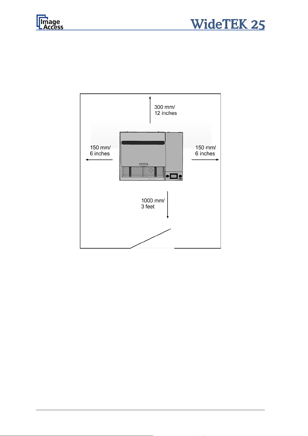
A.7 Device Location
Please allow a minimum of 150 mm (6 inches) from any side walls and 300 mm (12
inches) from a back wall. Leave one meter (3 feet) minimum distance from any door or
entrance way. Use the illustration below as a guide.
Picture 5: Minimum distances
Do not operate the scanner in an area that has poor air circulation and/or that is nonventilated.
Place the WideTEK 25 on a flat and solid base. The load bearing capacity of the base
must correspond to the device weight.
Placing the WideTEK 25 on the optional floor stand is recommended for the best
ergonomic position while using the scanner.
Choose a location that complies with the limits of temperature and humidity. Refer to the
technical specification.
Note: Before using the WideTEK 25 scanner in the new environment allow at least one
hour for temperature adaptation.
Temperature adaptation means:
A fast change from cold to warm environmental conditions can build up
condensation inside the housing. This will result in unfavorable scanned images
and could cause permanent damages to the unit.
Page 16 Setup and Assembly Manual
Page 17

A.8 Maintenance
Important: While cleaning the scanner, ensure that no liquids will penetrate into the
device housing.
A.8.1 Touchscreen
The touchscreen can be cleaned with a dry micro fiber cloth. Before cleaning the
touchscreen the WideTEK 25 must be switched off (see chapter A.11.2) and the main
power switch (see Picture 7, item 1) must be set to position 0.
A.8.2 Surfaces
Use a soft, dampened cloth to clean the housing of the scanner. Recommended is a micro
fiber cloth.
A.8.3 Glass plate
Important: Do not use any cleanser with solvents to clean the glass plate!
The glass plate of the WideTEK 25 has a special non-reflective surface coating.
Clean the glass plate with an appropriate glass cleaner and use a soft cloth.
Recommended is a micro fiber cloth.
After cleaning dry the glass plate with a soft cloth.
A.9 Repair
Note: There are not any parts of the WideTEK 25 scanner which can be repaired by
the user.
All repairs should be done only by a trained technician.
Setup and Assembly Manual Page 17
Page 18
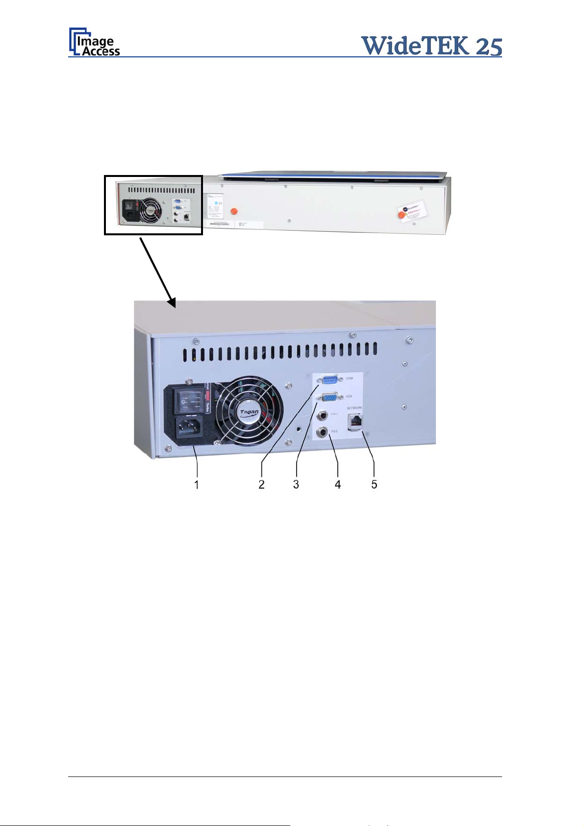
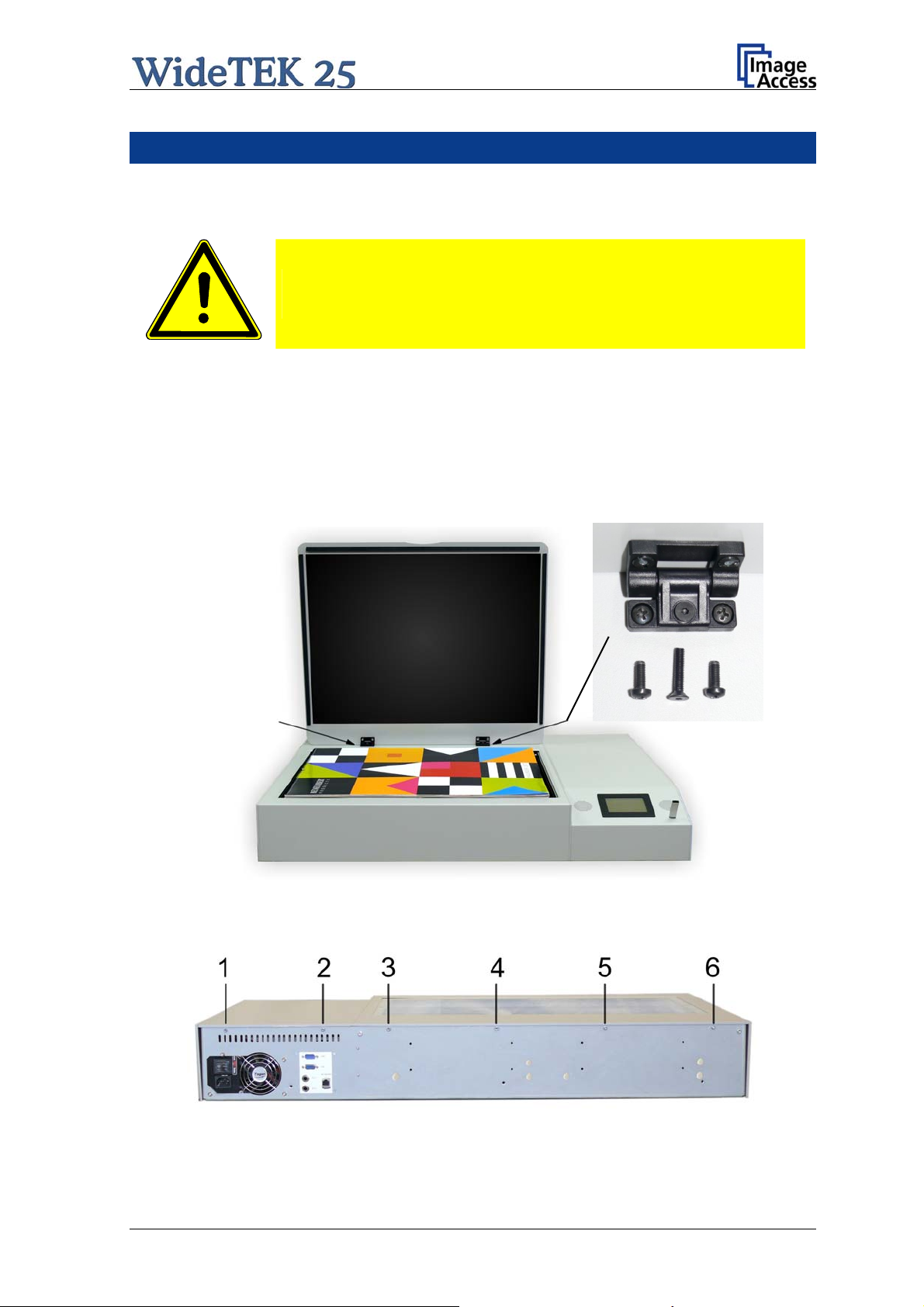
A.10 Connectors on the Back
All connectors are positioned at the right side of the back of the housing, seen from the
operator’s view (i.e. from the front of the scanner).
Picture 6: Back of WideTEK 25
Picture 7: Connectors on the WideTEK 25
1. Power connector and main power switch
2. Serial connector
3. VGA connector
4. Two foot pedal connectors
5. Network cable connector
Page 18 Setup and Assembly Manual
Page 19

A.10.1 Connecting to the Network
Insert the network cable (delivered with the scanner) into the network cable connector
(Picture 7, #5). Connect the other side of the cable to a plug-in of an existing network.
Alternatively the scanner can be connected dir
ectly to a computer with network card by
using the crossover cable. In this case ensure that the network addresses used by the
computer and the scanner allow direct connection.
A.10.2 Connecting to the Power Source
Before connecting the scanner to the electrical outlet check the following items:
Ensure the electrical outlet is in perfect condition and that it is
properly grounded.
Ensure that the electrical outlet is equipped with a fuse with the
proper capacity.
The electrical outlet must be near this device and must be easily
accessible.
Inspect the power cable and ensure that it is undamaged.
Use only the power cable delivered with the scanner.
Turn the device off before plugging or unplugging any cable.
Setup and Assembly Manual Page 19
Page 20

A.10.3 Powering up the WideTEK 25
The main power switch is found above the power connector. Picture 7 shows the position
of the power connector and main power switch.
Connect the power cable with the electrical outlet and switch the main power switch to
position I. When the main power switch is in position I, the scanner is in stand-by mode.
NOTE:
While using the WideTEK 25 in work conditions, it should
only be switched on and off by the touch panel!
A.11 WideTEK 25 Touch Panel
The WideTEK 25 parameters can be set and modified with the integrated touch panel. It
shows an easy-to-use menu and helps the user to control all scanner parameters with the
touch of a finger.
When the WideTEK 25 is powered up using the main power switch, the touch panel is
illuminated in a dimmed mode and shows the stand-by screen. The stand-by screen
shows the Image Access logo and the blinking message Touch screen to power up.
A.11.1 Starting the WideTEK 25 from Stand-By Mode
When the WideTEK 25 is in stand-by mode, it can be started by tapping the touch panel
on any arbitrary position. The touch panel lights up and a rotating hourglass indicates that
the start sequence is running.
When the start-up sequence is finished, the touch panel shows the start menu screen.
Picture 8: Start menu screen
Page 20 Setup and Assembly Manual
Page 21

A.11.2 Turning-off the WideTEK 25 by the Touch Panel
NOTE:
Always turn off the WideTEK 25 scanner with the Stop button on
the touch panel!
The main power switch should only be used before the scanner is
disconnected from the electrical outlet.
To turn off the WideTEK 25, press and hold the Stop button on the touch panel.
While the Stop button is held, a counter in the button shows the remaining time until the
WideTEK 25 is powered down.
Picture 9: Touch panel while shut down in progress
At the end of the power down sequence, the display will be dimmed.
Setup and Assembly Manual Page 21
Page 22

A.12 Network IP Address
Controlling the WideTEK 25 scanner is based on the Scan2Net technology.
That means, access to the scanner and to the integrated Scan2Net interface will occur by
using a network connection. Every browser software can be used to work with the
scanner.
The default network IP address of the scanner is 192.168.1.50
This IP address is also valid after using the function “Reset to Factory Defaults”.
To adapt the scanner to an existing network, the IP address and other network
parameters can be modified by using the touch panel as well as the Scan2Net interface.
The following chapter will describe how the IP address can be modified with the touch
panel. Another chapter, following later, will describe how to modify the IP address by
using the Scan2Net interface.
A.12.1 Adapting the IP address with the Touch Pa nel
When the WideTEK 25 is in stand-by mode, it can be started by tapping the touch panel
on any arbitrary position. The touch panel lights up and a rotating hourglass indicates that
the start sequence is running.
While the start sequence is running, tap on the touch panel at least three times
successively.
At the end of the start sequence the touch panel shows the menu Self Test 1.
Picture 10: Menu Self Test 1
By tapping the fields you can change to the submenus.
Page 22 Setup and Assembly Manual
Page 23

Tap on the field IP Address. The menu in the touch panel changes and shows the
Network setup mask.
Picture 11: Network parameters
Tap on the line to be changed, e.g. the Address line. The touch panel will show the
following:
Picture 12: Numerical keyboard
Enter the values with the displayed numerical key board. The keys < and > will move the
cursor, the key X deletes the character at the current cursor position.
After entering the IP address, tap on
the checkmark symbol finally.
The touch panel display then will change and shows the network parameters.
To save the modified values tap on the field Save.
The display changes again. Tap on Yes to confirm saving of the new values.
Picture 13: Confirm changes
After saving the changes the display returns to the Self Test 1 menu (Picture 10).
Setup and Assembly Manual Page 23
Page 24

A.13 Optical Adjustment
Whenever the device is setup for the first time, moved to a different location, cleaned or
serviced and/or after a software update; some adjustments have to be performed to
guarantee maximum quality and accuracy.
A.13.1 White Balance
The white balance function is the most important function for consistent image quality.
To ensure optimal performance, the WideTEK 25 should be calibrated in regular intervals
to compensate for light degradation, variations in the paper quality of the documents to be
scanned, and other long term effects;
A.13.1.1 Helpful information about the white balance adjustment
The scanner has built-in light sources of known and stable quality consisting of state-ofthe-art white LEDs.
In the first step, the overall sensitivity of the scanner is adjusted in such a way that the
brightest area results in an almost saturated output signal. This assures that the largest
density range possible is used. After this adjustment is done, the uneven light distribution
on the CCD caused by the imbalance of the lamps, the ambient light introduced, the
imperfections of the lens and other factors has to be compensated for.
This measurement results in a correction function which levels the brightness over the
complete scan width.
The quality of the test target is of utmost importance to the result of the white balance.
The test target is on reflective paper which diffuses the light. If the test target has dirt,
wrinkles or anything visible to the human eye on it, the CCD will also see this and will
overcompensate in these areas. Although the internal software has been programmed to
eliminate these imperfections to a certain degree, it still leads to unreliable results if the
target is not of the defined quality.
If the target is of defined quality, the scanner will calibrate successfully. Calibration means
that the “white” of the test target in the given illumination situation produces a “white”
output in the digital domain. Consequently, all scans of white paper having different
properties than the test target results in brightness and possibly color shifts.
Periodically performing the white balance adjustment is recommended to ensure
consistent best scan results.
Page 24 Setup and Assembly Manual
Page 25

A.13.1.2 Performing the White Balance Adjustment
Start the scanner as described in chapter A.11.1.
While the start sequence is running, tap on the touch panel at least three times
successively.
At the end of the start sequence the touch panel shows the menu Self Test 1 (Picture 10).
Tap on the field White Balance to activate the adjustment process.
< Back Returns to the former screen.
> Cont. Starts the measurement.
Abort Stops the measurement and the
display returns to the former
Picture 14: White Balance screen
screen.
Place the white balance test
target WT36-Z-02-A on the
upper margin of the glass
plate.
The test target must cover
the complete width of the
glass plate.
Now tap on > Cont.
Picture 15: Test target placed on scanner
Setup and Assembly Manual Page 25
Page 26

While the white balance adjustment is
running, the touch panel shows a
progress indicator.
Picture 16: Progress indicator
At the end of the measurement the
result will be displayed in the touch
panel.
Tap on the field Finish to return to
the menu Self Test 1.
Picture 17: White balance result
Page 26 Setup and Assembly Manual
Page 27

B Software Setup
Essentially, the scanner is a web server and comes with its own HTML-based user
interface. To access a Scan2Net scanner, any standard web browser can be utilized.
B.1 Start Screen of the Scan2Net User Interface
Start your browser.
Enter the IP address of the scanner. The default IP address of the scanner: 192.168.1.50
The start screen of the integrated user interface will be displayed.
Picture 18: Start screen
The start screen shows three symbols, which lead to the main categories of the Scan2Net
user interface.
Launch Scan Application changes to the main screen of the scanner interface.
Setup Device changes to the setup menu. Start ing with the following chapter, the basics
of the scanner configuration will be described.
Information shows a list of basic information about the scanner, e.g. serial number, the
firmware version, the IP address and many more.
Setup and Assembly Manual Page 27
Page 28
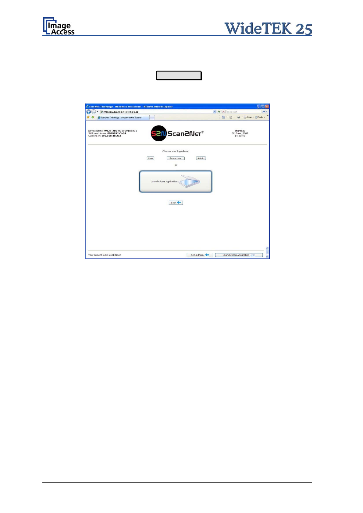
B.2 Setup Menu
Click in the start screen on the button Setup Device .
The next screen shows three buttons to select the login level. The access to the levels
Poweruser and Admin are password protected.
Picture 19: Login level screen
B.2.1 Selecting the Login Level
User This level allows the user to get some status information of the
WideTEK 25 scanner. This are e.g. the firmware version, the remaining
lamp operating time, system information, and many more. Furthermore it
allows to set a few basic parameters.
Poweruser Password protected level. Allows to set an extended range of system
parameters and to execute some adjustments.
Admin Password protected. Allows to set a wide range of system parameters and
to configure the scanner in detail.
Access to the Admin level is limited for trained technicians.
Page 28 Setup and Assembly Manual
Page 29

B.3 Poweruser Login Level
For the following setup steps choose the login level Poweruser .
Default user name and default password for this login level are "Poweruser".
Note: Please consider that both the user name and the password are case-sensitive and
that the first letter of both the user name and password are upper case.
Picture 20: Poweruser main menu
The person having access to this level can change the password and thereby limit access
to normal operators.
The main menu screen for the Poweruser level opens. The main menu is separated in
several sections.
The subsequently described settings broaden the functionality of the scanner or activate
additional functions.
Setup and Assembly Manual Page 29
Page 30

Please notice: The description of the User Settings can be found in the operation
manual, chapter The SetupScreen.
B.3.1 Setting the Network Parameters
Find the section Base Settings and click on the Network Configuration button.
Picture 21: Network parameters of the scanner
Now change the IP address, subnet mask and gateway to a valid address in your network
or select DHCP to obtain an IP address automatically.
After modifying the network parameters click on the Apply button to transfer the new
settings to the scanner. The scanner is now accessible with its new IP address.
Note: Depending on the used browser, it is necessary to delete the cache of the
browser before the scanner is accessible.
Enter the new IP address of the scanner and again open the Poweruser main menu as
previously described.
Page 30 Setup and Assembly Manual
Page 31

B.3.2 Adjust Time & Date
In the Poweruser main menu screen (Picture 20) locate the section Base Settings. Click
on the button Adjust Time & Date .
Picture 22: Adjust Time and Date Screen
Select the time format.
Enter in section NTP Server all parameters for the communication with a NTP server.
Select the time zone and the daylight saving function.
Manually set the time and the date.
Click the button Manually to refresh all above modified data.
Click the button via NTP to connect to the above defined NTP server.
Note: By default, the name of a scanned image contains the scan time and date,
therefore synchronizing the internal clock can be of some value.
Setup and Assembly Manual Page 31
Page 32

B.3.3 Sound Control
Locate the section Base Settings in the Poweruser main menu screen and click the
Sound System button.
Picture 23: Sound System screen
This menu allows to
set the volume,
upload additional sound files to the scanner,
link events to sound files.
Page 32 Setup and Assembly Manual
Page 33

B.3.3.1 Set Volume
Click on the button Set Volume .
Picture 24: Volume level displayed
To set the volume level, click on the desired percentage value in the list left beside the
graphic symbol.
The symbol color changes depending on the selected value.
Up to 30% Up to 60% 70% or higher
Back to Sound Menu returns to the former menu.
Back to Main Menu returns to Poweruser main menu (Picture 20).
Setup and Assembly Manual Page 33
Page 34
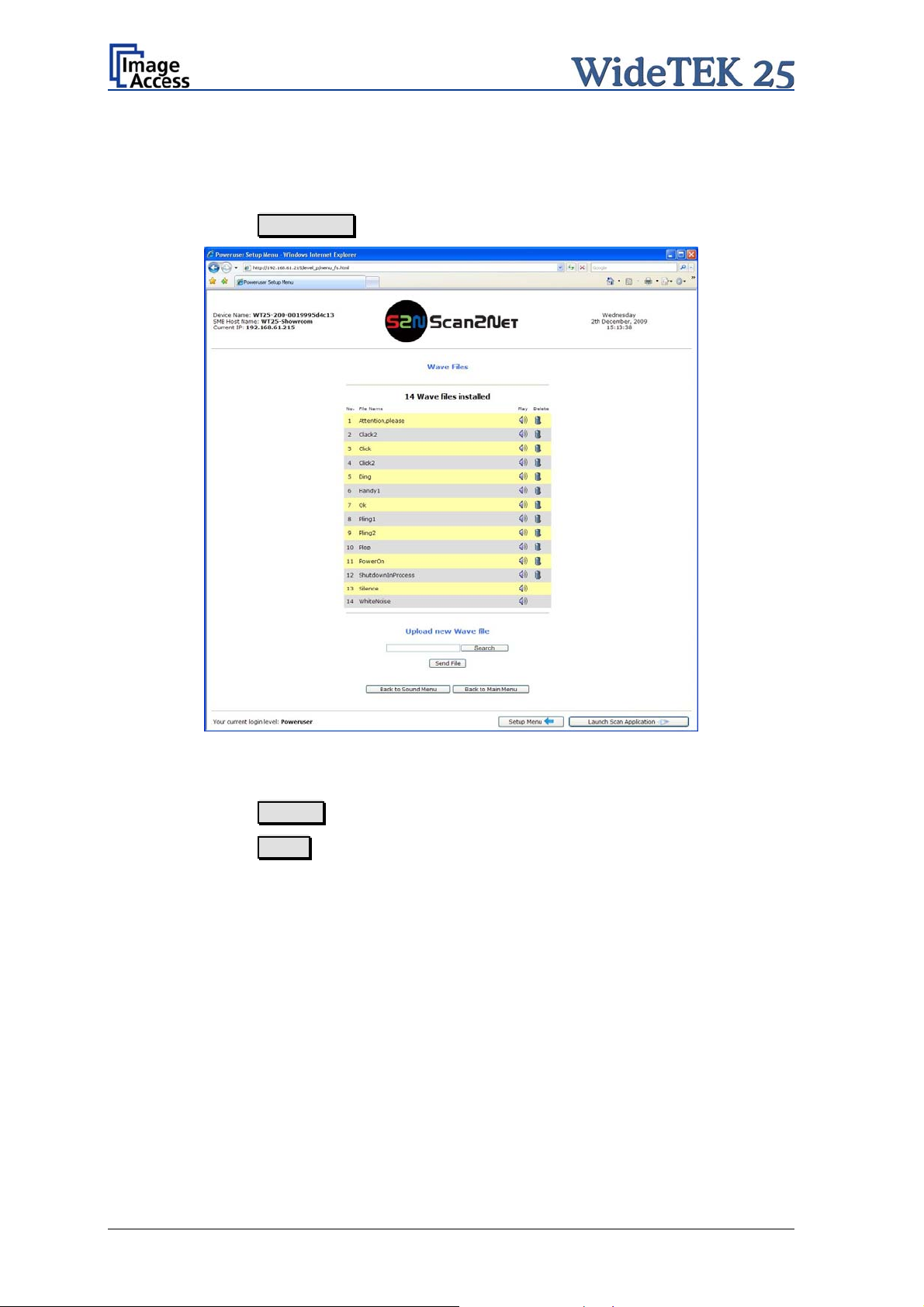
B.3.3.2 Wave Files
Additionally sound files can be uploaded to the already installed sound files. The data
format of the sound files is WAV.
Click on the button Wave Files .
Picture 25: List of sound files
The list of the installed sound files will be displayed.
Click on the button Search to search for the desired WAV sound files.
Click on the button Send to upload the files to the scanner.
Page 34 Setup and Assembly Manual
Page 35

B.3.3.3 Link Events
A sound can be assigned to various action items. This will be played every time the
condition occurs. The default setting can be overwritten.
Click on the button Link Events
Picture 26: Link Sounds to Events screen
The list shows the event and the sound name which is linked to it.
The sound that should replace the current sound can be selected in the next row. Click on
the selection arrow to open the list of available sounds.
The selected sound will be linked to the event by clicking the symbol.
Click on the button Apply to transfer the changes to the scanner.
Back to Sound Menu returns to the former menu.
Back to Main Menu returns to Poweruser main menu (Picture 20).
Setup and Assembly Manual Page 35
Page 36

B.3.4 Firmware Update
The Image Access Customer Service Portal at http://service.imageaccess.de offers
downloads of firmware updates for every Scan2Net scanner. As a registered user, login
with your personal login name and password.
Select Actions S2N Device Updates to download the current firmware version. Enter the
serial number of your scanner and the version number of the firmware installed on the
scanner.
Download the current firmware version to your local PC.
Start the scanner. Select Setup Device and go to the login level Poweruser .
In the main menu screen, locate the section Updates & Uploads and click the
Update Scanner Firmware button.
Browse your local PC and select the previously downloaded firmware update file.
Picture 27: Firmware Update
After the firmware update is complete the scanner must be rebooted to activate the new
firmware.
Select “Reboot” in the line Post update behavior to reboot automatically after the
updating the firmware.
Page 36 Setup and Assembly Manual
Page 37

Click the button Send File to update the scanner’s firmware.
Important: Do not switch off the scanner while executing the firmware update!
The update sequence can last a few minutes. When the update is running, no messages
will be displayed on the screen.
After the firmware is successfully updated, the screen displays a summary.
Picture 28: Summary of successful firmware update
The scanner reboots now with factory default settings.
Setup and Assembly Manual Page 37
Page 38

B.3.5 Install ICC Profiles
Find the section Updates & Uploads in the Poweruser main menu screen and go to
ICC Profiles .
Select either Scanner Profile or Printer Profiles .
Picture 29: Select ICC Profile
The ICC profiles data will be integrated into the image files. ICC profiles match the color
space between scanner and imaging software or the color space between scanner and
printer.
By using ICC profiles scanned images can be reproduced with correct adapted colors.
Page 38 Setup and Assembly Manual
Page 39

Browse for a new ICC profile and select it. It will replace the previous file.
Picture 30: Upload ICC Profile
Setup and Assembly Manual Page 39
Page 40

B.3.6 Install Option
In the main menu screen, locate the section Updates and Uploads and go to
Install Options . All option keys that are displayed in green are valid and installed. A new
key must be entered completely without blanks or spaces followed by the Apply button.
If it does not turn green, the key is invalid or does not belong to this specific scanner or
option.
Picture 31: Install Option screen
Note: Option keys are valid only for one option on a specific scanner denoted by its
serial number.
If a key is accidentally deleted it can always be obtained again at the Image
Access Customer Service portal http://service.imageaccess.de
without
additional costs.
Page 40 Setup and Assembly Manual
Page 41
C Maintenance, Tests and Troubleshooting
C.1 Separating Device Cover from Device Body
Disconnect the power cable before doing any maintenance to the
device.
At first remove the glass plate cover. Two hinges hold the glass plate cover at the device
cover.
Each hinge has three screws which hold it at the device cover. Use a Phillips screwdriver
to remove the two screws on the left and right position. Use an Allen head screw driver,
size 2.5 mm, to remove the screw in the middle position of each hinge.
Note: Use the countersunk Allen head screw only at the middle position of the hinges!
Picture 32: Arrows point on the hinges to be removed
In the next step remove six hexagon head screws at the back side of the device body.
Picture 33: Hexagon head screws to be removed
Setup and Assembly Manual Page 41
Page 42

After the six screws have been removed the device cover must be lifted and pulled a little
at the front side as shown in the picture below.
Picture 34: Lift and pull the device cover
The device cover has six alignment pins on its front side. For easy orientation the position
of the alignment pins are marked in the above picture by the six white crosses.
They are visible when looking from above through the glass plate.
Picture 35: Arrows mark three of six alignment pins
While pulling at the device cover, look through the glass plate and stop pulling when the
alignment pins are out of their boreholes.
Page 42 Setup and Assembly Manual
Page 43

Hold the device cover at the left and right side and lift it up in the arrow direction as shown
in the pictures below.
Picture 36: Lifting the device cover in arrow direction
Picture 37:Separating device cover from device body
Because of the limited cable length it is recommended to place the device cover on the
front part of the device body. A second person should hold the device cover for the
following steps.
Setup and Assembly Manual Page 43
Page 44

Disconnect the audio cable …
Picture 38: Disconnecting audio cable
… and the signal cable.
Picture 39: Disconnecting the signal cable
After both cables are disconnected place the device cover with the glass plate down onto
a flat and stable base.
Page 44 Setup and Assembly Manual
Page 45

C.2 Assembling the Device Cover to the Device Body
The device cover is assembled to the device body in reverse order as described in the
previous chapter C.1.
First connect the audio cable (Picture 38) and the signal cable (Picture 39) to the touch
panel board.
At next slide the device cover onto the device body. Stop shortly before the device cover
comes to the back edge of the device body.
Lift the device body at its back side a little …
Picture 40: Lifting the device cover
…and then slide it carefully into its end position.
Picture 41: Device cover in end position
Watch the alignment pins on the front side. They should slide only a little into their
boreholes.
Setup and Assembly Manual Page 45
Page 46

C.2.1 Assembling the Glass Plate Cover
The glass plate cover has two adjustable hinges. These hinges avoid an undamped
moving of the glass plate cover.
The middle screw allows to set the damping force of the hinge.
Position the hinges of the glass plate cover over the threaded holes. Assemble each hinge
by using two Phillips head screws in the left and right borehole.
Fasten the screws by hand. Do not use an electric tool!
At next insert the countersunk Allen head screws in the middle borehole. Use an Allen
head screw driver, size 2.5 mm, to fasten the screws.
Picture 42: Setting the damping force of the hinge
Fasten the Allen head screws with normal manual strength. Move the glass plate cover
slowly up and down while fastening the Allen head screws.
Intention of this is, that the glass plate cover should move easily, but damped.
Page 46 Setup and Assembly Manual
Page 47

C.3 Cleaning the WideTEK 25 Scanner
Although the WideTEK 25 scanner is constructed with the focus on a minimum of cleaning
requirement, it is needful to clean some parts after a period of using.
C.3.1 Cleaning the Outside of the Glass Plate
It is recommended to clean the outside of the glass plate periodically to ensure constant
good scan results.
To clean the glass plate, lift up the glass cover. Use the microfiber cloth which is delivered
with the WideTEK 25 scanner or a fluff-free cloth.
Note: Because of the coating of the glass plate always use only a few drops of a
mild cleaning fluid with the microfiber cloth.
Moisten the microfiber cloth, then apply a few drops of a mild cleaning fluid and clean the
glass plate without pressing the cloth on it .
Use a soft cotton cloth to dry the glass plate after cleaning.
C.3.2 Cleaning the Inside of the Glass Plate
The inside of the glass plate should be cleaned in larger time periods.
To clean the inside it is necessary to remove the device cover from the device body. See
chapter C.1 for a detailed description of the necessary steps.
To clean th
scanner or a fluff-free cloth.
Note: Because of the coating of the glass plate always use only a few drops of a
Moisten the microfiber cloth, then apply a few drops of a mild cleaning fluid and clean the
glass plate without pressing the cloth on it .
Use a soft cotton cloth to dry the glass plate after cleaning.
e glass plate use the microfiber cloth which is delivered with the WideTEK 25
mild cleaning fluid with the microfiber cloth.
Setup and Assembly Manual Page 47
Page 48

C.4 Scan Test Targets
With the help of this function, the user can scan either a CSTT target or an IT8 target. The
targets are used to analyze specific features of the scanner’s camera and internal
parameters.
Some CSTT test target are delivered with the scanner.
In the Poweruser main menu screen find the section Adjustments & Support. Select
here Scan Test Targets . Another screen opens.
Select here either Scan CSTT Test Target or Scan IT8 Test Target .
C.4.1 Scan CSTT Test Target
When Scan CSTT Test Target is selected, the next screen shows how to position the
target on the document table.
Note: Place the CSTT test target with the printed side on the glass plate.
The picture on the screen shows the target with the printed side up. This is only to help
identifying the test target.
Picture 43: Position of CSTT test target on the glass plate
The test targets will be scanned and the image will be saved to a directory which is
defined by the user. The saved image can be used for support purposes.
Page 48 Setup and Assembly Manual
Page 49

C.4.2 Scan IT8 Test Target
When Scan IT8 Test Target is selected, the next screen shows how to position the
target on the document table.
Note: Place the IT8 test target with the printed side on the glass plate.
The picture on the screen shows the target with the printed side up. This is only to help
identifying the test target.
Picture 44: Position of IT8 test target on the glass plate
The test target will be scanned and the image will be saved to a directory which is defined
by the user. The saved image can be used for support purposes.
Setup and Assembly Manual Page 49
Page 50
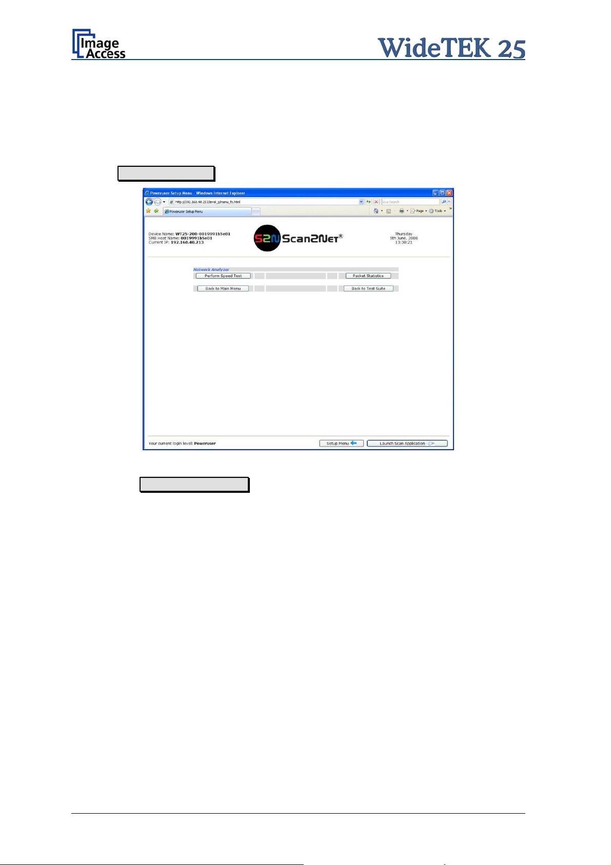
C.5 Network Analyzer
This function provides information about the data transfer speed of the network where the
Scan2Net scanner is installed.
Locate the section Adjustments & Support in the Poweruser main menu screen and
click the Network Analyzer button.
Picture 45: Network Analyzer screen
Click on the Perform Speed Test button and enter the IP address of the device which
should be the target for the test. Also enter the number of packets that should be sent for
testing.
Page 50 Setup and Assembly Manual
Page 51

Click the Perform Test button to start the test.
Picture 46: IP address for testing
The test results will be displayed in a diagram.
Picture 47: Network Analyzer test result
Setup and Assembly Manual Page 51
Page 52

C.6 Recovery Function
The recovery function helps to set all device parameters to factory defaults after a fatal
system breakdown.
The recovery key is necessary to invoke the recovery procedure.
A recovery key is delivered with every device,
it is marked
Picture 48: Recovery Key
Important: The recovery function resets the IP address to the factory default value of
192.168.1.50. It may be necessary to use the crossover cable and change
the network settings on the local computer.
with the label Recovery.
C.6.1 Important Notes Before Recovering to Factory Defaults
The steps described in the following should only be executed after a fatal system
breakdown!
Write down the values for the IP address, subnet mask and gateway of the device before
starting the recovery sequence.
After recovering to the factory default values, a firmware update has to be executed!
Make sure an update file is available on the local computer.
After recovering to the factory defaults, all adjustment procedures described in the
previous sections have to be executed again!
Page 52 Setup and Assembly Manual
Page 53

C.6.2 How to Recover to Factory Defaults
1. Power the device down with the stop button.
1. Power connector
and main power
switch
2. Serial
connector
3. VGA connector
4. Two foot pedal
connectors
5. Network cable
connector
Picture 49: Connectors on the WideTEK 25
2. Plug the recovery key into the serial connector (detail 2 in the above picture) at the
connectors panel.
3. Power the device up via the start button.
The device will start and, after it has found the recovery key to be present in the serial
port, it will automatically execute the recovery sequence. All viable system data will be
restored and necessary repair steps will be taken without the need of any user interaction.
Note: The recovery sequence can last some minutes. While the recovery sequence
is running, no message will be displayed.
4. When the recovery sequence has finished, the device will power down automatically.
Important: Do not switch off the device at any time during the recovery procedure!
5. Unplug the recovery key after the device has powered down.
6. Power up the device and launch the scan application in your browser.
The IP address of the device will have the factory default value: 192.168.1.50
Setup and Assembly Manual Page 53
Page 54

7. Change the network parameters to the values which were used before running the
recovery sequence.
Select Setup Device Poweruser . Locate the section S2N Base Settings and
click the button Network . Enter the values for IP address, subnet mask, and default
gateway.
Click the Apply button. Confirm the following message by clicking the OK button.
In the next screen, click the Reboot button.
Reconnect to the device using the new IP address.
8. Select Setup Device Poweruser . Locate the section Updates & Uploads and
click the button Update Firmware . Perform a firmware update.
9. After the firmware update, all software adjustments for the device must be performed.
Select Setup Device Poweruser . Locate the section Adjustments & Support
and click the button Adjustments . Perform the adjustments by clicking the
appropriate buttons.
Page 54 Setup and Assembly Manual
Page 55

C.7 Troubleshooting Matrix
Fields with a light blue background need the power user access level. All other fields are
available to all users.
Problem Possible cause Action
The touch screen does not
show the stand-by message.
Touching the touch screen
does not power up the
device.
Touching the STOP button
on the touch screen does
not power down the device.
Image is darker than
expected.
Image is brighter than
expected.
Image has horizontal stripes
or streaks.
No power Check main outlet, power cord, power-
on switch on the left side of the device.
Connector failure, software
glitch …
Internal software hangs,
application hangs …
The target used for white
balance is much brighter
than the scanning target.
The document is much
brighter than the target
used for white balance.
Improper white balance.
Switch power off for at least 10
seconds. Retry after touch screen is
illuminated again.
End all applications and retry. If
problem persists, touch the STOP
button for at least 10 seconds. Power
up again.
Go to the Adjustments function and
modify the Brightness Correction
setting.
Go to the Adjustments function and
modify the Brightness Correction
setting.
Exercise the White Balance
procedure.
Image shows a color shift
towards red (tint)
Image shows a color shift
towards blue (tint)
Image shows a color shift
towards red (tint)
The target used for white
balance is more blue than
the scanning target.
The target used for white
balance is more red than
the scanning target.
The scanner receives
significant amounts of
infrared light (sun or spot
lights) not visible to the
human eye.
Go to the RGB adjustments and lower
the gain on red.
Go to the RGB adjustments and lower
the gain on blue.
Change position, close blinds, dim or
shut off any bright spotlights.
Setup and Assembly Manual Page 55
Page 56

C.8 Error Codes and Warnings
The scanner does report error conditions on the display and through the API. Some errors
are only sent to the API.
A green problem description signals that operation of the scanner is still possible although
the error will have an influence on the behavior or quality of the scanner.
A problem description in red marks an errors which will stop the scanner and inhibits
further scanning.
C.8.1 Error Codes
Error # Error message shown in
the display
1 Scanner in use. An attempt to access the scanner
2 Invalid session ID. An attempt to access the scanner
4 Invalid password The stop button was pressed during
5 E05 S2N BOARD S2N board failure The S2N board is either not found or
7 USER BREAK Stop button pressed. The stop button was pressed during
8 User timeout The function ended because of a
9 Warming up The device is still warming up and
10 Invalid setting value. T he value sent to the device is
11 Setting does not exist. The settings does not exist.
12 Invalid user docsize. The size of the user format is invalid.
14 Invalid resolution or color
20 E20 MOTOR 1 (O)
SCAN DRIVE
21 Error 21 Motor 1:
Transport locked
Error message sent to
application
mode.
Motor 1 (Scan
switch permanently open.
Motor 1 / PCI 1 (Box driv
Transport locked
drive): End
Problem description
was made from a different
application.
with an invalid session ID was made.
the operation.
found defective. Make sure board is
sitting correctly on the motherboard.
the operation.
time out
cannot be used.
invalid.
Either the resolution or the color
mode is invalid.
The home position switch is
permanently open. The mechanics of
the corresponding motor could be
blocked or the switch/cable is
defective.
e):
Page 56 Setup and Assembly Manual
Page 57

Error codes, part 2
Error # Error message shown in
the display
30 File format not supported. The specified file format is not
31 Preview not possible The application specified an invalid
32 Invalid color conversion The application changed the color
33 No image available The application attempted to get an
55 E55 WRONG S2N HW
CCD PORTS
56 E56 WRONG S2N HW
REVISION NOT OK
56 Error 56: S2N Board: wrong
revision
60 Error 60: General camera
error
61 Error 61:
Camera 1 failed
62 Error 62:
Camera 2 failed
Error message sent to
application
rong S2N board detected
W
(not enough CCD ports)
rong S2N Board detected
W
(Revision not OK)
Wrong S2N Board detected
(Revision not OK)
General camera error.
Camera 1
Camera 2 failed.
failed Initializing of camera 1 failed. Check
Problem description
supported or it is invalid in
combination with the color mode.
preview scale. Not all scale factors
are allowed with all image sizes.
depth between scanning and image
transfer and a conversion between
these modes is not possible.
Example: scan in binary, then
changed color mode to truecolor.
image from the scanner and there
was no scan since the device was
turned on.
The S2N board found is not the right
one for this device. Error can occur
after a repair/exchange. Exchange
with correct board.
The S2N board found is not the right
one for this device. Error can occur
after a repair/exchange. Exchange
with correct board.
The S2N board found is not the right
one for this device. Error can occur
after a repair/exchange. Exchange
with correct board.
General error on the CCD camera
board. Check power, cables and
S2N-PCI board.
power, cables and S2N-PCI board.
Initializing of camera 2 failed. Check
power, cables and S2N-PCI board.
65 Error 65:
Camera 1 data bus error
66 Error 66:
Camera 2 data bus error
69 Error 69:
ADC error camera 1
Camera 1 data bus error. Test data transfer to camera failed.
Check cables / connectors to camera
1 and S2N-PCI board.
Camera
Camera 1 adc error. Test data transfer through analog
2 data bus error. Test data transfer to camera failed.
Check cables / connectors to camera
2 and S2N-PCI board.
digital converter failed. Check cables
/ connectors to camera 1.
Setup and Assembly Manual Page 57
Page 58

Error codes, part 3
Error # Error message shown in
the display
Error message sent to
application
Problem description
70 Error 70:
ADC error camera 2
75 General keyboard error General keyboard error. Check
80 E80 BAD LAMP CONFIG Bad lamp config
81 E81 BAD DEVICE CONFIG Bad device configuration
99 Internal error. The firmware has detected an
Camera 2 adc error.
Test data transfer through analog
digital converter failed. Check cables
/ connectors to camera 2.
keyboard and cables.
internal error of unknown cause.
C.8.2 Warnings
Warning # Warning shown in the
display
144 Light level is low
145 Camera adjustment required Camera adjustment required
160 W160 NO WHITE BALANCE
DATA
Warning sent to
Problem description
application
No white balance data No white balance data was found.
The light level is found to be low
during the white balance function.
Perform white balance.
C.8.3 Information
Info. # Information shown in the
display
200 CREATING
RECOVERY PART..
Information sent to
Description
application
Creating Recovery Partition While creating the recovery partition,
the scanner can not be accessed.
Page 58 Setup and Assembly Manual
Page 59

D Technical Data
D.1 Scanner Specifications
Optical System
Maximum Document Size 25 x 17,7 inch / 635 x 420 mm
Optical Resolution 1200 x 600 dpi
Sensor Type:
Two tricolor CCDs, e
proof
ncapsulated and dust-
Sensor Resolution: 45.600 pixels (2x 22.800)
Scan Modes:
Illumination:
Light Source: Two lamps with white LEDs
Warm-up Time: None
Temperature Dependence: None
UV / IR Emission None
Lifetime 50.000 hours scanning time
12bit grayscale (internal
36bit color (internal resolution)
1bit Black/W
8bit Grayscale
24bit Color,
hite
8bit indexed
resolution)
D.2 Ambient Conditions
Operating Temperature +5 to +40° Celsius
Storage Temperature 0 to +60 °Celsius
Relative Humidity 20 to 80% (non-condensing)
Noise Level 48 - 53 dB(A) (Operating)
33 dB(A) (Stand-by)
Setup and Assembly Manual Page 59
Page 60

D.3 Electrical Specifications
This device is Energy Star compliant.
Voltage 100–240V AC
Frequency 50/60 Hz
Power Consumption
Stand-by 0.1 W
Start Procedure 90 W
Ready to scan, lamps off 70 W
Scanning 105 W
D.4 Dimensions and Weight
Scanner outer dimensions 160 x 1026 x 782 mm (H x W x D)
6,3 x 40,3 x 30,8 inch
Weight of Scanner 41 kg
Weight of Transport Box 35 kg
Dimensions of fully packed Transport Box
Total shipping weight 76 kg
400 x 1200 x 960 mm (H x W x D)
15,75 x 47,25 x 37,8 inch
Page 60 Setup and Assembly Manual
Page 61

D.5 CE Declaration of Conformity
The undersigned, representing the manufacturer:
Image Access GmbH
Hatzfelder Strasse 161 – 163
42281 Wuppertal, German
herewith declares that the
Product: WideTEK 25 Scanner
Model Designation: WT25 –XXX
(XXX represents the device version number and configuration details)
Serial number: All
is in conformity with the following European standards and IEC directives:
EMC Directive 2004/108/EEC as per:
EN 55022:1998 + A1: 2000 + A2:2003
EN 61000-3-2:2000 + A2:2005
y
EN 61000-3-3:1995 + A1:2001
EN 55024:1998 + A1:2001 + A2:2003
FCC 47 CFR Ch.1 Part 15
Safety:
Low Voltage Directive (Safety) 2006/95/EEC as per
IEC 60950-1:2001
EN 60950-1:2001
UL 60950-1
CSA C22.2 No 60950-1-03
Wuppertal, 02.06.2008
Thomas Ingendoh , President and CEO
Setup and Assembly Manual Page 61
Page 62

D.6 FCC Declaration of Conformity
Responsible party:
Image Access GmbH
Hatzfelderstrasse 161 – 163
42281 Wuppertal, Germany
Product: WideTEK 25
Model Designation: WT25 –XXX
(XXX represents the device version number and configuration details)
For unique identification of the product configuration, ple ase submit the 12-digit serial number found on the
product to the manufacturer.
This device complies with Part 15, Class B of the FCC Rules. Operation of this
product is subject to the following two conditions: (1) This device may not cause
harmful interference, and (2) this device must accept any interference received,
including interference that may cause undesired operation.
Page 62 Setup and Assembly Manual
Page 63

For your notes
Setup and Assembly Manual Page 63
 Loading...