

Page 1

V1A-C35
Operation Manual
Page 2

File: ArbVers_BE4-V1A-C35_OperationManual_2015-KW45.docx
Art.-Nr.: BE4-V1-C35-MAN-EN
Page 3

Operation Manual Page 3
2015 by Image Access GmbH, Wuppertal, Germany.
Printed in Germany. All rights reserved.
Reproduction in whole or in part in any form or medium without express written permission of
Image Access is prohibited.
Scan2Net®, WideTEK® and Bookeye® are registered trademarks of Image Access.
All other trademarks are the property of their respective owners.
Image Access reserves the right to change the described products, the specifications or documents
at any time without prior notice.
For the most recent version, always check our web site www.imageaccess.de or
www.imageaccess.us or the customer service portal at portal.imageaccess.de
Page 4

Page 4 Operation Manual
Introduction
Dear Customer
We congratulate you on the acquisition of this innovative product from Image Access.
At Image Access, we are proud of the work we do; our products are the result of our
extremely high production standards and stringent quality control.
With the Bookeye® 4, Image Access offers an efficient V-cradle book scanner which covers
a wide range of applications due to its versatility. The integrated web based user interface
enables access to all functions via a structured set of menus.
This operation manual is designed to lead you through the most typical situations
experienced when operating the Bookeye® 4 scanner.
For this reason, we ask you to read the operation manual attentively before starting to work
with the device. By doing so, you will avoid operation errors and you can control all functions
effectively from the beginning.
In addition, please consider the following points:
• Damages to your unit may have occurred during shipping. Please check for
damages immediately after delivery of the unit. Inform your supplier if damage has
occurred.
• Read and ensure that you understand the safety notes. They were developed for
your protection and safety as well as to protect the unit.
• Regular maintenance conserves the high quality and safety of the Bookeye® 4
scanner during the entire service life.
If you have any further questions, please feel free to contact your local dealer or
Image Access, Inc. directly. Our staff will be happy to help you.
For your daily work with the Bookeye® 4, we wish you success and complete satisfaction.
Regards
Your Image Access Team
Page 5

Operation Manual Page 5
About this Manual
Operation Manual
The Operation Manual provides all necessary information pertaining to the normal
operation and behavior of the device. It is written for people who only operate the device
and do not perform setup and adjustment procedures. All device elements and software
functions are described in detail, although some of them might never be used. This manual
does not cover any application software. Refer to the appropriate manual to learn about the
application software.
All manuals can be downloaded from our customer service portal at portal.imageaccess.de.
Be sure to always check for the latest versions of these manuals.
This manual is divided into sections.
Section A Safety notes and device location. Read the safety notes attentively for your
own safety. Operate the scanner in a device location as described.
Section B Describes the hardware of the scanner and gives an overview of all
components and connectors. Remember that this device is a precise optical
instrument and should be handled accordingly.
Section C Hardware Operation. Describes how the hardware components may be
controlled.
Section C Contains all information about the User Setup Level
Section F Contains all technical information of the scanner .
Page 6

Page 6 Operation Manual
Version History
Version
Published in
Content/Changes/Supplements
A
January 2017
First version for Bookeye 4-V1A-C35 Rev. B
Page 7

Operation Manual Page 7
Table of Content
Introduction -------------------------------------------------------------------------- 4
About this Manual ----------------------------------------------------------------- 5
Version History --------------------------------------------------------------------- 6
A Safety Notes and Device Location ------------------------------------- 11
A.1 Safety Notes ............................................................................................. 11
A.1.1 Marking of Safety Notes 11
A.1.2 Laser Safety Note 11
A.2 Safety Precautions .................................................................................... 12
A.4 Maintenance ............................................................................................. 13
A.4.1 Touchscreen 13
A.4.2 Surfaces 13
A.4.3 Book Cradles 13
A.5 Repair ................................ ................................ ................................ ....... 13
A.6 Content on Delivery .................................................................................. 13
B Hardware ----------------------------------------------------------------------- 14
B.1 Device Overview ....................................................................................... 14
B.1.1 Front Side Elements 14
B.1.2 Connectors on the Rear Side 15
B.2 Connecting the Power Source .................................................................. 16
B.2.1 Starting the Bookeye® 4-V1A C35 17
B.2.2 Switching to Standby Mode 19
C Hardware Operation -------------------------------------------------------- 20
C.1 Book Cradles ............................................................................................ 20
C.2 Upper Touchscreen .................................................................................. 22
C.3 Lower Simatic Touchscreen ..................................................................... 23
C.4 Activating the Parameter Menu ................................................................ 24
C.4.1 Touchscreen Parameter Table 25
D Software Operation --------------------------------------------------------- 27
D.1 Lower Touchscreen Scan Modes ............................................................. 27
D.2 White Balance Adjustment ........................................................................ 28
D.3 The “Finger Removal” Function ................................................................ 31
D.3.1 Position of Document 31
D.3.2 Finger Positions 32
Page 8

Page 8 Operation Manual
D.3.3 Wrong Finger Positions 33
D.3.3.1 Distance too small 33
D.3.3.2 Finger position too steep 33
D.3.3.3 Fingers hold too close to the margin of the document 34
D.3.4 Examples of Finger Removal 35
D.3.4.1 Book positioned at the book cradle 35
D.3.4.2 Single finger holds the book 35
D.3.4.3 Multiple fingers hold the book 38
D.3.4.4 Small books with pattern at margin 40
E The Setup Level -------------------------------------------------------------- 41
E.1 Access Level User ................................................................................... 42
E.1.1 Device Info 43
E.1.2 Operation Info 44
E.1.3 User Settings 45
E.1.3.1 Language Selector 46
E.1.3.2 File Name 47
E.1.3.3 Power Saving 48
E.1.3.4 Volume 49
E.1.3.5 Foot Pedal 50
E.1.3.6 OCR 51
F Technical Data ---------------------------------------------------------------- 52
F.1 Scanner Specifications ............................................................................ 52
F.2 Electrical Specifications ........................................................................... 53
F.3 Dimensions and Weight ........................................................................... 53
F.4 Ambient Conditions .................................................................................. 53
Page 9

Operation Manual Page 9
Table of Pictures
Picture 1: Elements of the Bookeye 4-V1A C35 .............................................................. 14
Picture 2: Connectors on the rear side .............................................................................15
Picture 3 Control panel ....................................................................................................17
Picture 4 USB connectors and standby button .................................................................18
Picture 5: Book cradle in flat position; glass plate closed .................................................20
Picture 6: Book cradles in V position, glass plate open ....................................................21
Picture 7: Viewer & Job Control screen ............................................................................22
Picture 8: Start menu touchscreen ...................................................................................23
Picture 9: Content of parameter menu .............................................................................24
Picture 10: White calibration step 1 ..................................................................................28
Picture 11: White calibration step 2 ..................................................................................28
Picture 12: Symbol to activate the setup menu ................................................................29
Picture 13: Login window .................................................................................................29
Picture 14: Setup menu, white calibration ................................................................ ........30
Picture 15: White balance without glass plate ..................................................................30
Picture 16: Book at book cradle in flat position .................................................................31
Picture 17: Book at book cradle opened in “V” position ....................................................31
Picture 18: Correct finger position ....................................................................................32
Picture 19: Minimum vertical distance ..............................................................................32
Picture 20: Login screen ..................................................................................................41
Picture 21: User screen ...................................................................................................42
Picture 22: Device Info screen .........................................................................................43
Picture 23: Firmware information .....................................................................................43
Picture 24: Operation Info screen ....................................................................................44
Picture 25: User Settings start screen ..............................................................................45
Picture 26: Language Selector screen .............................................................................46
Picture 27: File name .......................................................................................................47
Picture 28: List of wildcard characters ..............................................................................47
Picture 29: Power Saving .................................................................................................48
Picture 30: Volume level ..................................................................................................49
Picture 31: Foot pedal settings .........................................................................................50
Picture 32: Functions for the foot pedal ............................................................................50
Picture 33: OCR information ............................................................................................51
Picture 34: Splitting start page .........................................................................................51
Page 10

Page 10 Operation Manual
Page 11

Operation Manual Page 11
A Safety Notes and Device Location
A.1 Safety Notes
Read and ensure that you understand the safety notes.
The safety notes have been written to ensure your protection and your safety.
Follow all safety notes to avoid damage to the device.
A.1.1 Marking of Safety Notes
All safety notes are marked with a warning sign.
A description of the potential hazard is found at the right side beside the warning sign.
WARNING!
<Text with description of potential hazard.>
A.1.2 Laser Safety Note
CAUTION!
Laser Class 1
Certified acc. IEC 60825-1:2008-05
Do not stare into beam!
LASER RADIATION
DO NOT STARE INTO THE BEAM OR VIEW
DIRECTLY WITH OPTICAL INSTRUMENTS
CLASS 2M LASER PRODUCT
Wavelength: 630-670nm
Max. Power: 5mW
≥ 7.5mrad
Certified acc. IEC 60825-1:2008-05
Page 12

Page 12 Operation Manual
A.2 Safety Precautions
Warning: Please read all the safety precautions before you operate the scanner. Serious
injury can occur to you or to others if you do not know how to use it safely.
To prevent fire or shock hazard, do not expose this device to rain or
any type of moisture.
Follow all safety precautions to avoid personal injury or damage to the device.
1. Openings in the scanner’s housing are provided for air circulation. Do not cover or block
the openings.
2. Do not place the scanner near a heat or cold emitting source such as a space heater,
furnace, or air conditioning unit.
3. Do not place the scanner near any devices or electrical boxes emitting high voltage.
4. Always place the scanner on a stable surface.
5. Do not place cups containing liquids or other such objects on the scanner or on the
book cradles. If liquid spills into the scanner it can cause damage. If this occurs, turn
the scanner off, unplug the power cord from the wall receptacle and contact the
Image Access Technical Support.
6. Do not put any objects into any scanner housing openings unless specifically instructed
to do so by Image Access Technical Support.
7. Do not disassemble the scanner. If there is a need to disassemble the scanner, please
contact the Image Access Technical Support.
8. Do not use the scanner if it has been physically damaged. If this occurs, turn the
scanner off, unplug the power cord from the wall receptacle and contact the
Image Access Technical Support.
9. The scanner should be used only with the power supply that is delivered with the
scanner. If you are unsure, please contact the Image Access Technical Support.
10. Image Access recommends plugging the scanner into an appropriately-rated power
conditioner.
11. Always turn the power off and unplug the power cord from the wall receptacle before
cleaning the scanner.
12. When cleaning, do not use any type of solutions, abrasives, or acids such as acetone,
benzene, kerosene, mineral spirits, ammonia, or nitric acid. Do not use any cleaners
that contain these chemicals.
13. Do not spray any liquids directly onto the scanner. Spray cleaning fluids directly onto
the cleaning cloth and use the cloth to clean the scanner.
Page 13

Operation Manual Page 13
A.4 Maintenance
Important: Ensure that no liquids penetrate into the device housing.
A.4.1 Touchscreen
The touchscreen can be cleaned with a micro fiber cloth.
Before cleaning the touchscreens of the dual display, switch the scanner unit power switch
(see item #5) to position 0.
A.4.2 Surfaces
Use a soft, dampened cloth to clean the housing of the scanner. Recommended is a
microfiber cloth.
A.4.3 Book Cradles
Important: The rubber mats on the book cradles may only be cleaned dry!
Use a vacuum cleaner from time to time to clean the mats from dust and particles.
A.5 Repair
Please note: There are not any parts or components of the Bookeye® 4 V1A-C35 scanner
which can be repaired by the user.
All repairs and service work should be done by a trained technician only.
A.6 Content on Delivery
The scanner is delivered in a wooden transport box. The transport box also contains:
• A reference folder with
- 4x CSTT-2 reference targets,
- 8x Line Reference Targets S2N-LRS-200.
• 3x White Reference Targets BE4-WA-V1-A.
• 1x Color Reference Set IT-8 folder
• A foot pedal switch
• Network cable, length 3 meters.
• A plastic bag with recovery key and instructions.
• A reference plate with reference label BE4-Z-C35-01-A.
• 3x power cables with connectors for European -, British- and US wall sockets.
Please note: Keep the wooden transport box for future use! If the scanner needs to be
returned to depot, it must be sent back in the original transport box to avoid
transport damages.
Page 14

Page 14 Operation Manual
B Hardware
B.1 Device Overview
B.1.1 Front Side Elements
Picture 1: Elements of the Bookeye 4-V1A C35
Some of the major components of the scanner have been identified in the above picture.
These components are referenced in this operation manual.
The main hardware elements are:
1. Camera head. The camera head contains the camera, the red line laser, and the lamps.
2. TFT flat screen. Shows the scanned image. All modifications of an image, e.g. color
mode or scan size, will be displayed immediately on the TFT flat screen.
3. Glass plate. Flattens the curvature of the book binding and ensures a continuous focus
level. The glass plate opens and closes motor-powered.
4. V-shaped book cradle. Can be fixed in “V” position or lie in a flat position. The opening
angle of the book cradle plates in V-position is 140 degrees.
5. Motor-powered lifting column.
6. Dual display to set the scan parameters (upper touchscreen) and to control the lifting
columns of the book cradle plates, the glass plate, and the automated scan modes
(lower touchscreen).
Page 15
Operation Manual Page 15
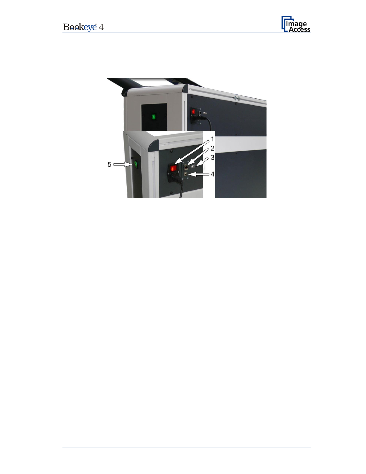
B.1.2 Connectors on the Rear Side
For easy orientation, the connectors found on the rear side of the scanner are depicted in
the following picture and described below.
Picture 2: Connectors on the rear side
1. Main power switch with integrated power cable connector
2. Network connector. Insert a network cable for access to the scanner via the integrated
Scan2Net® user interface.
3. Connector for recovery key.
4. Foot pedal connector.
5. Second main power switch.
Page 16

Page 16 Operation Manual
B.2 Connecting the Power Source
Before connecting the scanner to the external power source check the following items:
Ensure the electrical outlet is in perfect condition and that it is properly
grounded.
Ensure that the electrical outlet is equipped with a fuse with the proper
capacity.
The electrical outlet must be near this device and must be easily
accessible.
Inspect the power cable and ensure that it is undamaged.
Use only the power cable delivered with the scanner.
Turn the device off before plugging or unplugging any cable.
Set the main power switch to position 0
The connector for the power source cable, the main power switch and the power switch for
the scanner unit are located at the back side of the device.
Page 17

Operation Manual Page 17
B.2.1 Starting the Bookeye® 4-V1A C35
The Bookeye® 4-V1A C35 has two power switches, one at its rear side and one on the right
side (see Picture 2).
The main power switch turns on the power for the motor-powered lifting columns, the motorpowered glass plate and the TFT flat screen and the scanner unit.
The standby button in the front panel (Picture 4) is illuminated in red.
The lower touchscreen starts with a self test and shows some status messages.
The self test lasts approximately one minute.
At the end, the touchscreen shows the control menu with the buttons of the motor-powered
lifting columns, the motor-powered glass plate and the scan modes control buttons.
Picture 3 Control panel
Page 18

Page 18 Operation Manual
The red illumination of the standby button signals that the Bookeye® 4-V1A C35 scanner unit
is in standby mode.
Picture 4 USB connectors and standby button
Press the standby button to start the scanner unit.
The button illumination changes to blue.
The scanner starts with self test routines and verifies all system components.
Status messages will be displayed on the TFT flat screen and on the upper color
touchscreen of the dual display.
At the end of the startup sequence, the touchscreen displays the start screen.
Page 19

Operation Manual Page 19
B.2.2 Switching to Standby Mode
IMPORTANT: Always use the “Standby” button to switch the scanner to
standby mode.
Press and hold the standby button for at least three seconds. While pressing the button, a
“click” sound is audible.
During the shut down sequence, the TFT flat screen and the upper touchscreen of the dual
display show the scanner name and version and a progress bar.
The shut down sequence will take a few seconds.
Finally, the TFT flat screen and the touchscreen switch off.
The “Standby” button will be illuminated red.
The lower touchscreen remains on when the scan unit is in “Standby” mode.
Page 20

Page 20 Operation Manual
C Hardware Operation
The Bookeye® 4 V1A C35 scanner is equipped with two motor-powered lifting columns and
a motor-powered glass plate.
The integrated Scan2Net software as well as an external scan application allow the user to
scan a wide range of documents with brilliant quality and a high throughput.
The scanner settings can be defined by the upper touchscreen. It shows the menus of the
Scan2Net kiosk user interface.
The motor-powered glass plate, the motor-powered lifting columns and the scan modes can
be controlled by the user through the lower touchscreen with the Simatic interface..
The scanner can also be controlled by an external scan application.
The next chapters describe the functions of the two touchscreens and the available
automated scan modes.
C.1 Book Cradle
The book cradle can take up two different positions when the Bookeye® 4 V1A-C35 scanner
scans your documents.
Either flat position …
Picture 5: Book cradle in flat position; glass plate closed
Page 21

Operation Manual Page 21
… or V position.
Picture 6: Book cradles in V position, glass plate open
The V position is recommended for very delicate, old books and other documents that
cannot take up a flat position. The opening angle of the book cradle is 140 degrees.
IMPORTANT: Before setting the book cradle to V position, press INIT on the lower
Simatic touchscreen.
For setting the book cradle in V position, always select V-Scan from the
lower touchscreen menu.
When you lift the book cradle up to V position, a support at each side keeps the cradles in
position. The glass plate cannot move while the cradle is in V-position.
In both positions, the plates can also be shifted apart to enlarge the gap between them.
Adjust the gap to match the spine.
When changing the book cradle from V position to flat position, fold the supports to the
inside.
Page 22

Page 22 Operation Manual
C.2 Upper Touchscreen
The Scan2Net kiosk user interface is structured in four sections, which allow operators to
control and select various functions of the scanner.
Picture 7: Viewer & Job Control screen
The touchscreen is structured in four sections, which allow operators to control and select
various functions of the scanner.
1: This section shows a preview of the scanned image and in job mode, allows the
operator to scroll through the list of scanned images, delete images from the list and
to insert images into the list.
2: Buttons to open a menu with more settings. Touching the button again, closes the
menu and returns to the former screen.
3: This section is used to set the scanner’s default parameters, select the Job Mode
and to start the scan sequence.
4: This section displays information. It shows the selected user, gives status messages
and names the scanner type.
Page 23

Operation Manual Page 23
C.3 Simatic Touchscreen
The content displayed in the touchscreen varies depending on the selected scan mode.
If a function is not available in a specific scan mode, the control symbols greyed out.
Picture 8: Start menu touchscreen
The lower touchscreen enables the operator
1. to select one of three scan modes,
2. to move the book cradle plates up and down separately,
3. to initialize the book cradles and the glass plate,
4. to move the book cradle plates up and down simultaneously,
5. to open and close the glass plate,
6. to start and stop the scan sequence.
Page 24

Page 24 Operation Manual
C.4 Activating the Parameter Menu
Important! While the Admin mode is active, do not select the VSCAN (F2) scan
mode in the start menu.
The opening angle of the glass plate will override the defined
limit.
Severe damage to the glass plate can result.
To avoid damages, please do not change any parameters in the
parameter menu!
Press the button “F4” in the bottom line of the touchscreen to open the parameter menu.
Picture 9: Content of parameter menu
1. Parameter table. Detailed description in chapter C.4.1.
2. Controls to move the lifting columns and the glass plate up and down.
Lift1: Moves the left column up and down.
Lift2: Moves the right column up and down.
Lift3: Moves the glass plate up and down.
3. Lift1/2: Moves both lifting columns simultaneously up or down.
4. Buttons with predefined functions
Page 25

Operation Manual Page 25
CALIBRATE
The maximum lifting height of the lifting columns is limited by a light
barrier. The light barrier is positioned in the upper part of the bottom unit.
To place the calibration target in the correct position, it must be pressed
to the bottom side of the closed glass plate.
Touch CALIBRATE in order to oversteer the light barrier limit. Then lift
the lifting columns until the calibration target is pressed at the glass plate
bottom side.
INIT
Starts the initialization sequence.
Both lifting columns move down to the zero position.
The glass plate closes, i.e. it moves downward completely. Subsequently
it opens to its “INIT” position.
Then both lifting columns will be lifted to their “INIT” position.
ESC
Closes the parameter menu and returns to the start screen.
TIME SCAN
Defines the time the book cradle and glass plate controller will wait for a
scan command from the scanner. After the time has passed, the
controller moves the book cradles and opens the glass plate.
C.4.1 Touchscreen Parameter Table
The parameter table allows the operator to set value for the initialization and shows status
information.
The first column names the controlled elements.
L1: Lifting column motor left
L2: Lifting column motor right
L3: Glass plate motor left
L4: Glass plate motor right
UP L1
UP L2
Values from 1 … 100
Defines the speed when moving the lifting columns L1 and L2
upwards.
UP L3:
UP L4:
Defines the motor’s speed when the glass plate opens.
DOWN L1
DOWN L2
Values from 1 … 100
Defines the speed when moving the lifting columns L1 and L2
downwards.
DOWN L3:
DOWN L4:
Defines the motor’s speed when the glass plate closes.
Page 26

Page 26 Operation Manual
SLOW L1:
SLOW L2:
Defines the speed when moving the lifting columns L1 and L2
up-/downwards while the light barrier detects them.
POS L1
POS L2
Shows the height of the lifting columns, measured from the
zero point
POS L3
Shows the opening height of the glass plate, measured from
the fully closed position.
INIT L1
INIT L2
Values from 10… 300
Defines the height from the zero point for the lifting columns
after initialization.
INIT L3
Values from 1 … 999
Defines the opening height of the glass plate after a scan
sequence, when scanning in regular mode.
WEIGHT L1
WEIGHT L2
Shows the weight measured by the push button switches of
the left (L1) and right (L2) book cradle plate.
Maximum load: 45 kg / 99 lbs.
If the maximum load is overridden, the motor of the respective
lifting column will stop automatically. A red signal lights up on
the touchscreen.
OFFSET L1
OFFSET L2
Allows setting an offset for the maximum load which will be
lifted.
Note: Increase the offset value in small steps and check
the lifting columns for proper function.
There is a risk of destroying the glass plate if the
offset value is too high.
Min: 5 ≈ 10 kg / 22 lbs.
Max: 30 ≈ 30 kg / 66 lbs.
Increasing the offset value is recommended when documents
with heavy weights will be scanned.
V Scan L1
V Scan L2
Only if the book cradle plates are set in V-position!
Defines the height from the zero point for the lifting columns
when VSCAN mode is selected.
V Scan L3
Only if the book cradle plates are set in V-position!
Defines the opening height of the glass plate when VSCAN
mode is selected.
The glass plate will be opened in VSCAN mode automatically
to the defined height.
Page 27

Operation Manual Page 27
D Software Operation
D.1 Lower Touchscreen Scan Modes
The Bookeye® 4 V1A C35 scanner offers three automated scan modes. They can be
selected by the three buttons in the bottom row.
BOOKSCAN
The opened glass plate will be closed automatically before the scan
sequence starts.
The plates will be lifted until the document is pressed with a defined force
on the glass plate’s bottom side.
The scan will be executed.
The book cradle plates will return to the height of their start position.
REGULAR
This is the most comfortable mode.
The opened glass plate closes automatically before the scan sequence
starts.
The book cradle plates will be lifted until the document is pressed with a
defined force on the glass plate’s bottom side.
The scan will be executed.
The book cradle plates return to the height of their start position.
The glass plate opens until a pre-defined position is reached.
V-SCAN
Recommended for delicate documents, for example historic books.
Set the book cradle plates to V position. A support on each side keeps
the plates in this position.
Lift the book cradle plates so that the middle height of the document has
approximately the same height than the glass plate when it is in closed
position.
The scan will be executed.
The book cradle plates stay at their position.
The glass plate stays open.
Important! Before changing or choosing any mode on the cradle controller, please
perform a INIT!
Page 28

Page 28 Operation Manual
D.2 White Balance Adjustment
1. First, press the “INIT” button on the lower Simatic touchscreen to initialize the book
cradle and the glass plate. See picture 8, arrow number. 3.
2. Choose the book mode on the Simatic touchscreen. See Picture 8, arrow 1.
3. Put the calibration plate on the book cradle as shown on the following picture, with
the white calibration target on it.
Picture 10: White calibration step 1
4. Press the F4 button on the Simatic touchscreen to access the parameter menu.
5. Press the calibration button, the calibration mode will then be enabled for 5 minutes.
See Picture 8 arrow 4.
6. Lift left and right half of the book cradle simultaneously to the maximum height by
pressing the arrow up button “Lift 1-2”.
Picture 11: White calibration step 2
Page 29

Operation Manual Page 29
7. Activate the Setup Menu on the Scan2Net touchscreen
To activate the setup menu, tap the gear icon in the upper-right corner of the
touchscreen (see red circle).
Picture 12: Symbol to activate the setup menu
On the next screen, enter user login and password.
The default user login is Poweruser, the default password is Poweruser as well. Please
note that both user login and password are case-sensitive.
Picture 13: Login window
After entering the user login and the password, tap Ok to confirm.
Page 30

Page 30 Operation Manual
The screen content changes and shows the setup menu for white calibration.
Perform the white calibration with the glass plate closed by using the “Calibrate GP button”.
Picture 14: Setup menu, white calibration
8. Move the glass plate upwards with the “Lift 3” upper arrow button. While pressing
on the arrow up button, a login mask will be shown. It is necessary to login as Admin.
(user = admin password= scan2net) The glass plate opening angle should be in Vmode.
Picture 15: White balance without glass plate
Warning: The glass plate opening angle is not limited! The glass plate can crack if it hits the
neck of the device.
9. Perform the white balance without glass plate with the “Calibrate” button
Page 31

Operation Manual Page 31
D.3 The “Finger Removal” Function
D.3.1 Position of Document
The Bookeye® 4 scanner offers a helpful function which detects fingers at the margin of
books and eliminates them from the image. This is the “Finger Removal” function.
The following simple steps must be completed to operate the scanner using the “Finger
Removal” function properly:
• The book cradle can be set to either “V” position or flat position.
• Place the book as shown in Picture 16 on the book cradle.
Picture 16: Book at book cradle in flat position
Allow a small distance between the book’s bottom side and the lower margin of the book
cradle.
Picture 17: Book at book cradle opened in “V” position
• The distance depends on the thickness of the book. The distance should be at least
half of the thickness of the book.
• Align the book parallel to the horizontal red laser line.
• Position the book binding at the lowest point of the book cradles, opened in "V"
position.
Page 32

Page 32 Operation Manual
D.3.2 Finger Positions
Another important criteria for a proper function of the “Finger Removal” function is the
position of the fingers when holding the book in a flat position.
• The fingers must be positioned in a vertical area of max 1 inch = 25 mm width
measured from the book fan at each side of the book.
Picture 18: Correct finger position
Picture 18 shows the vertical area marked with blue lines at the left side and the right side
of the book.
The book fan area on each side is also marked.
• The fingers must be positioned with a distance of at least a third of the book side
length from the upper left corner of the book.
Picture 19: Minimum vertical distance
Holding the book at both sides with one or more fingers is also possible if the above
described criteria are kept.
Page 33

Operation Manual Page 33
D.3.3 Wrong Finger Positions
Some finger positions can cause malfunction of the “Finger Removal” function.
The following chapters show a few examples of wrong and correct finger positions.
D.3.3.1 Distance too small
The fingers should be positioned with distance to the text or to graphical elements in the
document.
If the distance is too small, the “Finger Removal” function may not remove the fingers from
the image or the element (e.g. part of the text) will be removed together with the fingers.
Wrong
Correct
Increase the distance between finger and text or picture.
D.3.3.2 Finger position too steep
When the book cradle plates are set to “V” position, the lamps may generate shadows
around the fingers if they held too steep.
Wrong
Correct
Always place the fingers flat on the edge of the document.
Page 34

Page 34 Operation Manual
D.3.3.3 Fingers held too close to the margin of the document
When the fingers are held too close to the document’s margin, they will not be removed by
the “Finger Removal” function.
Wrong
Correct
Move the fingers in small steps from the edge of the document to the inside and repeat the
scan sequence.
Page 35

Operation Manual Page 35
D.3.4 Examples of Finger Removal
Some examples in the following chapter show the functionality of the “Finger Removal”
function. Finger Removal is available in all document modes
A requirement is that the scanner is set to Book Mode in the ScanWizard application or the
external software.
D.3.4.1 Book positioned at the book cradle
Book Mode, Finger Removal Mode: Book Fan
Book position
Scan result
The setting „Finger Removal Mode: Book Fan“ cuts away the left and right book fan from
the resulting image and flattens the curvature of the book binding.
D.3.4.2 Single finger holds the book
Book Mode, Finger Removal Mode: On, Finger Removal Color: Auto
Note: The Finger Removal Color is defined in the ScanWizard user interface.
Book and finger position
Scan result
This setting corrects the resulting image as with the previous setting.
Additionally, the finger contour will be detected. It is eliminated in the image and the finger
contour area is filled with a pattern and/or color.
The filling color is automatically taken from the area above and below the finger contour.
Page 36

Page 36 Operation Manual
Book Mode, Finger Removal Mode: On, Finger Removal Color: Black
Note: The Finger Removal Color is defined in the ScanWizard user interface.
Book and finger position
Scan result
The resulting image now shows the area where the finger contour was detected. The
detected area is filled with a solid black color.
Small book kept flat by single finger
Book Mode, Finger Removal Mode: On, Finger Removal Color: Black
Note: The Finger Removal Color is defined in the ScanWizard user interface.
The “Finger Removal” mode works properly with books of different dimensions.
Book and finger position
Scan result
For demonstration purposes, the scan result shows the detected finger contour filled with a
solid black color.
Book position on the book cradle:
Page 37

Operation Manual Page 37
Large book (e.g. catalogue) kept flat by single finger
Book Mode, Finger Removal Mode: On, Finger Removal Color: Auto
Note: The Finger Removal Color is defined in the ScanWizard user interface.
Book and finger position
Scan result
The book fan has been removed and the surrounding black area is reduced to a minimum.
The scan result shows a part of the finger in the lower left corner.
The reason is that the analyzing algorithm detected an area of mixed patterns and colors at
the left border of the image. In this case, it is the register of the catalogue.
The finger at the lower left edge was interpreted as part of the register. For this reason, the
finger removal was not executed.
Page 38

Page 38 Operation Manual
D.3.4.3 Multiple fingers hold the book
Book Mode, Finger Removal Mode: Book Fan
Book and multiple fingers position
Scan result
Small book kept flat by multiple fingers
Book Mode, Finger Removal Mode: On, Finger Removal Color: Auto
Note: The Finger Removal Color is defined in the ScanWizard user interface.
If parts of the content of the book are covered by a finger or by multiple fingers, the removal
function detects the contour and fills the area with the selected fill option.
Book and multiple fingers position
Scan result
The white arrows in the scan result image mark the area where the finger contours have
been filled with automatically defined color.
Page 39

Operation Manual Page 39
Book Mode, Finger Removal Mode: On, Finger Removal Color: Auto
Note: The Finger Removal Color is defined in the ScanWizard user interface.
Book and multiple fingers position
Scan result
The position of the three fingers has been detected.
The fingers contour is eliminated in the resulting image and filled with a pattern and/or color.
If Finger Removal Color is set to Auto the filling color and/or pattern is automatically taken
from the area above and below the finger contour.
When the detected finger contour is filled with solid black, the result looks like this:
Page 40

Page 40 Operation Manual
D.3.4.4 Small books with pattern at margin
If a book has small dimensions, the finger removal mode Book Fan very often delivers good
results without flattening the book by fingers.
Book Mode, Finger Removal Mode: Book Fan
Book position
Scan result
The scan result shows the content of both pages. The curvature of the book binding is
flattened and the pattern at the margins has been removed.
Position of the book on the book cradle:
Page 41

Operation Manual Page 41
E The Setup Level
The setup level is divided into three access levels. The access levels Poweruser and
Admin are password protected.
The User access level allows showing certain information about the system such as power
up time, remaining lamp life time or firmware version.
Furthermore, the access level User allows setting some basic parameters.
Start your browser and enter the IP address of the scanner to get access to the scanner.
The Scan2Net® main menu (see Fehler! Verweisquelle konnte nicht gefunden werden.)
will open.
The Login Screen
On the start screen, click the button Setup Device .
The next screen shows the login levels User , Poweruser and Admin .
Picture 20: Login screen
Please note: The login levels Poweruser and Admin are password protected. Only
trained technicians should use these levels.
Page 42

Page 42 Operation Manual
E.1 Access Level User
Click the button User . This will open the below displayed screen.
Picture 21: User screen
The user screen is divided into two sections.
The section Device Information shows some details of the scanner and gives general
operation information.
The section User Settings allows the user to define some basic parameters of the scanner.
The button System Shutdown switches the scanner off.
Page 43

Operation Manual Page 43
E.1.1 Device Info
In the section Device Information, click the button Device Info and the following list
(Fehler! Verweisquelle konnte nicht gefunden werden.) will be displayed.
Click the buttons below the headline Device Info to get specific scanner information.
Picture 22: Device Info screen
The tables following the keyword show the current status of the Bookeye® 4 scanner.
The most important information for users is the firmware version in the second table.
Picture 23: Firmware information
Other information may be of interest if a service technician is onsite or if the service hotline
is called.
To return to the USER screen, scroll down completely and click
the Back to Main Menu button.
To return to the Login screen, click the button
Setup Menu
Click the button Launch Scan Application to switch directly to the main screen of the
integrated ScanWizard user interface.
Page 44

Page 44 Operation Manual
E.1.2 Operation Info
In the section Device Information, click the button Operation Info and the following list
will show various scan counters and elapsed times.
Picture 24: Operation Info screen
The following table provides a brief description of the operation information.
Field
Description
Scan Count
The total number of scans performed since the scanner left
the factory. Each CCD scan cycle is counted, regardless of
it being a pre-scan or a full scan.
Power Up Cycles
The total number of power up cycles performed since the
scanner left the factory. Only the power up cycles are
counted which were invoked by the on/off button.
Job count
The total number of job mode activations for scanning.
Operating Time
The total operating time since the scanner left the factory.
This is the power on time only, standby time does not count.
Lamp Operating Time
The total lamp operating time since the scanner left the
factory.
Remaining Lamp Operating
Time
The typical remaining lifetime of the lamps. With normal
working conditions, the lamp life is sufficient for the lifetime
of the device.
To return to the USER screen, click the button Back to Main Menu or click on the “Return”
button in your browser.
To return to the Login screen click the button
Setup Menu
Click the button Launch Scan Application to switch directly to the main screen of the
integrated ScanWizard user interface.
Page 45

Operation Manual Page 45
E.1.3 User Settings
In the section User Settings, click the button User Settings and the following screen will
be displayed.
Picture 25: User Settings start screen
The Power Saving screen will be displayed as start screen of the User Settings section.
Click the links below the headline to set the respective parameters.
To return to the Login screen click the button
Setup Menu
To return to the USER screen (click the button Back to Main Menu .
Click the button Launch Scan Application to switch directly to the main screen of the
integrated ScanWizard user interface.
Page 46

Page 46 Operation Manual
E.1.3.1 Language Selector
Use the function Language Selector to set the language for the user interface and the OCR
language of the Bookeye® 4 scanner.
Picture 26: Language Selector screen
Click on the selection arrow beside Language and a list of available languages opens.
Select the desired language for the user interface with a mouse click.
The setting changes immediately after the selection.
Click the button Back to Main Menu to return to the USER screen respectively the button
titled in the selected language.
Page 47

Operation Manual Page 47
E.1.3.2 File Name
Use the function File Name to define a default file name.
Picture 27: File name
When defining the default file name, variables can be used. To see a list of the variables,
click the link Wildcard characters.
Picture 28: List of wildcard characters
Below the field “File Name”, the defined file name is displayed. To show the file name with
the defined variables, reload the page.
Page 48

Page 48 Operation Manual
E.1.3.3 Power Saving
Click the button Power Saving to set the timers for the standby modes and the standby
method. The available settings are displayed on the screen.
Picture 29: Power Saving
Click on the selection arrow to open the list of available values for the respective standby
mode. The list of available values varies with the selected standby mode.
Standby mode
Available values
Device standby after
Display standby after
Screen Saver after
Laser standby after
Standby Method
The selection “Never” disables the power save function of the respective menu item.
To return to the previous screen click the button Back to Main Menu .
Page 49

Operation Manual Page 49
E.1.3.4 Volume
Click the button Volume to set the loudspeaker’s volume of the scanner.
Picture 30: Volume level
A screen opens and shows a graphic to symbolize the volume level.
Click on the scale to set the volume level or right click with the mouse at the arrow and
move the arrow to the desired value while holding the mouse button pressed.
To return to the Login screen click the button
Setup Menu
To return to the USER screen click the button Back to Main Menu .
Click the button Launch Scan Application to switch directly to the main screen of the
integrated ScanWizard user interface.
Page 50

Page 50 Operation Manual
E.1.3.5 Foot Pedal
Click the button Foot Pedal to define a function for the foot pedals.
Picture 31: Foot pedal settings
The scanner has connectors on its rear side to connect a foot pedal. The symbol for the
second foot pedal will be used in a later firmware version.
Click below the symbol of Pedal FS-1 or Pedal FS-2 and select from the drop-down list
which action should be executed when the pedal is operated.
Picture 32: Functions for the foot pedal
Drop-down list item
Function
Start scan
Starts the scan with the selected scan area size.
Start scan left page
Starts the scan and displays the left page of the
selected scan area size.
Start scan right page
Starts the scan and displays the right page of the
selected scan area size.
Page 51

Operation Manual Page 51
E.1.3.6 OCR
Click the button OCR in order to select the OCR engine from the list.
If there is no OCR engine available, the screen displays a message that no OCR engine
has been found.
If no OCR engine is installed, the screen displays a message that no engine is installed.
Picture 33: OCR information
Picture 34: Splitting start page
To return to the Login screen click the button
Setup Menu
To return to the USER screen click the button Back to Main Menu .
Click the button Launch Scan Application to switch directly to the main screen of the
integrated S2N user interface.
Page 52

Page 52 Operation Manual
F Technical Data
F.1 Scanner Specifications
Scan Area / Document Size
Maximum scan area
635 x 850 mm (25 x 33.5 inch)
Scanner resolution
600 x 600 dpi
Optical resolution
600 x 400 dpi
Minimum document size
100 x 100 mm / 4 x 4 inch
Illumination
Light intensity while scanning:
Max. 1800 LUX
Standby, idle
0 LUX (lamps off)
Lamps
Light source
High Power White LED,
classified according IEC 60825-1: Class 1
Warm up time
None. Maximum brightness immediately.
Temperature related alteration
None
IR/UV radiation
None
Lifetime
50,000 hours (typ.)
Color modes
Grayscale digitization
24 bit
Color digitization
48 bit
Scan modes
36 bit color, 24 bit grayscale,
bitonal, enhanced halftone
Page 53

Operation Manual Page 53
F.2 Electrical Specifications
Connection
Voltage
100 – 240 V AC
Frequency
50/60 Hz
Power Consumption
Standby
25 W
Ready to scan, monitor on
110 W
Scanning
150 W
Fully automatic scan cycle
≤ 330 W
F.3 Dimensions and Weight
Scanner dimensions
1700 x 1100 x 960 mm (H x W x D)
67 x 43.3 x 37.8 inch
Total weight of scanner, ready to use
Approx. 140 kg / 309 lbs.
F.4 Ambient Conditions
Operating Temperature
5 to 40 °C / 40 to 105 °F
Storage Temperature
0 to 60 °C / 32 to 140 °F
Relative Humidity
20 to 80% (non-condensing)
Ambient luminance
≤ 300 Lux
Noise Level
< 55 dB(A) (Fully automatic scan cycle)
< 38 dB(A) (Scanning)
< 33 dB(A) (Standby)
 Loading...