

Page 1
Color
Operation Manual
This device is compliant.
Page 2

For your notes
File: IAC_BE2-Color-N2.doc
Page 3

Version history:
Version Published in Content/Changes/Supplements
A March 2002 Preliminary version.
Description of the device.
Description of the integrated user interface, Vers.2.
B April 2002 Additional information concerning user interface, Vers.2.x
C May 2003 User interface complemented and revised. User defined
formats by Java
D July 2005 Some minor changes in the S2N user interface. Some
menu item has been deleted or moved. Additional
information concerning firmware update procedure.
E September 2005 New content in chapter 13, Updating Firmware.
F January 2007 Firmware 4.8x: Some modifications in S2N user interface.
Content in some menus have been changed, help function
available by clicking a “question mark” in the upper right
corner of the S2N screen.
Printed in Germany. All rights reserved.
Reproduction in whole or in part in any form or medium without express written permission of
Image Access is prohibited. Scan2Net™ and other designated brands herein are trademarks of
Image Access.All other trademarks are the property of their respective owners.
Image Access reserves the right to change the described products, the specifications or
documents at every time without prior notice. For the most recent version, always check our
web site
www.imageaccess.de or the customer service portal at http://service.imageaccess.de
© 2002 – 2007 by Image Access, Inc.
534 NW 77th Street
Boca Raton, FL. USA 33487
Operation Manual Page 3
Page 4

Table of contents
1
Introduction---------------------------------------------------------- 9
2 Safety Notes --------------------------------------------------------10
2.1 Marking of Safety Notes........................................................................... 10
2.2 Connecting to the Power Source ............................................................. 10
2.3 Device Location ....................................................................................... 11
2.4 Replacing Lamps ..................................................................................... 11
2.5 Maintenance and Repair.......................................................................... 11
2.6 Cleaning................................................................................................... 11
3 Device Overview --------------------------------------------------12
4 Content on Delivery ----------------------------------------------13
5 Establishing Connections ------------------------------------- 14
5.1 Main Power.............................................................................................. 14
5.2 Connecting the Network Cable ................................................................ 14
5.3 Connecting a Foot Pedal Switch .............................................................. 15
5.4 Possible Disturbance at Power Up........................................................... 15
6 Operation ------------------------------------------------------------16
6.1 Starting the BOOKEYE Color .................................................................. 16
6.2 Switching off the BOOKEYE Color........................................................... 17
6.2.1 Special Case: Switching off by STOP Key Not Possible 17
7 Keyboard ------------------------------------------------------------18
7.1 FORMAT.................................................................................................. 19
7.2 TYPE ....................................................................................................... 20
7.2.1 FLAT 20
7.2.2 BOOK 21
7.2.3 FOLDER 22
Page 4 Operation Manual
Page 5

Table of contents, part 2
7.3 PAGES .....................................................................................................23
7.4 COLOR.....................................................................................................25
7.5 BRIGHTNESS ..........................................................................................25
7.6 CONTRAST..............................................................................................26
7.7 COPIES ....................................................................................................26
8 Set-up Mode-------------------------------------------------------- 27
8.1 Activating the Set-up Mode.......................................................................27
8.2 Checking the current settings ...................................................................27
8.3 Setting new values....................................................................................28
8.3.1 Special advice for the gateway address setting 28
8.4 Saving new values....................................................................................28
8.5 Ending the Set-up Mode ...........................................................................28
9 The Integrated User Interface -------------------------------- 29
9.1 The Options Screen..................................................................................32
9.1.1 Book Fold Options 33
9.1.2 Embedded Meta Data 34
9.2 The Paper Screen.....................................................................................35
9.2.1 User defined Format, no JAVA 36
9.2.2 User defined Format, with JAVA 39
9.3 The Camera Screen .................................................................................41
9.4 The Settings Screen .................................................................................45
9.5 Output Options..........................................................................................47
9.5.1 Output Option Save 47
9.5.2 Output Option Print 48
9.5.3 Output Option Copy 49
9.5.4 Output Option FTP Upload 51
9.5.5 Output Option Mail 52
9.5.6 Output Option Network 54
9.6 Turning off the device ...............................................................................55
Operation Manual Page 5
Page 6

Table of contents, part 3
10 Scanning-------------------------------------------------------------56
Scan2Net Firmware Update Procedure --------------------57
11
11.1 Basic requirements .................................................................................. 57
12 Browser settings for … -----------------------------------------58
12.1 … Netscape 6 .......................................................................................... 58
12.2 … Internet Explorer 6............................................................................... 60
13 Updating the Firmware ------------------------------------------61
13.1 Download................................................................................................. 61
13.2 Install ....................................................................................................... 62
14 Scan2Net Firmware Setup Procedure----------------------63
14.1 How to enter the “Poweruser” level.......................................................... 63
14.2 Doing the Adjustments............................................................................. 64
14.2.1 Auto Focus 65
14.2.2 X-Adjust 65
14.2.3 Y-Adjust 66
14.2.4 Adjust White Balance 66
14.2.5 Leaving the Adjustment Menu 67
15 Technical Data -----------------------------------------------------68
15.1 Electrical Specifications ........................................................................... 68
15.2 Scanner Specifications ............................................................................ 68
15.3 Environmental Conditions ........................................................................ 69
15.4 Dimensions and Weight ........................................................................... 69
15.5 CE Declaration of Conformity .................................................................. 70
15.6 FCC Declaration of Conformity ................................................................ 71
16 Safety Declaration ------------------------------------------------71
Page 6 Operation Manual
Page 7

Table of Pictures
Picture 1: Front side view 12
Picture 2: Details on the back side 12
Picture 3: Connectors on backside 14
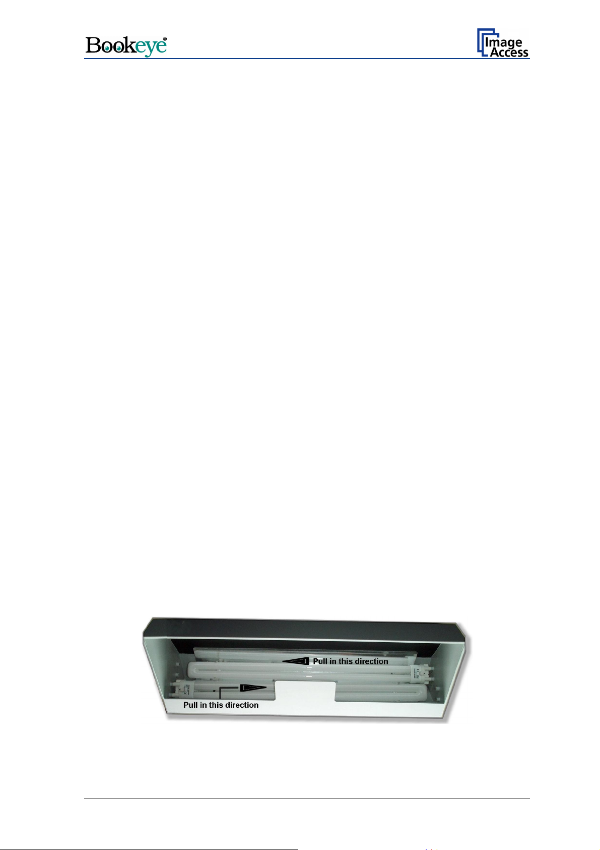
Picture 4: Lamp housing. Pull in arrow direction to unplug the lamps. 15
Picture 5: Keyboard BOOKEYE Color 18
Picture 6: Function field FORMAT 19
Picture 7: Reference with format definitions 19
Picture 8: Function field TYPE 20
Picture 9: Book fold positioned on center line 21
Picture 10: Example for document height 21
Picture 11: Distance to document bed edge 21
Picture 12: Example for document used with FOLDER 22
Picture 13: Function field PAGES 23
Picture 14: Function field COLOR 25
Picture 15: Function field BRIGHTNESS 25
Picture 16: Function field CONTRAST 26
Picture 17: Function field COPIES 26
Picture 18: Start screen 29
Picture 19: Main screen 30
Picture 20: Options screen 32
Picture 21: Book Fold Option screen 33
Picture 22: Embedded Meta Data screen 34
Picture 23: Paper screen 35
Picture 24: User defined formats screen 36
Picture 25: Prescan in UDF screen 37
Picture 26: Final scan in UDF screen 38
Operation Manual Page 7
Page 8

Table of Pictures, part 2
Picture 27: Prescan in UDF with JAVA screen 39
Picture 28: Frame in UDF with JAVA screen 40
Picture 29: Image resulting from user defined area 40
Picture 30: Camera screen 41
Picture 31: User defined resolution 41
Picture 32: Resolution selected from a drop down list 42
Picture 33: Automatic Threshold function 42
Picture 34: Black Threshold slider 43
Picture 35: Color Gain screen 44
Picture 36: Settings screen 45
Picture 37: List of available languages 45
Picture 38: Tool Tips 46
Picture 39: Status window 46
Picture 40:Output Option Show 47
Picture 41: Output Options in Scan Window 47
Picture 42: Output Option Print 48
Picture 43: Available List of Printers for Option Print 48
Picture 44: Output Option Copy 49
Picture 45: Output Option FTP Upload 51
Picture 46: Output Option Mail 52
Picture 47: Output Option Network 54
Picture 48: Security query after shutdown command 55
Picture 49: Browser message after shutdown 55
Picture 50: “Setup Device” screen 63
Picture 51: „Poweruser“ information menu 64
Picture 52: Menu in section „Adjustment & Support“ 64
Page 8 Operation Manual
Page 9

1 Introduction
Dear Customer,
We congratulate you on the acquisition of this innovative product from Image Access, Inc.
We at Image Access, Inc. are proud of the work we do, it is the result of our extremely
high standards of production and stringent quality control.
With the BOOKEYE
wide scope of applications due to its versatility. Its integrated user interface makes all
functions available in structured menus.
®
Color, Image Access, Inc. offers an efficient scanner which covers a
This operation manual is designed to lead you through all steps that will arise when using
the BOOKEYE
®
Color.
For this reason, we ask you to read the operation manual attentively before starting to
work with the device. By doing so, you will avoid operation errors and you can control all
functions from the beginning.
In addition please consider the following points:
Damages to your unit may have occurred during shipping. Please check for damages
immediately after delivery of the unit. Inform your supplier if damage has occurred.
Read and ensure that you understand the safety notes. They were developed for your
protection and safety as well as to protect the unit.
Regular maintenance conserves the high quality and safety of the BOOKEYE
®
Color
during the entire service life.
If you have any further questions, please feel free to contact your local dealer or
Image Access, Inc. directly. Our staff will be happy to help you.
For your daily work with the BOOKEYE
®
Color scanner, we wish you success and
complete satisfaction.
Regards,
Your Image Access Team
Operation Manual Page 9
Page 10

2 Safety Notes
Read and ensure that you understand the safety notes. They are devised for your
protection and for your safety.
All safety requirements of the European Standard
EN 60950, Safety of Equipment in the Information Technology,
®
are fulfilled by the scanner BOOKEYE
2.1 Marking of Safety Notes
All safety notes are marked with a prefixed warning sign.
Beside the warning sign you find a description of the danger.
Color.
Safety Note!
Example text.
2.2 Connecting to the Power Source
Important: Before connecting to the power source, check the following items:
The wall outlet is in perfect condition and properly grounded.
The power cable is not damaged in any way.
The wall outlet fuse has the correct electrical dimensions. Refer to the technical
specification chart for detailed information.
Check the device fuse. Use only the specified device fuse. The device fuse specification is
named on the identification plate.
Page 10 Operation Manual
Page 11

2.3 Device Location
Place the device on a flat and solid base.
The load bearing capacity of the base must correspond to the device weight.
Choose a location that complies with the limits of temperature and humidity. Refer to the
technical specification.
— Temperature adaptation:
A fast change from cold to warm environmental conditions will build up condensation
inside the housing. This will result in unfavorable scanned images and could cause
permanent damages to the unit.
NOTE: Before use in the new environment allow at least one hour for temperature
adaptation.
2.4 Replacing Lamps
— Switch off the device at the main power switch before replacing the lamps.
— As replacement only use original lamps with the prescribed data. Only original lamps
fulfill the light specification.
2.5 Maintenance and Repair
There are not any parts of the BOOKEYE® Color which can be repaired or maintained by
the user.
All maintenance and repairs should be done by a trained technician.
2.6 Cleaning
— Switch off the BOOKEYE
— Unplug the power cable.
— Use only solvent-free cleaner.
— Avoid penetration of liquid into the casing during the cleaning.
®
Color at the main power switch before doing any cleaning.
Operation Manual Page 11
Page 12
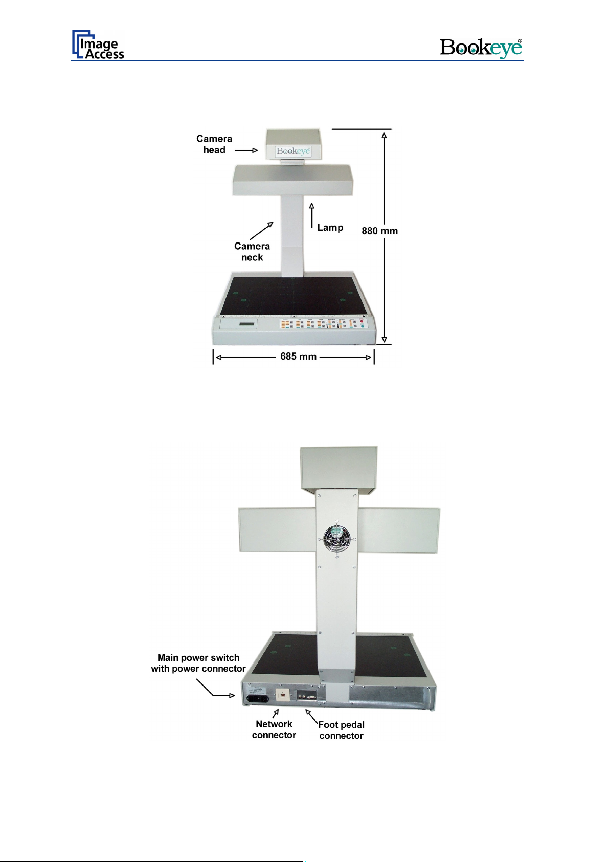
3 Device Overview
Picture 1: Front side view
For a first look at the BOOKEYE® Color, some of the more important components have
been identified in the photos here. These components are referenced in the operation
manual.
Picture 2: Details on the back side
Page 12 Operation Manual
Page 13

4 Content on Delivery
The BOOKEYE® Color scanner is delivered with the following:
• Cross-Over cable (with green connectors)
• Network cable
• Power cable
The Cross-Over cable is used to connect the BOOKEYE
computer via the network card.
The network cable connects the BOOKEYE
®
which define the BOOKEYE
Color in the network must be set prior to the first use.
The power cable connects the BOOKEYE
®
Color scanner to the network. All parameters
®
Color to the wall outlet.
®
Color scanner directly to a
Operation Manual Page 13
Page 14

5 Establishing Connections
Important: Before connecting the BOOKEYE® Color scanner to the mains voltage,
check the following items:
¾ The wall outlet is in perfect condition and properly grounded.
¾ The power cable is undamaged.
¾ The wall outlet is equipped with a correctly dimensioned fuse.
¾ Turn the device off before plugging or unplugging any cable.
Connect the wall outlet and the power supply connector at the BOOKEYE
power cable.
®
Color with the
Picture 3: Connectors on backside
5.1 Main Power
The power connector and the main power switch are located at the right side of the back
of the document bed.
After the main power switch is turned on the green START LED above the START button
lights up.
This indicates that the BOOKEYE
®
Color is ready-to-use.
5.2 Connecting the Network Cable
The BOOKEYE® Color scanner is delivered with a cross-over cable (green cable
connectors) and a network cable.
The network connector is located at the back side of the document bed.
Use the cross-over cable in order to connect the BOOKEYE
PC via a network card.
Use the network cable in order to connect the BOOKEYE
®
Color scanner directly to a
®
Color scanner to a network.
Page 14 Operation Manual
Page 15
5.3 Connecting a Foot Pedal Switch
The scan sequence can be started with optional available foot pedal switches.
At the back side are two jack plugs to which the foot pedal switches can be connected.
The jack plugs are labeled with “FS1” and “FS2”.
Note: Switch off the BOOKEYE
pedal switch to the jack plugs.
®
Color before connecting or disconnecting the foot
5.4 Possible Disturbance at Power Up
After connecting the BOOKEYE® Color to the mains voltage and turning the main power
switch on, the lamps should light up for a short moment.
This is a design-related behavior of the lamps electronic ballast.
Situation: When starting the device using the START button, one of the two lamps in the
lamp housing does not light up.
The lamp is not defective. A safety feature in the lamps electronic ballast prevents the
lamp from turning on. To resolve this situation, employ one of the two solutions, or both, if
necessary.
Important: For both solutions the following is valid: Do not turn off the main power
switch and do not disconnect the device from the mains voltage.
Suggested solution 1:
After completing the device system start-up sequence, switch the device off using the
STOP button. Chapter 6.2 describes all necessary steps.
After a short waiting period of approx. 10 minutes, the device can be restarted via the
START button. Both lamps in the lamp housing should light up now.
Suggested solution 2:
After completing the device system start-up sequence, switch the device off using the
STOP button. Chapter 6.2 describes all necessary steps.
Unplug the lamp which did not light up from the lamp socket and plug it in again.
Note: The lamps can be plugged into the lamp sockets or removed from the lamp
sockets without contact of live units.
Picture 4: Lamp housing. Pull in arrow direction to unplug the lamps.
Operation Manual Page 15
Page 16

6 Operation
6.1 Starting the BOOKEYE® Color
Press the START button.
After the BOOKEYE
sequence starts.
While the self test sequence runs, the display shows alternating in two lines:
After finishing the self test sequence and during the warm-up time of the lamps, the
display shows:
®
Color is turned on, the lamps light up and the internal self test
System Test
Please wait !!
Warm up
System test ok
At the end of the lamp warm-up time the display changes to the message:
Device version (e.g. BE2-SCL-N2)
System test ok
The BOOKEYE
illuminated:
®
Color is now ready to use. On the keyboard, the following LEDs are
Function field LED
FORMAT A3
TYPE FLAT
PAGES LEFT
COLOR COLOR
BRIGHTNESS AUTO
CONTRAST AUTO
COPIES 1
Page 16 Operation Manual
Page 17

6.2 Switching off the BOOKEYE® Color
Press and hold the STOP button for at least three seconds.
The red STOP LED starts blinking.
The lamps and all LEDs on the keyboard will be switched off.
During the shutdown sequence the display shows
System Shutdown
*******************
At the end of the shutdown sequence only the green LED above the START button
remains on.
The BOOKEYE
6.2.1 Special Case: Switching off by STOP Key Not Possible
®
Color is now in stand-by mode.
If the BOOKEYE® Color cannot be switched off due to a system disturbance, the device
can be powered down with the main switch.
Note: After switching off using the main switch, more time is necessary for the
subsequent system start since all system parameters have to be restored.
If the BOOKEYE
react with a delay on commands from the user interface.
®
Color is installed in a network with a high number of users, it might
Operation Manual Page 17
Page 18

7 Keyboard
Picture 5: Keyboard BOOKEYE Color
The keyboard is laid out in seven function fields. At each function field, upward/downward
buttons are used to select the desired setting.
The selected setting is displayed by LEDs at each function field.
The START button and the STOP button control several functions. The function of these
®
buttons is defined by the mode of operation of the BOOKEYE
The BOOKEYE
®
Color has two modes of operation.
— Scan mode: In this mode of operation the BOOKEYE
Color.
®
Color is controlled by the
function fields or by the integrated user interface.
Pressing the START button starts the scan sequence with the
defined parameters. During the scan sequence the display shows
the current status.
A brief push of the STOP button interrupts the scan sequence. All
scanned data is lost.
Pressing the STOP button for at least three seconds switches the
BOOKEYE
®
Color off. While switching off, the red LED blinks.
During this time the display shows the current status.
At the end of the shutdown sequence, the green LED above the
START button lights up. The BOOKEYE
®
Color now is in stand-by
mode.
— Set-up mode: In this mode of operation all specific device parameters of the
BOOKEYE
®
Color are set.
For this purpose, five function fields of the keyboard are used.
Detailed information about the setting of device parameters can be
found in chapter 8.
Page 18 Operation Manual
Page 19
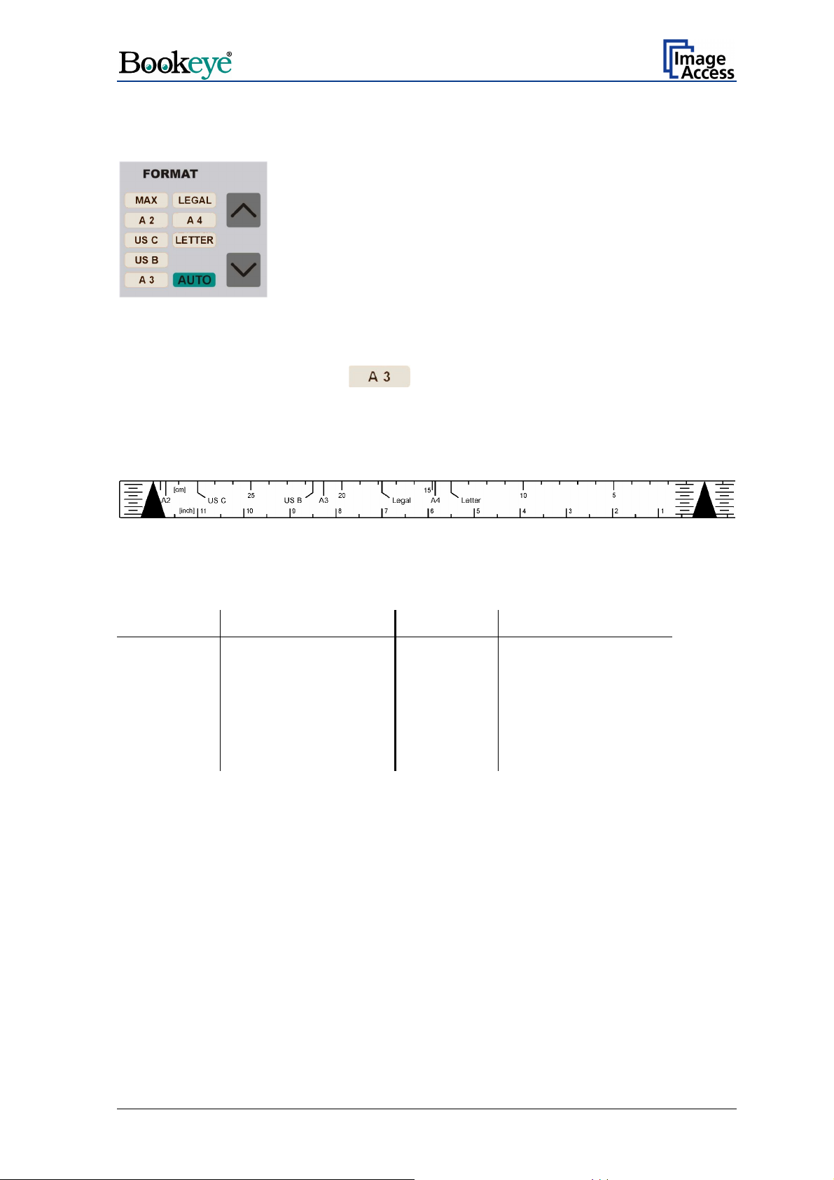
7.1 FORMAT
Picture 6: Function field FORMAT
The function field FORMAT defines the size of the scanned area.
At the end of the system-test the
The size, indicated by the LED, always refers to the horizontal format. For easy orientation
above the keyboard, a format reference can be found. The available formats are marked
on this reference.
All formats defined on the reference are center symmetric.
Picture 7: Reference with format definitions
Table 1 indicates the dimensions of the scanned area.
Lettering Size Lettering Size
MAX Maximum scan area LEGAL 215,9 x 355,6 mm
A2 420 x 594 mm A4 210 x 297 mm
US C 431,8 x 558,8 mm LETTER 215,9 x 279,4 mm
US B 249,4 x 431,8 mm
A3 297 x 420 mm AUTO Automatic size detection
field lights up.
Table 1: Size of the scanned area
The “AUTO” setting activates the automatic size detection.
By using the “AUTO” setting, the BOOKEYE Color scans the complete, maximum scan
area. The size of the document which is placed on the document bed is recognized
automatically and displayed in the correct size.
Operation Manual Page 19
Page 20
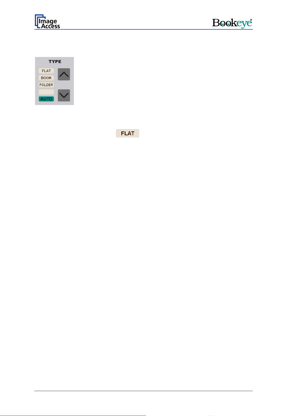
7.2 TYPE
Picture 8: Function field TYPE
The function field TYPE defines the document type.
At the end of the system-test the
Function Document type
FLAT Documents with consistent thickness, e.g. single pages.
Documents without binding or center fold.
BOOK Documents with a high center fold, e.g. books, catalogues or similar
things.
FOLDER Documents with distinct differences in level, e.g. opened files.
AUTO No function at this time.
field lights up.
7.2.1 FLAT
The type FLAT is suitable for all documents with a slight difference or no difference in
thickness level over the whole document.
If the type FLAT is selected, the focus value is measured in a narrow range to the left,
next to the center line of the document bed. The distance to the center line results from
the size of the document to be scanned. Place the document at the edge of the document
bed and with at least a third of the document size left from the center line.
With the setting PAGES Æ RIGHT, the focus value is measured right from the center line.
In this case, place the document so that at least a third of the document size is right of the
center line.
The distance between the measurement area and the center line depends on the selected
format. The smaller the selected format is, the closer the measuring area is to the center
line.
Page 20 Operation Manual
Page 21

7.2.2 BOOK
The type BOOK is suitable for bounded or stitched documents with a high center fold, the
so called “book fold”.
The setting BOOK activates the Book Fold Correction.
The following criteria must be met for proper functioning of the Book Fold Correction:
— The middle of the book fold must be positioned on the center line.
Picture 9: Book fold positioned on center line
— The document must not be positioned at the document bed edge. The distance
between document and document bed edge should be at least half of the document
height.
Picture 10: Example for document height
Picture 11: Distance to document bed edge
If these criteria are not met, the BOOKEYE Color produces an uncorrected image.
Operation Manual Page 21
Page 22
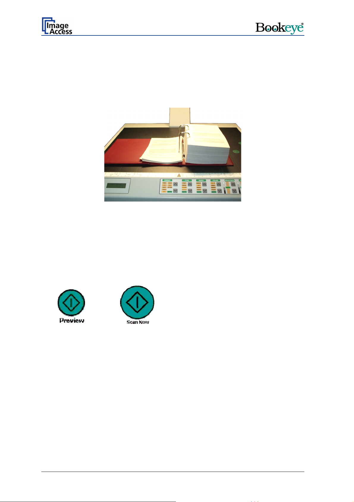
7.2.3 FOLDER
The type FOLDER is suitable for documents with plain differences in levels between left
and right page.
These are e.g. extensive files or documents without bound or center fold.
Picture 12: Example for document used with FOLDER
In combination with the setting PAGES Æ BOTH, the left and right half of the document
are focused and sent separately.
Because of the separate focusing for each side, it is not necessary to take the documents
out of the file.
The second side is sent after further pushing the START button or by clicking again the
buttons
Scan Preview Now
Or
in the integrated user interface.
Chapter 9 describes the functions and the use of the integrated S2N user interface.
Scan Now
Page 22 Operation Manual
Page 23

7.3 PAGES
Picture 13: Function field PAGES
The function field PAGES defines the output mode.
At the end of the system-test the
The settings LEFT, RIGHT and BOTH activate the page separation.
Function Output mode
SINGLE No page separation. Selected document size as one image.
LEFT Page separation activated. Output of the left half of the selected scan
area size.
RIGHT Page separation activated. Output of the right half of the selected scan
area size.
BOTH Page separation activated. Output of the left and right half of the
selected scan area size consecutively.
AUTO No function at this time.
field lights up.
Operation Manual Page 23
Page 24

Examples:
Selected setting
Example 1:
Function field FORMAT: A4.
Function field PAGES: SINGLE.
Example 2:
Function field FORMAT: A3.
Function field PAGES: LEFT
Scan area (white area)
Example 3:
Function field FORMAT: A3
Function field PAGES: RIGHT
Page 24 Operation Manual
Page 25

7.4 COLOR
Picture 14: Function field COLOR
The function field COLOR defines the color mode.
At the end of the system-test the
Function Output mode
COLOR Scans the document in 24-bit color mode.
GRAY Scans the document in 8-bit gray scale mode.
PHOTO Scans the document in bi-tonal (black/white) mode combined with a
dithering effect. The readability of details in the scan is improved by the
dithering.
B & W Scans the document in bi-tonal (black/white) mode.
AUTO No function at this time.
field lights up.
7.5 BRIGHTNESS
Picture 15: Function field BRIGHTNESS
The function field BRIGHTNESS sets the brightness value while scanning.
At the end of the system-test the
Moving the LED bar upwards increases the brightness. Moving the LED bar downwards
decreases the brightness.
Operation Manual Page 25
field lights up.
Page 26

7.6 CONTRAST
Picture 16: Function field CONTRAST
The function field CONTRAST sets the contrast value while scanning.
At the end of the system-test the
Moving the LED bar upwards increases the contrast value. Moving the LED bar
downwards decreases the contrast value.
field lights up.
7.7 COPIES
Picture 17: Function field COPIES
This function field is only active in the copier version of the device.
At the end of the system-test the
The function field COPIES selects the number of copies.
field lights up.
Page 26 Operation Manual
Page 27
8 Set-up Mode
In set-up mode, the user can set different parameters of the BOOKEYE Color.
8.1 Activating the Set-up Mode
The BOOKEYE Color must be off.
Press and hold the STOP button and then press the START button.
The lamps light up and the display shows in two lines:
Self Test
KBD vers.
This message will be displayed until the end of the internal self-test sequence.
(version number)
During the internal self-test sequence, all LEDs on the keyboard light up consecutively
After the self-test is completed, the LEDs light up in the same position which was active
when the device was switched off.
The display now shows the serial number of the BOOKEYE Color in two lines.
.
8.2 Checking the current settings
To check the current settings of the IP address, the subnet mask, the gateway address
and DHCP value, perform the following steps.
Press the up / down buttons at the FORMAT keyboard field to select the displayed value.
Serial number of the device (e.g. BE2-SCL-N2)
Serial number of the device
IP:
AAA.BBB.CCC.DDD
Subnet:
AAA.BBB.CCC.DDD
The display shows …
Gateway:
AAA.BBB.CCC.DDD
DHCP
YES / NO (displayed value depends on the current setting)
Operation Manual Page 27
Page 28

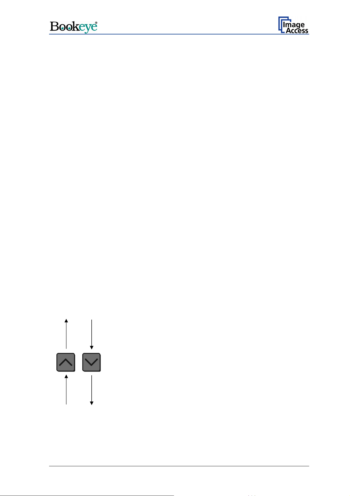
8.3 Setting new values
To set new values for the displayed parameters, use the following buttons:
— Use the up / down buttons at the function field TYPE to change the value for AAA as
well as to switch the setting for DHCP between YES and NO.
— Use the up / down buttons at the function field PAGES to change the BBB value.
— Use the up / down buttons at the function field COLOR to change the CCC value.
— Use the up / down buttons at the function field BRIGHTNESS to change the DDD
value.
Press the corresponding button to increase or decrease the desired value.
Press the button continuously to change the values fast upwards or downwards.
8.3.1 Special advice for the gateway address setting
If no gateway is used, use the same address as for the IP address setting.
8.4 Saving new values
Press and hold the START button for at least one second to save the new value.
The display shows the following message.
Settings stored
Please reboot
After this message, the display returns to the serial number.
8.5 Ending the Set-up Mode
To end the set-up mode, press and hold the red STOP button for at least three seconds.
The red STOP LED starts blinking.
The display shows the message:
System Shutdown
****************
The lamps and all LEDs on the keyboard will be switched off.
After the power-down sequence is finished, only the green START LED remains on.
Page 28 Operation Manual
Page 29

9 The Integrated User Interface
Start your browser.
Enter the IP address of the scanner.
The start screen of the integrated user interface opens.
Picture 18: Start screen
Click the button Launch Scan Application .
Operation Manual Page 29
Page 30

The main window of the integrated user interface opens.
Picture 19: Main screen
The main window is structured into three parts.
The part on the right side shows a menu bar with four menu items:
¾ Options
¾ Paper
¾ Camera
¾ Settings
Page 30 Operation Manual
Page 31
The seven control buttons in the lower part of the screen control the output modes.
As default the output mode
Show is selected. After clicking onto the button Preview or
Scan Now a window opens and shows the image.
When selecting
Save the scanned image will not be displayed, instead of the second
window a box opens where the desired directory can be set.
Selecting
Print will display the scanned image in a second window and direct the scanned
image to locally available printers.
Selecting
Selecting
Selecting
Selecting
Copy prints directly to a previously installed network printer.
FTP Upload scans directly a FTP server.
Mail sends the scanned image directly to a previously defined e-mail address.
Network uploads the scanned image directly to a previously defined workstation
in the network.
The frame on the left side shows the buttons for preview scan and main scan.
Note: Pressing the red STOP button
switches the scanner off.
If the STOP button is pressed, the following window will appear.
Operation Manual Page 31
Page 32

9.1 The Options Screen
Picture 20: Options screen
Picture 20 shows all selectable options.
The
Color Mode allows the user to select various different color modes. True color, gray
scale binary and indexed color are some of the possible choices.
The
File Format defines the file format that is used to store a scanned file. There are
some relations between this control and the control right beside. For example, it is not
possible to store a true color image in Tiff G4 file format.
The
JPEG Quality determines the compromise between quality and compression rate. A
higher quality factor produces larger files. The default setting of 75 is a good compromise
for most documents.
The
Document Mode selects between different types of documents.
• In
• In the
Flat Mode the document is treated flat, i.e. with a fixed focus setting regardless of
the actual shape of the document. This mode avoids out of focus problems when
scanning three dimensional objects that cannot be described as folders or books.
Book Fold Correction mode the focus follows the surface of a book while the
scanner advances from left to right or right to left. Also all geometric distortions are
compensated for. For optimal results it is essential that the book is aligned straight to
the green line which marks the middle of the document bed. More details can be
specified in the
(Options) (see chapter 9.1.1) dialog.
• In the Folder Mode the focus is fixed on the right side and the left side of the
document independent of each other. To get optimal results it is essential to align the
open folder straight to the green line which marks the middle of the document bed.
Page 32 Operation Manual
Page 33

The Scan Mode defines the scanning speed. If High Quality is selected, the scanning
speed is reduced to the half.
The
Preview value sets the size of the preview image. If set to Auto the function will
perform a best fit before the image is displayed on the screen.
Image Rotation can be any degree of rotation out of 90°, 180°, 270° or none. The
The
angle is defined in the clockwise direction.
The
Embedded ICC switch is either Yes or No.
Embedded Meta Data switch is either Yes or No. More details can be specified in
The
(Option) dialog.
the
9.1.1 Book Fold Options
Picture 21: Book Fold Option screen
Clicking on the (Options) opens an additional window. It allows to set the value for the
margins, the left and the right center position as well as the threshold value. The unit of
measurement can be set by the list on top of the window.
Operation Manual Page 33
Page 34

9.1.2 Embedded Meta Data
Picture 22: Embedded Meta Data screen
This function is used in conjunction with the file formats JPEG, TIFF or PDF. It will allow
the operator to include a set of XMP/RDF compliant document metadata in the file header.
Select Yes or No, click on
configuration window will open.
Metadata Description
Author Enter the name or organization that created the document
Title Enter a short title for the scanned document.
Subject Abstract of the document.
Copyright Marker Select if the scanned document is copyright protected.
Copyright Information Enter the copyright message. This message will be only
URL of extended Copyright
Information
(Options) to define a set of XMP/RDF compliant metadata. A
or is the copyright owner of the document.
embedded in the scanned document if the copyright marker
is set to “yes”.
Enter an external URL which shows a detailed copyright
message.
Keywords
(comma separated list)
Note: Each change of an entry field is transferred to the scanner immediately.
Page 34 Operation Manual
Enter a list of comma separated keywords which describe
the content of the document.
Page 35

9.2 The Paper Screen
Picture 23: Paper screen
The Format selects between various standard paper formats. If Auto is selected, the
scanner scans the maximum format and then crops the document to its real size. This
function is highly advanced and works with default values most of the time. Nevertheless
is can also be statically configured with the two additional sliders on the right side.
Some
units of pixels.
The
that are darker are considered background and will be used to find the borders of the
document.
The
scan is performed.
Additional Margin can be added to or taken away from the image. It is defined in
Background Density value defines the brightness level of the background. All areas
Splitting Image button allows splitting the image into two pages although only one
Operation Manual Page 35
Page 36
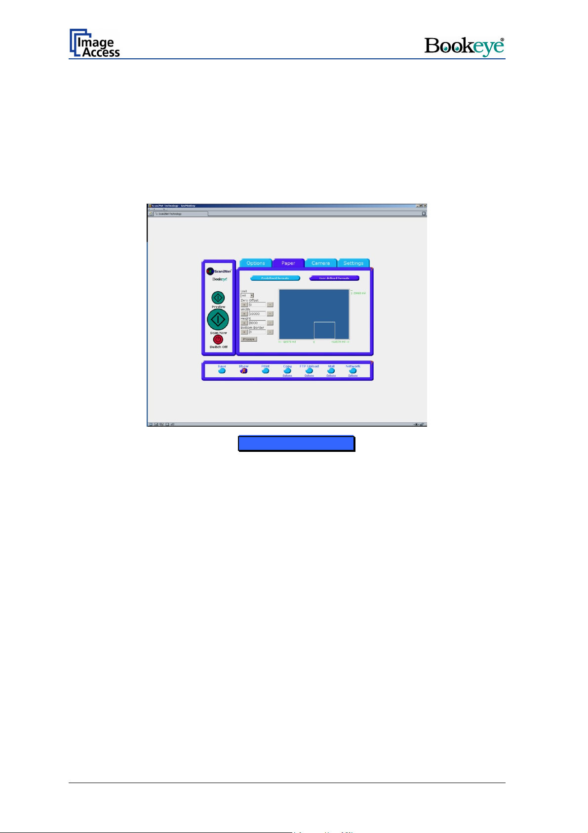
9.2.1 User defined Format, no JAVA
The size of the user defined formats can be specified in two ways.
1. If no JAVA Plug-In is installed, the size and the position of the scan area can be
defined via numerical values.
2. If the option Use Java UDF in the
the user defined scan area are defined via a rectangle drawn with the mouse.
Picture 24: User defined formats screen
Settings menu is activated, the size and position of
In the middle of the selection window, the whole scan area is represented with a blue
template. The size of the user defined scan area is shown with a red dashed line
rectangle.
The position marked with 0 (zero) corresponds to the middle of the lower edge of the
document bed.
At the lower left corner, the maximum value of the scan area to the left direction is shown.
At the lower right corner, the corresponding maximum value in the right direction is shown.
At the upper right corner, the maximum height value of the scan area is shown.
The unit of the maximum values shown depends on the
scan area. Valid choices are:
• mil (1/1000 Inch)
• inch
• cm
• mm
• pixels.
unit control left of the schematic
Page 36 Operation Manual
Page 37

After clicking the Preview button, a preview of the whole scan area will replace the
template. The red dashed line rectangle will now visualize the selected scan area.
Picture 25: Prescan in UDF screen
At the left side of the schematic scan area the numeric controls are arranged.
The value for the Zero Offset defines the shifting to the right or to the left starting from the
middle of the lower edge of the document bed.. The + button increments the shown value
by 1, the – button decrements the shown value by 1. Any change of the set value will
change the size of the red dashed line in the schematic scan area.
The value for the Bottom Border defines the vertical shifting of the scanned area from
the lower edge. The + button increments the shown value by 1, the – button decrements
the shown value by 1. Any change of the set value will change the size of the red dashed
line in the schematic scan area.
The value for the Width defines the horizontal width of the scanned area starting from the
left edge of the red dashed rectangle. The + button increments the shown value by 1,
the – button decrements the shown value by 1. Any change of the set value will change
the size of the red dashed line in the schematic scan area.
The value for the Height defines the vertical height of the scanned area starting from the
bottom edge of the red dashed rectangle. The + button increments the shown value by 1,
the – button decrements the shown value by 1. Any change of the set value will change
the size of the red dashed line in the schematic scan area.
Operation Manual Page 37
Page 38

The maximum size of each value depends on the other one in the same direction:
Maximum (vertical) = Bottom Border + Height
Maximum (horizontal) =Zero Offset + Width
If one of the allowed maximum values is exceeded, the entered values will be ignored and
the maximum valid value will be displayed.
Note: Each change of an entry field is transferred to the scanner immediately.
After defining the scan area click the Scan Preview Now button or the Scan Now button
to start the scan sequence.
When the scan sequence is complete an image with the selected size is displayed
Picture 26: Final scan in UDF screen
Page 38 Operation Manual
Page 39

9.2.2 User defined Format, with JAVA
The Java UDF allows to select the scan area from a preview with a mouse. For using the
Java UDF an installation of the Java run time environment (JRE) is required. The Internet
Explorer and most common third party internet browsers usually offer a preinstalled JRE.
In the browser the execution of Java programs must be allowed.
The SUN JRE version 5.06 or newer is recommended, although the Java UDF is
compatible with all JRE versions down to version 4.0.
At first click on the tab Settings and set Use Java UDF to Yes (refer to chapter 9.4).
Return to the Paper screen.
Then click on User defined formats. After a short moment the preview scan is displayed.
The preview scan shows the complete scan area including the document.
Picture 27: Prescan in UDF with JAVA screen
Operation Manual Page 39
Page 40
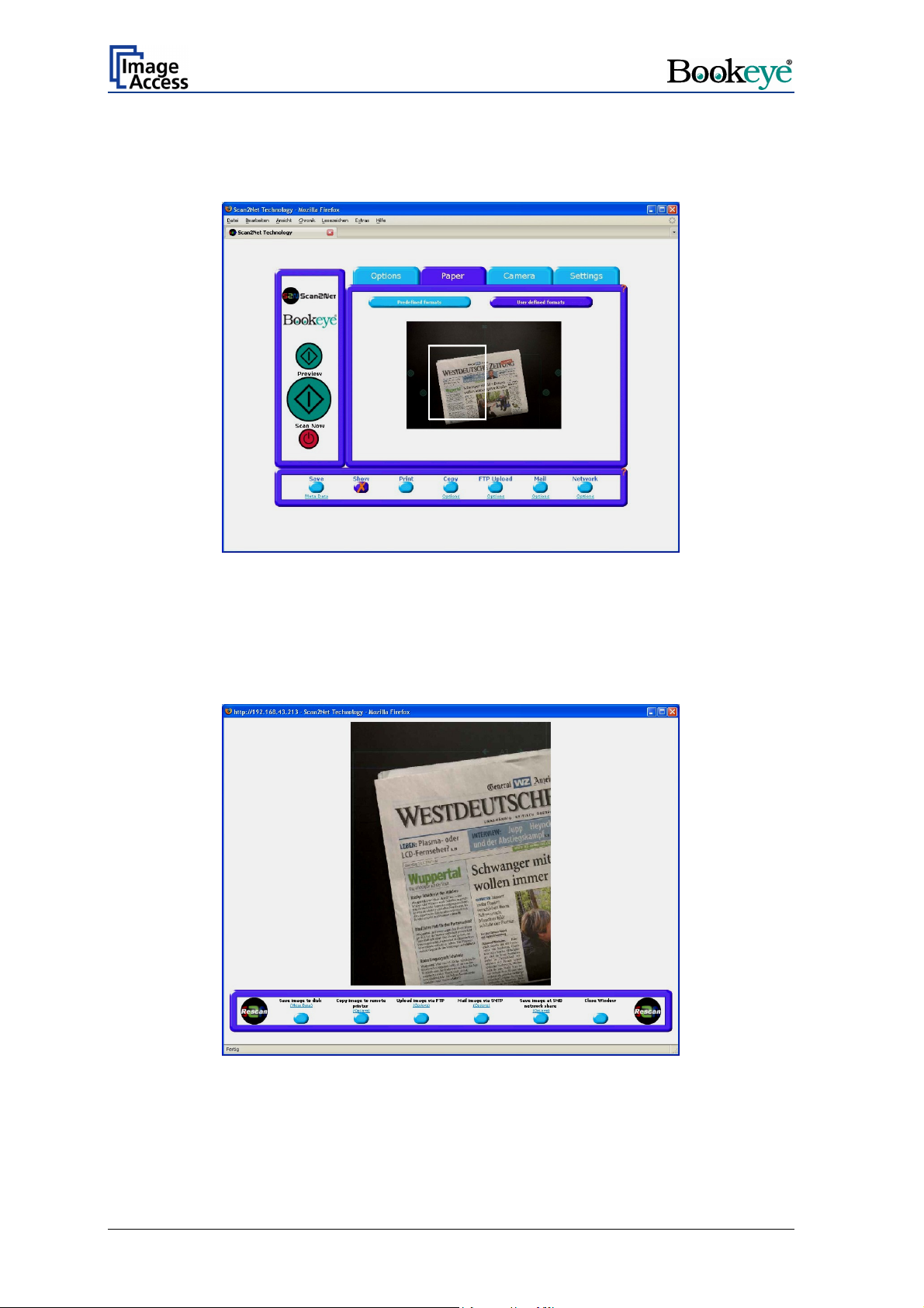
Select the scan area by clicking into the preview scan with the mouse, hold the left mouse
button pressed and draw a frame with the desired size. The frame will have a white
outline.
Picture 28: Frame in UDF with JAVA screen
After the scan area is defined click the Scan Preview Now button or the Scan Now
button to start the scan process.
When the scan sequence is complete an image with the selected size is displayed.
Picture 29: Image resulting from user defined area
Page 40 Operation Manual
Page 41

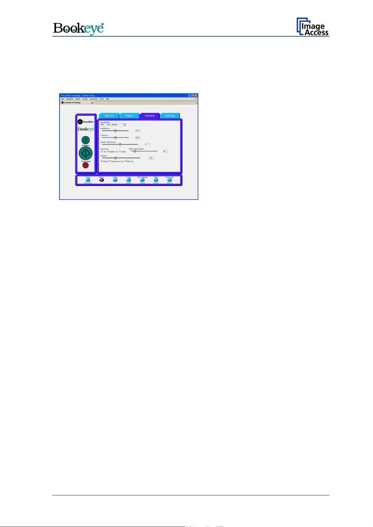
9.3 The Camera Screen
Picture 30: Camera screen
The resolution can be set in two ways:
• The input field left below
400 dpi in steps of one dpi. When the resolution is set in such a way, the field right
below
Resolution indicates user defined.
Resolution allows to key in any value between 150 dpi and
Picture 31: User defined resolution
Operation Manual Page 41
Page 42

Picture 32: Resolution selected from a drop down list
• The right field below Resolution offers a drop down list. Available are 150, 200, 240,
300 and 400 DPI.
If the resolution is selected from the list both fields show the same value.
The
Brightness slider defines the brightness of the resulting image. Lower brightness
values make the image darker.
Contrast slider defines the contrast of the resulting image. Higher contrast values
The
show more details.
If scanning in binary mode (i.e. Line Mode,
Photo Mode), the
function will be showed. If the
Threshold
all. If the
is off, the slider has no function at
Automatic Threshold is on, the
Automatic Threshold
Automatic
contrast slider defines the reaction time of the
automatic background tracker.
Picture 33: Automatic Threshold function
Note: Use the contrast slider carefully in the automatic threshold mode because if set to
the extremes, unexpected image artifacts may occur.
Page 42 Operation Manual
Page 43
The Image Sharpness slider invokes an advanced algorithm which sharpens the image
according to the local content of a given area.
The
Exposure function sets the threshold value for the black cut function or for the auto
exposure function.
No disables the exposure function.
When Black Cut or Auto is selected
an additional slider is displayed.
Picture 34: Black Threshold slider
Black Cut
0 (zero) to 100
Auto
0 (zero) to 100
Sets the threshold for black. All pixel values found in the image below
the selected value are set to black.
Result: The image contrast is improved.
Sets the threshold for black and activates the automatic exposure
control.
This function searches the image for the highest and the lowest pixel
value. The highest pixel value is defined as “white”. Is the lowest pixel
value higher than the threshold it is defined as “black”. Otherwise all
values below the threshold are defined as “black”.
Result: Automatic contrast control and the image contrast is improved.
Operation Manual Page 43
Page 44
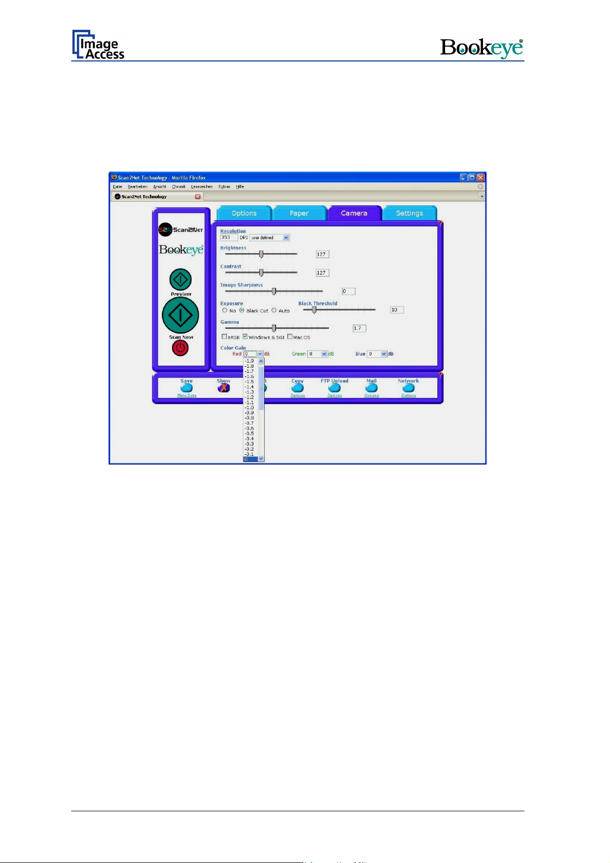
The Gamma slider does the gamma correction directly inside the camera electronics.
Three typical values are predefined on the
The
Color Gain drop down list changes the gain on a specific color channel. This function
is used to eliminate any color shift or tints from the background.
Preselection buttons.
Picture 35: Color Gain screen
Page 44 Operation Manual
Page 45

9.4 The Settings Screen
Picture 36: Settings screen
The Language Selector offers a drop down list of languages for the S2N user interface.
Picture 37: List of available languages
Currently available languages are english, deutsch, français, and russian. If russian is
selected, all text are displayed in Cyrillic fonts.
The S2N user interface shows all texts in the selected language immediately after
switching.
Operation Manual Page 45
Page 46

The Skin Selector offers different surfaces (skins) for the user interface. Currently
available surfaces are application, classic and classic-green, classic-light and metal.
Other skins can be designed and integrated by the user.
Picture 38: Tool Tips
Tool Tips can be activated to inform the user with short texts about the available
functions in each screen. With the drop down list the delay time can be defined. Selecting
No Tool Tips switch this function off.
Picture 39: Status window
Show Status Window turns on and off the display of a scanner status window. Click the
Yes button to activate this window.
Use Java UDF (UDF = User Defined Formats) activates the JAVA Plug-In for setting the
UDF of the scan area.
If No is selected, the JAVA Plug-In is not active. The dimension of the user defined format
of the scan area can be defined with numeric values.
Page 46 Operation Manual
Page 47

9.5 Output Options
There are various output options available on a Scan2Net scanner. In most cases, the
button
Show is activated.
Picture 40:Output Option Show
A scan will open a new browser window and display the image on the screen. The output
options described in this chapter are accessible via the above menu but are also present
in the lower part of each scanned image.
Picture 41: Output Options in Scan Window
Their functionality is identical, therefore only the output option screen is described here.
9.5.1 Output Option Save
This output option scans to the local disk drive. After the scan is performed, a window
opens and the default file name is shown. The user can select local and network drives for
the save location and can also change the file name before it is actually stored.
Operation Manual Page 47
Page 48

9.5.2 Output Option Print
This output option prints to the locally available printers. After the scan is executed, the
standard windows printer interface is opened. The user can select one of the locally
available printers.
Picture 42: Output Option Print
Picture 43: Available List of Printers for Option Print
Page 48 Operation Manual
Page 49

9.5.3 Output Option Copy
This output option prints directly to a previously installed network printer. The (Option)
key is used to configure the remotely connected printer.
Picture 44: Output Option Copy
Remote Printer Description
Printer Preset Choose a printer configuration out of five possible set of
parameters. If you click on “Change Name” you can change
the name of this set.
Address Enter the IP address of the remote printer.
Port (9100) Enter the IP port of the remote printer. Default is port 9100.
Connection Timeout Choose the timeout for connecting to the remote printer
before the connection is aborted.
Data Format Choose the data format of the remote printer. Selectable
are Postscript, Postscript with framing HP/PJL
communication and HP DesignJet (HP/RTL) compliant
printers. Changing the data format will change some of the
options in this configuration window.
Resolution Select the printing resolution. If an exact 1:1 copy of the
scanned document is required, the scanning resolution and
printing resolution must match.
Paper Format (Postscript) Choose the paper format for postscript printer output.
Duplex Print Switch on/off printing both sides of a paper sheet (duplex).
Paper Feed Select the paper feed method for the remote printer. The
menu may contain manual paper feed, various paper trays
and paper rolls.
Operation Manual Page 49
Page 50

Remote Printer Description
Copies Number of copies of each print
Color Matching Select the color rendering method for the remote printer.
Best Fit: The printer uses the nearest matching colors of
its own color space.
Printer Color Range: The printer uses the full range of its
color space despite of the color definition of the scanned
document.
Only available in conjunction with HP/PJL communication
framework.
Edge Anti Aliasing Switch on/off printer featured edge anti aliasing.
Only available in conjunction with HP/PJL communication
framework.
Quality Level (DesignJet) Toggle the printing quality from draft to high quality.
Only available with HP/RTL compliant remote printers.
ICC Profile Select the profile used for printing. One can upload a set of
printer ICC profiles in the Poweruser setup.
Only available with HP/RTL compliant remote printers.
Brightness Modify the brightness level of the print.
Only available with HP/RTL compliant remote printers.
Contrast Modify the contrast level of the print.
Only available with HP/RTL compliant remote printers.
Gamma Modify the printer gamma.
Only available with HP/RTL compliant remote printers.
Note: Each change of an entry field is transferred to the scanner immediately.
Page 50 Operation Manual
Page 51

9.5.4 Output Option FTP Upload
Picture 45: Output Option FTP Upload
The scanner can directly scan to a FTP server. Go to (Options) to configure the FTP
interface. A configuration window will pop up.
FTP Upload Description
Address Enter the IP address of the remote FTP server.
Port (9100) Enter the IP port of the remote FTP server.
Default is port 21.
Login Enter the user name for the login at the remote FTP server.
Password Enter the password for the login at the remote FTP server.
The password is stored using encryption.
Upload Path Enter the upload path at the remote FTP server, starting
with / (root). If you click on the icon, you can browse the
directory structure of the remote FTP server. Note: You
must have a valid login for browsing the directory structure.
File name prefix Enter the file name prefix. A time stamp will be added to
this prefix to form the complete file name.
Use a FTP Proxy ? Switch on/off the use of a FTP proxy for connecting to a
remote FTP server outside the local network.
FTP Proxy Address Specify the IP address of the FTP proxy.
Port Specify the IP port of the FTP proxy.
Note: Each change of an entry field is transferred to the scanner immediately.
Operation Manual Page 51
Page 52

9.5.5 Output Option Mail
Picture 46: Output Option Mail
The scanner can directly e-mail each scan. Go to (Options) to configure the mail
interface. The above configuration window will pop up.
Mail Upload Description
Transaction mode Choose if all scanned documents will be send to the same
receiver (automatic batch mode) or if the scanner should
ask after every scan (interactive).
Address Enter the IP address of a external mail (SMTP/LMTP)
server.
Port (25) Enter the IP Port of an external mail server.
Default: Port 25.
Server authentication Does this mail server require an authentication?
Login Enter the user name for authentication at the external mail
server.
Password Enter the password for authentication at the external mail
server. The password is stored using encryption.
Protocol Choose the connection protocol. SMTP is the most
common protocol.
Connection Timeout Choose the timeout for connecting to the external mail
server before the connection is aborted.
File name prefix Enter the file name prefix. A time stamp will be added to
this prefix to form the complete file name.
Page 52 Operation Manual
Page 53

Mail Upload Description
Recipient Type in the recipient of the e-Mail.
Format: fully qualified e-Mail address.
Sender Type in the sender of the e-Mail.
Format: fully qualified e-Mail address.
Mail subject Type in the e-Mail subject.
Reply to Type in a reply address for answers.
Format: fully qualified e-Mail address.
Force disposition
notification?
Request for a notification when the recipient has opened
the mail. Note: This feature is not supported by all mail
servers or clients.
Note: Each change of an entry field is transferred to the scanner immediately.
Operation Manual Page 53
Page 54

9.5.6 Output Option Network
Picture 47: Output Option Network
SMB is a network protocol which is used by Microsoft windows based networks. Go to
(Option) to configure the SMB Upload interface. A configuration window will pop up.
SMB Upload Description
Master Browser Enter the windows network name (without the leading //) of
the server which stores the complete list of all connected
windows workstations. Typically the master browser is
identical with the WINS server.
Port (139) Enter the IP port of the SMB network communication.
Default is port 139.
Login Enter the user name for the login at the windows
workstation/file server which you want to connect to.
Password Enter the password for the login at the windows
workstation/file server which you want to connect to. The
password is stored using encryption.
SMB Path Enter the upload path at the windows workstation, starting
with a single / (root). If you click at the icon you can browse
the workstation/server list and the directory structure of the
windows workstation/file server. Note: You must have a
valid login for browsing the directory structure.
File name prefix Enter the file name prefix. A time stamp will be added to
this prefix to form the complete file name.
Note: Each change of an entry field is transferred to the scanner immediately.
Page 54 Operation Manual
Page 55
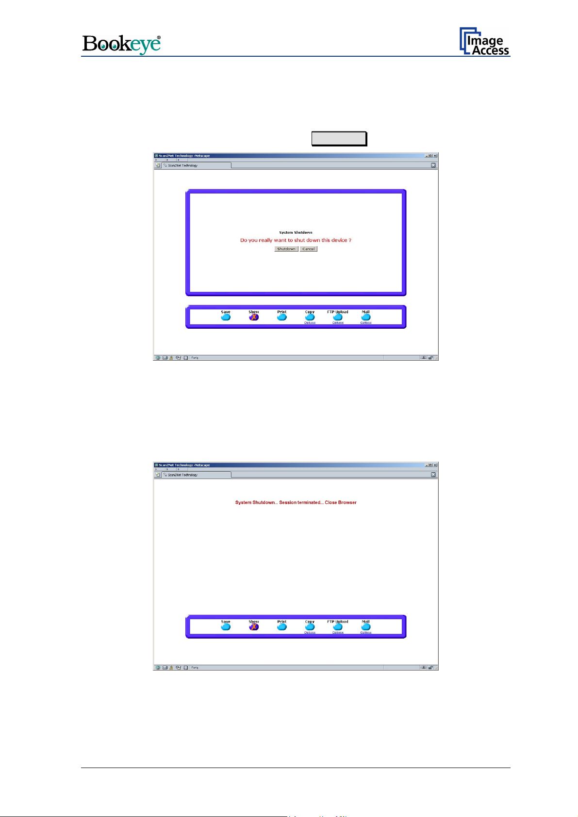
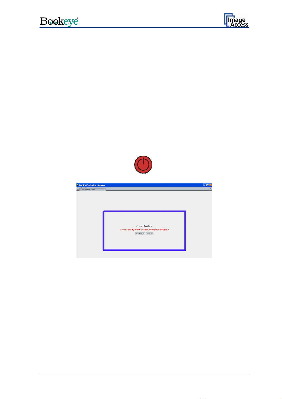
9.6 Turning off the device
Click the red STOP button to switch off the device.
A window with a security query opens. Click the Shutdown button.
Picture 48: Security query after shutdown command
After confirming the query the lamps switch off and the display shows the message:
System Shutdown
****************
After the device is switched off, the browser window shows the final message.
Picture 49: Browser message after shutdown
Operation Manual Page 55
Page 56

10 Scanning
Select the output settings by clicking one of the buttons for output mode.
If necessary set the options for the desired mode.
Set all desired settings for the scan sequence as described in chapters 9.1 to 9.5.6.
It is recommended to select the paper format AUTO from Paper, Predefined Formats.
If the option Book Fold Correction is not installed, place the document at the document
bed edge. In all other cases place the document in the middle of the document bed. For
more details see chapter 7.2.1 to 7.2.3.
Click the button “ Scan Preview Now” to see a preview image with reduced quality.
Click the button “Scan Now” to display the image in high quality and resolution.
Page 56 Operation Manual
Page 57

11 Scan2Net Firmware Update Procedure
11.1 Basic requirements
A basic requirement for a successful firmware update is to configure the browser as
follows:
• Set your browser to direct access to internet
or if you are connected via a proxy:
• Enter the scanner’s IP address in the exception list.
Additionally it is necessary to force the browser to reload the page content every time
directly from the scanner and not to load from the cache memory.
Refer to chapter 12.1 for the settings in Netscape Navigator.
Refer to chapter 12.2 for the settings in MS Internet Explorer.
Operation Manual Page 57
Page 58
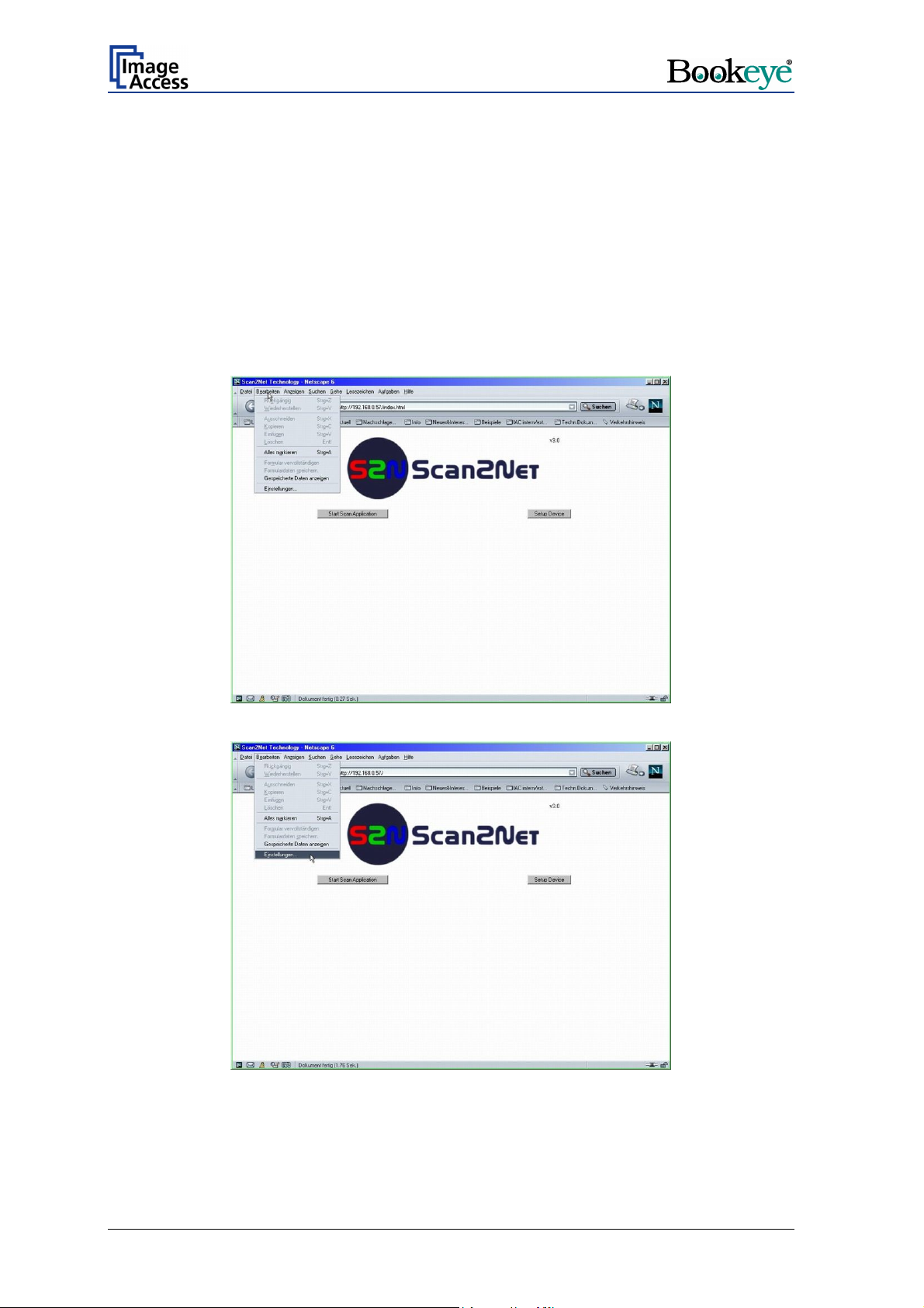
12 Browser settings for …
12.1 … Netscape 6
Note: Pictures show German version of the browser.
Start your browser and select the menu item as displayed in the pictures below. The arrow
in the screenshots points on the item which has to be selected.
Page 58 Operation Manual
Page 59

The marked menu item, shown in the picture above, forces the browser to reload the page
content each time when it is selected.
Operation Manual Page 59
Page 60

12.2 … Internet Explorer 6
Note: Pictures show German version of the browser.
Start your browser and select the menu item as displayed in the pictures below. The arrow
points on the item which has to be selected.
The marked menu item, shown in the picture beside,
forces the browser to reload the page content each
time when it is selected.
Page 60 Operation Manual
Page 61

13 Updating the Firmware
13.1 Download
Current firmware updates for your scanner are available in the Customer Service Portal of
Image Access’ internet page.
Execute the following steps to update the scanner firmware.
1. Start your internet browser and enter the Image Access internet page address:
http://www.imageaccess.de
2. Follow the link Support, Downloads Î Customer Service Portal
3. The user name “Guest” as well as the password “Guest” (case sensitivity) is pre-set.
Click the send button.
4. Click on Actions Î Download S2N Device Updates.
5. Enter the serial number and the firmware version number of your scanner. Consider
the example, while entering the serial number. Click on continue.
The next window shows the firmware version which is available for download.
The file is named s2nfirm-x.yy.zip, where “x.yy” stands for the firmware version
number. For example: s2nfirm-4.04.zip
Additionally you will get an information whether this is the current firmware version.
Information text Resulting action
Return to get newer
version after update is
installed.
The most recent version is
already installed. No action
required.
6. Save the file and/or the files in a directory which is accessible from your scanner.
When the downloads are finished, install the firmware updates in ascending order.
Further firmware versions are available to download. Repeat
step 1 to 6 up to the most current firmware version. While
repeating the steps, always enter the number of the
software saved at last.
No further actions are necessary.
Operation Manual Page 61
Page 62

13.2 Install
1. Start the BOOKEYE Color scanner.
2. When the start screen appears, click the Setup Device button.
3. Choose the login level Poweruser.
4. Login with user name “Poweruser” and password "Poweruser".
5. Find the section Updates & Uploads. Click the Update Firmware" Button.
6. Use the Browse button for selecting the update archive "s2nfirm-x.yyz.zip".
7. Press the send file button.
8. Wait for approx. 30 to 40 seconds until the update is complete. The scanner then will
switch off itself automatically.
9. Restart the BOOKEYE Color scanner.
10. After a firmware update, some device parameters must be calibrated again. Perform
the necessary steps for the calibration before scanning again.
Chapter 14 describes the calibration steps.
Page 62 Operation Manual
Page 63

14 Scan2Net Firmware Setup Procedure
Valid with Firmware V3.xx or higher.
After a firmware update, the four menu items described in the following should be
performed before starting to scan.
The menu items for the setup procedure are accessible in the login level “Poweruser”.
14.1 How to enter the “Poweruser” level
1. Start your S2N Scan2Net Scanner.
2. Start your browser and enter the IP address of the scanner.
3. Press the Setup device button.
4. Choose the login level Poweruser .
Picture 50: “Setup Device” screen
5. Login with user name "Poweruser" and password "Poweruser".
Operation Manual Page 63
Page 64

14.2 Doing the Adjustments
1. Find the section Adjustment & Support.
Picture 51: „Poweruser“ information menu
2. Press the button Adjustments .
Picture 52: Menu in section „Adjustment & Support“
3. Start in section Focus & X/Y Adjustments. Select the buttons from left to right and
follow the steps which are displayed.
Page 64 Operation Manual
Page 65

14.2.1 Auto Focus
This function automatically finds the focus point for the highest sharpness and best image
quality.
1. Press the Auto Focus button.
2. Place the “Line Reference Sheet S2N LRS-200”, which comes with the scanner, or a
highly detailed document (small, fine print) on the scanner as shown on the screen.
3. Press the Next Step button. Some measurements will be executed.
4. After the Auto Focus function is finished the results will be displayed.
5. Click in section Controls the button New Values to repeat the measurement.
Or
6. Click in section Menu Controls the button Back to Adj. Menu to return to the
adjustments menu (see Picture 52).
14.2.2 X-Adjust
This function adjusts the horizontal middle of the S2N Scan2Net scanner's scan area.
1. Press the X-Adjust button.
2. Remove all documents from the scanner's document bed.
3. Press the Next Step button.
4. After the X-Adjust function is finished the results will be displayed.
5. Click in section Controls the button New Values to repeat the measurement.
Or
6. Click in section Menu Controls the button Back to Adj. Menu to return to the
adjustments menu (see Picture 52).
Operation Manual Page 65
Page 66

14.2.3 Y-Adjust
This function adjusts the vertical start position accordingly to the documents bed edge.
1. Press the Y-Adjust button.
2. Remove all documents from the scanner's document bed.
3. Press the section Menu Controls the button Back to Adj. Menu to button.
4. After the Y-Adjust function is finished the results will be displayed.
5. Click in section Controls the button New Values to repeat the measurement.
Or
6. Click in section Menu Controls the button Back to Adj. Menu to return to the
adjustments menu (see Picture 52).
14.2.4 Adjust White Balance
This function allows the user to adjust the S2N Scan2Net scanner's white balance
according to the scanned paper quality. Different paper qualities used for the white
balance adjustment will cause different scan results. With this function the user can easily
adjust the scanner to a white balance which matches its specific needs best.
1. Find the section
White Balance .
2. Place at least two sheets of white paper on top of each other, e.g. paper for copiers or
laser printers, on the scanner as shown. This is necessary to make it more opaque.
The back of the CSTT-1 test target – coming with the scanner – can also be used.
3. Press the Next Step button.
4. After the White Balance function is finished the results will be displayed.
5. Click in section Menu Controls the button Back to Adj. Menu to return to the
adjustments menu (see Picture 52).
Or
6. Click in section Menu Controls the button Back to Main Menu to return to the
“Poweruser” menu (see Picture 51).
White Balance Adjustment (see Picture 52) and click the button
Optionally, you may execute the white balance every time the paper quality of the
scanned documents changes.
Page 66 Operation Manual
Page 67

14.2.5 Leaving the Adjustment Menu
Click the S2N Scan2Net logo on top of the screen to return to the “Setup Device” screen
(Picture 50).
Click the Scan Application button to start scanning.
Notice:
Generally, there is NO reason to open the S2N Scan2Net scanner and work on the
hardware. However, should the device have been opened, it is strongly recommended to
execute the "Adjust Auto Focus" and the "X-Adjust" option after the scanner has been
reassembled.
Operation Manual Page 67
Page 68

15 Technical Data
15.1 Electrical Specifications
Voltage : 230–240 V AC (US-Version: 110–120V AC)
Frequency: 50 Hz (US-Version: 60 Hz)
Power Consumption:
Version N2 5 W (stand-by off)
250 W (stand-by operational)
280 W (operating)
Version R2 / Version R1: 5 W (stand-by off)
300 W (stand-by operational)
max. 345 W (operating)
15.2 Scanner Specifications
Version N2 and Version R2:
Max. Scan Area: 4800 x 6775 Pixel
Max. Scan Area: 432 x 610 mm
Version R1:
Max. Scan Area: 4678 x 6614 Pixel
Max. Scan Area: 594 x 840 mm
Luminosity:
Version N2: max. 3000 LUX
Version R2: Middle of scan area: max. 3300 LUX
Edges of scan area: max. 3050 LUX
Version R1: Middle of scan area: max. 2800 LUX
Edges of scan area: max. 2800 LUX
Lamps:
All Versions: Fluorescent Lamp
UV- and IR-radiation free
Page 68 Operation Manual
Page 69

15.3 Environmental Conditions
Temperature Range: +5 to +40° C
Relative Humidity:
Noise:
20 to 80% (not condensing)
45 dB(A)
15.4 Dimensions and Weight
Version N2:
Dimensions: 880 x 685 x 673 mm (H x W x D)
Weight: 28,5 kg
Weight, ready for shipping: 43,5 kg
Dimensions of the box: 1080 x 800 x 780 mm (H x W x D)
Version R2:
Dimensions: 880 x 1239 x 673 mm (H x W x D)
Weight: 33,5 kg
Weight, ready for shipping: 49,5 kg
Dimensions of the box: 1080 x 800 x 780 mm (H x W x D)
Version R1:
Dimensions: 1170 x 1475 x 740 mm (H x B x T)
Weight: 43 kg
Weight, ready for shipping: 123 kg incl. pallet
Dimensions of the box: 1435 x 1040 x 920 mm (H x B x T)
Dimensions incl. pallet: 1435 x 1040 x 1040 mm (H x B x T)
Operation Manual Page 69
Page 70

15.5 CE Declaration of Conformity
The undersigned, representing the manufacturer:
Image Access GmbH
Hatzfelderstrasse 161 – 163
42281 Wuppertal, Germany
herewith declares that the
Product: Bookeye Planetary Scanners
Model Designation: BE2-AAA-BCd
with AAA = SCL or SGS or CGS
B = R or N
C = 1 or 2 or 3
d = + or not applicable
Serial number: All
For unique identification of the product configuration, please submit the 12-digit serial number
found on the product to the manufacturer.
is in conformity with the following European standards and IEC directives:
EMC (Electromagnetic compatibility):
EMC Directive 89/336/EEC with amending directives 92/31/EEC & 93/68/EEC
EN 55022 Class B
EN 55024
EN 61000-3-2
EN 61000-3-3
Safety of information technology equipment:
Low Voltage Directive (Safety) 73/23/EEC as per
EN 60950(A1/A2/A3/A4/A11)
UL 60950
Wuppertal, October 2002
Thomas Ingendoh , President and CEO
Page 70 Operation Manual
Page 71

15.6 FCC Declaration of Conformity
Responsible party:
Image Access GmbH
Hatzfelderstrasse 161 – 163
42281 Wuppertal, Germany
Product: Bookeye Planetary Scanners
Model Designation: BE2-AAA-BCd
with AAA = SCL or SGS or CGS
B = R or N
C = 1 or 2 or 3
d = + or not applicable
Serial number: All
For unique identification of the product configuration, please submit the 12-digit serial number
found on the product to the manufacturer.
This device complies with Part 15, Class B of the FCC Rules. Operation of
this product is subject to the following two conditions: (1) this device may
not cause harmful interference, and (2) this device must accept any
interference received, including interference that may cause undesired
operation.
16 Safety Declaration
Product: Bookeye Planetary Scanners
Model Designation: BE2-AAA-BCd
with AAA = SCL or SGS or CGS
B = R or N
C = 1 or 2 or 3
d = + or not applicable
Serial number: All
For unique identification of the product configuration, please submit the 12-digit serial number
found on the product to the manufacturer.
This device complies with:
EN 60950 :2000
UL 60950
CSA C22.2 No. 60950
Thomas Ingendoh , President and CEO
Operation Manual Page 71
 Loading...