

Image Access Bookeye 4 V1A, Bookeye 4 V3, Bookeye 4 V2, Bookeye 4 V2 Professional Archive Setup Instructions
Page 1

Bookeye ® 4 V1A/V2/V3
Setup Instructions
English
02/2019
Page 2

Contents
Revision History ........................................................................................ 5
Information about the Instructions and the Manufacturer ....................... 6
Keep Instructions with the Scanner ......................................................... 6
Design Features in Text ............................................................................ 6
Design Features in Pictures...................................................................... 7
Associated Documents ............................................................................ 7
Copyright ................................................................................................. 7
Contact Data of the Manufacturer in Germany ....................................... 8
Technical Support .................................................................................... 8
Contact Data of the Manufacturer in the U.S. ......................................... 8
Safety ........................................................................................................ 9
Intended Use ........................................................................................... 9
Basic Safety Information .......................................................................... 9
Avoiding Property Damage and Malfunctions ....................................... 11
Responsibility of the Owner .................................................................. 11
Staff Qualifications................................................................................. 11
Design Features of Warning Notices ..................................................... 12
Formatting of Information Regarding Property Damage....................... 12
Description ............................................................................................. 13
Purpose and Function ............................................................................ 13
Bookeye® 4 V3 Overview ....................................................................... 13
Bookeye® 4 V2 Overview ....................................................................... 14
Keyboard Buttons .................................................................................. 16
Rear View ............................................................................................... 17
Bookeye® 4 V1A Overview ..................................................................... 18
Keyboard Buttons .................................................................................. 19
Rear View ............................................................................................... 20
Setup Menu Overview Screen ............................................................... 21
Rating Plate ............................................................................................ 22
Page 3

Device Location ....................................................................................... 24
Environment .......................................................................................... 24
Prepare for Setup .................................................................................... 26
Connect the Power Supply .................................................................... 26
Establish the Network Connection ........................................................ 26
Connect the Optional Foot Switch ........................................................ 27
Switch On the Scanner .......................................................................... 28
Switch Off the Scanner .......................................................................... 30
Perform Setup ......................................................................................... 32
Change the Menu Language .................................................................. 32
Activate the Setup Menu ....................................................................... 34
Perform White Balance ......................................................................... 38
Perform White Balance - Glass Plate ..................................................... 46
Calibrate Focus and Scan Area .............................................................. 49
Assign the IP Address ............................................................................ 69
Modify User Settings ............................................................................. 78
Set the Time and Date ........................................................................... 85
Perform Test Suite ................................................................................. 90
Perform Touchscreen Test .................................................................... 92
Book Cradles - Bookeye4 V3/V2 .............................................................. 96
Additional Start Buttons - Bookeye4 V2 ................................................ 97
Book Cradles - Bookeye4 V1A ................................................................. 98
Operating the motorized book cradle - Bookeye4 V1A ............................ 99
The Cradle Lock Button ......................................................................... 99
The Cradle Up / Cradle Down Buttons ................................................ 100
Glass Plate Functionality - Bookeye4 V1A ............................................. 101
General Information ............................................................................ 101
Glass Plate Positions ............................................................................ 102
Transport lock position ........................................................................ 102
Page 4

Fully up position .................................................................................. 103
The 45 degree angled position ............................................................ 103
Glass Plate Operating Modes - Bookeye4 V1A ..................................... 104
Setting the Operation Modes .............................................................. 105
Manual Mode ...................................................................................... 105
Automatic Mode .................................................................................. 106
Recovery ............................................................................................... 107
Hard Disk / Solid State Disk Software Failure ...................................... 107
Recover the HD/SSD to Factory Default .............................................. 108
Preparations to Recover an HD/SSD .................................................... 108
Recovery Process ................................................................................. 108
Recovery Process 2 - Update Scanner Firmware ................................. 111
Recovery Process 3 - Adjustments ....................................................... 111
Maintenance ......................................................................................... 112
Touchscreen......................................................................................... 112
Surfaces ............................................................................................... 112
Book Cradles ........................................................................................ 112
Repair ................................................................................................... 112
Technical Specifications ........................................................................ 113
Bookeye® 4 V3 Optical System ............................................................ 113
Bookeye® 4 V2 Optical System ............................................................ 114
Bookeye® 4 V1A Optical System .......................................................... 115
Illumination System ............................................................................. 115
Electrical Specifications ....................................................................... 116
Dimensions and Weight Bookeye® 4 V3 .............................................. 117
Dimensions and Weight Bookeye® 4 V2 .............................................. 118
Dimensions and Weight Bookeye® 4 V2 Professional Archive ............ 118
Dimensions and Weight Bookeye® 4 V1A............................................ 119
Ambient Conditions ............................................................................. 119
Page 5

Revision History
5
Revision History
Date
Rev.
Name
Description of
Change
Reason of Change
15.02.2019
1.0
JKN
First draft
First published version
Page 6

Information about the Instructions and the
Manufacturer
6
Information about the Instructions and the
Manufacturer
These instructions show you how to safely prepare and perform the setup
for the book scanner Bookeye® 4 V1A/V2/V3. The Bookeye® 4 V1A/V2/V3
scanners are hereinafter referred to as "Scanner".
In these instructions, the start button is called "power button".
Keep Instructions with the Scanner
These instructions are a part of the scanner.
➢ Please always store these instructions together with the scanner.
➢ Ensure that the instructions are available for the user.
➢ Enclose the instructions when you sell the scanner or transfer it in any
other way.
Design Features in Text
Many text passages in these instructions have been formatted to indicate
specific elements, as illustrated below:
Normal text
BUTTONS OF THE SCREEN PAGE
"Menu names"
➢ Action steps
• Enumeration of the first level
Cross-references
Tips contain additional information, such as special information to
prepare for and perform the setup.
Page 7

Information about the Instructions and the
Manufacturer
7
Design Features in Pictures
Where a reference is made to elements in a legend or in the text, these are
marked with a number (1).
Associated Documents
In addition to these instructions, other documents associated with the
operation of the scanner include:
• Unpacking and Repacking Instructions
• Legal Information (Declarations of Conformity, FCC Declaration, Safety
& EMI Certificates, RoHS etc.).
Copyright
These instructions contains information that is subject to copyright. These
instructions may not be reproduced in any form, printed, filmed, edited,
copied or distributed, in whole or in part, without prior written permission
from Image Access GmbH.
© Image Access GmbH 2018
All rights reserved.
Page 8

Information about the Instructions and the
Manufacturer
8
Trademarks
Scan2Net®, Scan2PAD®, Bookeye® and WideTEK® are registered
trademarks of Image Access, all other trademarks are the property of their
respective owners.
Contact Data of the Manufacturer in Germany
Image Access GmbH
Hatzfelderstraße 161-163
42281 Wuppertal
Phone: +49-202-27058-0
E-Mail: documentation@imageaccess.de
Internet address: www.imageaccess.de
Technical Support
Image Access technical support can be reached at the e-mail address:
support@imageaccess.de.
Contact Data of the Manufacturer in the U.S.
Image Access LP
2511 Technology Drive, Suite 109
Elgin
IL 60124
Phone: +1-224-293-2585
E-Mail: support@imageaccess.us
Internet address: www.imageaccess.us
Page 9

Safety
9
Safety
Intended Use
The scanner is used for scanning images and documents. The documents
must comply with the characteristics described in the technical
specifications. The scanner is designed for use in enclosed spaces in the
commercial sector.
Intended use also includes observing and following all information
provided in these instructions, especially the safety instructions. Any other
use is considered improper and will void the warranty and liability claims.
Ambient Conditions
Ensure that the scanner is used exclusively under the following
environmental conditions:
• Ambient temperature during operation: +5 °C to +40 °C
• Storage temperature: 0 °C to +60 °C
• Relative humidity: 20 to 80%, non-condensing
➢ Ensure that the scanner is not exposed to direct sunlight.
Basic Safety Information
Avoid Injury or Death by Electric Shock
➢ Never open the housing of the scanner.
➢ Do not expose the scanner to dripping or splashing water and do not
place any vessel filled with liquid on the scanner. Penetrating liquid can
damage the scanner.
➢ Do not insert objects through existing slots or openings into the interior
of the scanner.
➢ Only connect the scanner with the plug of the supplied AC adapter to a
professionally installed and grounded outlet.
➢ Do not use the AC adapter if the power supply's housing or the cable are
damaged. In this case, replace the power supply with a power supply of
the same type.
➢ Do not use the scanner if it is visibly damaged. In this case, unplug the
power cord from the wall outlet. Contact Image Access technical
support, see section Technical Support starting at page 8.
Page 10

Safety
10
Avoid Burns
➢ Do not cover the existing openings in the scanner housing. They serve to
ventilate. Covering the openings could cause overheating.
➢ Do not place the scanner in front of air conditioning units, which
produce high heat.
Avoid Fractures, Contusions and Bruises
Incorrect installation of the cables can cause tripping.
➢ Lay the connecting cables so that no one can trip over them.
The scanner weighs between 66 lb. / 30 kg and 170 lb. / 77 kg, depending
on the model.
➢ Only carry the scanner with a second person.
➢ Place the scanner only on a stable, level and vibration-free surface that
has sufficient strength for the weight of the scanner.
Page 11

Safety
11
Avoiding Property Damage and Malfunctions
➢ Ensure adequate ventilation to comply with the environmental
conditions.
➢ Do not place the scanner in the vicinity of devices that emit strong
electromagnetic radiation.
➢ Always place the scanner on a suitable, stable table or the optional floor
stand.
➢ Do not lean on the scanner.
➢ Do not use any cleaning agents containing abrasive additives, solvents
or acids. Use a damp microfiber cloth.
➢ Operate the touchscreen only with your finger. Other objects can
damage the touchscreen.
➢ Never lift the scanner by its neck.
Responsibility of the Owner
The scanner owner must ensure that only qualified personnel carry out the
setup of the scanner.
Staff Qualifications
The staff that carries out the setup of the scanner must have knowledge in
installing, connecting and putting computer accessories into operation.
Page 12
Safety
12
Design Features of Warning Notices
In these instructions, the following warning information can be found:
WARNING
Notices with the word WARNING warn about a dangerous
situation that could lead to death or serious injuries.
CAUTION
Notices with the word CAUTION warn about a situation that
could lead to light or medium-scale injuries.
The following symbols are used in the warnings:
Symbol
Explanation
Danger from electrical shock
General danger symbol
Formatting of Information Regarding Property Damage
ATTENTION!
These notices warn of situations that can lead to property
damage.
Page 13
Description
13
Description
Purpose and Function
The scanner is used for scanning images and documents. It is designed for
use in enclosed spaces in the commercial sector. Intended use also
includes observing and following all instructions in these instructions,
especially the safety instructions. Any other use is considered to be
improper and will void the warranty and liability claims.
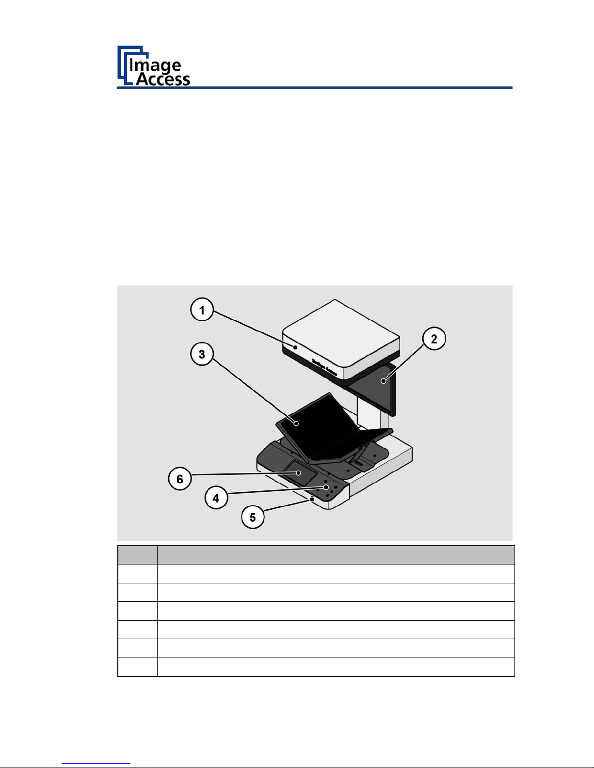
Bookeye® 4 V3 Overview
No.
Name
1
Camera head
2
TFT flat screen
3
V-shaped book cradle
4
Front panel
5
USB port
6
7" WVGA touchscreen
Page 14
Description
14
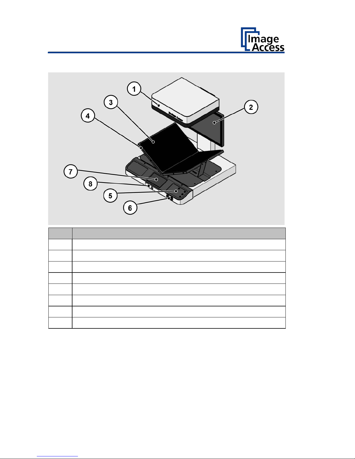
Bookeye® 4 V2 Overview
No.
Name
1
Camera head
2
TFT flat screen
3
V-shaped book cradle
4
Four additional start buttons
5
Front panel
6
Two USB ports
7
7" WVGA touchscreen
8
Pad holder (V2 Kiosk only)
Page 15

Description
15
Bookeye® 4 V2 Archive Overview
No.
Name
1
V-shaped glass plate which is manually lifted and lowered
Page 16
Description
16
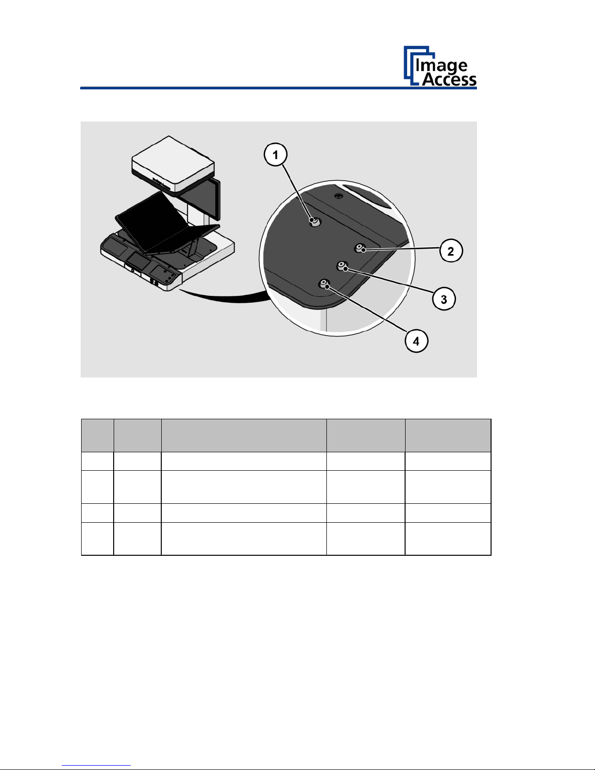
Keyboard Buttons
The key board of a Bookeye® 4 has, depending on the scanner model, two
or more buttons with additional functions.
No.
Name
Function
Bookeye 4
V3
Bookeye 4 V2
Kiosk/Archive
1
Power
Power on/off
X
X
2
Start
Displays the ScanWizard job
dialog
X
3
Scan
Starts a scan
X
X
4
Send
Displays the ScanWizard
output dialog
X
-
Page 17
Description
17
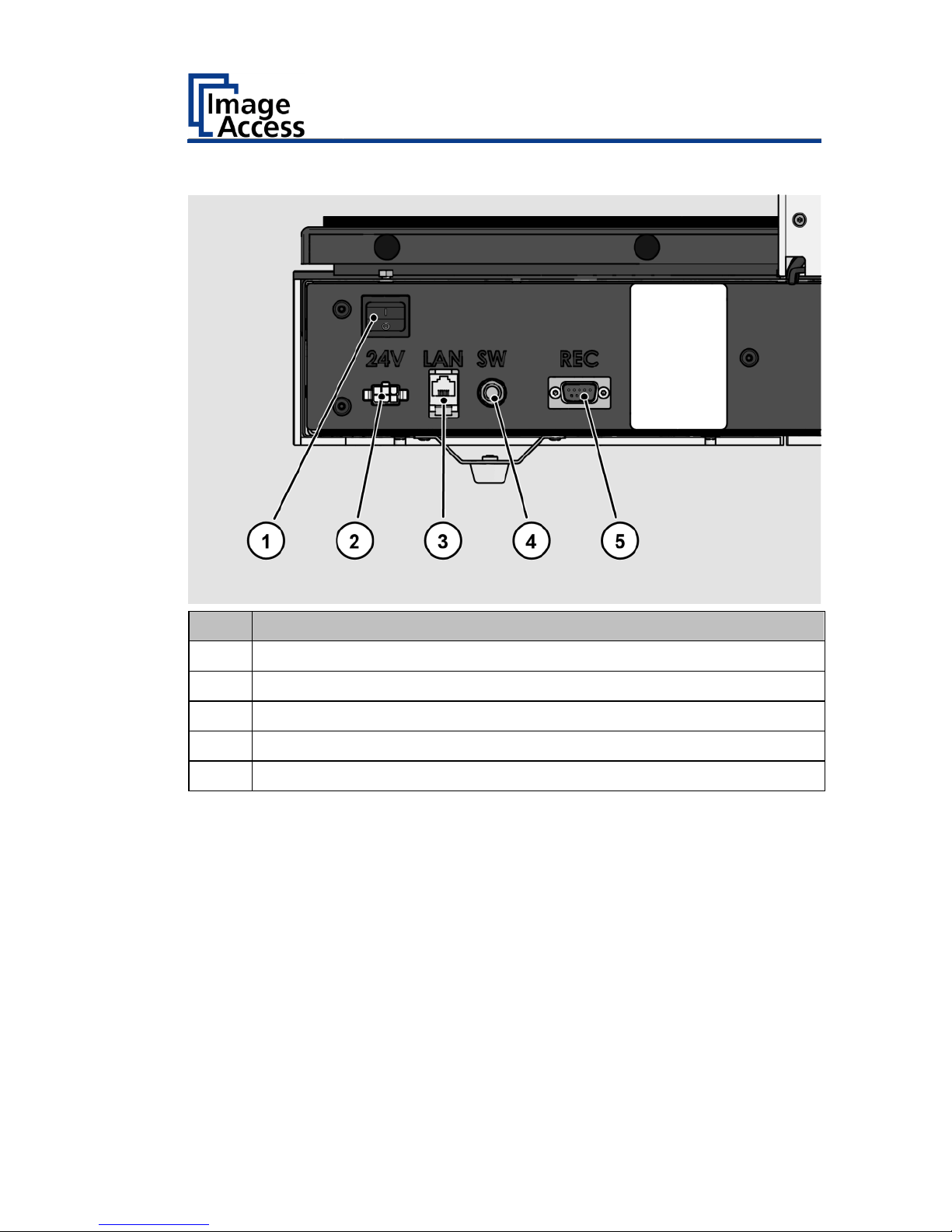
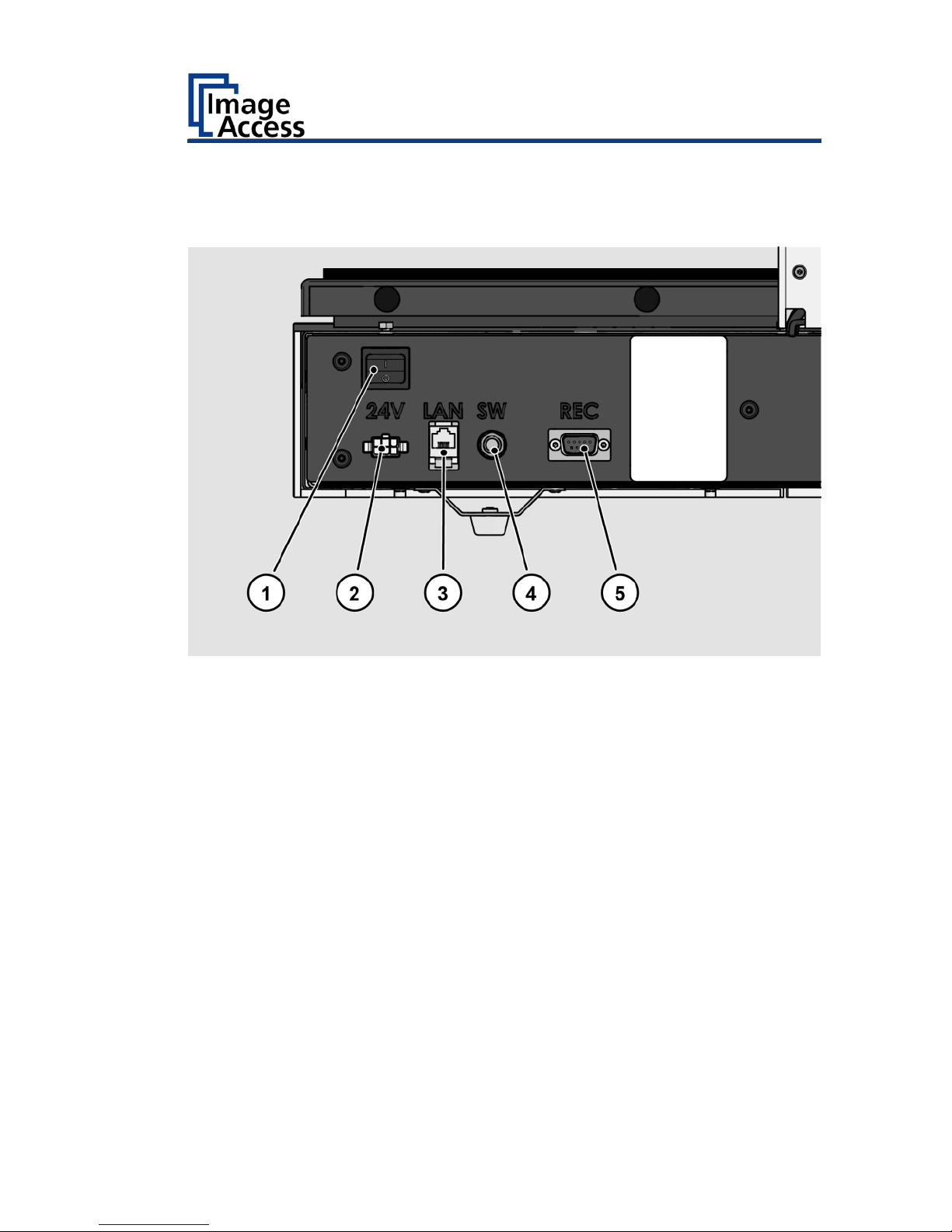
Rear View
No.
Name
1
Main switch
2
24 Vdc connector for external power supply
3
Network connector
4
Foot switch connector
5
Recovery key connector
Page 18

Description
18
Bookeye® 4 V1A Overview
No.
Name
1
Camera head
2
TFT flat screen
3
Glass plate
4
V-shaped book cradle
5
Front panel
6
Two USB ports
7
7" WVGA Touchscreen
Page 19
Description
19
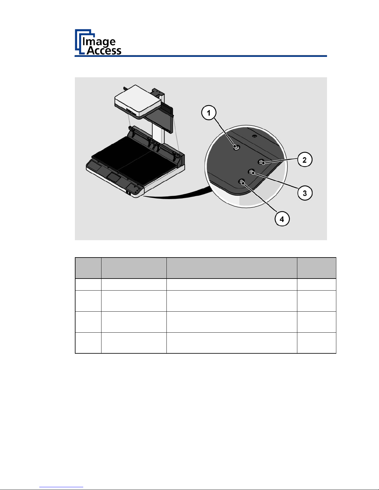
Keyboard Buttons
The key board buttons of a Bookeye® 4 1A.
No.
Name
Function
Bookeye
4 V1A
1
Power
Power on/off
X
2
Cradle Up
Drives the book cradle up
(Bookeye4 V1A only)
X
3
Cradle Down
Drives the book cradle down
(Bookeye4 V1A only)
X
4
Cradle Lock
Lock/unlock the scanner glassplate
(Bookeye4 V1A only)
X
Page 20
Description
20
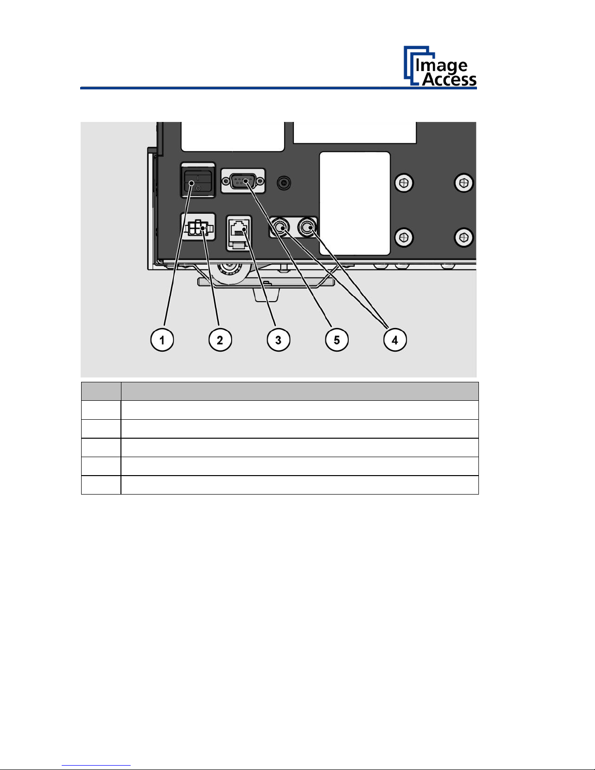
Rear View
No.
Name
1
Main switch
2
24 Vdc connector for external power supply
3
Network connector
4
Foot switch connectors
5
Recovery key connector
Page 21

Description
21
Setup Menu Overview Screen
No.
Name
1
Buttons and parameters
2
Menu name
3
Display the online help1
4
Button to exit the setup menu and return to the start screen
5
Serial number
6
IP address
7
Firmware version
1
The display of the online help is only available when a second
touchscreen is connected to the scanner.
Page 22

Description
22
Rating Plate
The rating plate is attached to the back of the scanner.
The following figure shows the Bookeye® 4 V3 rating plate.
The following figure shows the Bookeye® 4 V2 rating plate.
Page 23

Description
23
The following figure shows the Bookeye® 4 V1A rating plate.
Page 24
Device Location
24
Device Location
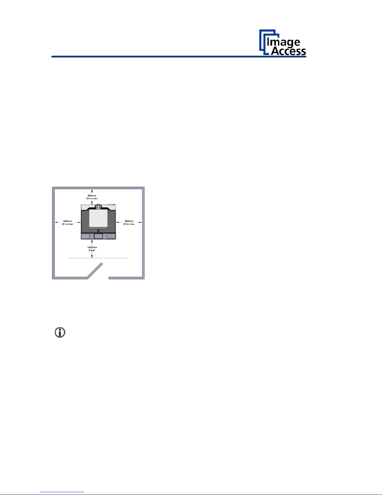
Environment
Choose a location that complies with the temperature and humidity
specifications.
Please allow
• a minimum distance of 500 mm (20 inches) from any side walls,
• a minimum distance of 500 mm (20 inches) from a back wall,
• a minimum distance of one meter (3 feet) from any door or entrance
way.
Place the Bookeye® 4 scanner on a flat and solid base. The load bearing
capacity of the base must correspond to the device weight. The
dimensions of the base must match the floor space required by the
scanner.
Before using the Bookeye® 4 scanner in the new environment allow at
least one hour for temperature adaptation.
A fast change from cold to warm environmental conditions can build up
condensation inside the housing.
This will result in unfavorable scanned images and could cause permanent
damages to the unit.
Page 25

Device Location
25
The Bookeye® 4 location should have a controlled ambient light
situation.
The light scenarios should avoid direct sunlight or spot light from light
beams.
Also, light sources that cause sharp shadows on the document on the
book cradles or high levels of ambient light could influence the scan
result negative.
The Bookeye® 4 scanner is an open system with a built-in high quality light
source. Open system means that the ambient light is added to the light
seen by the camera.
Summary of a recommended location for a Bookeye® 4 scanner:
• The location is not exposed to daylight.
• It is evenly illuminated from the ceiling with fluorescent lamps with
electronic ballasts. The light intensity measured on the book cradles
should be approximately 300 lux.
• The light should not cause any shadows; therefore, the variation of the
intensity across the scan area should be kept below 20%.
If the fluorescent lamps are powered by nonelectronic ballasts, they will
produce a flicker twice the frequency of the main power supply (100Hz or
120Hz). If the intensity of this light becomes too high, vertical stripes of
even distances of approx. 8-12 pixels will be visible on the scan.
Direct sunlight will vary over the day and will result in overexposed images.
Sunlight can also produce distinct shadows.
Light beams from spotlights will also produce distinct shadows. In most
cases, they emit a high level of infrared light. Infrared light is not visible to
the human eye but to the camera. The light source of the Bookeye® 4
scanner itself has no infrared content at all, which means that the scanner
does not have an image quality degrading infrared filter. Too much
infrared content will result in overexposure.
The Bookeye® 4 scanner has an integrated “White Balance” function. This
function will compensate ambient light influences. A “White Balance”
calibration is recommended when the light scenario has changed.
Page 26
Prepare for Setup
26
Prepare for Setup
Connect the Power Supply
WARNING
Risk of electric shock due to incorrect connection.
➢ Ensure that the power receptacle intended for the
connection is properly grounded.
➢ Ensure that the power receptacle intended for the
connection of the scanner is properly fused.
CAUTION
Incorrect laying of the connection cables can cause tripping.
Fractures, contusions and bruises can be the result.
➢ Place the connecting cables so that no one can trip over
them.
To connect the power supply, proceed as follows:
➢ Make sure that the main switch of the scanner is switched off (0
position).
➢ Use only the AC adapter and power cord supplied.
➢ Ensure the power cord is not damaged.
➢ Connect the connector from the power supply to the associated 24 Vdc
connector on the back of the scanner.
➢ If not already done, connect the supplied power cable to the associated
connector on the power supply.
➢ Connect the power plug of the power supply to a power receptacle of
the correct voltage (100-240 Vac).
Establish the Network Connection
CAUTION
Incorrect laying of the connection cables can cause tripping.
Fractures, contusions and bruises can be the result.
➢ Place the connecting cables so that no one can trip over
them.
Page 27

Prepare for Setup
27
To establish the network connection, proceed as follows:
➢ Connect one plug of the enclosed network cable to the network
connector socket on the back of the scanner.
➢ Connect the second plug to the network socket of an existing network.
Connect the Optional Foot Switch
➢ Connect the plug of the foot switch to the connector socket for the foot
switch, located on the back of the scanner.
Page 28
Prepare for Setup
28
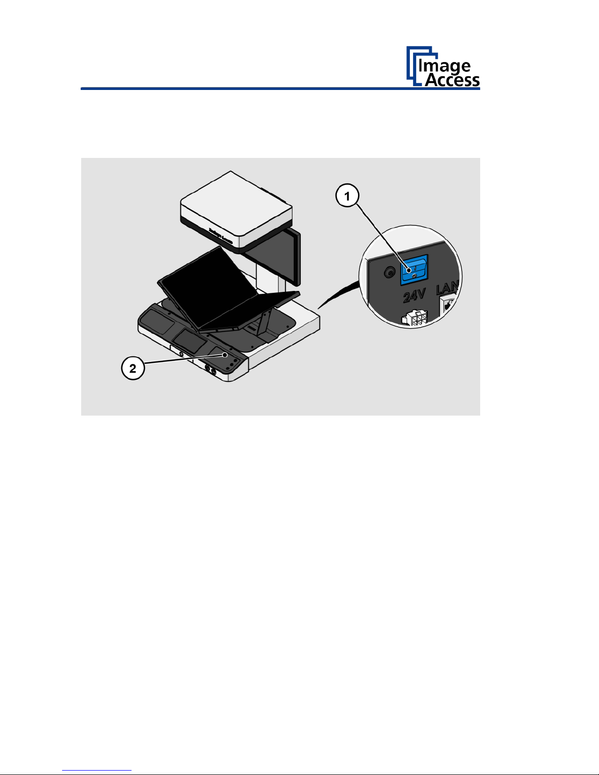
Switch On the Scanner
To switch on the scanner, proceed as follows:
➢ Press the MAIN SWITCH (1) on the back to the "I" position.
The power button (2) lights up in red.
➢ Press the power button.
The power button lights up in blue.
The scanner performs a system test. After a short wait, the start screen is
displayed.
To start the scanner from standby mode, proceed as follows:
➢ Press the red illuminated power button.
The power button lights up in blue.
The scanner performs a system test.
Page 29
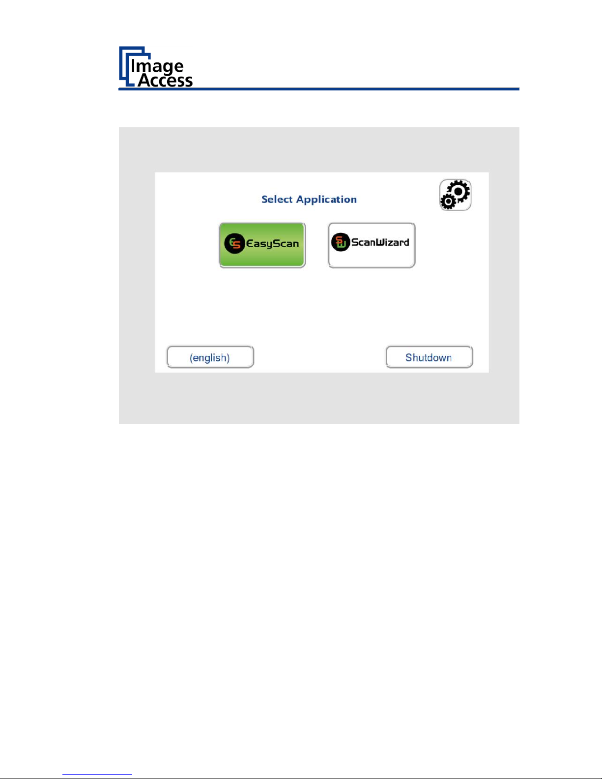
Prepare for Setup
29
After a short wait, the "Start screen" is displayed in English.
Page 30
Prepare for Setup
30
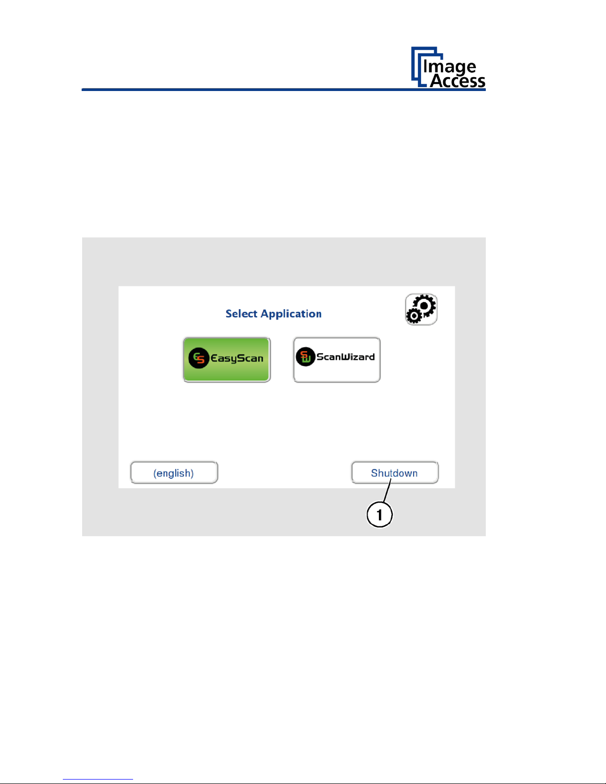
Switch Off the Scanner
To switch the scanner to standby mode after performing the setup,
proceed as follows:
➢ On the "Start screen" screen tap on SHUTDOWN (1).
➢ Confirm with YES.
The scanner shuts down. This process can take up to 40 seconds.
The power button lights up in red. The scanner is in standby mode.
Alternatively, switch the scanner into the standby mode as follows:
➢ Press the blue illuminated power button and hold it for six seconds.
The scanner shuts down. This process can take up to 40 seconds.
The power button lights up red. The scanner is in standby mode.
Page 31
Prepare for Setup
31
To switch off the scanner for longer periods, proceed as follows:
➢ Make sure that the scanner is in standby mode.
➢ Press the MAIN SWITCH (1) in the "0" position.
Page 32

Perform Setup
32
Perform Setup
Change the Menu Language
To change the menu language, proceed as follows:
➢ Tap the LANGUAGE (1) button to see all available languages.
Page 33

Perform Setup
33
A window for selecting the language appears.
➢ To display more languages, slide the scroll bar (1) downward.
➢ Tap the desired language.
The window for selecting the language is closed. The "Start screen" is
displayed.
Page 34

Perform Setup
34
Activate the Setup Menu
To activate the setup menu, you must log in on the scanner. Proceed as
follows:
➢ Tap the GEAR SYMBOL (1).
Page 35

Perform Setup
35
The login window appears.
➢ In the login window, enter the login credentials.
➢ Tap on the "Username" input field.
The screen keyboard is displayed.
➢ Enter the word "Poweruser".
➢ Tap on the "Password" input field.
➢ Enter the word "Poweruser".
➢ Please note that the input is case sensitive in both entry fields.
Page 36

Perform Setup
36
➢ To complete the log in, press OK (1).
Page 37

Perform Setup
37
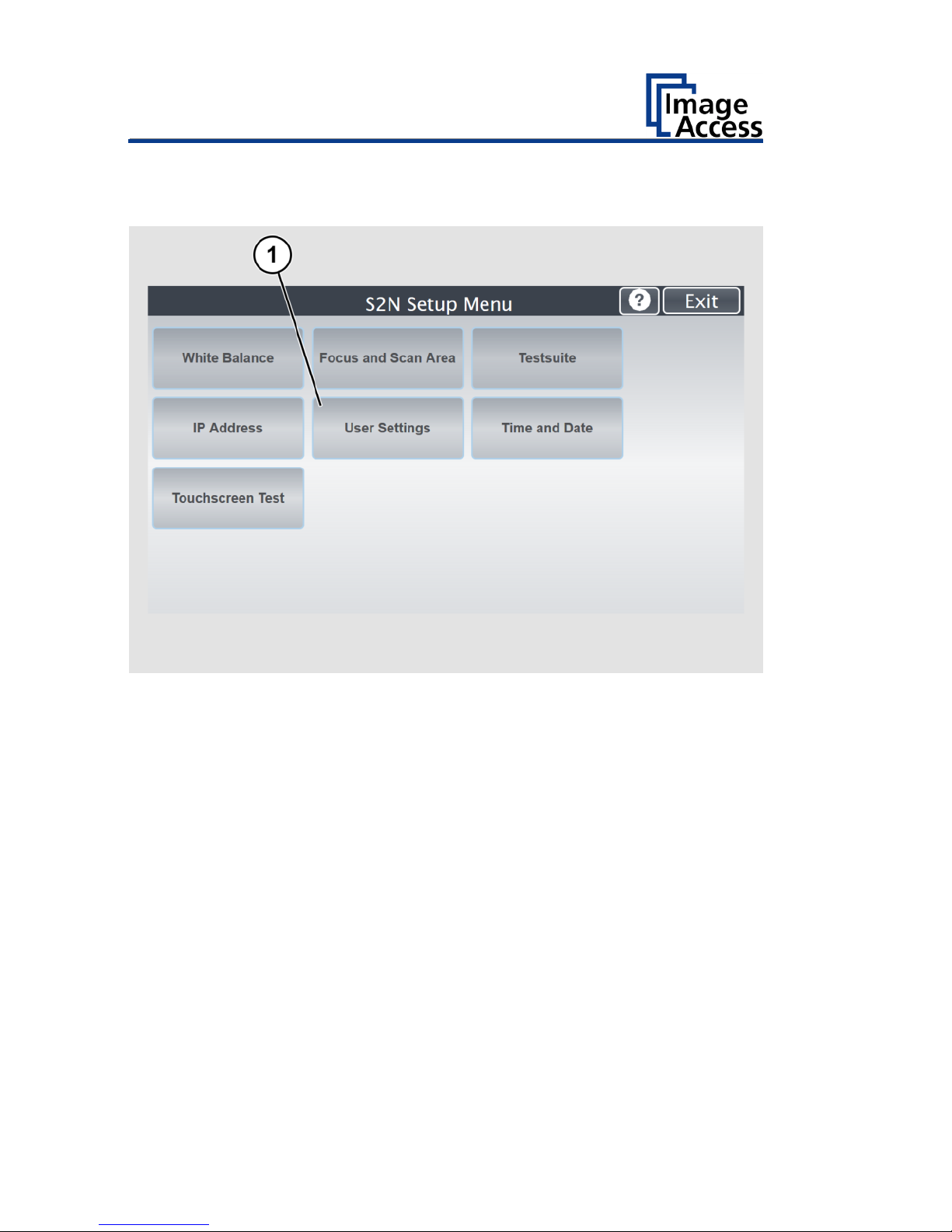
The "Setup Menu" screen is displayed.
White Balance:
Display the "White Balance" submenu
Focus and Scan
Area
Display the "Focus and Scan Area" submenu
Testsuite:
Display the "Test Suite" submenu
IP Address:
Display the "IP Address" submenu
User Settings:
Display the "User Settings" submenu
Time and Date:
Display the "Time and Date" submenu
Touchscreen Test:
Display the "Touchscreen Test" submenu
➢ To select a submenu from the "S2N Setup menu" screen, tap with your
finger on the button of the screen.
Page 38

Perform Setup
38
Perform White Balance
➢ On the "Setup Menu" screen, tap on WHITE BALANCE (1).
Page 39

Perform Setup
39
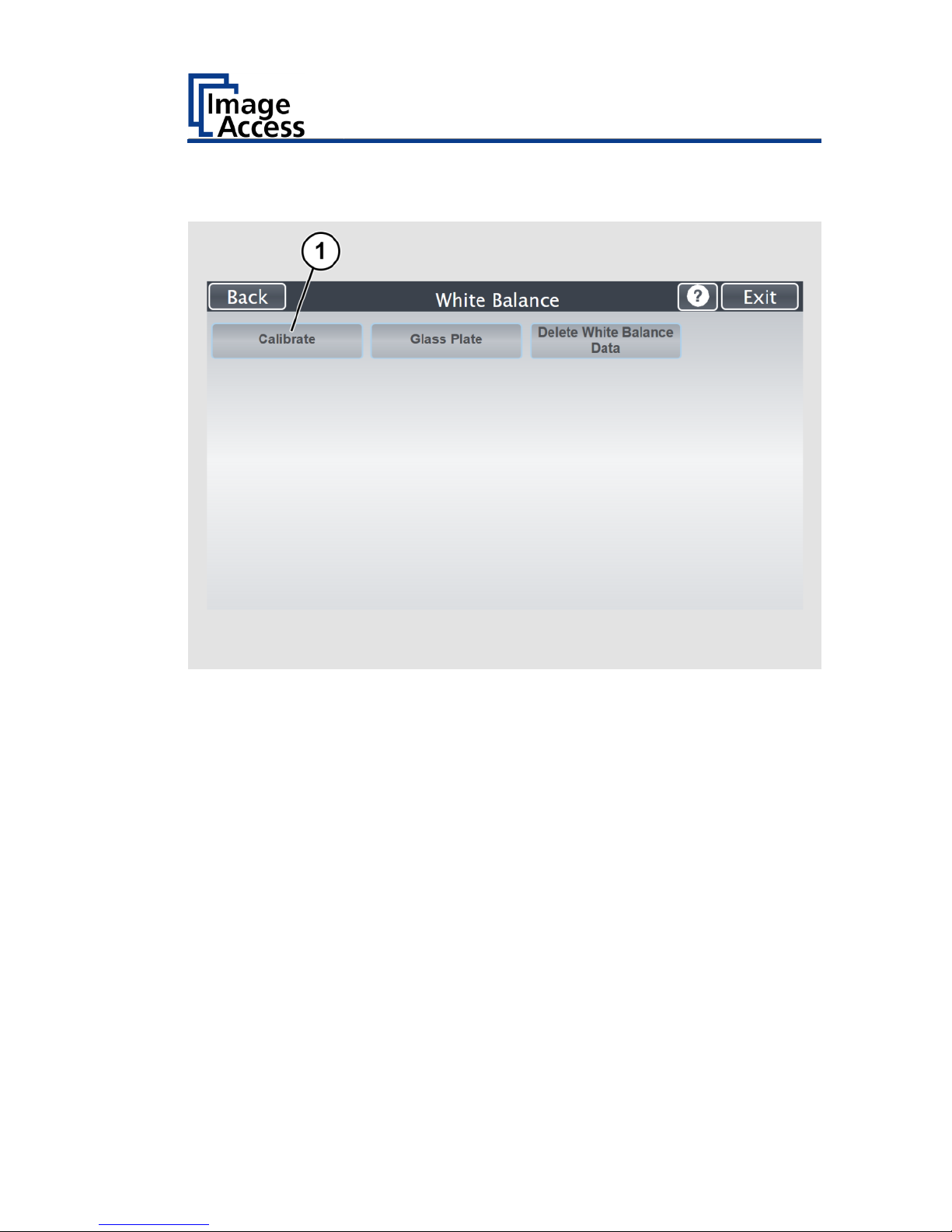
The "White Balance" screen is displayed.
Calibrate:
Start white balance
Glass Plate:
Start white balance with closed glass plate
Delete White
Balance Data:
Delete existing white balance data (not necessary
under normal operating conditions)
Page 40

Perform Setup
40
The white balance is used to ensure the quality of the scan results. The
white balance function is the most important function for consistent image
quality. This is especially important in the type of open scanning
environment present with overhead book scanners. During the white
balance measurement, all internal and external light sources are combined
and illuminate the target. The measurement results in a correction
function for the scan area.
The white balance will be carried out using a test target.
The test targets for book scanners are marked as follows:
• BE4-Z-V3-A
• BE4-Z-V2-A
• BE4-WA-V1-A
ATTENTION!
Impairment of the scan quality can occur if an improper
test target for the white balance is used.
➢ Make sure that the test target is free from wrinkles,
discolorations, cracks or other damage.
➢ Store the test target for the white balance in a safe place
protected from daylight.
Page 41
Perform Setup
41
To perform the white balance, proceed as follows:
➢ Tap on CALIBRATE (1).
Page 42

Perform Setup
42
➢ Position the supplied test target (1) onto the closed book cradles as
illustrated below (2).
The test target must overlap the upper and the lower margins of the book
cradle plate.
Page 43
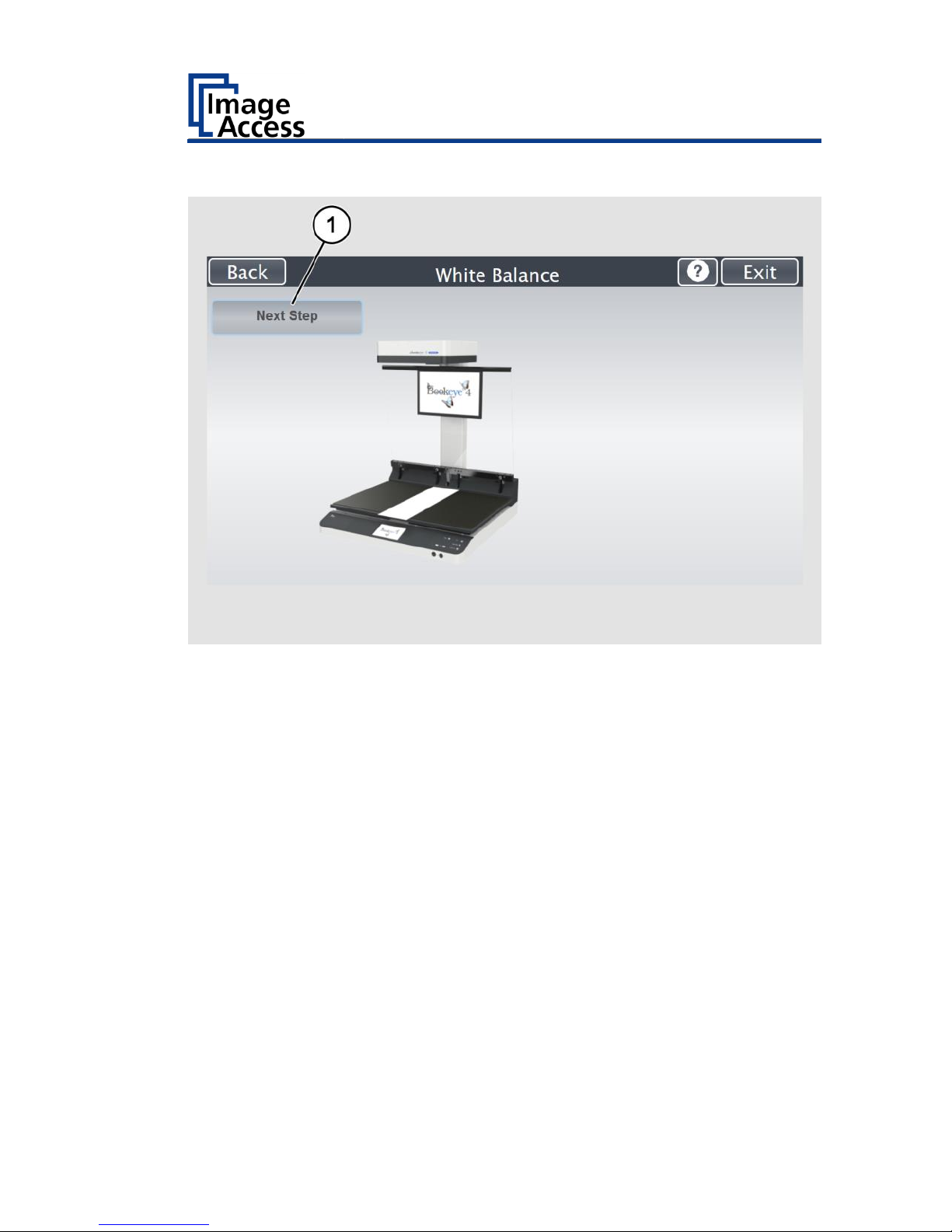
Perform Setup
43
➢ Tap on NEXT STEP (1).
The white balance starts and the calibration is performed. During the white
balance, a rotating icon appears. The entire white balance sequence takes
about 40 seconds.
Page 44

Perform Setup
44
Then, the white balance result is displayed as shown on the example
below.
On an error-free white balance calibration, the result is displayed in
green.
An incorrect result is displayed in red. If this is the case, repeat the
white balance calibration again.
Page 45

Perform Setup
45
➢ To perform the white balance again, tap NEW VALUES (2).
➢ To return to the previous submenu, tap BACK (1).
➢ To return to the "Start screen", tap EXIT (3).
➢ Tap BACK (1) to return to the previous submenu.
➢ To delete the stored data of the white balance calibration, tap DELETE
WHITE BALANCE DATA (2).
➢ After deleting the stored data, it is mandatory to run the white balance
again, as described.
➢ If problems arise during the white balance calibration, contact Image
Access technical support, see section Technical Support starting at page
8.
Page 46

Perform Setup
46
Perform White Balance - Glass Plate
➢ Tap on GLASS PLATE (1).
Page 47

Perform Setup
47
➢ Position the supplied test target onto the closed book cradles and under
the closed glass plate as illustrated below.
The test target must overlap the upper and the lower margins of the book
cradle plate and pressed firmly against the glass plate..
➢ Tap on NEXT STEP (1).
Page 48

Perform Setup
48
Then, the white balance result is displayed as shown on the example
below.
➢ To delete the stored data of the white balance calibration, tap DELETE
WHITE BALANCE DATA (Only if a white balance is not possible or if it
gives incorrect results).
➢ After deleting the stored data, it is mandatory to run the white balance
again, as described.
➢ If problems arise during the white balance calibration, contact Image
Access technical support, see section Technical Support starting at page
8.
After a successful white balance, proceed as follows:
➢ Remove the test target.
➢ Store the test target in a place which is protected from daylight.
➢ Ensure that the test target is not damaged, bent or soiled.
Page 49

Perform Setup
49
Calibrate Focus and Scan Area
➢ On the "S2N Setup Menu" screen tap on FOCUS and SCAN AREA (1).
Page 50

Perform Setup
50
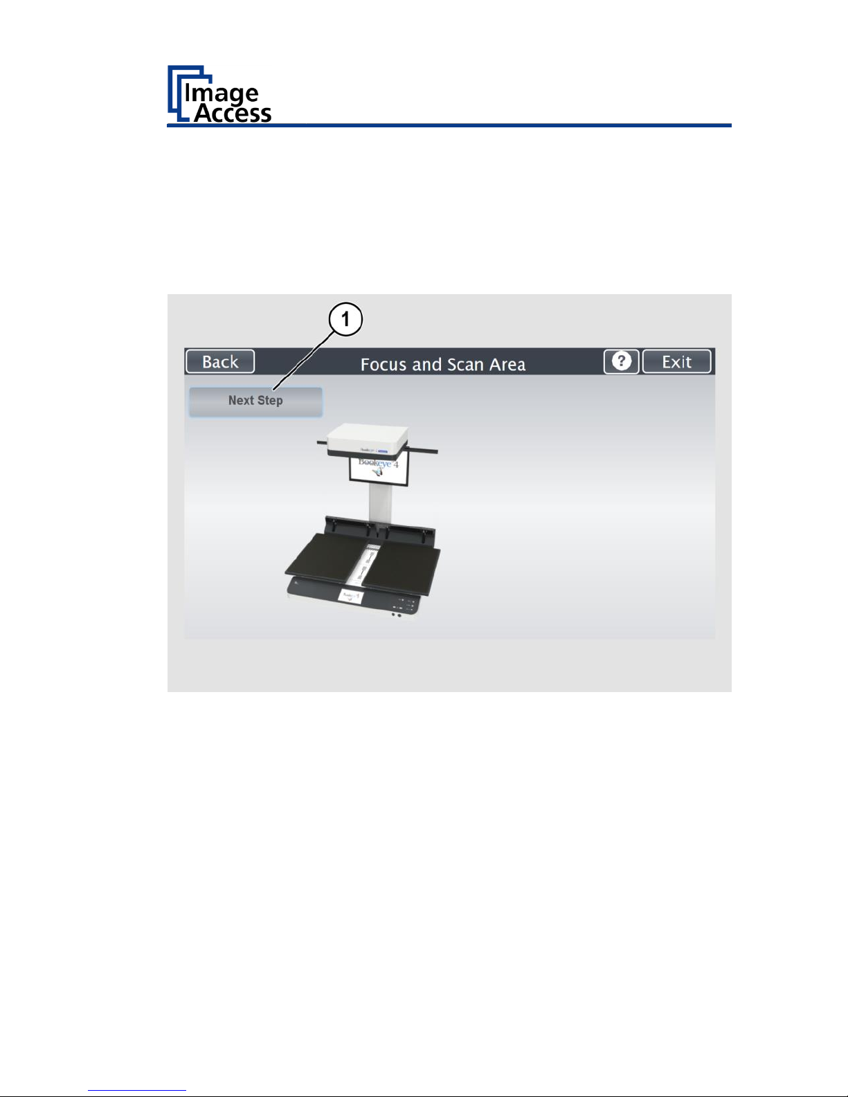
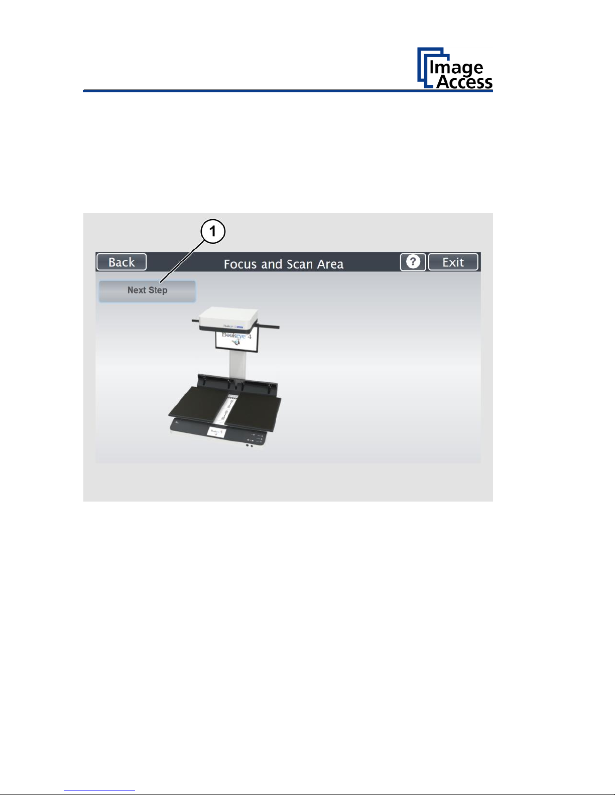
The "Focus and Scan Area" screen page appears.
Page 51

Perform Setup
51
Autofocus
This function automatically locates the lens position for the highest level of
sharpness and best image quality.
Tap on "AUTOFOCUS" (1).
Page 52

Perform Setup
52
For autofocus measurement, the book cradle plates must be opened as
shown on the touchscreen.
➢ Lift up the glass plate (if installed).
➢ Move the book cradle down and put it in flat position.
➢ Open the book cradles as displayed at the screen.
➢ Tap the NEXT STEP (1) button to start the measurement.
Page 53

Perform Setup
53
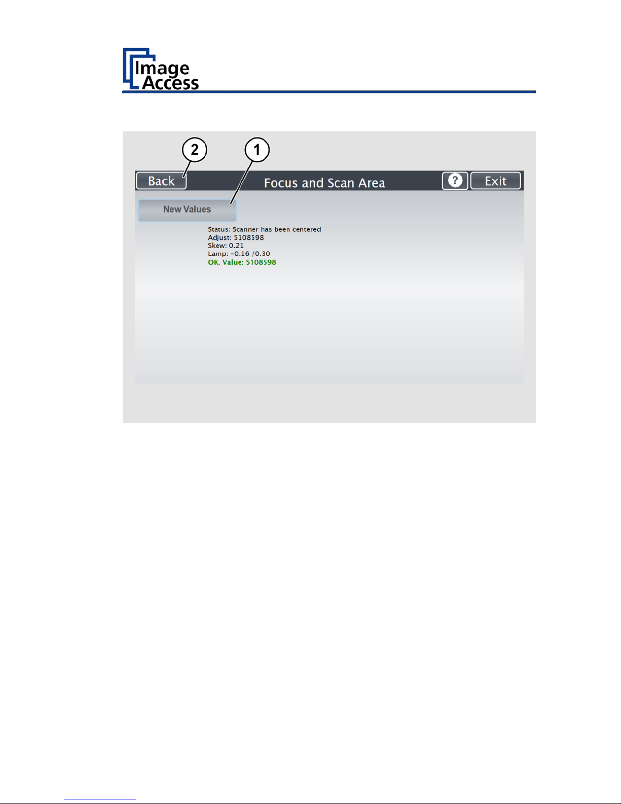
The result will be displayed.
Values displayed in green indicate valid results. Any error will be shown in
red text, followed by explanatory remarks.
If the values are not OK, repeat the measurement with a tap on the NEW
VALUES (1) button.
A variation of 50 – 100 in values when repeating the measurement is
within the parameters.
Tap the BACK (2) button to return to the Focus and Scan Area menu.
Page 54

Perform Setup
54
DPI Measurement
This function measures the resolution of the camera in relation to the
distance between scan area and camera.
➢ Tap on "DPI MEASUREMENT" (1).
Page 55
Perform Setup
55
For the DPI measurement, the book cradle plates must be opened as
shown on the touchscreen.
➢ Lift the glass plate up (if installed).
➢ Move the book cradle down and put it in the flat position.
➢ Open the book cradle as displayed on the screen.
➢ Tap the NEXT STEP (1) button to start the measurement.
Page 56

Perform Setup
56
The result will be displayed.
Values displayed in green indicate valid results. Any error will be shown in
red text, followed by explanatory remarks.
Repeat the measurement with a tap on the NEW VALUES (1) button.
It is normal that the measurement will return different values each time
the measurement is repeated.
Tap on BACK (2) button to return to the Focus and Scan Area menu.
Page 57

Perform Setup
57
Scan Start
This function synchronizes the position of the CCD camera and the lamps
position relative to each other.
The electronic gear is fine-tuned with this routine.
The measurement sequence will take a few moments.
➢ Tap on "SCAN START" (1).
Page 58
Perform Setup
58
For the scan start measurement, the book cradle plates must be opened as
shown on the touchscreen.
➢ Lift the glass plate up (if installed).
➢ Move the book cradle down and put it in the flat position.
➢ Open the book cradle as displayed at the screen.
➢ Tap the NEXT STEP (1) button to start the measurement.
The sound of the moving camera mirror is audible.
After a moment, both lamps light up, positioned in the horizontal middle of
the scan area.
The sound of the moving camera is audible again.
Finally, the light bar of each lamp moves over the scan area.
Page 59
Perform Setup
59
The result will be displayed.
Values displayed in green indicate valid results. Any error will be shown in
red text, followed by explanatory remarks.
If the values are not OK, repeat the measurement with a tap on the NEW
VALUES (1) button.
It is normal that the measurement will return different values each time
the measurement is repeated.
Tap the BACK (2) button to return to the Focus and Scan Area menu.
Page 60

Perform Setup
60
Laser Check
This function checks the integrity and position of the laser line.
The function will return skew and relative position to its ideal values and is
used to track potential misalignment.
The laser line is used by the camera electronics to measure the document’s
contour and to calculate the correction for the curvature of the document
binding.
➢ Tab on "LASER CHECK" (1).
Page 61

Perform Setup
61
For the laser check measurement, the book cradle plates must be closed as
shown on the touchscreen.
➢ Lift the glass plate up (if installed).
➢ Move the book cradle down and put it in the flat position.
➢ Close the book cradle as displayed on the screen.
➢ Place the Laser Check test target BE4-Z-V2-A or BE4-Z-V1-A as displayed
at the screen.
➢ In the middle of each long side, the test target has a marking.
➢ Place the test target on the book cradles so that the vertical laser line
covers these markings.
➢ Tap the NEXT STEP (1) button to start the measurement.
While the test sequence runs, the lamps will not light up.
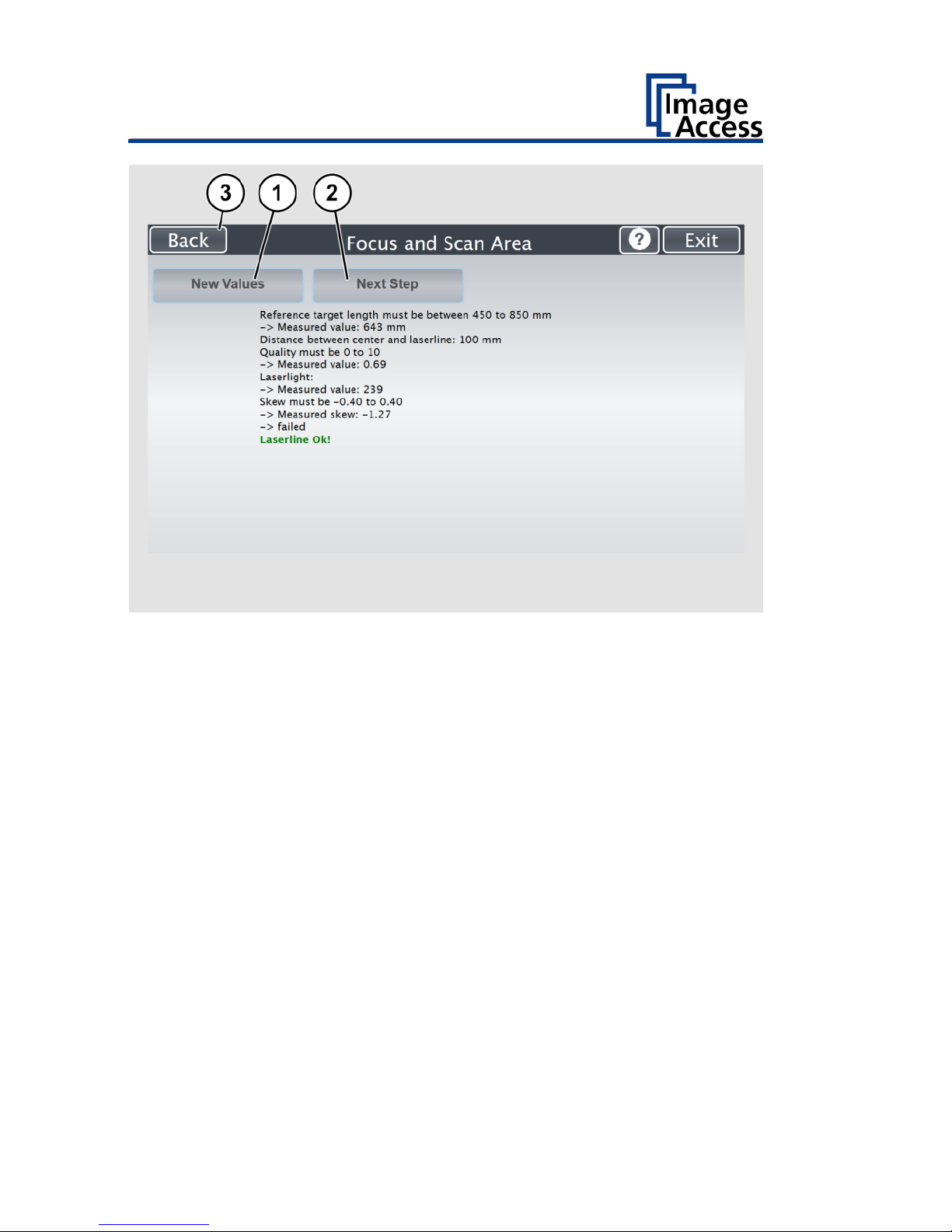
The result will be displayed.
Page 62
Perform Setup
62
Values displayed in green indicate valid results. Any error will be shown in
red text, followed by explanatory remarks.
If the values are not OK, repeat the measurement with a tap on the NEW
VALUES (1) button.
It is normal that the measurement will return different values each time
the measurement is repeated.
➢ Tap the BACK (2) button to return to the Focus and Scan Area menu.
Page 63

Perform Setup
63
➢ Click on NEXT STEP (2) button to execute the measurement with the
book cradle in V-position.
This is an optional measurement and does not need to be executed every
time.
➢ Tap the NEXT STEP (1) button to start the measurement.
Page 64

Perform Setup
64
➢ Lift the glass plate up (if installed).
➢ Move the book cradle down and put it in the flat position.
➢ Close the book cradle as displayed on the screen.
➢ Set the book cradles in the V-position.
➢ Place two CSTT targets (back sides) as displayed on the screen.
While the test sequence runs, the lamps will not light up.
Page 65

Perform Setup
65
The result will be displayed.
Values displayed in green indicate valid results. Any error will be shown in
red text, followed by explanatory remarks.
If the values are not OK, repeat the measurement with a tap on the NEW
VALUES (1) button.
It is normal that the measurement will return different values each time
the measurement is repeated.
➢ Tap the BACK (2) button to return to the Focus and Scan Area menu.
Page 66

Perform Setup
66
Gear Correction
This function performs a fine adjustment of the synchronization between
the lamps and the camera
➢ Tab the GEAR CORRECTION button (1).
Page 67

Perform Setup
67
For the gear correction measurement, the book cradle must be opened as
shown on the touchscreen.
➢ Lift up the glass plate (if installed).
➢ Move the book cradle down and put it in flat position.
➢ Open the book cradle as displayed at the screen.
➢ Tap the NEXT STEP (1) button to start the measurement.
The lamps light up and move over the scan area.
Page 68

Perform Setup
68
The result will be displayed.
Values displayed in green indicate valid results. Any error will be shown in
red text, followed by explanatory remarks.
If the values are OK, repeat the measurement with a tap on the NEW
VALUES (1) button.
It is normal that the measurement will return different values each time
the measurement is repeated.
Tap the BACK (2) button to return to the Focus and Scan Area menu.
Page 69

Perform Setup
69
Assign the IP Address
Manually Assign the IP Address
To manually assign the IP address, proceed as follows:
➢ On the "Setup Menu" screen, tap on IP Address (1).
Page 70
Perform Setup
70
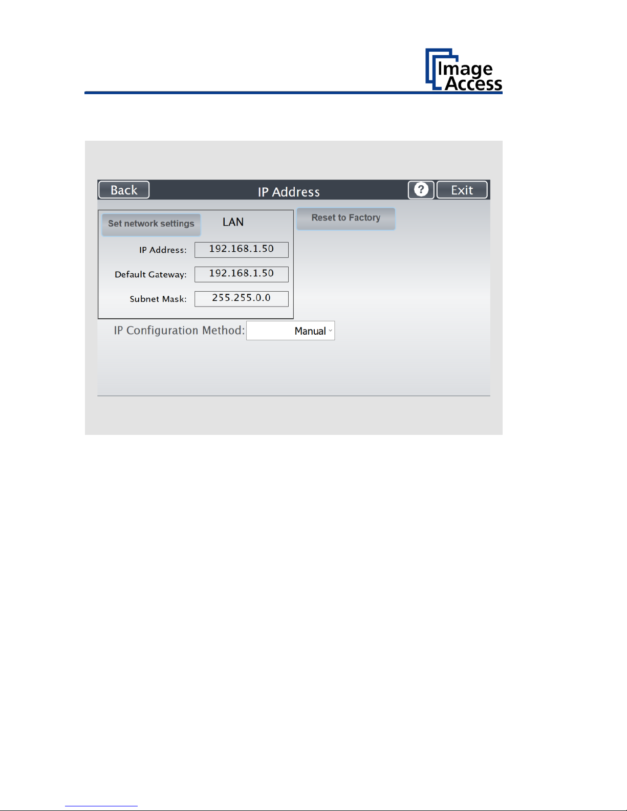
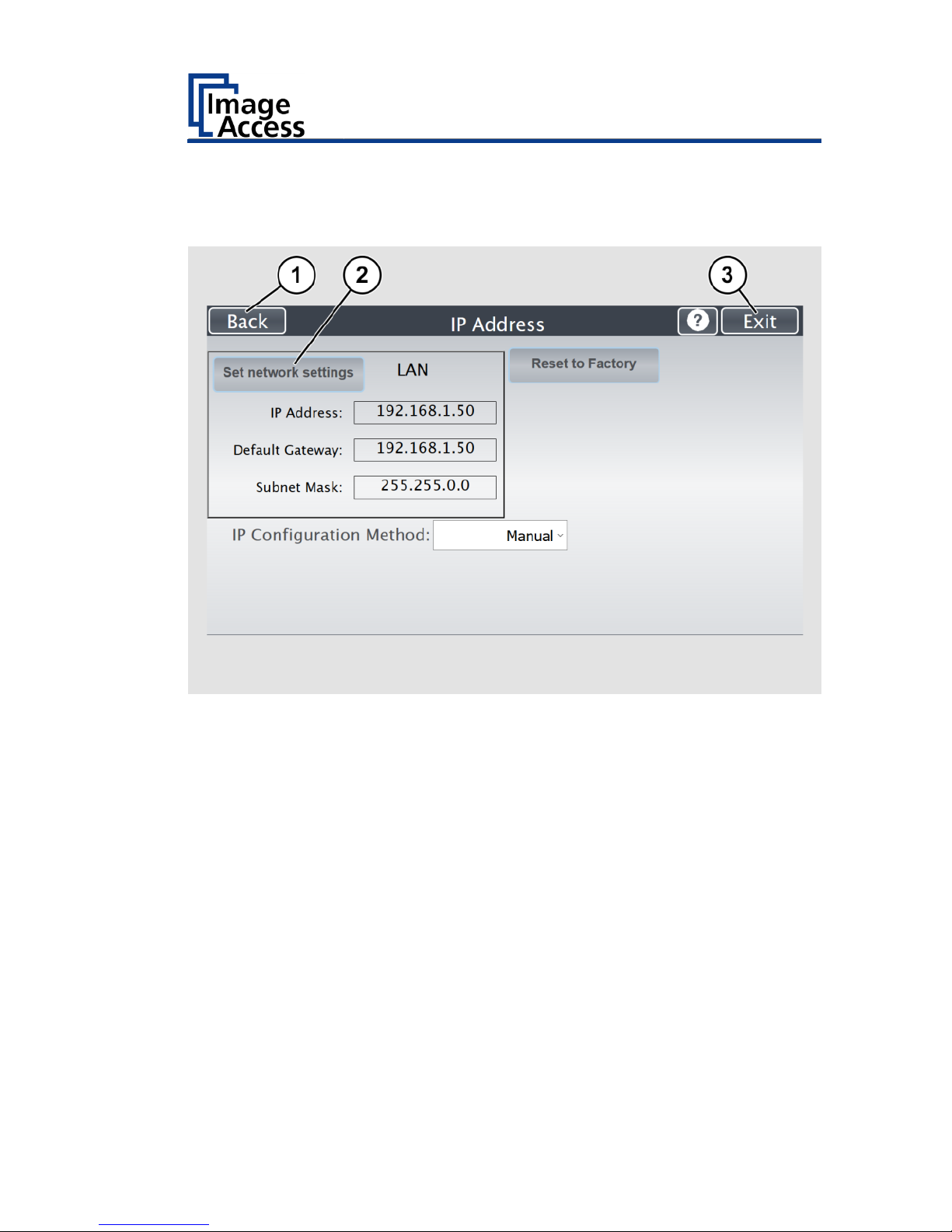
The "IP Address" screen is displayed.
Set network
settings:
Accept the network settings provided
Reset to Factory:
Reset to factory settings
IP Address:
Input field for the IP address
Default Gateway:
Input field for the gateway address
Subnet Mask:
Input field for data on the subnet mask
IP Configuration
Method
Manual/DHCP:
Assign an IP address manually or automatically
Page 71

Perform Setup
71
➢ Tap the "IP Address" (1) field.
Page 72

Perform Setup
72
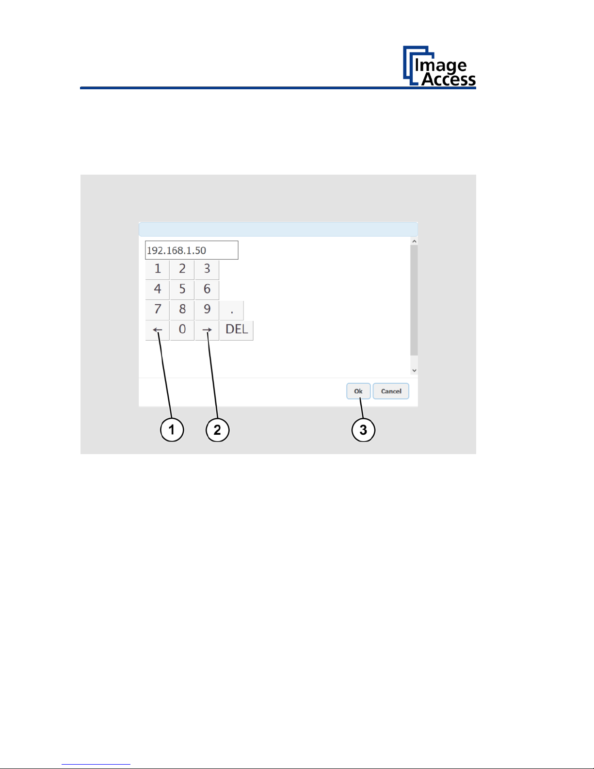
The "IP Address" window is displayed.
➢ Enter the IP address (1).
Page 73

Perform Setup
73
➢ To delete a digit, move the cursor to the right, behind the digit to be
deleted and tap DEL (1).
Page 74
Perform Setup
74
The arrow keys left (1) and right (2) next to the number "0" move the
cursor within the chosen row.
➢ To complete the entry, press OK (3).
➢ Perform the settings for gateway and subnet mask in the same way.
Page 75
Perform Setup
75
➢ To save the network settings, tap SET NETWORK SETTINGS (2).
➢ To return to the previous submenu, tap BACK (1).
➢ To return to the "Start screen", tap EXIT (3).
Page 76

Perform Setup
76
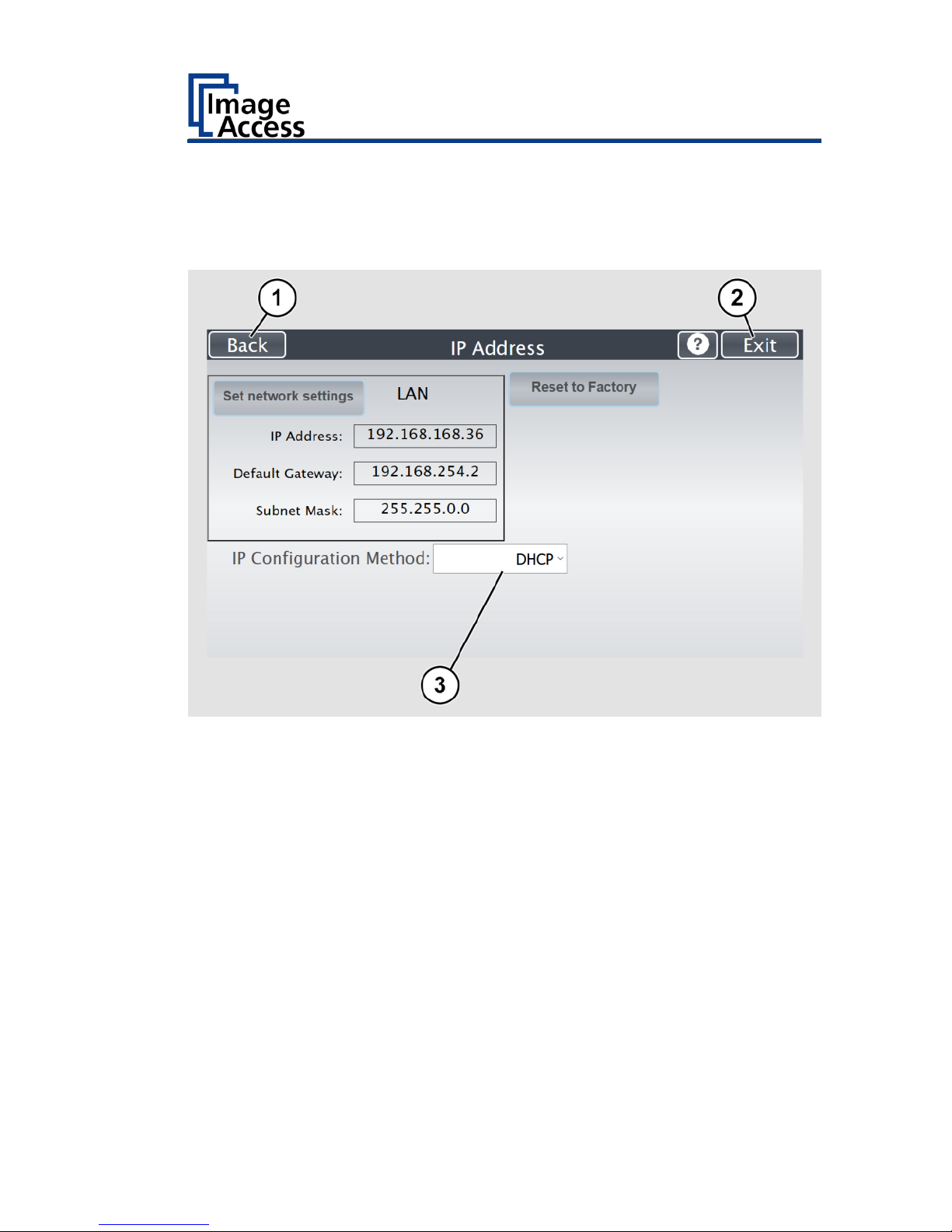
Automatically Assign the IP Address
To automatically assign the IP address, proceed as follows:
➢ On the setup menu screen, press the button IP ADDRESS (1).
Page 77
Perform Setup
77
➢ In the selection menu "IP Configuration Method", select the "DHCP" (3)
entry.
➢ To return to the previous submenu, tap BACK (1).
➢ To return to the "Start screen", tap EXIT (2).
Page 78
Perform Setup
78
Modify User Settings
➢ On the "Setup Menu" screen, tap on USER SETTINGS (1).
Page 79

Perform Setup
79
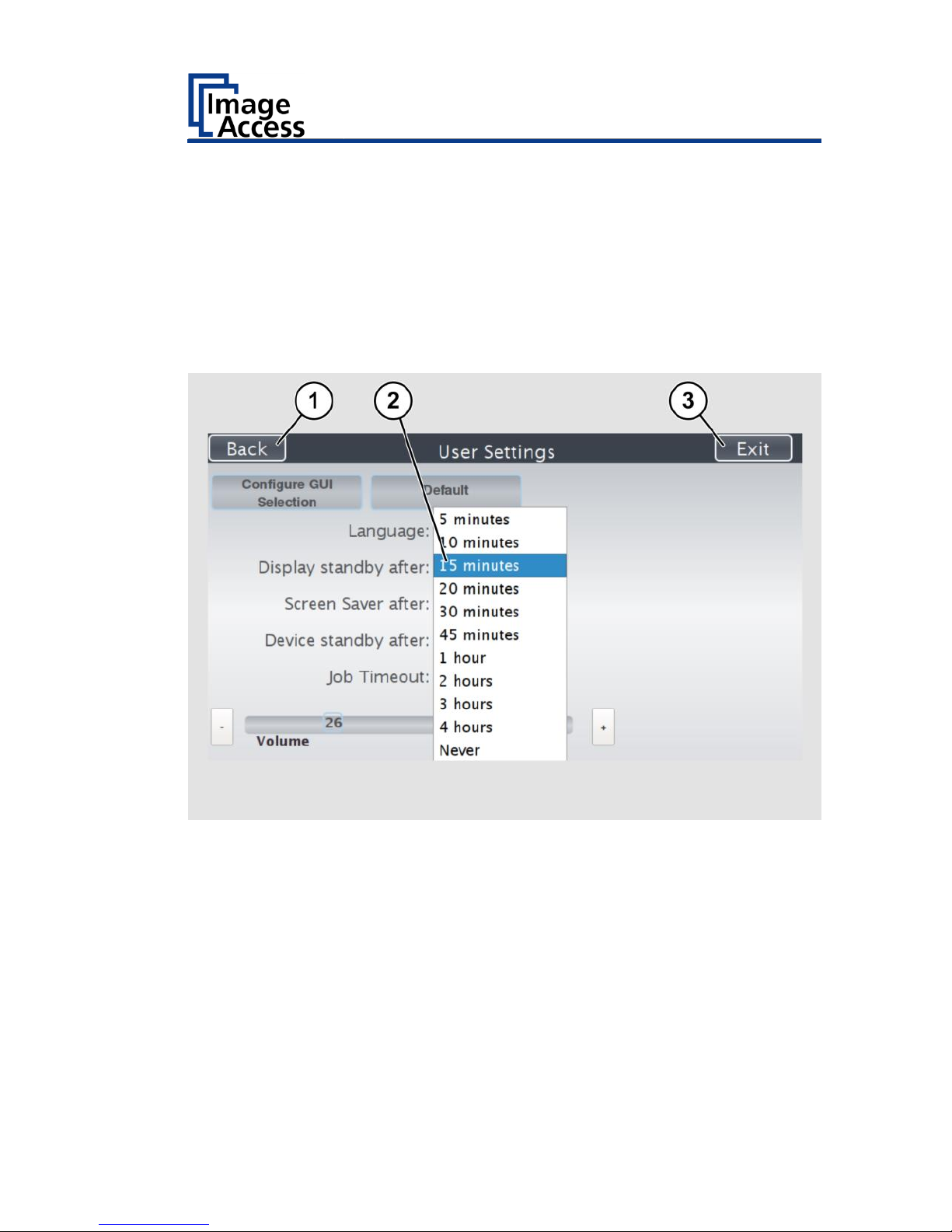
The "User Settings" screen is displayed.
Configure GUI
Selection:
Open the submenu for setting the application in
the start screen
Default:
The scanner will be reset to the default settings
Language:
Select language
Display standby
after:
Define the period of inactivity, until an optional
external monitor and the touchscreen switch to
the standby mode
Screen Saver after:
The period of inactivity until the screen saver is
activated is defined
Device standby
after:
The period of inactivity until the scanner goes into
standby mode is defined
Job Timeout
The period of inactivity until the scan job will be
terminated is defined.
Page 80

Perform Setup
80
Select Language
To select the language, proceed as follows:
➢ Tap the on the selection arrow of the selection menu "Language" to
display the list of languages.
➢ Tap the desired language (2).
➢ To return to the previous submenu, tap BACK (1).
➢ To return to the "Start screen", tap EXIT (3).
Page 81
Perform Setup
81
Set Standby Times
To set the standby times, proceed as follows:
➢ Tap the selection arrow of the selection menu.
➢ Tap on the desired entry (2).
➢ Perform the settings for the screen saver and the device standby in the
same way.
➢ To return to the previous submenu, tap BACK (1).
➢ To return to the "Start screen", tap EXIT (3).
Page 82

Perform Setup
82
Configuring the GUI Selection
➢ Tap the "User Settings" screen on CONFIGURE GUI SELECTION (1).
Page 83

Perform Setup
83
The "Configure GUI Selection" screen is displayed.
This menu displays the "EasyScan" and "ScanWizard" applications, which
are available as a standard selection. If you want to display only one of the
applications after system start, proceed as follows:
➢ Under "Displays" (1) disable the box corresponding to the application
you do not want to display.
Page 84

Perform Setup
84
By default, single mode is defined (activate the checkbox "Single mode
enabled").
➢ To start the application in job mode, uncheck the checkbox "Single
mode enabled" (2).
➢ To return to the previous submenu, tap BACK (1).
➢ To return to the "Start screen", tap EXIT (3).
Page 85

Perform Setup
85
Set the Time and Date
➢ On the "Setup Menu" screen, tap on TIME and DATE (1).
Page 86

Perform Setup
86
The screen "Time and Date" appears.
Enter new time:
Enter hours and minutes with the arrow keys
Enter new date:
Open a calendar to set the date
Store time and
date:
Accept the set values
Time Zone:
Select a time zone
Page 87

Perform Setup
87
To set the time, proceed as follows:
➢ Tap the "Enter new time" field.
➢ To set the time later, tap the up arrow (2).
➢ To set the time earlier, tap the down arrow (2).
➢ To save the modified time, click STORE TIME AND DATE (3).
➢ To return to the previous submenu, tap BACK (1).
➢ To return to the "Start screen", tap EXIT (4).
Page 88

Perform Setup
88
To set the date, proceed as follows:
➢ Tap the "Enter new date" field.
A calendar (3) is displayed.
➢ Select the appropriate date in the calendar (3).
➢ To set the month and year, tap the arrow keys (2, 4) at the top of the
calendar.
➢ To set the day, tap the corresponding day in the calendar.
➢ To save the date, click STORE TIME AND DATE (5).
➢ To return to the previous submenu, tap BACK (1).
➢ To return to the "Start screen", tap EXIT (6).
Page 89

Perform Setup
89
➢ To select the time zone, tap the selection arrow (4).
A selection list with available time zones is displayed.
➢ Select the appropriate time zone.
➢ To save the time zone, click STORE TIME AND DATE (2).
➢ To return to the previous submenu, tap BACK (1).
➢ To return to the "Start screen", tap EXIT (3).
Page 90

Perform Setup
90
Perform Test Suite
➢ On the "Setup Menu" screen, tap on TESTSUITE (1).
Page 91
Perform Setup
91
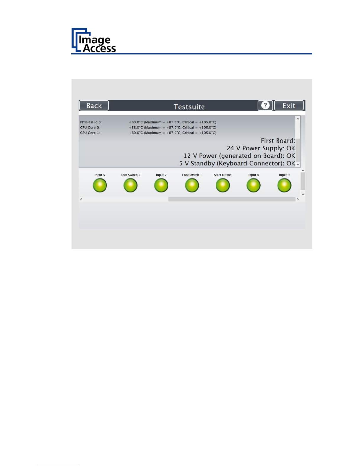
The "Testsuite" screen is displayed.
Information about
the mainboard:
Display the current values for:
Temperature of PCB and CPU cores, fan speed,
PCB voltages
Information about
the inputs:
Inputs will always appear green
Information on end
position switches,
foot switch and
power button:
When the end position switches, the foot switch
or the power button is pressed, the display
changes from green to red, for as long as the
switch or the button is pressed
Information about
LED lamps:
Check function: Lamp off, on, top, bottom, default
Page 92

Perform Setup
92
Perform Touchscreen Test
To check the functionality of the touchscreen when touched, proceed as
follows:
➢ On the "Setup Menu" screen tap the TOUCHSCREEN TEST (1) button.
Page 93

Perform Setup
93
The "Touchscreen Test" screen is displayed.
➢ To perform the "Touchscreen Test" tap with your finger on the
corresponding screen (3).
The crosshairs must occupy the same position as the finger.
➢ To end the "Touchscreen Test", tap the STOP TOUCHSCREEN TEST (1)
button.
➢ Tap the START EVENT TEST (2) button.
The "Event Test" screen is displayed.
The X button (3) cancels the test and returns to the start screen
"Touchscreen Test".
Page 94

Perform Setup
94
➢ Hold the upper left blinking green rectangle (1) with your finger.
➢ Swipe your finger from top left to top right over the touchscreen.
Page 95

Perform Setup
95
Green rectangles are drawn step by step.
These rectangles mark the area where the "Event Test" has detected the
motion events.
➢ As soon as you arrive at the top right, move down one line and then
move to the left again.
➢ Continue with this procedure until you have reached the lower right
edge of the screen.
This test can be aborted at any time by pressing the X (1) button.
If the entire screen is green, the test ends automatically.
The start screen of the "Touchscreen Test" appears.
The "Start screen" is displayed.
Page 96

Book Cradles - Bookeye4 V3/V2
96
Book Cradles - Bookeye4 V3/V2
The Bookeye® 4 V3/V2 scanner has a book cradle which can be operated in
two modes.
The plates of the book cradle can be shifted horizontally apart from each
other. This allows placing documents with a large spine in a position more
beneficial for the book spine. The maximum distance between the book
cradle plates is 85 mm (3.3 inch).
The plates can also be set to the “V” position, with an opening angle of 120
degrees. This is recommended for very delicate, old books and documents.
The plates are held in position by a supporting leg on each side.
Page 97

Book Cradles - Bookeye4 V3/V2
97
Additional Start Buttons - Bookeye4 V2
When operating the scanner using the WVGA color touchscreen or using
an external application, the scan sequence can be started by pushing one
of the four green start buttons.
For Bookeye® 4 V2 models only to easily operate the scanner while holding
the document in the flat position, each book cradle plate is equipped with
two start buttons on the front side.
Page 98

Book Cradles - Bookeye4 V1A
98
Book Cradles - Bookeye4 V1A
The Bookeye® 4 V1A scanner has a motorized book cradle which can be
operated in two modes.
Either in flat position
or in V position.
The V position is recommended for very delicate, old books and
documents. The opening angle between the book cradle plates is 140
degrees.
When the book cradles are lifted to the “V” position, they are held by a
supporting leg on each side.
In the “V” position, the plates can also be shifted horizontally apart from
each other.
Page 99

Operating the motorized book cradle - Bookeye4 V1A
99
Operating the motorized book cradle Bookeye4 V1A
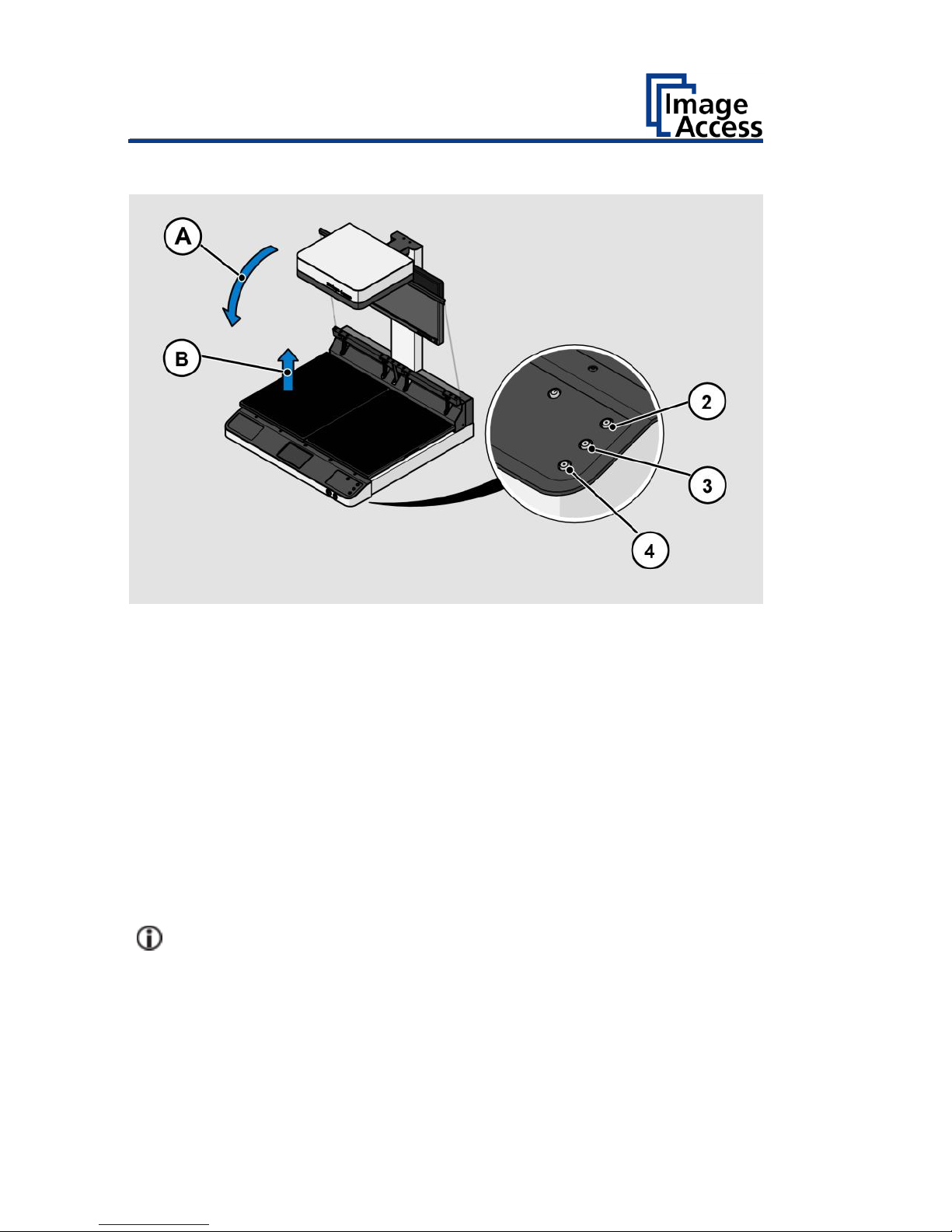
The Cradle Lock Button
The automatic locking of the glass plate in the lowered state is switched on
or off with the Cradle Lock button (4).
The button`s illumination color indicates the mode.
Illumination
Function
Off:
If the button light is off, the
magnetic lock function is turned off
Blue:
If the button light is blue, the
magnetic lock function of the glass
plate is activated.
Red:
If the button light is red, the
magnetic lock is engaged and the
glass plate is held in the closed
position. If the “Automatic mode" is
selected, the scan sequence starts
automatically.
Page 100
Operating the motorized book cradle - Bookeye4 V1A
100
The Cradle Up / Cradle Down Buttons
To move the book cradle to the desired position, press and hold the
• Cradle Up button (2) to lift the book cradle plates,
• Cradle Down button (3) to lower the book cradle plates.
Depending on the weight of the document placed on the book cradle, e.g.
book or catalogue, lifting of the book cradle plates should be started on
the side with the lighter load.
While moving the book cradle plates, the illumination in the respective
buttons changes from blue to red.
When the button is released the illumination returns to blue.
When both book cradle plates have been lifted completely, the motor
stops.
If there is no weight on the cradles, the operator must press down the
cradle plates manually while holding the Cradle Down (3) to get them
down completely.
 Loading...