

Page 1

Operation Manual
Page 2

File:
BE4-V1A_OperationManual_B5.docx
Page 3

Printed in Germany. All rights reserved.
Reproduction in whole or in part in any form or medium without express written permission of
Ima
Scan2Net
All other trademarks are the property of their respective o
Image Access reserves the right to change the described products, the specifications or
documents at any time without prior notice.
For the most recent version, always check our web site
or
www.imageaccess.us
2013 – 2014 by Image Access GmbH, Wuppertal, Germany.
ge Access is prohibited.
®
Operation Manual Page 3
, WideTEK® and Bookeye® are registered trademarks of Image Access.
or the customer service portal at portal.imageaccess.de
wners.
www.imageaccess.de
Page 4

Introduction
Dear Customer
We congratulate you on the acquisition of this innovative product from Image Access.
At Image Access, we are proud of the work we do; our products are the result of our
extremely high production standards and stringent quality control.
With the Bookeye® 4, Image Access offers an efficient V-cradle book scanner which
covers a wide range of applications due to its vers atility. The integrated web based user
interface enables access to all functions via a structured set of menus.
This operation manual is designed to lead you through the most typical situations
experienced when operating the Bookeye
®
4 scanner.
For this reason, we ask you to read the operation manual attentively before starting to
work with the device. By doing so, you will avoid operat ion errors and you can control all
functions effectively from the beginning.
In addition, please consider the following points:
• Damages to your unit may have occurred during shipping. Please check for
damages immediately after delivery of the unit. Inform your supplier if damage has
occurred.
• Read and ensure that you understand the safety notes. They were developed for
your protection and safety as well as to protect the unit.
®
• Regular maintenance conserves the high quality and safety of the Bookeye
4
scanner during the entire service life.
If you have any further questions, please feel free to contact your local dealer or
Image Access, Inc. directly. Our staff will be happy to help you.
®
For your daily work with the Bookeye
4, we wish you success and complete satisfaction.
Regards
Your Image Access Team
Page 4 Operation Manual
Page 5

About this Manual
Operation Manual
The Operation Manual provides all necessary information pertaining to the normal
operation and behavior of the device. It is written f or people who only operate the device
and do not perform setup and adjustment procedures. All device elements and software
functions are described in detail, although some of them might never be used. This
manual does not cover any application software. Refer to the appropr iate manual to learn
about the application software.
Setup Manual
The Setup Manual is written for technical staff with some basic mechanical skills and
software knowledge. Many resellers will offer on-site installation; ther efore, large parts or
all of the setup and assembly manual may not be of interest to the reader. The access
level at which the setup and adjustment procedures are performed is called “Power user”.
This “Power user” level is password protected from access by the normal operator.
All manuals can be downloaded from our customer service portal at
portal.imageaccess.de
. Be sure to always check for the latest versions of these manuals.
This manual is divided into sections.
Section A describes the hardware of the device and gives an overview of all
components and connectors of the scanner. Remember that this device is a
precise optical instrument and should be handled accordingly.
Section B describes the functions of t he touchscreen and how to operate the scanner
with the touchscreen.
Section C gives a short introduction and basic information about the new user
interface ScanWizard. All details about the interface can be found in the
integrated “Help” texts in the scanner.
Section D informs about the setup levels in general and describes the access level
User in detail.
Section E contains all technical information of the scanner and the manufacturer
declarations concerning safety and electromagnetic compatibility (EMC).
Operation Manual Page 5
Page 6

Version
Published in
Content/Changes/Supplements
March 2013
Preliminary version for Bookeye 4-V1A Professional.
July 2013
Preliminary version. Additional information about the glass plate
operation modes.
A
August 2013
First version.
B
November 2013
Section C: Content change because of introduction of the new
user interface ScanWizard.
added for chapters with safety relevant
content, with components des cription, and with description of the
language chapters marked with an “F” in the
Renumbering of some chapters as a result of the mentioned
amendments.
B3
March 2014
Copyright note updated.
Minor text modifications. Description of 45 degree position
modified.
B5
November 2014
Minor modifications in Technical Data table
Version History
B2 December 2013 French translations
first steps. Frenchchapter title.
B4 July 2014
Page 6 Operation Manual
Page 7

Table of Content
Introduction -------------------------------------------------------------------------- 4
About this Manual ----------------------------------------------------------------- 5
Version History --------------------------------------------------------------------- 6
A Hardware ----------------------------------------------------------------------- 16
A.1 Safety Notes ............................................................................................. 16
A.1.1 Marking of Safety Notes 16
A.1.2 Laser Safety Note 16
F-A.1 Notes de sécurité ...................................................................................... 17
F-A.1.1 Marquage des notes de sécurité 17
F-A.1.2 Marquage des notes de sécurité du laser 17
A.2 Safety Precautions .................................................................................... 18
F-A.2 Précautions de sécurité ............................................................................ 19
A.3 Certification ............................................................................................... 20
A.4 Device Location ........................................................................................ 21
A.4.1 Environment 21
A.4.2 Ambient Light 22
A.5 Content on Delivery .................................................................................. 23
A.6 Maintenance ............................................................................................. 23
A.6.1 Touchscreen 23
A.6.2 Surfaces 23
A.6.3 Book Cradles 23
A.7 Repair ....................................................................................................... 23
A.8 Device Overview ....................................................................................... 24
A.8.1 Connectors on the Rear Side 25
F-A.3 Aperçu du dispositif .................................................................................. 26
F-A.3.1 Connecteurs sur le côté arrière 27
A.9 Connecting the Power Source .................................................................. 28
F-A.4 Raccordement à l'alimentation électrique ................................................. 29
A.9.1 Starting the Bookeye® 4 30
A.9.2 Switching the Bookeye® 4 to Standby Mode 30
F-A.4.1 Mise en marche du Bookeye 4 31
F-A.4.2 Commutation du Bookeye 4 sur le mode de veille 31
Operation Manual Page 7
Page 8

Table of Content, part 2
A.10 Book Cradles ........................................................................................... 32
A.11 Glass Plate Functionality ......................................................................... 33
A.11.1 In General 33
A.11.2 Glass Plate Positions 33
A.11.2.1 Transport lock posi tion 33
A.11.2.2 Fully up position 34
A.11.2.3 The 45 degree angled position 35
A.12 Operating the motorized book cradle ....................................................... 36
A.12.1 The Cradle Lock Button 36
A.12.2 The Cradle Up / Cradle Down Buttons 36
A.13 Glass Plate Operating Modes .................................................................. 37
A.13.1 Setting the Operation Modes 37
A.13.2 Manual Mode 38
A.13.3 Automatic Mode 38
A.13.3.1 Manual adjustment of the height of the book cradle plates 38
A.13.4 Working with the Book Cradle Plates 39
A.14 The “Finger Removal” Function ............................................................... 42
A.14.1 Position of Document 42
A.14.2 Finger Positions 43
A.14.3 Wrong Finger Positions 44
A.14.3.1 Distance too small 44
A.14.3.2 Finger position too steep 44
A.14.3.3 Fingers hold too close to the margi n of the docum ent 45
A.14.4 Examples of Finger Removal 46
A.14.4.1 Book positioned at the book cradle 46
A.14.4.2 Single finger holds the book 46
A.14.4.3 Multiple fingers hold the book 49
A.14.4.4 Small books with pattern at margin 51
A.15 The “Splitting” Function ............................................................................ 52
A.15.1 “Splitting” function with two separate doc uments 52
A.15.2 “Splitting” function with a single document 53
A.15.3 “Splitting” function with single document at middle of the book cradle plates 54
A.15.4 “Splitting” function with a book 56
A.15.5 Document positions which can result in malfunction 57
A.15.5.1 Single pages 57
A.15.5.2 Books 57
Page 8 Operation Manual
Page 9

Table of Content, part 3
B Touchscreen Oper a t ion --------------------------------------------------- 58
B.1 Select Application Scr een ......................................................................... 58
B.2 Start Screen of the Kiosk User Interface ................................................... 59
B.2.1 Control Fields of the Touchscreen 60
B.3 Touchscreen – Document Source ............................................................ 61
B.3.1 Document Mode 62
B.3.1.1 Auto Mode 62
B.3.1.1.1 Document Position / Minimum Document Size 63
B.3.1.2 Book Mode 64
B.3.1.3 Flat Mode 64
B.3.1.4 V-Mode 64
B.3.1.5 Folder Mode 64
B.3.2 Resolution 65
B.3.3 Format 66
B.3.3.1 Maximum 67
B.3.3.2 Auto 68
B.3.3.2.1 Finger Removal Mode 69
B.3.3.3 Crop and Deskew 70
B.3.3.4 DIN 71
B.3.3.5 ANSI 72
B.3.4 Splitting Image 73
B.3.5 Scan Mode 74
B.3.6 Exposure 75
B.3.7 Auto Density [Binary] 76
B.4 Touchscreen – Image Q uali ty ................................................................... 77
B.4.1 Color Mode 78
B.4.2 File Format 78
B.4.2.1 JPEG 78
B.4.2.2 TIFF 79
B.4.2.3 PNM 79
B.4.2.4 PDF 79
B.4.3 Brightness 80
B.4.4 Contrast 80
B.4.5 Gamma 80
B.4.6 Image Sharpness 80
B.4.7 Image Rotation 81
B.4.8 Mirror 81
B.4.9 Invert 81
B.4.10 Despeckle 81
Operation Manual Page 9
Page 10

Table of Content, part 4
B.5 Touchscreen – Viewer & Job Control ....................................................... 82
B.5.1 Zonal OCR 84
B.5.2 Job Mode 87
B.5.2.1 Navigating through the list of images 89
B.5.2.2 Moving an image to another position 90
B.5.2.3 Adding an image at an any position to the list 90
B.5.2.4 Deleting an image from the list 90
B.5.2.5 Rescan an image 90
B.5.2.6 Finalizing the Job mode 91
B.5.2.6.1 Job mode time out 91
B.6 Touchscreen – Send To ........................................................................... 92
B.6.1 Changing a file name or other entries 93
B.6.2 USB Options 94
B.6.2.1 List of suitable USB storage media 94
B.6.3 Copy Options 95
B.6.3.1 Printer Settings 95
B.6.4 FTP Options 96
B.6.5 Network Options 97
B.6.6 Mail Options 98
B.6.6.1 Transaction modes 99
C The ScanWizard User Interface ---------------------------------------- 100
C.1 The ScanWizard User Interface ............................................................. 101
C.2 Information ............................................................................................. 103
Page 10 Operation Manual
Page 11

Table of Content, part 5
D The Setup Level ------------------------------------------------------------- 104
D.1 Access Level User .................................................................................. 105
D.1.1 Device Info 106
D.1.2 Operation Info 108
D.1.3 User Settings 109
D.1.3.1 Language Selector 110
D.1.3.2 Power Saving 111
D.1.3.3 Volume 112
D.1.3.4 Foot Pedal 113
D.1.3.5 Glass Plate 114
D.1.3.6 Splitting Start Page 115
E Technical Data --------------------------------------------------------------- 116
E.1 Scanner Specifications ........................................................................... 116
E.2 Electrical Specifications .......................................................................... 117
E.3 Dimensions and Weight .......................................................................... 118
E.4 Ambient Conditions ................................................................................. 118
E.5 CE Declaration of Conformity ................................................................. 119
E.6 FCC Declaration of Conform ity ............................................................... 121
Operation Manual Page 11
Page 12

Table of Pictures
Picture 1: Minimum distance between Bookeye and walls ............................................... 21
Picture 2: Elements of the Bookeye 4-V1A ...................................................................... 24
Picture 3: Connectors on the rear side ............................................................................ 25
Picture 4: Keyboard with Power button ............................................................................ 30
Picture 5: Book cradles in flat mode and closed .............................................................. 32
Picture 6: Book cradles in V mode and closed ................................................................. 32
Picture 7: Loosen the transport locks ............................................................................... 33
Picture 8: Transport locks opened ................................................................................... 33
Picture 9: Transport locks and rubber bumpers ............................................................... 34
Picture 10: Glass plate opened in 45 degree position ...................................................... 35
Picture 11: Setting the book cradle mode ........................................................................ 37
Picture 12: Manual operation ........................................................................................... 37
Picture 13: Automatic operation ....................................................................................... 37
Picture 14: Pushing one side lifts other side simultaneously ............................................ 38
Picture 15: Book cradle plates opened ............................................................................ 39
Picture 16: Book prepositioned at book cradle ................................................................. 39
Picture 17: Lowering the book cradle ............................................................................... 40
Picture 18: Glass plate closed ......................................................................................... 41
Picture 19: Book at book cradle in flat position ................................................................ 42
Picture 20: Book at book cradle opened in “V” position.................................................... 42
Picture 21: Correct finger position ................................................................................... 43
Picture 22: Minimum vertical distance ............................................................................. 43
Picture 23: Single pages on book cradle plates ............................................................... 52
Picture 24: Single document on book cradle plate ........................................................... 53
Picture 25: Document position on book cradle plates ...................................................... 54
Picture 26: Splitting result with Format = Crop and Deskew ............................................ 54
Picture 27: Splitting result with Format = Auto ................................................................. 55
Picture 28: Book cradle plates set to “V” position ............................................................. 56
Picture 29: Large book at book cradle in “V” position ....................................................... 56
Picture 30: Wrong position of book cradle and pages ...................................................... 57
Picture 31: Book in bad position for splitting .................................................................... 57
Picture 32: Start screen after start-up .............................................................................. 58
Picture 33: Viewer & Job Control screen ......................................................................... 59
Picture 34: Document Source screen .............................................................................. 61
Picture 35: List of Document Modes ................................................................................ 62
Page 12 Operation Manual
Page 13

Table of Pictures, part 2
Picture 36: Document placed correctly .............................................................................63
Picture 37: Document placed incorrectly ..........................................................................63
Picture 38: List of Resolutions ..........................................................................................65
Picture 39: Selector for Format settings ...........................................................................66
Picture 40: Parameters for Maximum format ....................................................................67
Picture 41: Book Mode Formats .......................................................................................68
Picture 42: Crop and Deskew screen ...............................................................................70
Picture 43: Format DIN (=ISO) selected ...........................................................................71
Picture 44: List of ANSI formats .......................................................................................72
Picture 45: Splitting Image ...............................................................................................73
Picture 46: Selecting the „Splitting Start Page“.................................................................73
Picture 47: Available Scan Modes....................................................................................74
Picture 48: Exposure Modes ............................................................................................75
Picture 49: Numeric key pad to set threshold value .........................................................75
Picture 50: Auto Density slider .........................................................................................76
Picture 51: Image Quality 1 ..............................................................................................77
Picture 52: Image Quality 2 ..............................................................................................77
Picture 53: List of Color Modes ........................................................................................78
Picture 54: Submenu File Format “jpeg”...........................................................................78
Picture 55: Submenu File Format TIFF ............................................................................79
Picture 56: Brightness slider ............................................................................................80
Picture 57: Contrast slider ................................................................................................80
Picture 58: Gamma slider ................................................................................................80
Picture 59: Image Sharpness ...........................................................................................80
Picture 60: Image Rotation...............................................................................................81
Picture 61: Mirror .............................................................................................................81
Picture 62: Invert ..............................................................................................................81
Picture 63: Despeckle ......................................................................................................81
Picture 64: Viewer & Job Control screen ..........................................................................82
Picture 65: Scanned image in preview area .....................................................................82
Picture 66: OCR button activated .....................................................................................84
Picture 67: OCR touchscreen ..........................................................................................84
Picture 68: Rectangle defines the area for OCR function .................................................85
Picture 69: Pre-selection area selected ............................................................................85
Picture 70: Selected area magnified ................................................................................86
Operation Manual Page 13
Page 14

Table of Pictures, part 3
Picture 71: OCR result..................................................................................................... 86
Picture 72: Bottom line with status ................................................................................... 87
Picture 73: TFT flat screen after selecting “Job mode”..................................................... 87
Picture 74: Disclaimer when staring the Job mode .......................................................... 88
Picture 75: Job mode start screen ................................................................................... 88
Picture 76: Controller circles blanked out ........................................................................ 89
Picture 77: Destination to finalize Job mode .................................................................... 91
Picture 78: Information when time out ends ..................................................................... 91
Picture 79: "Send To" screen #1 ...................................................................................... 92
Picture 80: "Send To" screen #2 ...................................................................................... 92
Picture 81: Alphanumeric keyboard ................................................................................. 93
Picture 82: Directory of connected USB data carrier ........................................................ 94
Picture 83: Parameters of Copy Options ......................................................................... 95
Picture 84: Printer settings window .................................................................................. 95
Picture 85: Parameters of FTP Options ........................................................................... 96
Picture 86: Parameters of Network Options ..................................................................... 97
Picture 87: Parameters of Mail Options ........................................................................... 98
Picture 88: Interactive mode, mail options ....................................................................... 99
Picture 89: Scan2Net® main menu ............................................................................... 100
Picture 90: ScanWizard interface .................................................................................. 101
Picture 91: ScanWizard interface layout ........................................................................ 101
Picture 92: Online Help.................................................................................................. 102
Picture 93: “Exit” returns to Scan2Net® main menu ...................................................... 102
Picture 94: Information .................................................................................................. 103
Picture 95: Login screen ................................................................................................ 104
Picture 96: User screen ................................................................................................. 105
Picture 97: Device Info screen ....................................................................................... 106
Picture 98: Firmware information ................................................................................... 107
Picture 99: Operation Info screen .................................................................................. 108
Picture 100: User Settings start screen ......................................................................... 109
Picture 101: Language Selector screen ......................................................................... 110
Picture 102: Power Saving ............................................................................................ 111
Picture 103: Volume level .............................................................................................. 112
Picture 104: Foot pedal settings .................................................................................... 113
Picture 105: Setting for automatic mode ........................................................................ 114
Picture 106: Splitting start page ..................................................................................... 115
Page 14 Operation Manual
Page 15

Operation Manual Page 15
Page 16

A Hardware
A.1 Safety Notes
Read and ensure that you understand the safety notes.
The safety notes have been written to ensure your protection and for your safety.
Follow all safety notes to avoid damage to the device.
A.1.1 Marking of Safety Notes
All safety notes are marked with a warning sign.
A description of the potential hazard is found at the right side beside the warning sign.
WARNING!
<Text with description of potential hazard.>
A.1.2 Laser Safety Note
CAUTION!
Laser Class 1
Certified acc. IEC 60825-1:2008-05
Do not stare into beam!
Page 16 Operation Manual
Page 17

F-A.1 Notes de sécurité
Lisez ces notes de sécurité et veillez à bien les comprendre.
Ces notes ont été rédigées pour assurer votre protection et votre sécurité.
Respectez toutes les notes de sécurité pour éviter d’endommager le dispositif.
F-A.1.1 Marquage des notes de sécurité
Toutes les notes de sécurité sont marquées par un panneau d’avertissement.
Vous trouverez une description du risque de sécurité à droite, à côté du panneau
d’avertissement.
MISE EN GARDE!
<Texte avec description du danger potentiel.>
F-A.1.2 Marquage des notes de sécurité du laser
ATTENTION!
Laser Classe 1
Certifié conformément à IEC 60825-1:2008-05
Ne regardez pas dans le faisceau !
Operation Manual Page 17
Page 18

this device to rain
A.2 Safety Precautions
Warning: Please read all the safety precautions before you operat e the scanner. Serious
injury can occur to you or to others if you do not know how to use it safely.
To prevent fire or shock hazard, do not expose
or any type of moisture.
Follow all safety precautions to avoid personal injury or damage to the device.
1. Openings in the scanner’s housing are provided for air circulation. Do not cover or
block the openings.
2. Do not place the scanner near a heat or cold emitt ing source such as a space heater,
furnace, or air conditioning unit.
3. Do not place the scanner near any devices or electrical boxes emitting high voltage.
4. Always place the scanner on a stable surface.
5. Do not place cups containing liquids or other such objects on the scanner or on the
book cradles. If liquid spills into the scanner it can cause damage. If this occurs, t urn
the scanner off, unplug the power cord from the wall receptacle and contact the
Image Access Technical Support.
6. Do not put any objects into any scanner housing openings unless specifically
instructed to do so by Image Access Technical Support.
7. Do not disassemble the scanner. If there is a need to disassemble the scanner,
please contact the Image Access Technical Support.
8. Do not use the scanner if it has been physically damaged. If this occurs, turn the
scanner off, unplug the power cord from the wall receptacle and contact the
Image Access Technical Support.
9. The scanner should be used only with the power supply that is delivered with the
scanner. If you are unsure, please contact the Image Access Technical Support.
10. Image Access recommends plugging the scanner into an appropriately-rated power
conditioner.
11. Always turn the power off and unplug the power cord from the wall receptacle before
cleaning the scanner.
12. When cleaning, do not use any type of solutions, abrasives, or acids such as acetone,
benzene, kerosene, mineral spirits, ammonia, or nitric acid. Do not use any cleaners
that contain these chemicals.
13. Do not spray any liquids directly onto the scanner. Spray cleaning fluids directly onto
the cleaning cloth and use the cloth to clean the scanner.
Page 18 Operation Manual
Page 19

F-A.2 Précautions de sécurité
Mise en garde: Veuillez lire toutes les précautions de sécurité avant de faire
fonctionner le scanner. Vous risquez de graves blessures, sur vousmêmes ou sur autrui, si vous ne savez pas comment vous en servir en
toute sécurité.
Pour éviter tout risque d’incendie ou de commotion, n’exposez pas
cet appareil à la pluie ou à une humidité quelconque.
Respectez toutes les notes de sécurité pour éviter de vous blesser ou d’endommager le
dispositif.
1. Des ouvertures sont pr atiquées dans le boîtier du scanner pour la circulati on de l’air.
Ne couvrez ou n’obstruez pas ces ouvertures.
2. Ne placez pas le scanner à proximité d’une source de chaleur ou de f roid telle qu’un
radiateur électrique portatif, un poêle ou un appareil de climatisation.
3. Ne le placez pas près d’appareils ou de boîtiers électriques émettant une haute
tension.
4. Posez toujours le scanner sur une surface stable.
5. Ne posez pas de tasses contenant des liquides ou d’autres objets similaires sur le
scanner ou sur les berceaux de livres. Si un liquide est répandu sur le scanner, il
risque de l’endommager. Si cela se produit, éteignez le scanner, débranchez le
cordon d’alimentation de la prise de courant murale et contactez l’Assistance
Technique de Image Access.
6. N'introduisez pas d'objets dans les ouvertures du boîtier du scanner, sauf si
l’Assistance Technique de Image Access vous en donne l’instruction.
7. Ne démontez pas le scanner. Si vous êtes oblig é de démonter le scanner, veuillez
contacter l’Assistance Technique de Image Access.
8. N’utilisez pas le scanner s’il a été endommagé physiquement. Si cela se produit,
éteignez le scanner, débranchez le cordon d’alimentation de la prise de courant
murale et contactez l’Assistance Technique de Image Access.
9. Le scanner devrait uniquement être utilisé avec l’alimentation électrique qui est
fournie avec le scanner. En cas de doute, veuillez contacter l’Assistance Technique
de Image Access.
10. Image Access recommande de brancher le scanner sur un climatiseur électrique
d’une puissance appropriée.
11. Coupez toujours l’alimentation électrique et débranchez le cordon d’alimentation de la
prise de courant murale avant de nettoyer le scanner.
12. Pour ce nettoyage, évitez d’utiliser des solutions, des abrasifs ou des acides
quelconques tels que l’acétone, le benzène, le kérosène, des alcools minéraux, de
l’ammoniac ou de l’acide nitrique. N’utilisez pas de nettoyants contenant ces produits
chimiques.
13. Ne pulvérisez pas de liquides directement sur le scanner. Pulvérisez les liquides de
pulvérisation directement sur le chiffon de nettoyage et utilisez-le pour nettoyer le
scanner.
Operation Manual Page 19
Page 20

A.3 Certification
All safety requirements of the following standards are fulfilled by the Bookeye® 4 scanner:
IEC 60950-1, International Safety Standard for Information Technology Equipment
UL 60950-1, Safety for Information Technology Equipment (US standard)
CAN/CSA C22.2 No.60950-1, Safety for Information Technology Equipment
(Standard of Canada)
EN 60950-1, Safety for Information Technology Equipment (European standard)
All approval marks of the above named tests can be found on the type label of the device.
Page 20 Operation Manual
Page 21

A.4 Device Location
A.4.1 Environment
Choose a location that complies with the temperature and humidity specifications. For
detailed information on these specifications, see the chapter E.4.
Please allow
• a minimum distance of 500 mm (20 inch) from any side walls,
• a minimum distance of 500 mm (20 inch) fr om a back wall,
• a minimum distance of one meter (3 feet) from any door or entrance way.
Picture 1: Minimum distance between Bookeye and walls
Do not operate the scanner in an area that has poor air circulation, and/or that is nonventilated.
®
Place the Bookeye
4 scanner on a flat and solid base. The load bearing capacity of the
base must correspond to the device weight.
The dimensions of the base must match with the floor space required by the scanner.
Please note: Before using the Bookeye
®
4 scanner in the new environment allow at least
one hour for temperature adaptation.
What does “temperature adaptation” means?
A fast change from cold to warm environmental conditions can build up
condensation inside the housing. This will result in unfavorable scanned
images and could cause permanent damages to the unit.
Operation Manual Page 21
Page 22

A.4.2 Ambient Light
The Bookeye® 4 location should have a controlled ambient light situation. The light
scenarios should avoid direct sunlight or spot light from light beams.
Also light sources that cause sharp shadows on the document on the book cradles or high
levels of ambient light could inf luence the scan result negative.
The Bookeye
system means that the ambient light is added to the light seen by the camera.
Summary of a recommended location for a Bookeye
• The location is not exposed to daylight.
• It is evenly illuminated from the ceiling with fluorescent lamps with electronic
ballasts. The light intensity measured on the book cradles should be approximately
300 lux.
• The light should not cause any shadows; therefore the variation of the intensity
across the scan area should be kept below 20%.
If the fluorescent lamps are powered by non-electronic ballasts, they will produce a flicker
twice the frequency of the main power supply (100Hz or 120Hz). If the intensity of this
light becomes too high, vertical stripes of even distances of approx. 8-12 pixels will be
visible on the scan.
®
4 scanner is an open system with a built-in high quality light source. Open
®
4 scanner:
Direct sunlight will vary over the day and will result in overexposed images. Sunlig ht can
also produce distinct shadows.
Light beams from spotlights will also produce distinct shadows. In most cases, they emit a
high level of infrared light. Infrared light is not visible to the human eye but to the camera.
The light source of the Bookeye
®
4 scanner itself has no infrared content at all, which
means that the scanner does not have an image quality degrading infrared filter. Too
much infrared content will result in overexposure.
The Bookeye
®
4 scanner has an integrated “White Balance” function. This function will
compensate ambient light influences. A “White Balance” calibration is recommended
when the light scenario has changed.
Page 22 Operation Manual
Page 23

A.5 Content on Delivery
The scanner is delivered in a wooden transport box. The transport box also contains
• A folder with four CSTT-2 reference targets
• Three White Reference targets BE4-WA-V1-A
• A foot pedal switch (optional)
• Patch cable, length 3 meters.
• Recovery Key with instructions
• External power supply with power cable
Please note: Keep the wooden transport box for future use! If the scanner needs to be
returned to depot, it must be sent back in the or iginal transport box to avoid
transport damages.
A.6 Maintenance
Important: Ensure that no liquids will penetrate into the device housing.
A.6.1 Touchscreen
The touchscreen can be cleaned with a micro fiber cloth.
®
Before cleaning the touchscreen, switch the Bookeye
power switch to position 0.
4 scanner off and set the main
A.6.2 Surfaces
Use a soft, dampened cloth to clean the housing of the scanner. Recommended is a micro
fiber cloth.
A.6.3 Book Cradles
Important: The rubber mats on the book cradles may only be cleaned dry!
Use a vacuum cleaner from time to time to clean the mats from dust and particles.
A.7 Repair
Please note: T here are not any parts or components of the Bookeye® 4 scanner which
can be repaired by the user.
All repairs and service works should be done by a trained technician only.
Operation Manual Page 23
Page 24

A.8 Device Overview
Picture 2: Elements of the Bookeye 4-V1A
Some of the major components of the Bookeye® 4 scanner have been identified in the
above picture. These components are referenced in this operation manual.
The Bookeye
®
4 scanner main hardware elements are:
1. 7 inch WVGA touchscreen: The touchscreen shows all menus and provid es ac cess t o
all functions directly from the scanner.
2. V-shaped book cradle. Can be fixed in “V” position or lie in a flat position. The
opening angle of the book cradle plates in V-position is 140 degree.
3. Glass plate. Flattens the curvature of book binding and ensures a continuous focus
level. The glass plate is held in two positions by gas springs.
4. Camera head. The camera head contains the camera, the red line laser, and the
lamps.
5. TFT flat screen. Shows the scanned image. All modifications of an image, e.g. color
mode or scan size, will be displayed immediately on the TFT flat screen.
6. Front panel. On the front panel, two USB ports, the “Power” button, and the book
cradle control buttons can be found.
7. Two USB connectors for external storage media.
Page 24 Operation Manual
Page 25

A.8.1 Connectors on the Rear Side
For easy orientation, the connectors found on the rear side of the scanner are depicted in
the following picture and described below.
Picture 3: Connectors on the rear side
1. Connector for Recovery key.
®
2. Main power switch. Set the main power switch to position I to set the Bookeye
4
scanner to standby mode.
3. Connector for external power supply.
4. Network connector. Insert a network cable for access to the scanner via the
integrated Scan2Net® user i nterface.
5. Two foot pedal connectors.
Operation Manual Page 25
Page 26

F-A.3 Aperçu du dispositi f
Photo 1: Eléments du Bookeye 4
Certains des éléments essentiels du scanner Bookeye® 4 ont été identifiés sur la photo
ci-dessus. Ces éléments sont des références dans ce manuel d’utilisation.
1. Ecran tactile : L’écran tactile affiche tous les menus utilisés pour paramétrer et
commander le scanner Bookeye
®
4.
2. Berceau de livre en forme de V. Peut être fixé en position plate ou replié en V pour
numériser un livre ouvert á 140°.
3. La plaque de verre. Aplatit la courbure de reliure et assure un niveau de
focalisation en continu. La plaque de verre est maintenue à deux positions par
ressorts pneumatiques.
4. Tête de caméra. La tête de caméra contient la caméra, le laser à réticule de
lumière rouge, et les lampes.
5. Ecran plat TFT. Affichage l’image numérisée. Toutes les modifications d’une
image, par ex. le mode de couleur ou la taille de numérisation, seront
immédiatement affichées sur l’écran plat TFT.
6. Panneau frontal. Le panneau frontal comporte deux ports USB, le commutateur de
marche/arrêt et l’écran tactile.
7. Deux ports USB. Utilisable pour connecter des supports de données externes.
Page 26 Operation Manual
Page 27

F-A.3.1 Connecteurs sur le côté arrière
Pour faciliter l’orientation, les connecteurs du côté arrière du scanner sont illustrés sur la
photo ci-après et décrits ci-dessous.
Photo 2: Connecteurs sur le côté arrière
1. Port série / connecteur de la clé de récupération.
2. Interrupteur électrique principal. Amenez l’interrupteur électrique principal sur la
position I pour régler le scanner Bookeye
®
4 sur le mode de veille.
3. Connecteur d’alimentation électrique extérieure.
4. Connecteur de réseau. Introduisez un câble de réseau pour accéder au scanner par
l’interface utilisateur Scan2Net intégrée.
5. Connecteur à pédale.
Operation Manual Page 27
Page 28

Ensure the electrical outlet is in perfect condition and that it is
with a fuse with the
The electrical outlet must be near this device and must be easily
A.9 Connecting the Pow er Sourc e
Before connecting the scanner to t he external power supply and the power supply to the
electrical outlet, check the following items:
properly grounded.
Ensure that the electrical outlet is equipped
proper capacity.
accessible.
Inspect the power cable and ensure that it is undamaged.
Use only the power cable delivered with the scanner.
Turn the device off before plugging or unplugging any cable.
Set the main power switch to position 0
The connector for the external power supply and the main power switch are both located
at the right side of the back of the document bed.
After the power source is connected and the main power s witch is turned on, the symbol
in the on/off button lights up.
Red illumination of the on/off button signals that the Bookeye
®
4 is in standby mode.
Page 28 Operation Manual
Page 29

Veillez à ce que la prise de courant soit en parfait état et qu’elle est
prise de courant soit munie d’un fusible d’une
La prise de courant doit être à proximité de cet appareil et aisément
Inspectez le câble d’alimentation et veillez à ce qu’il ne soit pas
F-A.4 Raccordement à l'alimentation électrique
Avant de raccorder le scanner à l’alimentation électrique extérieure, et donc à la prise de
courant, vérifiez les points suivants:
correctement mise à la terre.
Veillez à ce que la
capacité adéquate.
accessible.
endommagé.
Utilisez uniquement le câble d’alimentation fourni avec le scanner.
Eteignez l’appareil avant de brancher ou de débrancher un câble.
Le connecteur de l’alimentation électrique extérieure et le commutateur électrique
principal se trouvent tous deux du côté droit à l’arrière de la vitre d’exposition.
Une fois que la source d’alimentation est raccordée et que l’interrupteur électrique
principal a été allumé, le symbole du bouton de marche/arrêt s’allume.
®
Lorsque le bouton de marche/arrêt s’allume en rouge, cela signifie que le Bookeye
4 est
en mode de veille.
Operation Manual Page 29
Page 30

Bookeye
®
Bookeye
®
IMPORTANT:
A.9.1 Starting the
Push the illuminated “Power” button to start the scanner.
The button illumination changes to blue.
The scanner starts with self-test routines and verifies all system components. Status
messages will be displayed on the TFT flat screen and on the WVGA col or touchscreen.
At the end of the start-up sequence, the touchscreen displays the start screen.
A.9.2 Switching the
Picture 4: Keyboard with Power button
4
4 to Standby Mode
Power button
Always use the “Power” button to switch the scanner to
standby mode.
Press and hold the power button for at least three seconds. While pressing the button, a
“click” sound is audible.
During the shut-down sequence the TFT flat screen and the touchscreen show the
scanner name and version and a progress bar.
The power down sequence will take a few seconds.
Finally the TFT flat screen and the touchscreen switch off and the “Power” button will be
illuminated red.
Page 30 Operation Manual
Page 31

Bookeye
®
Bookeye
®
F-A.4.1 Mise en marche du
Appuyez sur le bouton "Power" pour éteindre le scanner sous tension.
Photo 3: Clavier avec le bouton "Power"
La lumière de ce bouton devient bleue.
Le scanner démarre par des procédures d’auto-test et vérifie tous les composants du
système. Des messages d’état seront affichés sur l’écran plat TFT et sur l’écran tactile.
A la fin de la séquence de démarrage, l’écran tactile affiche l’écran de démarrage.
F-A.4.2 Commutation du
4
Bouton Power
4 sur le mode de veille
Quand vous utilisez le Bookeye
IMPORTANT:
Appuyez sur le bouton de marche/arrêt et restez appuyé dessus pendant au moins trois
secondes. Pendant que vous appuyez sur le bouton, un "clic" devient audible.
Le contenu de l’écran plat TFT et de l’écran tactile change et vous voyez s’afficher le
message : Arrêt imminent de l’appareil …
Pour finir, l’écran plat TFT et l’écran tactile s’éteignent et le bouton de marche/arrêt
s’allumera en rouge.
il devrait uniquement être allumé et éteint par le panneau
tactile !
®
4 dans des conditions de travail,
Operation Manual Page 31
Page 32

A.10 Book Cradles
The Bookeye® 4 V1A scanner has a motorized book cradle which can be operated in two
modes.
Either in flat position …
Picture 5: Book cradles in flat mode and closed
… or in V position.
Picture 6: Book cradles in V mode and closed
The V position is recommended for very delicate, old documents. The opening angle
between the book cradle plates is 140 degrees.
When the book cradles are lifted to the “V” position, they are held by a supporting leg on
each side.
In the “V” position the plates can also be shifted horizontally from each other.
Page 32 Operation Manual
Page 33

A.11 Glass Plate Functionality
A.11.1 In General
Note: For sec urity reasons, the opening force of the glass plate is limited.
A.11.2 Glass Plate Positions
The glass plate has three positions.
A.11.2.1 Transport lock position
When the scanner is delivered, the glass plate is fixed in its fully up position by two
transport locks (two rubber bumpers).
The transport locks are positioned at the bottom side of the upper part of the camera
neck, near the camera head. When the transport locks are in place, t he glass plate c annot
be lowered.
Picture 7: Loosen the transport locks
Loosen the transport locks by turning it counterclockwise. A tool is not necessary. Slide
the transport locks a little to the camera head direction. Finally fasten the transport locks
by hand again.
Picture 8: Transport locks opened
Operation Manual Page 33
Page 34

1: Transport locks
A.11.2.2 Fully up position
Picture 9: Glass plate completely opened
At the bottom side of the camera neck are four rubber bumpers located. The rubber
bumpers in front are the transport locks (see chapter A.11.2.1).
The two rubber bumpers in the back protect the TFT flat screen and limit the movement of
the glass plate.
2: Rubber bumpers limit
the opening angle.
Picture 10: Transport locks and rubber bumpers
The two rubber bumpers may need adjustment from time to time.
The tool needed to unlock them is an Allen wrench, size 4 mm.
Unlock the rubber bumpers in the back just a little and adjust the position
The position should be set in a way, that the distance between glass plate und the lo wer
edge of the TFT flat screen is at least five millimeters.
Finally fasten the rubber bumpers again with the Allen wrench.
Page 34 Operation Manual
Page 35

A.11.2.3 The 45 degree angled position
The glass plate can be stopped by the operator in the 45 degree position.
When stopped, the glass plate will be hold in this position.
This is a stable position and the recommended working position when scanning with the
glass plate.
Picture 11: Glass plate opened in 45 degree position
Operation Manual Page 35
Page 36

A.12 Operating the motorized book cradle
A.12.1 The Cradle Lock Button
Off: If the button light is off, the magnetic lock function is turned off
Blue: If the button light is blue, the magnetic lock function of the glass plate is activated.
Red: If the button light is red, the magnetic lock is engaged and the glass plate is held in
the closed position.
If the “Automatic mode” (see chapter A.13.1) is selected, the scan sequence starts
automatically.
A.12.2 The Cradle Up / Cradle Down Buttons
To move the book cradle to the desired position, press and hold the
• Cradle Up button to lift the book cradle plates,
• Cradle Down button to lower the book cradle plates.
Depending on the weight of the document placed on the book cradle, e.g. book or
catalogue, lifting of the book cradle plates starts at the side with the lighter load.
While moving the book cradle plates, the illumination in the respective buttons changes
from blue to red.
When the button is released the illumination returns to blue.
When both book cradle plates have been lifted completely, the motor stops.
Note: If there is no weight on the cradles, the operator has to press down the cradle
plates manually while holding the “Cradle Down” to get them down completely.
Page 36 Operation Manual
Page 37

A.13 Glass Plate Operating Modes
The Bookeye® 4 scanner has two operation modes for the glass plate:
• Manual mode
• Automatic mode.
A.13.1 Setting the Operation Modes
The scanner starts with the operation mode which was set before it was powered-down.
To toggle between the modes, pr ess and hold the Cradle Lock button (Picture 11) until
the Cradle Up and Cradle Down buttons blink.
Picture 12: Setting the book cradle mode
If both buttons blink in blue, the operation mode is set to automatic operation.
If both buttons blink in red, the operation mode is set to manual operation.
The current setting is also shown briefly (for approximately two seconds) on the
touchscreen. (see pictures below).
Picture 13: Manual operation Picture 14: Automatic operation
If the operation mode is set to automatic operation, the scan sequence starts
automatically when the glass plate is closed. In the setup level User a delay between
closing the glass plate and scan start can be defined.
It is recommended to set the operation mode to manual mode, before starting a scan job.
Operation Manual Page 37
Page 38

A.13.2 Manual Mode
While working with the Bookeye® 4 scanner in manual mode, the Cradle Lock button
only signalizes if the magnetic lock is activated (blue) or not (not illuminated).
The glass plate will be hold in closed position until
• a scan sequence is started and finished or
• the Cradle Lock button is pressed and the magnetic lock releases.
A.13.3 Automatic Mode
To increase productivity, the automatic mode is recommended.
Automatic mode differs from the manual mode in one point. After the glass plate is closed
and the magnetic lock is engaged, a scan sequence is triggered automatically with the
defined settings.
Position the document as described in chapter A.13.4.
To activate the automatic mode, press down and hold the Cradle Lock button until the
Cradle Down and Cradle Up buttons blink and illuminated in blue.
In automatic mode, the glass plate lock releases after each scan automatically and the
glass plate moves to the 45 degree position.
The delay before the scan sequence starts can be defined by the administrator in the
setup level User in the Scan2Net® user interface of the scanner.
A.13.3.1 Manual adjustment of the height of the book cradle plates
If the book cradle plates should be positioned at different heights, they can manually be
moved by pressing at one of the plates.
Picture 15: Pushing one side lifts other side simultaneously
Page 38 Operation Manual
Page 39

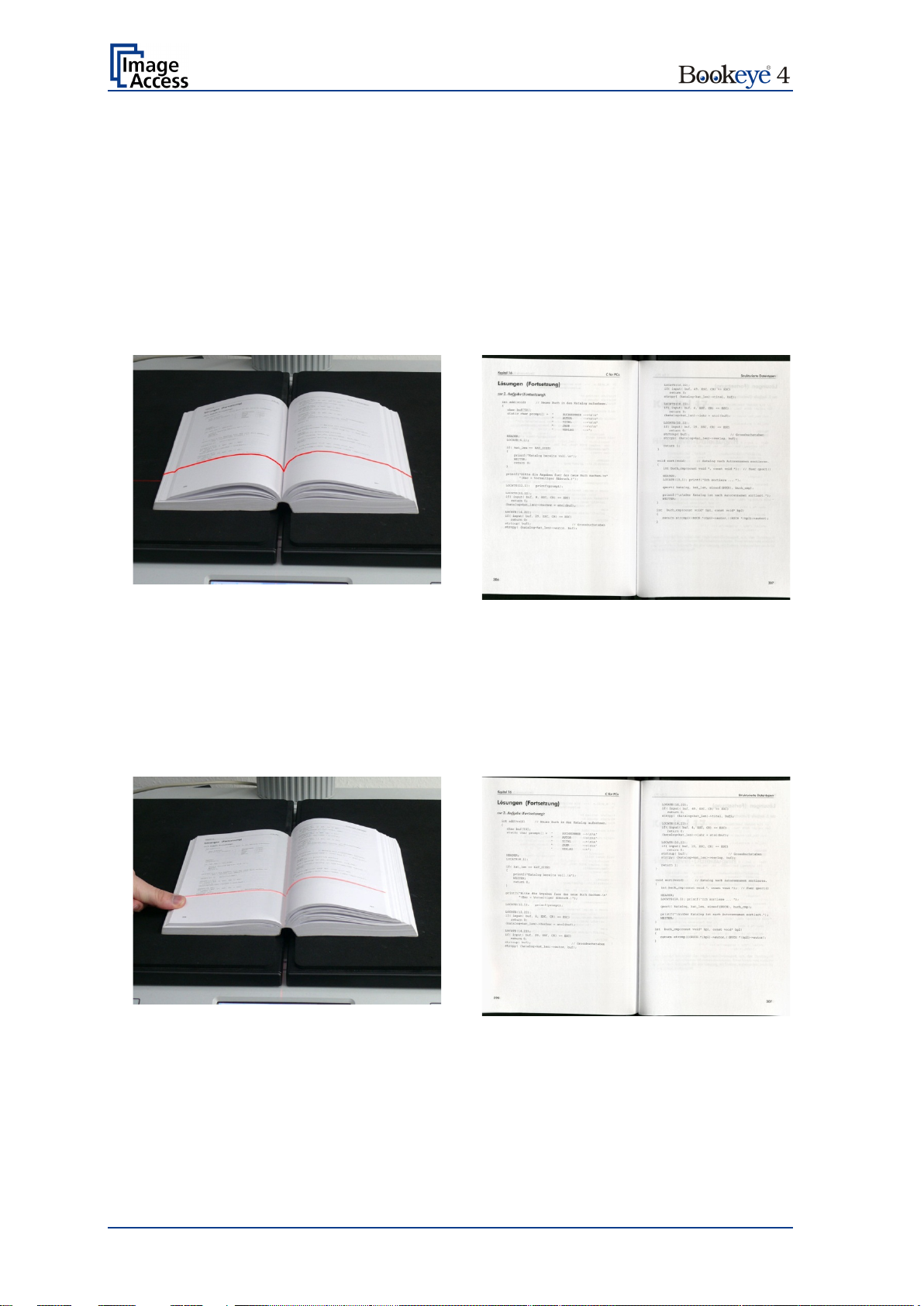
A.13.4 Working with the Book Cradle Plates
The book cradles can be moved up and down by using the Cradle Up and Cradle Down
buttons.
Place the document, e.g. a book, on the cradle plates and open t he cradle plates until the
book spine can freely move between the book cradle plates.
Picture 16: Book cradle plates opened
When setting the height of the book cradle plates, the target is to have both sides of the
book on nearly the same height before closing the glass plate. Picture 16 shows an
example.
If the height between the left and the right side differs (see Picture 17), the height of the
book cradle plates can be moved manually.
Picture 17: Book prepositioned at book cradle
The plates of the book cradle move simultaneously in opposite directions. That means, if
one plate is lowered, then the other plate lifts automatically.
Operation Manual Page 39
Page 40

Push the book cradle down manually until both sides of the document are at the same
height.
Picture 18: Lowering the book cradle
Activate the magnetic lock of the glass plate by pressing the Cradle Lock button. The
button is illuminated in blue
Move down the glass plate until the cradle lock engages.
When the cradle lock engages, you will hear a “click” sound and the Cradle Lock button
turns red.
Page 40 Operation Manual
Page 41

If necessary, move the cradle plates up or down in s mall steps with the cont rol buttons to
optimize the document’s position below the glass plate.
Picture 19: Glass plate closed
The cradle lock has a limited force for security reasons.
After successfully adjusting the book cradle height and the appropriate pressure, the
cradles support the weight of the book. The cradle plates can now be rocked up and down
without the motor being involved.
While scanning, the glass plate holds the same pressure on the book with respect to the
glass plate, keeps the book height at the same level, and keeps the same distance
between the book and the camera.
Touch the Scan Now button on the touchscreen to start the scan sequence.
After scanning, the glass plate lock releases and the glass plate opens. It can be stopped
by the operator in the 45 degree position.
The only interaction necessary while scanning through the book is applying light manual
pressure on one of the book sides to keep it in equal distance to the glass plate. This is
not always required because when the glass plate is closed for the next scan, t he cradle
plates move automatically to a proper position.
Operation Manual Page 41
Page 42

A.14 The “Finger Removal” Functi o n
A.14.1 Position of Document
The Bookeye® 4 scanner offers a helpful function which detects fing ers at the margin of
books and eliminates them from the image. This is the “Finger Removal” function.
The following easy-to-understand requirements must be fulfilled to operate the
Bookeye
®
4 using the “Finger Removal” function properly:
• The book cradle can be set to “V” position or in flat position.
• Place the book as shown in Picture 19 or Picture 20 on the book cradle. Let a
small distance between the book’s bottom side and the lower margin of the book
cradle.
Please note: The following pictures show an earlier version of the Bookeye 4-V2 scanner housing.
Picture 20: Book at book cradle in flat position
Picture 21: Book at book cradle opened in “V” position
• The distance depends on the thickness of the book. The distance should be at
least the half of the thickness of the book.
• The book must be aligned parallel to the horizontal red laser line.
• The book fold area must be placed below the vertical red laser line.
Page 42 Operation Manual
Page 43

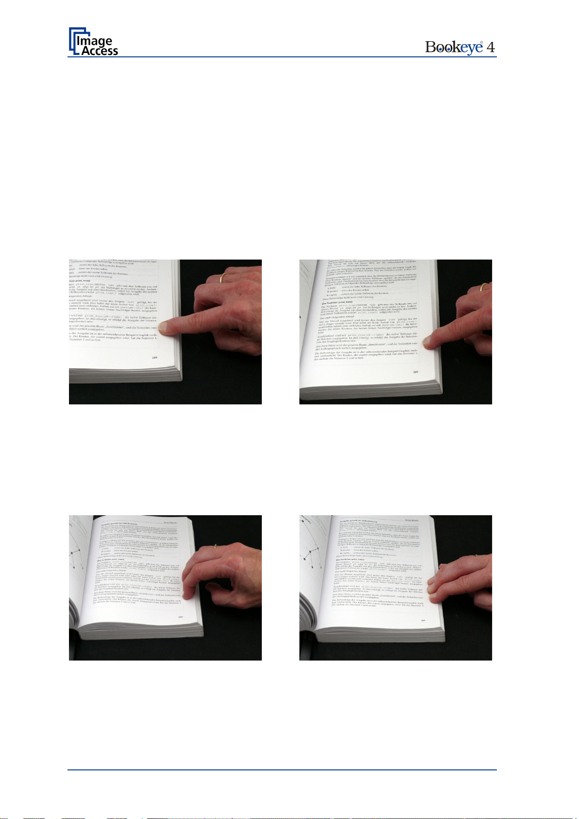
A.14.2 Finger Positions
Another important criterion for a proper function of t he “Finger Removal” function is the
position of the fingers which hold the book in a flat position.
• The fingers must be positioned in a vertical area of max 1 inch = 25 mm width
measured from the book fan at each side of the book.
Picture 22: Correct finger position
Picture 21 shows the vertical area marked with blue lines at the left side and the right side
of the book.
The book fan area on each side is also marked.
• The fingers must be positioned with a distance of at least a third of the book side
length from the upper left corner of the book.
Picture 23: Minimum vertical distance
Holding the book at both sides with one or more fingers is also possible if the above
described criteria are kept.
Operation Manual Page 43
Page 44
Wrong
Correct
Wrong
Correct
A.14.3 Wrong Finger Positions
Some finger positions can cause malfunction of the “Finger Removal” function.
The following chapters show a few examples of wrong and correct finger positions.
A.14.3.1 Distance too small
The fingers should be positioned with distance to the text or to graphical elements in t he
document.
If the distance is too small, the “Finger Removal” function may not remove the fingers from
the image or the element (e.g. part of the text) will be removed together with the fingers.
Increase the distance between finger and text or picture.
A.14.3.2 Finger position too steep
When the book cradle plates are set to “V” position, the lamps may generate shadows
around the fingers if they held too steep.
Always place the fingers flat on the edge of the document.
Page 44 Operation Manual
Page 45

Wrong
Correct
A.14.3.3 Fingers hold too close to the margin of the document
When the fingers are hold too close to the document’s margin, they will not be removed
by the “Finger Removal” function.
Move the fingers in small steps from the edge of the document to the inside and repeat
the scan sequence.
Operation Manual Page 45
Page 46
Book position
Scan result
Book and finger position
Scan result
A.14.4 Examples of Finger Removal
Some examples in the following chapter show the functionality of the “Finger Removal”
function. A requirement is that in the ScanWizard user interface or in the kiosk application
(see chapter B.3.1 and B.3.1.2) the scanner is set to Book Mode.
A.14.4.1 Book positioned at the book cradle
Book Mode, Finger Removal Mode: Book Fan
The setting „Finger Removal Mode: Book Fan“ cuts away the left and right book fan from
the resulting image and flattens the curvature of the book binding.
A.14.4.2 Single finger holds the book
Book Mode, Finger Removal Mode: On, Finger Removal Color: Auto
This setting corrects the resulting image as with the previous setting.
Additionally the finger contour will be detected. It is eliminated in the image and the finger
contour area is filled with a pattern and/or color.
The filling color is automatically taken from the area above and below the finger contour.
Page 46 Operation Manual
Page 47

Book and finger position
Scan result
Book and finger position
Scan result
Book Mode, Finger Removal Mode: On, Finger Removal Color: Black
Note: The Finger Removal Color is defined in the ScanWizard user interface.
The resulting image now shows the area where the finger contour was detected. The
detected area is filled with massive black color.
Small book kept flat by single finger
Book Mode, Finger Removal Mode: On, Finger Removal Color: Black
Note: The Finger Removal Color is defined in the ScanWizard user interface.
The “Finger Removal” mode works properly with books of different dimensions.
The scan result shows for demonstration purposes the detected finger contour filled with
massive black color.
Book position on the book cradle:
Operation Manual Page 47
Page 48

Book and finger position
Scan result
Large book (e.g. catalogue) kept flat by single finger
Book Mode, Finger Removal Mode: On, Finger Removal Color: Auto
Note: The Finger Removal Color is defined in the ScanWizard user interface.
The book fan has been removed and the surrounding black area is reduced to a minimum.
The scan result shows in the lower left corner a part of the finge r .
The reason is that the analyzing algorithm detected at the left border of the image an area
of mixed pat t erns and colors. In this case, it is the register of the catalogue.
The finger at the lower left edge was interpreted as part of the register. For this reason the
finger removal was not executed.
Page 48 Operation Manual
Page 49

Book and multiple fingers position
Scan result
Book and multiple fingers position
Scan result
A.14.4.3 Multiple fingers hold the book
Book Mode, Finger Removal Mode: Book Fan
Small book kept flat by multiple fingers
Book Mode, Finger Removal Mode: On, Finger Removal Color: Auto
Note: The Finger Removal Color is defined in the ScanWizard user interface.
If parts of the content of the book are covered by a finger or by multiple fingers, the
removal function detects the contour and fills the area with the selected fill option.
The white arrows in the scan result image mark the area where the finger contours have
been filled with automatically defined color.
Operation Manual Page 49
Page 50

Book and multiple fingers position
Scan result
Book Mode, Finger Removal Mode: On, Finger Removal Color: Auto
Note: The Finger Removal Color is defined in the ScanWizard user interface.
The position of the three fingers has been detected.
The fingers contour is eliminated in the resulting image and filled with a pattern and/or
color.
If Finger Removal Color is set to Auto the filling color and/or pattern is automatically
taken from the area above and below the finger contour.
When the detected finger contour is filled with massive black, the result looks like this:
Page 50 Operation Manual
Page 51

Book position
Scan result
A.14.4.4 Small books with pattern at margin
If a book has small dimensions, the finger removal mode Book Fan very often delivers
good results without flattening the book by fingers.
Book Mode, Finger Removal Mode: Book Fan
The scan result shows the content of both pages. The curvature of the book binding is
flattened and the pattern at the margins has been removed.
Position of the book on the book cradle:
Operation Manual Page 51
Page 52

A.15 The “Splitting” Function
Another useful function of the Bookeye® 4 scanner is the “Splitting” function.
This function splits the scanned document into two separate images. The left and the right
page of an opened book can be scanned in one sequence and subsequently be saved as
two images, or two sheets of paper can be scanned without interr uption and saved as two
separate images.
Another benefit is the combination of document mode Auto, format Crop and Deskew
and the “Splitting” function.
A.15.1 “Splitting” function wi t h two separate documents
Picture 23 shows as an example how single pages can be positioned at the book cradle
plates.
Please note: The following pictures show a former version of the Bookeye 4-V 2 scanner .
Picture 24: Single pages on book cradle plates
In general: T he sheets should have a distance of at least 25 mm (1 inch) to the gap
between the book cradle plates.
The black area around the sheets is necessary for the Auto Format
detection and for the Crop and Deskew function.
Define the settings in the touchscreen menu as follows:
Document Mode: Auto Mode (see B.3.1.1) or Flat Mode (see B.3.1.3)
Format: Crop and Deskew (see chapter B.3.3.3)
Splitting Image: Auto (see chapter B.3.4)
Define the settings in the ScanWizard interface (see Picture 90) as follows:
Size menu Flat Mode or no defined mode, which results in automatic selecting
the matching mode
Size menu Format Auto or Crop and Deskew
Orientation Splitting Image Auto
The second image is delivered after pressing the Scan Now button (touchscreen) or the
Scan Now icon (ScanWizard user interface).
Page 52 Operation Manual
Page 53

A.15.2 “Splitting” function with a single document
Select the settings as described in chapter A.15.1
Picture 25: Single document on book cradle plate
With a single document placed on a book cradle plate the scanner displays only the
scanned image on the external monitor or in the browser window (S2N user interface).
For the empty side of the book cradle the scanner shows the Bookeye screen saver
screen.
The ScanWizard interface shows an error message in a separate window.
Click on the OK button to confirm the error message.
If the document is placed at the right side of the book cradle, the error message is send at
first.
To get the imag e, press the Preview or Scan Now button in the S2N user interface again.
Operation Manual Page 53
Page 54

A.15.3 “Splitting” function with single document at middle of
the book cradle plates
Depending of the alignment of the document and of the selected Format mode, the
results of the “Splitting” function differ.
Format: Crop and Deskew
Parameters set as follows:
Document Mode: Auto Mode
Format: Crop and Deskew
Splitting Image: Auto
Starting at the vertical gap between the left book cradle plate and the right book cradle
plate the “Splitting” function measures to the left the distance to the edge of the document.
The measured distance gives the width for the left part of the split image.
Picture 26: Document position on book cradle plates
Picture 27: Splitting result with Format = Crop and Deskew
After splitting the images will be aligned (deskew) and the surrounding black border will be
deleted.
Page 54 Operation Manual
Page 55

Format: Auto
Parameters set as follows:
Document Mode: Auto Mode
Format: Auto
Splitting Image: Auto
If the document is placed in the middle of the scan area the image is split along the
detected middle of the document
Picture 28: Splitting result with Format = Auto
The resulting images show the parts of the document with a black border. These images
show the left and the right half of the scanned document.
Operation Manual Page 55
Page 56

A.15.4 “Splitting” function wi t h a book
It is recommended to s et the book cradle plates into “ V” position when scanning books or
other documents with a book spine.
Picture 29: Book cradle plates set to “V” position
The book cradle plates can be shifted horizontally from each other (see chapter 0). This is
recommended for books with a large book spine.
Picture 30: Large book at book cradle in “V” position
Define the settings in the touchscreen menu as follows:
Document Mode: Book Mode (see B.3.1.2) or Auto Mode (see B.3.1.1)
Format: Auto (see chapter B.3.3.2)
Splitting Image: Auto (see chapter B.3.4)
Define the settings in the ScanWizard interface as follows:
Size Book Mode or Size V- Mode
Size Format Auto or Size Format Crop and Deskew
Orientation Splitting Image Auto
The “Splitting” function detects the curvature of the binding and splits the document at this
position.
Page 56 Operation Manual
Page 57

A.15.5 Document positions which can result in malfunction
A.15.5.1 Single pages
Always place single pages on the book cradle which is in flat position.
Position the single pages with at least a minimum distance of 25 mm (1 inch) between the
pages.
Picture 31: Wrong position of book cradle and pages
Picture 30 shows two errors:
The book cradle plates are set to “V” position.
The pages are placed too close to each other.
A.15.5.2 Books
Books should always be aligned along the laser line and the book cradles plates should
be set into “V” position.
Picture 32: Book in bad position for splitting
In the above displayed situation, the “Splitting” function splits the image along the vertical
laser line.
If the rotation angle between book and laser lines is too large, the “Crop and Deskew”
function cannot turn the image for a proper result of the “Splitting” function.
Operation Manual Page 57
Page 58

touch a free section in the title line of the
Touching this button switches to the start screen of the integrated
B Touchscreen Operation
The Bookeye® 4 scanner can be controlled in two ways.
• Via the integrated touchscreen. The functions of the touchscreen are described
starting with chapter B.2.
• Via a standard browser and the ScanWizard user interface. A short description of
the functions of the integrated ScanWizard user interface starts in chapter C.1.
Please note: All screenshots are taken from a fully equipped device with all options and
functions activated. Depending on the selected mode, the menus displayed
on the screen can vary.
GENERAL NOTICE
®
This manual describes the functions of a complete equipped Bookeye
device is not equipped with all features, deviations are possible.
B.1 Select Application Screen
When the Bookeye® 4 scanner starts from standby mode and finishes the startup
procedure, the touchscreen displays for approximately ten seconds the screen
Select Application.
4 scanner. If your
Picture 33: Start screen af ter start -up
Touching this button will switch to a user programmable application.
As factory default the EasyScan application is integrated.
To leave the application,
application. Confirm the request by touching the STOP button.
kiosk application.
Chapter B.2 to chapter B.6 and the corresponding subchapters describe the available
functions of the kiosk a pplication.
Page 58 Operation Manual
Page 59

B.2 Start Screen of the Kiosk User Interface
After touching the S2N Scan2Net the kiosk application starts with the
Viewer&Job Control screen.
Picture 34: Viewer & Job Control screen
The touchscreen is structured in four sections, which allow operators to control and select
various functions of the scanner.
1: This section shows the main controls or parameters depending on the selected
control field in section 2.
2: Control fields to select the menu screens directly.
3: This section shows the status of the scanner, e.g. “Ready to scan, allows starting
the scan sequence by touching Scan Now, allows returning to the start screen, and
displays date and time.
4: The content of this section changes dependent on the selected control field in
section 2. More specific information can be found in the respective chapters.
Operation Manual Page 59
Page 60

B.2.1 Control Fields of the Touchscreen
By touching the buttons in section 2 each menu screen can be reached directly.
The chapters B.3 to B.6 describe the functions of the menus in detail.
Touch this button to start the scan sequence.
Touch this button to return to the start screen from every other menu.
……
If available, this two arrow buttons switch to the next or to the previous menu screen.
Touch this button to return to the main menu.
Touch this button to set all parameters to default values.
Touching this button opens an additional window. The additional window contains short
information about the available functions.
Page 60 Operation Manual
Page 61

B.3 Touchscreen – Document Source
The Document Source screen allows selecting from a wide range of scan parameters.
Picture 35: Document Source screen
The content of the menus which are selectable with the buttons can vary.
This depends on the selected document mode.
The variation affects specially the content of the Format menu. A deta iled description can
be found in chapter B.3.3 and the following subchapters.
Operation Manual Page 61
Page 62

B.3.1 Document Mode
The Document Mode setting defines the focusing method when scanning documents.
Picture 36: List of Document Modes
B.3.1.1 Auto Mode
This mode automatically detects the position of the book cradle and the type of docu ment
to be scanned. The focus is set depending on the detected document mode that matches
the best.
The Auto Mode selects automatically between Flat Mode, Folder Mode or V-Mode.
Please note: The document should always be placed in the horizontal middle of the book
cradles. The laser lines cross must be visible at the document.
Document minimum width must be ten centimeter.
A minimum of four centimeters of the documents width must be placed left
from the laser lines cross.
The Auto Mode function cuts the image to a rectangle which covers the
four document corners. If the document is not aligned properly to the laser
lines, a small black border is displayed around the document.
If the document is too small, the image shows the complete scan area.
Page 62 Operation Manual
Page 63

Example for correct document position …
…and image result
Example for false document position …
…and image result
B.3.1.1.1 Document Position / Minimum Document Size
Please note: The following pictures show a former version of the Bookeye 4 scanner.
Picture 37: Document placed correctly
Image shows only the document
Picture 38: Document placed incorrectly
Operation Manual Page 63
Image shows both book cradles
Page 64

The focus value will be set dependent on the
focus value will be used for the
To be used when the book cradle is positioned in the
Sets separate focus values for the left and right book
is recommended when scanning
icant height differences on
B.3.1.2 Book Mode
B.3.1.3 Flat Mode
Recommended method for scanning books.
The book binding curvature will be compensated and
flattened out. The focus will be set depending on the
form of the book and its curvature.
The focus will be set depending on the position of
the book cradle plates.
If the book cradle plates are set in “V” position the
focus will be set dynamically according to the
detected book curvature.
document height.
B.3.1.4 V-Mode
B.3.1.5 Folder Mode
The measured
complete scan area.
“V” position.
The focus will be dynamically set dependent on the
“V” position of the book cradle.
cradle plates.
This mode
documents with signif
each side.
Page 64 Operation Manual
Page 65

B.3.2 Resolution
The Resolution setting allows selecting a resolution from a list of resolution values
supported by the Bookeye
®
4 scanner.
Picture 39: List of Resolutions
Touch the blue arrow beside the currently selected value to open the list of available
resolutions.
Select the desired value by touching the value in the list.
The list closes and the selected value is displayed.
Operation Manual Page 65
Page 66

Document Mode
Format
B.3.3 Format
The Format button allows defining the scan area size.
The bottom line of the button Format shows the current format setting.
Picture 40: Selector for Format settings
Depending on the Document Mode selected, the available formats will vary.
The table below shows the dependencies between Document Mode and Format.
Auto Mode Maximum Landscape / Portrait left / Portrait right
Auto Finger Removal Mode (Off / Book fan / On)
Crop and Deskew
Book Mode Auto Finger Removal Mode (Off / Book fan / On)
Flat Mode Maximum Landscape / Portrait left / Portrait right
Auto Finger Removal Mode (Off / Book fan / On)
Crop and Deskew
DIN
ANSI
V-Mode Maximum Landscape / Portrait left / Portrait right
Auto Finger Removal Mode (Off / Book fan / On)
Folder Mode Maximum Landscape / Portrait left / Portrait right
Page 66 Operation Manual
Auto Finger Removal Mode (Off / Book fan / On)
Crop and Deskew
DIN
ANSI
Page 67

B.3.3.1 Maximum
With Maximum three buttons will be displayed.
Picture 41: Parameters for Maximum format
Landscape Scans the maximum scan area in landscape orientation.
Portrait left Scans the area left from the gap between the book cradle plates in portrait
orientation.
Portrait right Scans the area right from the gap between the book cradle plates in
portrait orientation.
Press this button to return from a submenu to the main menu.
Operation Manual Page 67
Page 68

Document at book cradles
Resulting image
B.3.3.2 Auto
The complete scan area will be scanned.
Picture 42: Book Mode Formats
Auto
The resulting image will be reduced to the document size. If the document is not aligned
to the horizontal and vertical red laser lines the resulting images will have the smallest
possible black margin.
The black margin depends on the size of rectangle which covers the complete document.
Example: Scanning with Format Auto:
Press this button to return from a submenu to the main menu.
Page 68 Operation Manual
Page 69

B.3.3.2.1 Finger Removal Mode
The Finger Removal Mode allows selecting from three settings.
Off Disables the Finger Removal Mode.
Book Fan The book fan at the left and right side will be detected and eliminate from the
image.
On The book fan at the left and right s ide will be detected and eliminate from the
image. If the book is kept flat by one or multiple finger s, the contour of the
fingers will be detected and removed.
The detected contour then will be filled with black or white color or with an
automatically detected pattern. The pattern depends on the color which is
found in the image below and above the finger contour.
Read chapter A.14 and its subchapters for detailed information about the criteria and the
requir ements of the Finger Removal Mode.
Please note: If the document is hold at bot h sides in its position, it is recommended to
use a foot pedal for starting the scan sequence.
Operation Manual Page 69
Page 70

Document at book cradles
Resulting image
B.3.3.3 Crop and Deskew
The complete scan area will be scanned.
Picture 43: Crop and Deskew screen
If a document is not placed perfectly aligned horizontally and vertically, this function will
correct the alignment.
The resulting image shows the aligned document without any border.
Example: Scanning with Format Crop and Deskew
Please note: I n document mode Book Mode this function is not available. The image of
two single pages pos itioned at the left and the right book cradle plates will
only be cropped to the size of a rectangle which covers both pages.
The images will not be aligned as shown in the above example for the
resulting image.
If Splitting Image (see chapter B.3.4) is active, two images will be
displayed. Each image shows the respective document, surrounded by a
black rectangle. The black rectangle encloses the complete document. The
resulting image will not be aligned (= deskewed).
Press this button to return from a submenu to the main menu.
Page 70 Operation Manual
Page 71

B.3.3.4 DIN
When selecting DIN, an additional small window is displayed in the touchscreen.
It contains the available DIN (=ISO) paper sizes.
Picture 44: Format DIN (=ISO) selected
Depending on the selected paper size the buttons for Landscape, Portrait left and
Portrait right are inactive (= gray) or active.
Landscape:
Press the button to scan the selected size in landscape orientation. The scan area is
symmetrically to the horizontal middle at the lower margin of the book cradles.
Portrait left / Portrait right:
Press the button to scan the selected size in portrait orientation. The scan area starts left
respectively right from the horizontal middle at the lower margin of the book cradles.
Press this button to return from a submenu to the main menu.
Operation Manual Page 71
Page 72

B.3.3.5 ANSI
When selecting ANSI, an additional small window is displayed in the touchscreen.
It contains the available ANSI paper sizes.
Picture 45: List of ANSI formats
Depending on the selected paper size the buttons for Landscape, Portrait left and
Portrait right are inactive (= gray) or active.
Landscape:
Press the button to scan the selected size in landscape orientation. The scan area is
symmetrically to the horizontal middle at the lower margin of the book cradles.
Portrait left / Portrait right:
Press the button to scan the selected size in portrait orientation. The scan area is left
resp. right from the horizontal middle at the lower margin of the book cradles.
Press this button to return from a submenu to the main menu.
Page 72 Operation Manual
Page 73

Auto
The complete scan area will be
scanned. The resulting image size will
be detected and it will be divided into
displayed successively as separate
again to show the
B.3.4 Splitting Image
The button Splitting Image is used to select splitting the document scanned for the output
images.
Picture 46: Splitting Image
Left: The selected format will be scanned completely. Only the left half of the selected
format will be displayed.
Right: The selected format will be scanned completely. Only the right half of the
selected format will be displayed.
two symmetrical parts. Both parts will be
images.
Press Scan now
second part of the document.
If selecting Auto, an additional selector
opens. Here the page that will be
Picture 47: Selecting the „Splitting Start Page“
displayed first can be selected as a start
page.
Press this button to return from a submenu to the main menu.
Operation Manual Page 73
Page 74

B.3.5 Scan Mode
The Scan Mode screen allows the user to select from two possible scan modes.
Picture 48: Available Scan Modes
High Quality Scans with reduced scanning speed but improved scanning quality.
Fast Scans with normal speed, depending on the selected scan resolution.
In general, the scan speed depends at the selected resolution.
That means, the higher the resolution, the lower the scan speed.
Page 74 Operation Manual
Page 75

Black Cut
Sets the threshold for black. All pixel values found in the image below
Auto
Sets the threshold for black and activates the automatic exposure
est and the
The detected brightness range is expanded to the
Otherwise all values below the
B.3.6 Exposure
The Exposure screen allows selecting the functions Black Cut and Auto.
Fixed switches the function off.
Picture 49: Exposure Modes
When Black Cut or Auto is selected a numeric key pad opens.
Picture 50: Numeric key pad to set threshold value
0 (zero) to 100
0 (zero) to 100
the selected value are set to solid black.
Result: The image contrast is improved.
control.
This function analyzes the image and detects the bright
darkest area.
maximum range of the scanner.
threshold are defined as “black”.
Result: Automatic contrast control and the image contrast is improved.
To set a new value, touch in the line of the displayed value and erase the value with the
DEL button.
Enter the new value with the key pad and touch Send to send the new value.
Operation Manual Page 75
Page 76

B.3.7 Auto Density [Binary]
This parameter defines the scanner’s sensitivity for the automatic format detection.
Default value: 40
Picture 51: Auto Density slider
When scanning dark documents, the value should be reduced in small steps until the
desired result is achieved.
Please note: The higher the numeric value, the more contrast there must be between
background and scanned document.
The default value is marked below the scale by the green “40”.
Page 76 Operation Manual
Page 77

B.4 Touchscreen – Image Quality
The Image Quality screen allows setting a wide range of image quality parameters.
Picture 52: Image Quality 1
In color mode Binary two additional menu items will be displayed.
These are the menu items Invert and Despeckle.
Picture 53: Image Quality 2
Operation Manual Page 77
Page 78

B.4.1 Color Mode
By touching the selection arrow of the Color Mode section the list of available color
modes opens.
Picture 54: List of Color Modes
Touch the title of the desired color mode to select the mode. The list closes subsequently.
Picture 53 shows the available color modes.
B.4.2 File Format
Press the File Format button to select a file format for the images.
B.4.2.1 JPEG
Picture 55: Submenu File Format “jpeg”
Depending on the file format selected, some additional parameters will be displayed.
With the JPEG file format, a value for the image quality can be entered by the numeric
key pad.
This value determines the compromise between quality and compression rate. A higher
quality factor produces larger files. The default setting of 75 is a good compromise for
most documents.
Page 78 Operation Manual
Page 79

B.4.2.2 TIFF
Picture 56: Submenu File Format TIFF
With the TIFF file format, the compression method of the file can be selected with the
TIFF Compression buttons.
CCITT G4 Recommended with color mode “Binary”.
JPEG Recommended for all other color modes.
None Disables the data compression.
B.4.2.3 PNM
With the PNM file format, no additional parameters are available.
B.4.2.4 PDF
With the PDF file f ormat, the same compression methods are available as with t he TIFF
format (see picture above).
Press this button to return from a submenu to the main menu.
Operation Manual Page 79
Page 80

B.4.3 Brightness
Picture 57: Brightness slider
The Brightness slider defines the resulting brightness in the image. Lower brightness
values result in darker images, higher values result in brighter images.
Values close to 0% or to 100% may result in unwanted artifacts.
Move t he slider indicat or to the desired position to set the value.
B.4.4 Contrast
Picture 58: Contrast slider
The Contrast slider defines the contrast in the image. Lower contrast values result in
“smoother” images; higher values show more details and the images become “crisper”.
Values close to 0% or to 100% may result in unwanted artifacts.
Move the slider indicator to the desired position to set the value.
B.4.5 Gamma
Picture 59: Gamma slider
The Gamma slider defines the gamma correction directly inside the camera electronics. A
value of 1.7 is a good approximation for most documents.
Higher gamma values show more details in dark areas and compress bright areas of the
image.
Move the slider indicator to the desired position to set the value.
B.4.6 Image Sharpness
Picture 60: Image Sharpness
The Image Sharpness slider invokes an advanced automatic sharpening algorithm which
sharpens the image before any other operation is performed.
The value “zero” disables the function. Very high values may produce artifacts depending
on the type of document.
Move the slider indicator to the desired position to set the value.
Page 80 Operation Manual
Page 81

B.4.7 Image Rotation
Picture 61: Image Rotation
The value selected from the list defines the rotation of the image in a clockwise direction.
The image will be rotated directly after scanning and before display
B.4.8 Mirror
Picture 62: Mirror
This control mirrors the image along the selected mirror axis.
Using this setting can be helpful if scanning transparencies from the back.
B.4.9 Invert
Picture 63: Invert
This control is only available with the color modes Binary and Photo.
B.4.10 Despeckle
Picture 64: Despeckle
(Only available in Binary color mode)
Available modes are 4x4p and Off.
Operation Manual Page 81
Page 82

The ICC profile for the external monitor is integrated into the image
(1)
B.5 Touchscreen – Viewer & Job Control
The Viewer Control screen allows the operator to control and modify the image on the
TFT flat screen.
Picture 65: Viewer & Job Control screen
The preview section (1) represents the TFT flat screen.
The scanned image is displayed on the TFT flat screen and with reduced quality in the
preview section right beside the controller elements.
Picture 66: Scanned image in preview area
if the checkbox is selected.
Page 82 Operation Manual
Page 83

The middle circle contains the keys to
The controller is structured in three round elements (circles).
The outer circle contains the keys to move the zoomed area
across the image.
zoom in
zoom out
rotate the image in clockwise direction in steps
of 90 degrees
scale the image to the real size of the source
document. A centered cutout of the image is
displayed on the TFT flat screen.
The inner circle symbol allows selecting between two
settings. It shows the selectable setting, not the selected
setting.
Touching this symbol displays the image with its genuine
dimensions (100%), depending on the resolution selected
for scanning.
Touching this symbol displays the complete image on the
TFT flat screen. The image will be scaled to a size that
matches the screen size.
Table 1: Controller circles and their functions
Operation Manual Page 83
Page 84

OCR button
B.5.1 Zonal OCR
The Bookeye® 4 offers a zonal OCR function. This function can be activated by the button
positioned right below the preview section.
Zonal OCR means, that only the marked area will be processed by the OCR function. Text
and line feed will be found only. A layout analysis will not be executed.
Prior using the zonal OCR it is required to set the scan parameters as follows:
Format: Crop and deskew
Resolution: Between 300 dpi and 400 dpi.
File format: PDF
Scan the document. The preview section of the touchscreen shows the image with
reduced resolution. After scanning, the OCR button below the preview section is active.
Picture 67: OCR button activated
Press the OCR button. The touchscreen change and shows the image and the control
buttons for the OCR function.
Picture 68: OCR touchscreen
Page 84 Operation Manual
Page 85

Touch the image at an arbitrary position. A red rectangle will be displayed.
Picture 69: Rectangle defines the area for OCR function
Exit: Press Exit to return to the former screen.
CUT: Press the CUT butt on. The next screen will display the defined area
more detailed.
CLR: Press CLR to delete the defined area.
OCR: Press OCR to start the OCR process.
OCR Language: Press the Up/Down arrows to select a language which is used for the
OCR process.
At first, only CUT is active.
Touch the arrows at the sides of the rectangle to define the dimension and the position of
the area where the OCR function should be executed.
This is the first step and can be understand as a “pre”-selection.
Whenever the dimensions of the rectangle have been modified, it c hanges the color from
“Red” to “Gray”.
Picture 70: Pre-selection area selected
Operation Manual Page 85
Page 86

Press CUT to separate the previously defined area from the complete image and to
display it in detail.
Picture 71: Selected area mag nif ied
The next screen shows the selected area magnified and allows again defining an area for
the OCR process.
Press OCR to start the OCR process.
Press CLR to return to the former screen and to repeat the definition of the OCR area.
The result of the OCR process will be displayed in the touchscreen.
Picture 72: OCR result
The OCR result shows only the plain text with line feeds, a layout analysis will not be
offered.
The text can be edited by the user with the keyboard displayed at the touchscreen.
Generate PDF: Generates the PDF file of the text, detected by the OCR analysis.
The touchscreen will return to the Viewer&Job control screen (Picture 64).
Press the Send to button to save the image together with the text as PDF file.
Page 86 Operation Manual
Page 87

B.5.2 Job Mode
The bottom line of the Viewer & Job Control screen is different to the bo ttom line of the
other screens.
Picture 73: Bottom line with status
The bottom line shows
• the current scan mode status,
• the button to switch the job mode between Single and Job mode
• a scan counter between the question mark symbol and the “arrow right” symbol.
The default scan mode is Single. The button shows the selectable scan mode.
After selecting Job mode the T FT flat screen displays an “Information Panel” at the left
margin.
Picture 74: TFT flat screen after selecting “Job mode”
The Information panel contains:
Scan counter: Number of images since starting Job mode.
File size: Size of all scanned images since starting Job mode.
Free Space: Remaining storage volume in percent.
<Date Time>: Current date and time
Operation Manual Page 87
Page 88

Before scanning the touchscreen displays a disclaimer, which has to be accepted.
Picture 75: Disclaimer when staring the Job mode
After accepting the disclaimer, the Viewer&Job Control screen opens.
It contains some additional control buttons above and below the preview section.
Picture 76: Job mode start screen
Page 88 Operation Manual
Page 89

Moves up- and/or downwards through the list of images to mark
B.5.2.1 Navigating through the list of images
The control buttons allow navigation through the list of scanned images and image
handling while working in Job mode.
The currently scanned image is always displayed in the preview section of the
touchscreen and will be added as last image to the list displayed at the TFT flat screen.
Function of the control buttons:
an image.
After an image has been selected from the list, it is marked in the list with a dark frame.
Moves a selected image up- and/or downwards.
Selects an image from the list. A red frame marks the image.
Selects the position where an image should be inserted.
Deletes the selected image.
The control buttons for available actions will be activated, i.e. they will be displayed in full
color.
The image which was scanned last is marked with a “pencil” symbol in the list. This
symbol signalizes that the image can be modified with the functions in section
Image Quality.
The controller circles will be blanked out if another image than the last one scanned is
selected.
Picture 77: Controller circles blanked out
After selecting an image for rescanning, the button
changes to
Operation Manual Page 89
.
Page 90

Press this button to select the image. The image now can be moved with
This control button darkens the background of the selected frame. The
B.5.2.2 Moving an image to another position
Use the upwards / downwards buttons to mark the image to be moved.
the upwards / downwards buttons to the new position.
Press this button again to place the image at the new position.
B.5.2.3 Adding an image at an any position to the list
Use the upwards / downwards buttons to move to the position where the new image
should be added.
image to be added will be inserted before the selected image. The image
list will be renumbered.
Press the Scan Now button to start the scan sequence and to add a
new image to the list at the selected position.
B.5.2.4 Deleting an image from the list
Use the upwards / downwards buttons to move to the image which should be deleted.
Use this button to select the image to be deleted.
Press this button to delete the selected image.
B.5.2.5 Rescan an imag e
Use the upwards / downwards buttons to move to the image which should be rescanned.
Use this button to select the image.
Press this button to rescan the image. The image will be inserted at the
selected position.
Page 90 Operation Manual
Page 91

B.5.2.6 Finalizing the Job mode
Before finalizing the Job mode the scanned images can be transferred to different
destinations.
Picture 78: Destination to finalize Job mode
The destinations are identical to the destinations described in chapter B.6 and its
subchapters.
Before the Job mode will be finalized, a message is displayed at the touchscreen.
Confirm the message to finalize the Job mode or select No to return to the menu.
B.5.2.6.1 Job mode time out
After two minutes of inactivity the Job mode is finalized automatically.
A message box pops up and a warning sound is audible.
Picture 79: Information when time out ends
Operation Manual Page 91
Page 92

B.6 Touchscreen – Send To
This menu provides the output options in order to transfer the scanned images to the
desired destination.
Picture 80: "Send To" screen #1
Due to the dimension of the touchscreen, not all output options can be displayed at the
same time. By using the scrollbar at the right side, the content of this menu can be moved.
Move the scrollbar to display all output option on the touchscreen.
Picture 81: "Send To" screen #2
When pressing the link below the respective button, the touchscreen content changes and
displays the option screen.
The chapters B.6.2 to B.6.6 describe the options to be changed or set from the
touchscreen.
Page 92 Operation Manual
Page 93

1
3
2
B.6.1 Changing a file name or other entries
In some of the option menus the file name can be changed.
To change the file name, touch the respective line.
The screen changes to an alphanumeric keyboard.
Picture 82: Alphanumeric keyboard
1: Use the arrow keys to position the cursor in the line.
2: Use this key to delete characters.
3: Use this button to switch between the keyboard layouts.
Ok: Touch this button to confirm the new entries and to return to the former screen.
Cancel: Touch this button to discard the new entries and to return to the former screen.
Operation Manual Page 93
Page 94

B.6.2 USB Options
Two USB connectors are available at the front of the scanner to connect suitable USB
data carriers, for example USB sticks.
Touching USB Options displays the directory of a connect ed USB data carrier.
Picture 83: Directory of connected USB data carrier
While the directory of the USB data carrier is displayed, the LED indicator of the
respective connector is continuously illuminated.
Touch Ok or Cancel to stop displaying the directory of the USB stick.
When data is transferred between the USB data carrier and the scanner the LED indicator
blinks.
Please note: When the blue indicator LED stops blinking, data transfer may still be in
progress. Before unplugging the USB media, wait a few seconds to avoid
loss of data.
B.6.2.1 List of suitable USB storage media
The criteria in the following list have been defined as a guide line for the storage media
that can be connected to the USB connectors.
• USB memory sticks,
• USB hard disks,
• USB hard disks without partition, with one or with multiple partitions, formatted with t he
file systems UDF, FAT, FAT16, VFAT, FAT32, NTFS, EXT2, EXT3 or ReiserFS
The file system EXT4, BTRFS, UFS, ZFS or exFAT currently will not be supported.
Page 94 Operation Manual
Page 95

B.6.3 Copy Options
Touch Copy Options to switch to the screen with the preset copy option configurations.
Three preset options can be stored and activated with the buttons Copy1 to Copy3.
Picture 84: Parameters of Copy Options
The parameters displayed in the above picture can only be changed from the Scan2Net®
setup interface, user level Poweruser.
B.6.3.1 Printer Settings
After pressing the button Copy image to remote printer an additional window opens.
Picture 85: Printer settings window
Here the user can select scaling of the image, the paper source and the number of copies.
The content of each line depends on the features of the connected printer.
Operation Manual Page 95
Page 96

B.6.4 FTP Options
Touch FTP Options to switch to the screen with the preset FTP server configurations.
Three preset FTP servers can be stored and activated with the buttons FTP 1 to FTP 3.
Picture 86: Parameters of FTP Options
From the touchscreen, only the entry for File Name can be changed.
To change the entry, touch the respective line.
Chapter B.6.1 describes how the entry can be changed.
All other parameters must be changed from the Scan2Net® setup interface, user level
Poweruser.
Page 96 Operation Manual
Page 97

B.6.5 Network Options
Touch Network Options to switch to the screen showing the preset network
configurations.
Three preset configurations can be stored and activated with the buttons Network 1 to
Network 3.
Picture 87: Parameters of Network Options
From the touchscreen, only the entry for File Name can be changed.
To change the entry, touch the respective line.
Chapter B.6.1 describes how the entry can be changed.
All other parameters must be changed from the Scan2Net® setup interface, user level
Poweruser.
Operation Manual Page 97
Page 98

B.6.6 Mail Options
Touch Mail Options to switch to the screen showing the preset email configurations.
Three preset configurations can be stored and activated with the buttons Mail 1 to Mail 3.
Picture 88: Parameters of Mail Options
To change an entry, touch the respective line. From the touchscreen the values for
• Recipient
• Mail Subject
• File Name
can be changed.
Chapter B.6.1 describes how the entries can be changed.
More parameters can be changed from the Scan2Net® setup interface, user level
Poweruser.
Page 98 Operation Manual
Page 99

B.6.6.1 Transaction modes
Two transaction modes are available for the mail transfer. The parameters for the
transaction modes can be set from the Scan2Net® setup interface.
The mode, selected in the Scan2Net® setup interface, influences the process when a
scanned image should be mailed.
Automatic When pressing the button Mail image via SMTP at the touchscreen, the
image will be sent to the address defined in the screen Mail Options
(Picture 87). The status area of the touchscreen above the Scan Now
button shows the message: Mail image via SMTP.
Interactive When pressing the button Mail image via SMTP at the touchscreen,
another window opens in the touchscreen. It is titled Mail Options and
allows entering another address for the recipient than the prescribed
address. All other settings remain the same.
To enter another address, click in the topmost line.
Picture 89: Interactive mode, mail options
All entered addresses will be saved in a list when Save is select ed with
the checkbox. Click at the selection arrow to see the list.
Using Interactive is recommended when transferring image to often
changing addresses.
Operation Manual Page 99
Page 100

C The ScanWizard User Interface
Essentially, the scanner is a web server and comes with its own HTML based user
interface, named ScanWizard.
A basic requirement before working wit h the integrated ScanWizard user interface is to
configure the browser as follows:
• Force the browser to reload the page content every time directly from the scanner
and not to load from the cache memory.
• Enter the scanner’s IP address in the exception list.
ScanWizard is a simple and intuitive user interface for your Scan2Net® scanner, which
can be accessed using any standard web browser. ScanWizard is operating system
independent and requires no installation of any kind on the user's client PC.
Once your network administrator has assigned the scanner an IP address and installed it
in your network, any user can access the scanner and operate it using ScanWizard.
Start your browser.
Enter the IP address which has been assigned to the scanner.
The default IP address of the scanner: 192.168.1.50
The Scan2Net® main menu will be displayed in the browser.
Picture 90: Scan2Net® main menu
Launch Scan Application switches to the ScanWizard interface. Information about the
ScanWizard interface will be found starting in chapter C.1.
Setup Device switches to the setup menu. If you have access rights to the
administrative parts of the Scan2Net® system, press this button to set up the device and
access information about the scanner. Information about the setup level User can be
found in chapter D.
Information gives a short summary of the device parameters. Information will be found
in chapter C.2.
Page 100 Operation Manual
 Loading...