

Page 1
Booookkeeyyee 44
B
Operation Manual
Preliminary Version
Page 2

File: BE4_OperationManual_PreLim_V2.doc
Page 3

2010 by Image Access GmbH, Wuppertal, Germany.
Printed in Germany. All rights reserved.
Reproduction in whole or in part in any form or medium without express written permission of
Image Access is prohibited. Scan2Net® is a registered trademark of Image Access. Other
designated brands herein are trademarks of Image Access.
All other trademarks are the property of their respective owners.
Image Access reserves the right to change the described products, the specifications or
documents at any time without prior notice. For the most recent version, always check our web
site www.imageaccess.de or the customer service portal at http://service.imageaccess.de
Operation Manual Page 3
Page 4

Introduction
Dear Customer,
We congratulate you on the acquisition of this innovative product from Image Access.
At Image Access, we are proud of the work we do; our products are the result of our
extremely high production standards and stringent quality control.
With the Bookeye 4, Image Access offers an efficient V-cradle book scanner which
covers a wide range of applications due to its versatility. The integrated web based
user interface enables access to all functions via a structured set of menus.
This operation manual is designed to lead you through the most typical situations
experienced when operating the Bookeye 4 scanner.
For this reason, we ask you to read the operation manual attentively before starting to
work with the device. By doing so, you will avoid operation errors and you can control
all functions effectively from the beginning.
In addition, please consider the following points:
Damages to your unit may have occurred during shipping. Please check for
damages immediately after delivery of the unit. Inform your supplier if damage
has occurred.
Read and ensure that you understand the safety notes. They were developed
for your protection and safety as well as to protect the unit.
Regular maintenance conserves the high quality and safety of the Bookeye 4
scanner during the entire service life.
If you have any further questions, please feel free to contact your local dealer or
Image Access, Inc. directly. Our staff will be happy to help you.
For your daily work with the Bookeye 4, we wish you success and complete
satisfaction.
Regards
Your Image Access Team
Page 4 Operation Manual
Page 5

About this Manual
Operation Manual
The Operation Manual provides all necessary information pertaining to the normal
operation and behavior of the device. It is written for people who only operate the
device and do not perform setup and adjustment procedures. All device elements and
software functions are described in detail, although some of them might never be used.
This manual does not cover any application software. Refer to the appropriate manual
to learn about the application software.
Setup and Assembly Manual
The Setup and Assembly Manual is written for technical staff with some basic
mechanical skills and software knowledge. Many resellers will offer on-site installation;
therefore, large parts or all of the setup and assembly manual may not be of interest to
the reader. The access level at which the setup and adjustment procedures are
performed is called “Power user”. This “Power user” level is password protected from
access by the normal operator.
All manuals can be downloaded from our customer service portal at
http://service.imageaccess.de
manuals.
This manual is divided into four sections, A to D.
Section A describes the hardware of the device and gives an overview of all
components and connectors of the scanner. Remember that this device
is a precise optical instrument and should be handled accordingly.
Section B describes the functions of the touch panel and how to setup specific
parameters.
Section C describes the functions of the integrated Scan2Net user interface.
Section D shows all technical information of the scanner .
. Be sure to always check for the latest versions of these
Operation Manual Page 5
Page 6

Version History
Version Published in Content/Changes/Supplements
August 2010 Preliminary version.
Page 6 Operation Manual
Page 7

Table of Content
Introduction--------------------------------------------------------------------------4
About this Manual -----------------------------------------------------------------5
Version History ---------------------------------------------------------------------6
A Hardware ----------------------------------------------------------------------- 13
A.1 Safety Notes .............................................................................................13
A.1.1 Marking of Safety Notes 13
A.1.2 Laser Safety Note 13
A.2 Device Overview.......................................................................................14
A.2.1 Connectors on the Rear Side 15
A.2.2 Content on Delivery 15
A.2.3 Connecting the Power Source 16
A.2.4 Starting the Bookeye 4 16
A.2.5 Switching the Bookeye 4 to stand-by mode 16
A.3 Device Location ........................................................................................17
A.3.1 Environment 17
A.3.2 Ambient Light 17
A.4 Book Cradles ............................................................................................18
B Software ------------------------------------------------------------------------ 20
B.1 Touch Panel – Start Screen (Send to) ......................................................20
B.2 Touch Panel – Document Source.............................................................21
B.2.1 Document Mode 21
B.2.2 Resolution 22
B.2.3 Format 22
B.2.3.1 Flat Mode Formats 23
B.2.3.2 Book Fold Correction Formats 24
B.2.3.3 V-Mode Formats 24
B.2.4 Splitting Image 25
B.2.5 Scan Mode 26
B.2.6 Exposure 27
Operation Manual Page 7
Page 8

Table of Content, part 2
B.3 Touch Panel – Image Quality................................................................... 28
B.3.1 Color Mode 29
B.3.2 File Format 29
B.3.2.1 JPEG 29
B.3.2.2 TIFF 30
B.3.2.3 PNM 30
B.3.2.4 PDF 30
B.3.3 Brightness 31
B.3.4 Contrast 31
B.3.5 Gamma 31
B.3.6 Image Sharpness 31
B.3.7 Image Rotation 32
B.3.8 Mirror 32
B.3.9 Invert 32
B.3.10 Despeckle 32
B.4 Touch Panel – Viewer Control ................................................................. 33
B.5 Touch Panel – Send to ............................................................................ 34
B.5.1 USB Options 34
B.5.2 Mail Options 35
B.5.3 FTP Options 36
B.5.4 Copy Options 37
B.6 Setup and Adjustments............................................................................ 38
B.6.1 White Balance 38
B.6.2 IP Address 39
B.6.3 Time and Date 40
B.6.4 User Settings 41
B.6.5 Focus and Scan Area 42
B.6.6 Scan CSTT 43
Page 8 Operation Manual
Page 9

Table of Content, part 3
Software Operation --------------------------------------------------------- 44
C
C.1 The Integrated User Interface...................................................................44
C.2 The Main Screen ......................................................................................45
C.2.1 The Options Screen 47
C.2.1.1 Book Fold Options 49
C.2.1.2 Embedded Meta Data 50
C.2.2 The Properties Screen 51
C.2.3 The Camera Screen 55
C.2.3.1 Threshold Dynamic / Threshold Fixed 58
C.2.3.2 Despeckle 58
C.2.4 The Settings Screen 59
C.2.5 The Format Screen 61
C.3 Output Options..........................................................................................63
C.3.1 Output Option Save 63
C.3.2 Output Option Show 64
C.3.3 Output Option Multipage 65
C.3.4 Output Option Print 67
C.3.5 Output Option Copy 68
C.3.5.1 Remote Printer 68
C.3.5.2 Printing Enhancement 70
C.3.6 Output Option FTP Upload 71
C.3.6.1 FTP Server 71
C.3.7 Output Option Mail 73
C.3.7.1 Mail Server 73
C.3.8 Output Option Network 75
C.3.8.1 SMB Configuration 76
C.3.9 Output Option USB 77
C.3.9.1 USB Storage Device 78
C.4 Information................................................................................................79
D Technical Data---------------------------------------------------------------- 80
D.1 Scanner Specifications .............................................................................80
D.2 Ambient Conditions...................................................................................80
D.3 Electrical Specifications ............................................................................81
D.4 Dimensions and Weight............................................................................82
Operation Manual Page 9
Page 10

Table of Pictures
Picture 1: Elements of the Bookeye 4 ............................................................................... 14
Picture 2: Connectors on the rear side.............................................................................. 15
Picture 3: Book cradles flat and closed ............................................................................. 18
Picture 4: Book cradles flat and opened............................................................................ 18
Picture 5: Book cradles in the "V" position ........................................................................ 19
Picture 6: Start screen after start-up ................................................................................. 20
Picture 7: Document Source screen.................................................................................. 21
Picture 8: List of Document Modes ................................................................................... 21
Picture 9: List of Resolutions............................................................................................. 22
Picture 10: Selectors for Format settings .......................................................................... 22
Picture 11: Flat Mode Formats .......................................................................................... 23
Picture 12: DIN formats ..................................................................................................... 23
Picture 13: ANSI formats................................................................................................... 23
Picture 14: Book Fold Correction Formats ........................................................................ 24
Picture 15: V-Mode Formats ............................................................................................. 24
Picture 16: Splitting Image ................................................................................................ 25
Picture 17: Start page selector .......................................................................................... 25
Picture 18: Available Scan Modes..................................................................................... 26
Picture 19: Exposure Modes ............................................................................................. 27
Picture 20: Numeric key pad to set threshold value .......................................................... 27
Picture 21: Image Quality 1 ............................................................................................... 28
Picture 22: Image Quality 2 ............................................................................................... 28
Picture 23: List of Color Modes ......................................................................................... 29
Picture 24: Submenu File Format “jpeg” ........................................................................... 29
Picture 25: Submenu File Format TIFF ............................................................................. 30
Picture 26: Brightness slider.............................................................................................. 31
Picture 27: Contrast slider ................................................................................................. 31
Picture 28: Gamma slider.................................................................................................. 31
Picture 29: Image Sharpness ............................................................................................ 31
Picture 30: Image Rotation................................................................................................ 32
Picture 31: Mirror............................................................................................................... 32
Picture 32: Invert ............................................................................................................... 32
Picture 33: Despeckle .......................................................................................................32
Picture 34: Viewer Control screen..................................................................................... 33
Picture 35: "Send to" screen ............................................................................................. 34
Page 10 Operation Manual
Page 11

Table of Pictures, part 2
Picture 36: Parameters of Mail Options .............................................................................35
Picture 37: Alphanumeric keyboard................................................................................... 35
Picture 38: Parameters of FTP Options.............................................................................36
Picture 39: Parameters of Copy Options ...........................................................................37
Picture 40: Setup menu start screen .................................................................................38
Picture 41: IP Address mask .............................................................................................39
Picture 42: Time and date..................................................................................................40
Picture 43: User Settings menu .........................................................................................41
Picture 44: Focus and Scan Area menu ............................................................................42
Picture 45: Scan CSTT screen ..........................................................................................43
Picture 46: User interface start screen ..............................................................................44
Picture 47: Main screen.....................................................................................................45
Picture 48: Shutdown confirmation ....................................................................................46
Picture 49: Options screen ..............................................................................................47
Picture 50: Book Fold Option screen.................................................................................49
Picture 51: Metadata screen.............................................................................................. 50
Picture 52: Properties screen .........................................................................................51
Picture 53: 8bit Color .........................................................................................................52
Picture 54: Format list........................................................................................................53
Picture 55: Splitting............................................................................................................53
Picture 56: Auto Density/Additional Margin .......................................................................54
Picture 57: Set deskew angle ............................................................................................54
Picture 58: Camera screen.............................................................................................55
Picture 59: Gamma slider ..................................................................................................57
Picture 60: Color gain drop down list .................................................................................57
Picture 61: Threshold method selector..............................................................................58
Picture 62: Despeckle function ..........................................................................................58
Picture 63: Settings screen ............................................................................................59
Picture 64: Available skins.................................................................................................60
Picture 65: Scan status window.........................................................................................60
Picture 66: Format screen .............................................................................................. 61
Picture 67: Rectangle dragged with mouse .......................................................................62
Picture 68: "Zoom in" result ...............................................................................................62
Picture 69: List of available clip size formats.....................................................................62
Picture 70: Output options .................................................................................................63
Operation Manual Page 11
Page 12

Table of Pictures, part 3
Picture 71: Output Option Show........................................................................................ 64
Picture 72: Output Options in Scan Window ..................................................................... 64
Picture 73: Output Option Multipage ................................................................................. 65
Picture 74: Pop-up window to select images for multipage image .................................... 66
Picture 75: Output Option Print ......................................................................................... 67
Picture 76: Available List of Printers for Option Print ........................................................ 67
Picture 77: Output Option Copy ........................................................................................ 68
Picture 78: Output Option FTP Upload.............................................................................. 71
Picture 79: Output Option Mail .......................................................................................... 73
Picture 80: Output Option Network.................................................................................... 75
Picture 81: Output Option USB ......................................................................................... 77
Picture 82: USB sticks inserted at front of Bookeye 4....................................................... 77
Picture 83: Information ...................................................................................................... 79
Page 12 Operation Manual
Page 13
A Hardware
A.1 Safety Notes
Read and ensure that you understand the safety notes.
The safety notes have been written to ensure your protection and for your safety.
A.1.1 Marking of Safety Notes
All safety notes are marked with a warning sign.
A description of the potential hazard is found at the right side beside the warning sign.
Safety Note!
Text with description of potential hazard.
A.1.2 Laser Safety Note
Text with description of potential hazard.
Safety Note!
Operation Manual Page 13
Page 14
A.2 Device Overview
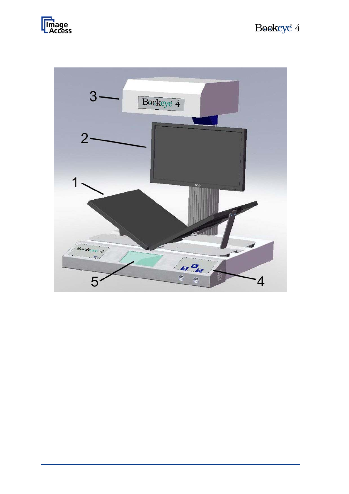
Picture 1: Elements of the Bookeye 4
Some of the major components of the Bookeye® 4 scanner have been identified in the
above picture. These components are referenced in this operation manual.
The Bookeye® 4 scanner main hardware elements are:
1. V-shaped book cradle. Can be fixed in “V” position or lie in a flat position. The
book cradle plates can be opened to a maximum distance of approx. 325 mm
(12.8 inches).
2. TFT flat screen. Shows the scanned image. All modifications of an image, e.g.
color mode or scan size, will be displayed immediately on the TFT flat screen.
3. Camera head. The camera head contains the camera, the red light cross-hair
laser, and the lamps.
4. Front panel. On the front panel, two USB ports, the on/off switch and the touch
panel can be found.
5. Touch panel: The touch panel shows all menus used to set up and control the
Bookeye® 4 scanner.
Page 14 Operation Manual
Page 15
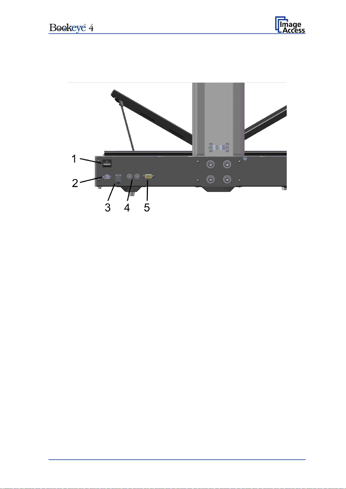
A.2.1 Connectors on the Rear Side
For easy orientation, the connectors found on the rear side of the scanner are depicted in
the following picture and described below.
Picture 2: Connectors on the rear side
1. Main power switch. Set the main power switch to position I to set the Bookeye 4
scanner to stand-by mode.
2. Connector for external power supply.
3. Network connector. Insert a network cable for access to the scanner via the
integrated Scan2Net user interface.
4. Two foot pedal connectors.
5. Serial port.
A.2.2 Content on Delivery
The scanner is delivered in a wooden transport box. The transport box also contains
A folder with four CSTT-1 reference targets
Two White Reference targets 500 x 120 mm
A foot pedal switch
Patch cable, length 3 meters.
Recovery Key with instructions
External power supply with power cable
Please note: Keep the wooden transport box for future use! If the scanner needs to be
returned to depot, it must be sent back in the original transport box to
avoid transport damages.
Operation Manual Page 15
Page 16

A.2.3 Connecting the Power Source
The connector for the external power supply and the main power switch connector are
both located at the right side of the back of the document bed.
Important: Before connecting to the power source, check the following:
The wall outlet for the external power supply is in perfect condition and
properly grounded.
The power cable of the external power supply is not damaged in any way.
The wall outlet fuse has the correct electrical dimensions. Refer to the
technical specification chart for detailed information.
After the power source is connected and the main power switch is turned on, the symbol
in the on/off button lights up.
Red illumination of the button signals that the Bookeye 4 is in stand-by mode.
A.2.4 Starting the Bookeye 4
Push the red illuminated on/off button to start the scanner.
The button illumination changes to blue.
The scanner starts with self-test routines and verifies all system components. A status
message will be displayed on the TFT flat screen and on the touch panel.
At the end of the start-up sequence, the touch panel displays the start screen.
A.2.5 Switching the Bookeye 4 to stand-by mode
Press and hold the on/off button for at least three seconds. While pressing the button, a
“click” sound is audible.
The content of the TFT flat screen and the touch panel changes and displays the
message: Going to shut down now …
Page 16 Operation Manual
Page 17

A.3 Device Location
A.3.1 Environment
Choose a location that complies with the temperature and humidity specifications.
For detailed information on these specifications, see the chapter D.2.
A.3.2 Ambient Light
The Bookeye 4’s location should have a controlled ambient light situation. The light
scenarios should avoid direct sunlight or spot light from light beams.
Also light sources that cause sharp shadows on the document on the book cradles or high
levels of ambient light could influence the scan result negative.
The Bookeye 4 scanner is an open system with a built-in high quality light source. Open
system means that the ambient light is added to the light seen by the camera.
Summary of a recommended location for a Bookeye 4 scanner:
The location is not exposed to daylight.
It is evenly illuminated from the ceiling with fluorescent lamps with electronic ballasts.
The light intensity measured on the book cradles should be approximately 300 lux.
The light should not cause any shadows; therefore the variation of the intensity across
the scan area should be kept below 20%.
If the fluorescent lamps are powered by non-electronic ballasts, they will produce a flicker
twice the frequency of the main power supply (100Hz or 120Hz). If the intensity of this
light becomes too high, vertical stripes of even distances of approx. 8-12 pixels will be
visible on the scan.
Direct sunlight will vary over the day and will result in overexposed images. Sunlight can
also produce distinct shadows.
Light beams from spotlights will also produce distinct shadows. In most cases, they emit a
high level of infrared light. Infrared light is not visible to the human eye but to the camera.
The light source of the Bookeye® 4 scanner itself has no infrared content at all, which
means that the scanner does not have an image quality degrading infrared filter. Too
much infrared content will result in overexposure.
The Bookeye® 4 scanner has an integrated “White Balance” function. This function will
compensate ambient light influences. A “White Balance” calibration is recommended
when the light scenario has changed.
For details about the ”White Balance” calibration, see chapter B.6.1 White Balance.
Operation Manual Page 17
Page 18
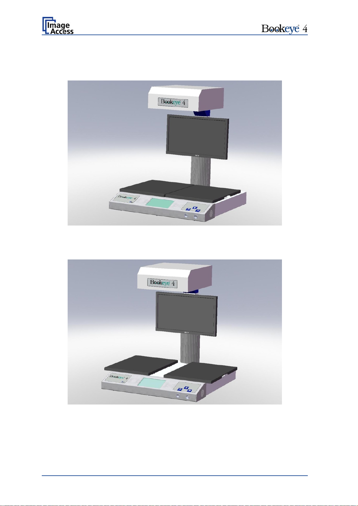
A.4 Book Cradles
The book cradles on the Bookeye 4 can be set in different positions.
Picture 3: Book cradles flat and closed
The plates of the book cradle can be slid apart from each other. The maximum distance
between the book cradles is approximately 325 mm (12.8 inch).
Picture 4: Book cradles flat and opened
This allows placing books or other documents with a large spine in a position more
beneficial for the book spine.
Page 18 Operation Manual
Page 19
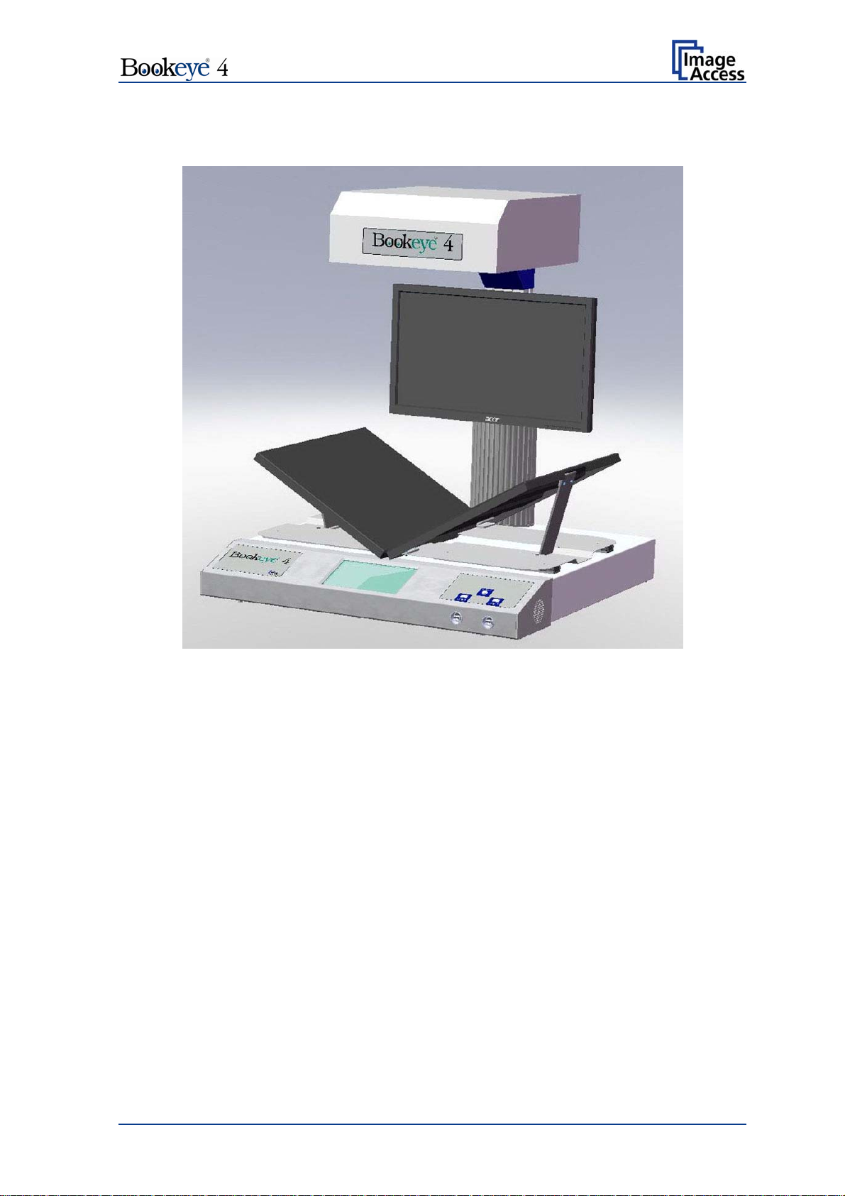
The plates can also be set in the “V” position, with an opening angle of 120 degrees. This
is recommended for very delicate, old documents.
Picture 5: Book cradles in the "V" position
When the book cradles are lifted to the “V” position, they are held by a supporting leg on
each side.
Operation Manual Page 19
Page 20
B Software
The Bookeye 4 scanner can be controlled in two ways.
via the integrated touch panel.
via a standard browser and the Scan2Net software interface.
Please note: All screenshots are taken from a fully equipped device with all options
and functions activated. Depending on the selected mode, the menus
displayed on the screen can vary.
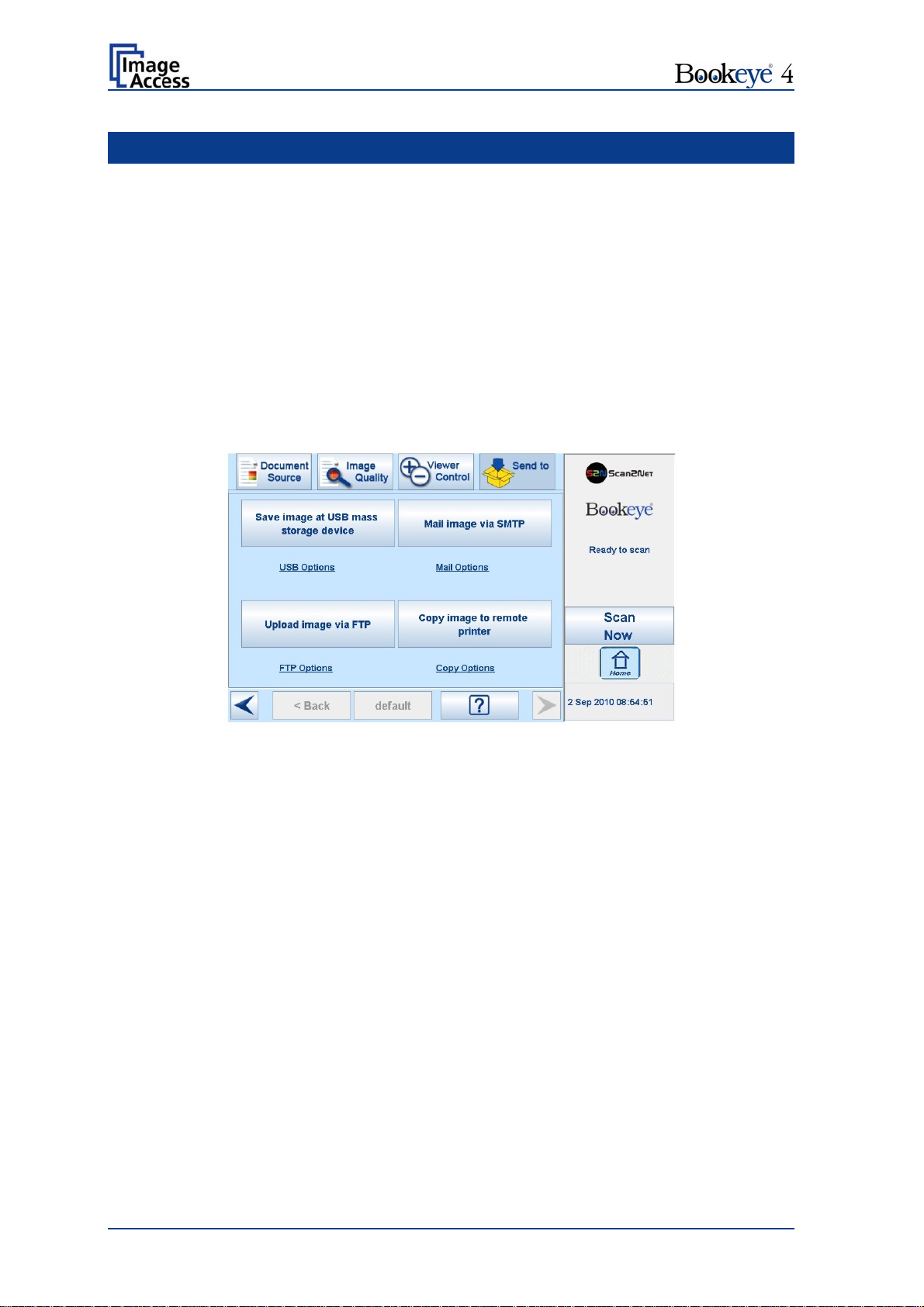
B.1 Touch Panel – Start Screen (Send to)
When the Bookeye 4 scanner starts from stand-by mode and finishes the startup
procedure, the touch panel displays the start screen.
Picture 6: Start screen after start-up
Pressing the Scan Now button starts the scan sequence.
When pressing one of the four buttons in the main part of the touch panel, the scanned
image will be directed to the target as defined on the respective button.
By touching the text below each button, the options of the selection will be displayed.
Chapter B.5 provides detailed information on the available parameters.
Page 20 Operation Manual
Page 21
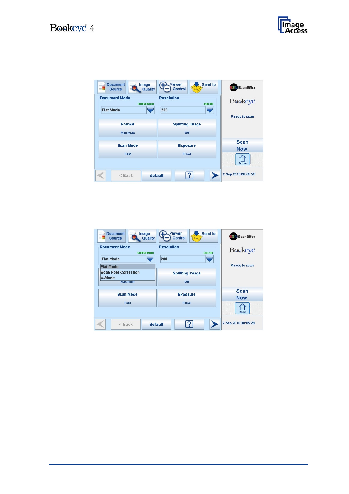
B.2 Touch Panel – Document Source
The Document Source screen allows selecting from a wide range of scan parameters.
Picture 7: Document Source screen
B.2.1 Document Mode
The Document Mode setting defines the focusing method when scanning documents.
Picture 8: List of Document Modes
Flat Mode: The focus value will be set in dependence of the document height.
This focus value will be used for the complete scan area.
Book Fold Correction: Recommended method for scanning books. The book binding
curvature will be compensated and flattened out. The focus will be
set depending on the form of the book and its curvature.
V-Mode: To be used when the book cradle is opened in the “V”position.
The focus will be dynamically set dependent on the “V” position of
the book cradle.
Operation Manual Page 21
Page 22
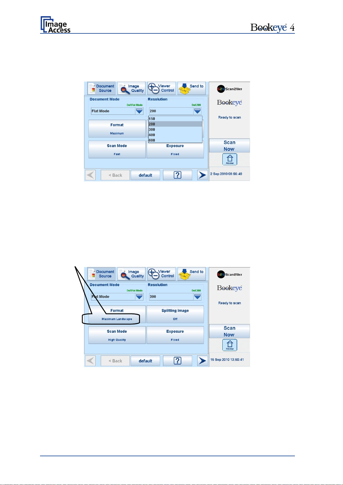
B.2.2 Resolution
The Resolution setting allows selecting a resolution from a list of resolution values
supported by the Bookeye 4 scanner.
Picture 9: List of Resolutions
The list can be opened by pressing the blue arrow symbol beside the currently selected
value. Select a new resolution by touching the preferred value.
B.2.3 Format
The Format button allows you to select the scan area size.
Depending on the Document Mode selected, the available formats will vary.
The bottom line of the button Format shows the current format setting.
Picture 10: Selectors for Format settings
The following subchapters describe the available combinations of document mode and
format.
Page 22 Operation Manual
Page 23
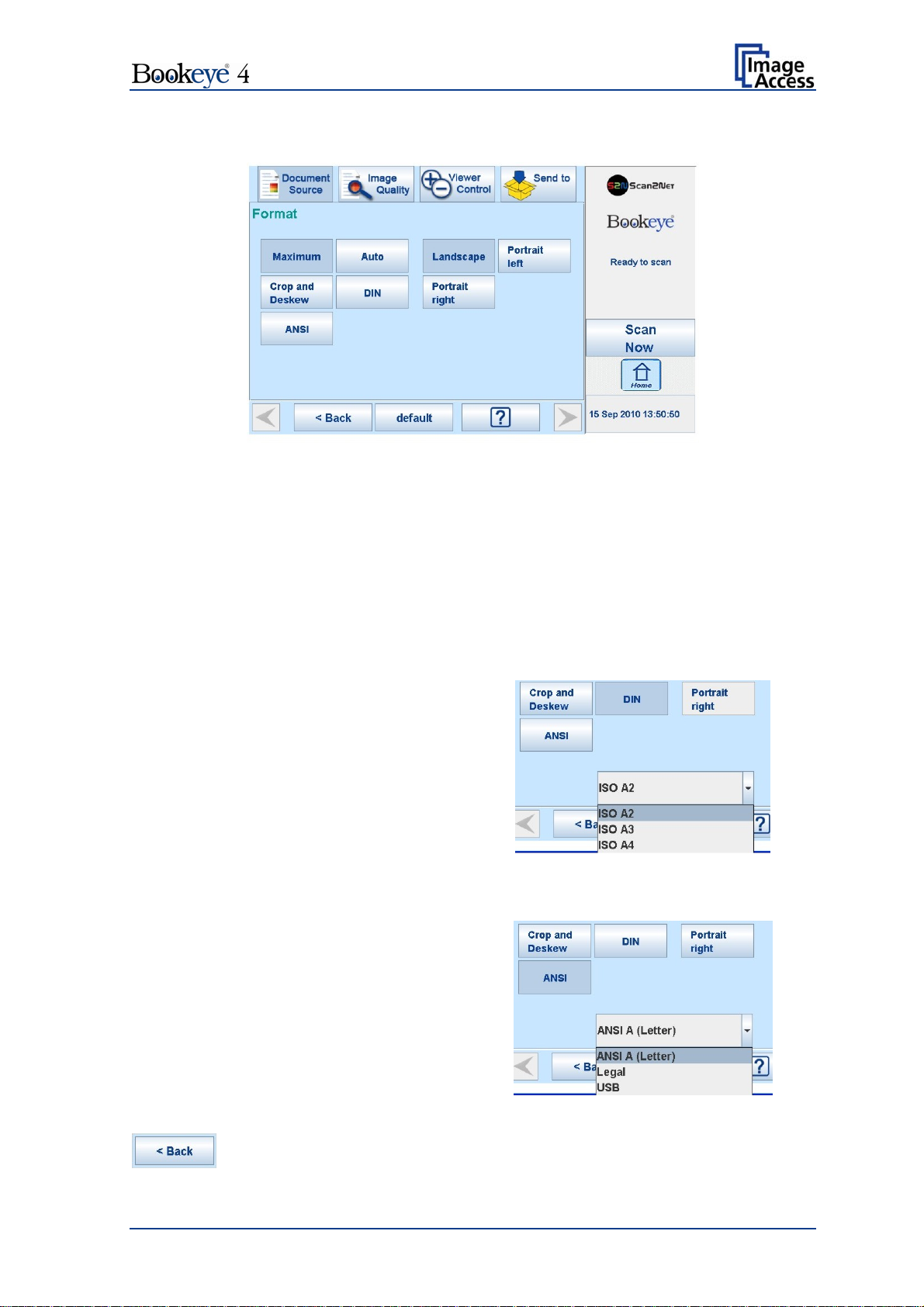
B.2.3.1 Flat Mode Formats
Picture 11: Flat Mode Formats
Maximum: Selects the maximum scan area for the scan and displays it in the
image.
Auto: The complete scan area will be scanned but in the image, the black
border will be removed. The resulting image shows only the
document with the smallest possible margin.
Crop and Deskew: If a document is not placed perfectly aligned horizontally and
vertically, this function will correct the alignment.
DIN: When selecting DIN, an additional
small window opens. It shows the available
DIN paper sizes.
Landscape, Portrait left or Portrait right
defines the orientation of the scan area.
Picture 12: DIN formats
ANSI: When selecting ANSI, an additional
small window opens. It shows the available
ANSI paper sizes.
Landscape, Portrait left or Portrait right
defines the orientation of the scan area.
Picture 13: ANSI formats
Press this button to return from a submenu to the main menu.
Operation Manual Page 23
Page 24
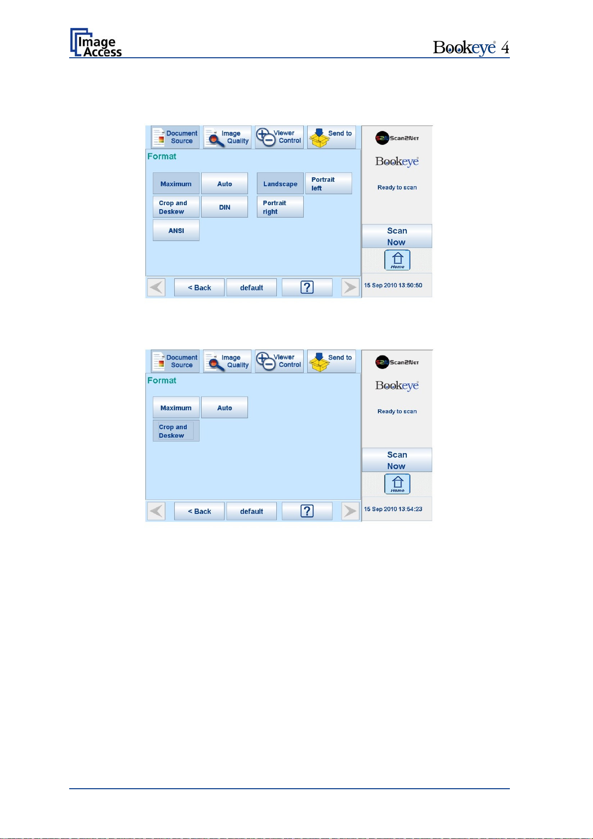
B.2.3.2 Book Fold Correction Formats
The formats available are similar to the formats available in Flat Mode.
Picture 14: Book Fold Correction Formats
B.2.3.3 V-Mode Formats
Picture 15: V-Mode Formats
Three formats are available in V-Mode.
Maximum: Selects the maximum scan area for the scan and displays it in the
image.
Auto: The complete scan area will be scanned but in the image, the black
border will be removed. The resulting image shows only the
document with the smallest possible margin.
Crop and Deskew: If a document is not placed perfectly aligned horizontally and
vertically, this function will correct the alignment.
Page 24 Operation Manual
Page 25
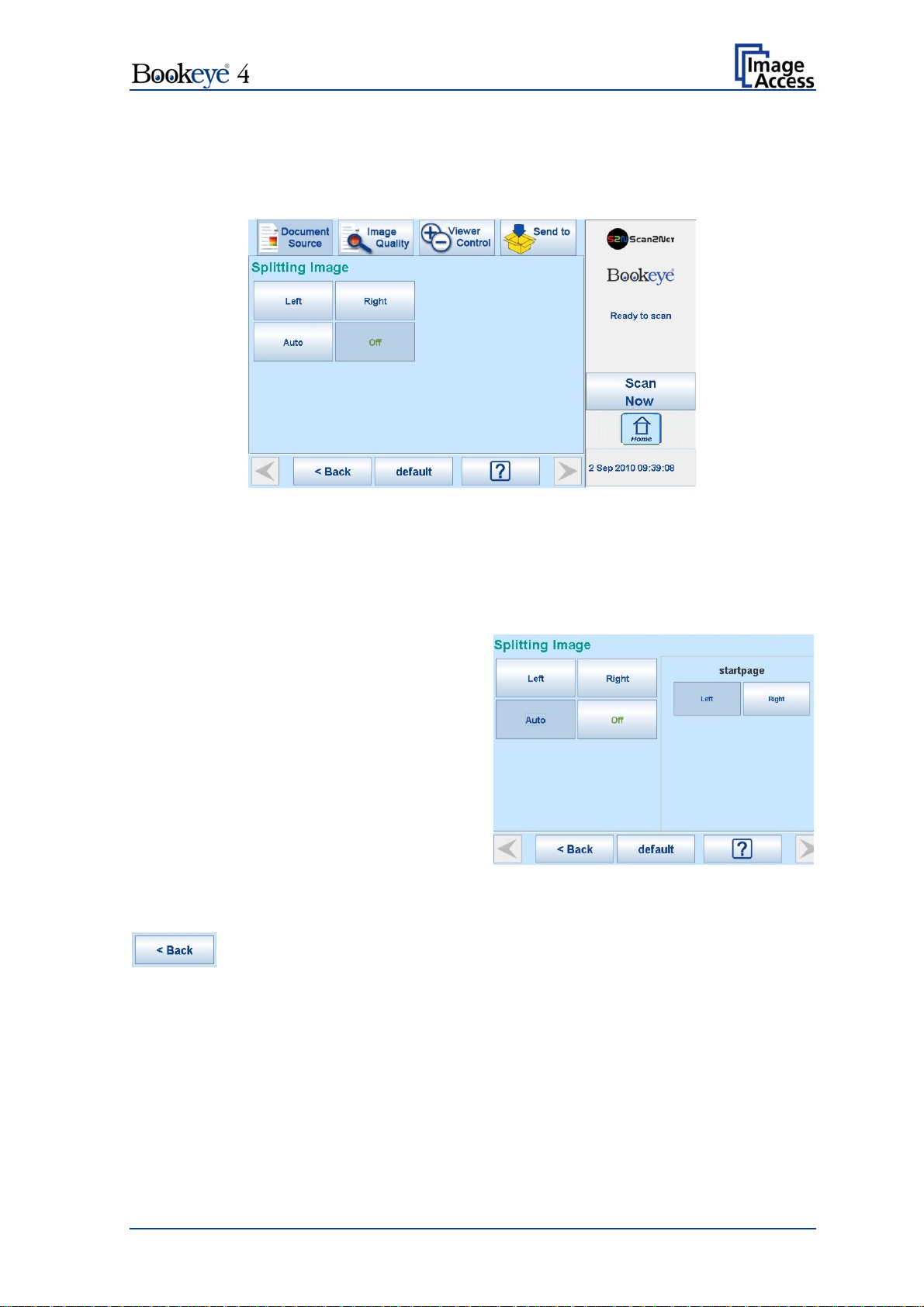
B.2.4 Splitting Image
The button Splitting Image is used to select splitting the document scanned for the output
images.
Picture 16: Splitting Image
Left: The complete document will be scanned. Only the left half of the document will
be displayed.
Right: The complete document will be scanned. Only the right half of the document will
be displayed.
Auto: The complete document will
be scanned. The image will be
divided into two symmetrical parts.
Both parts will be displayed
successively as separate images.
If selecting Auto, an additional
selector opens. Here the page that
will be displayed first can be
selected as a start page.
Picture 17: Start page selector
Press this button to return from a submenu to the main menu.
Operation Manual Page 25
Page 26
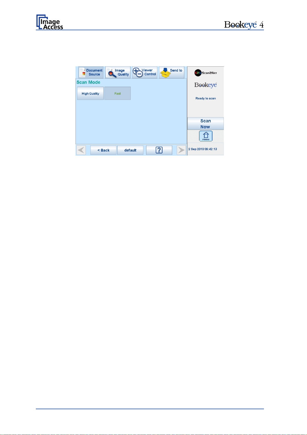
B.2.5 Scan Mode
The Scan Mode screen allows the user to select from two possible scan modes.
Picture 18: Available Scan Modes
High Quality scans with reduced scanning speed but improved scanning quality.
Fast scans with normal speed, depending on the selected scan resolution.
Page 26 Operation Manual
Page 27

B.2.6 Exposure
The Exposure screen allows selecting the functions Black Cut and Auto.
Picture 19: Exposure Modes
When Black Cut or Auto is selected a numeric key pad opens.
Picture 20: Numeric key pad to set threshold value
Black Cut
0 (zero) to 100
Sets the threshold for black. All pixel values found in the image below
the selected value are set to solid black.
Result: The image contrast is improved.
Auto
0 (zero) to 100
Sets the threshold for black and activates the automatic exposure
control.
This function analyzes the image and detects the brightest and the
darkest area. The detected brightness range is expanded to the
maximum range of the scanner. Otherwise all values below the
threshold are defined as “black”.
Result: Automatic contrast control and the image contrast is improved.
To set a new value, touch in the line of the displayed value and erase the value with the
DEL button.
Enter the new value with the key pad and touch Send to send the new value.
Operation Manual Page 27
Page 28
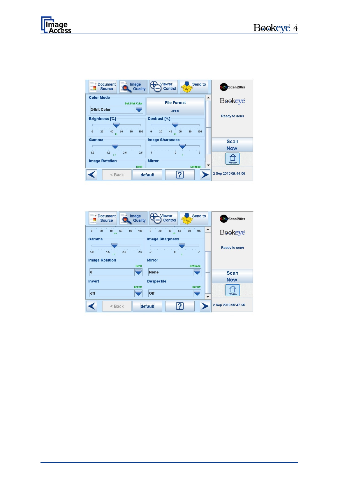
B.3 Touch Panel – Image Quality
The Image Quality screen allows setting a wide range of image quality parameters.
Picture 21: Image Quality 1
In color mode Binary, the menu items will be extended with Invert and Despeckle.
Picture 22: Image Quality 2
Page 28 Operation Manual
Page 29
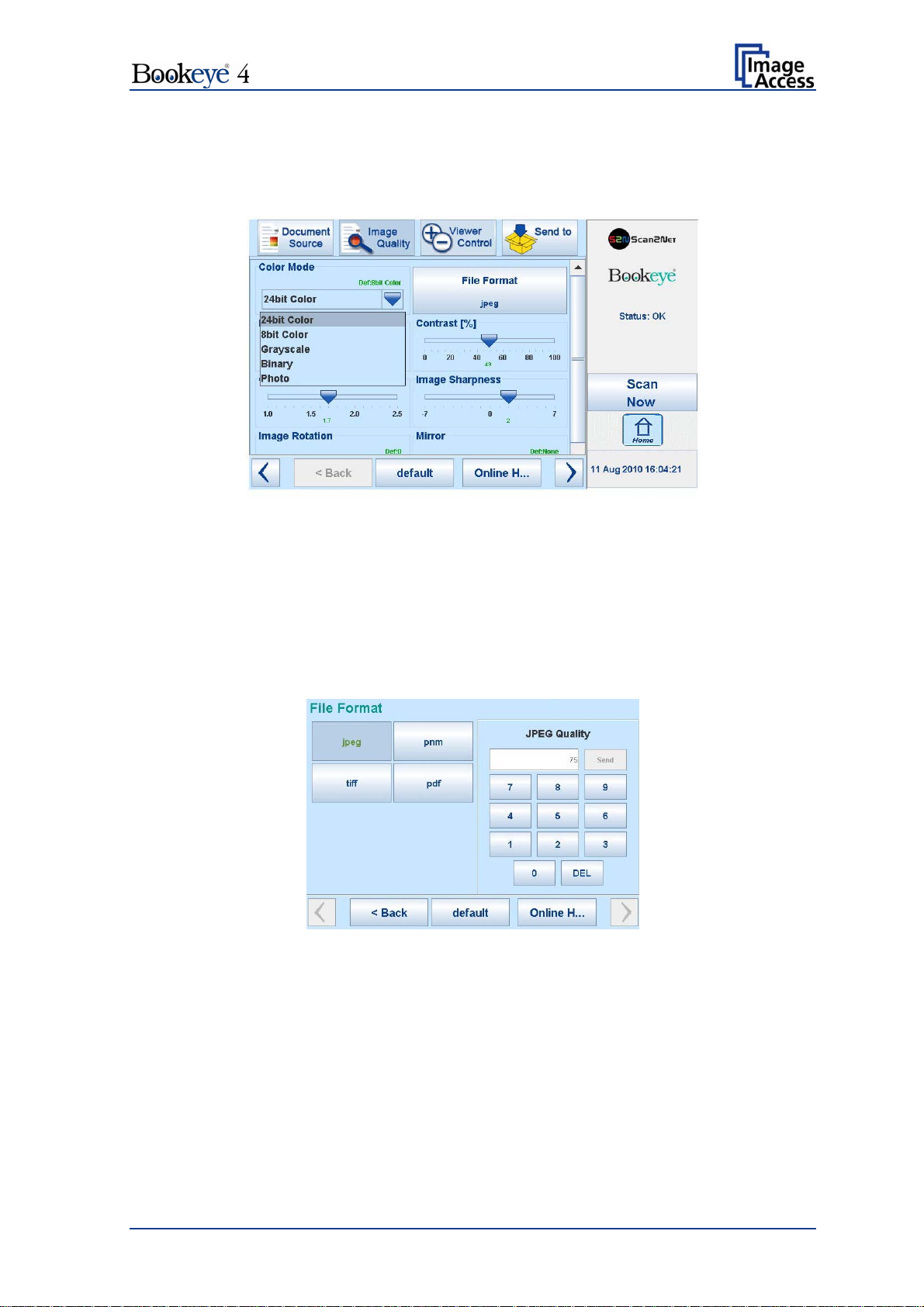
B.3.1 Color Mode
Pressing the selection arrow of the Color Mode section opens the list of available color
modes.
Picture 23: List of Color Modes
Pressing the title of the desired color mode selects the mode and closes the list.
Picture 23 shows the available color modes.
B.3.2 File Format
Press the File Format button to select a file format for the images.
B.3.2.1 JPEG
Picture 24: Submenu File Format “jpeg”
Depending on the file format selected, some additional parameters will be displayed.
With the jpeg file format, a value for the image quality can be entered by the numeric key
pad.
This value determines the compromise between quality and compression rate. A higher
quality factor produces larger files. The default setting of 75 is a good compromise for
most documents.
Operation Manual Page 29
Page 30
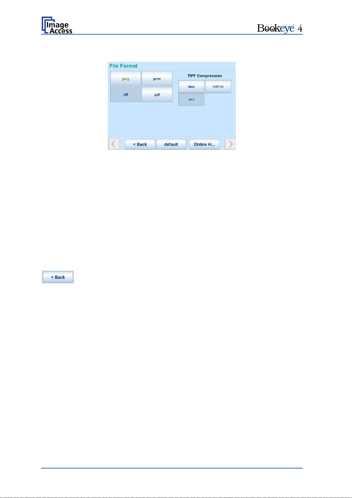
B.3.2.2 TIFF
Picture 25: Submenu File Format TIFF
With the TIFF file format, the compression method of the file can be selected with the
TIFF Compression buttons.
B.3.2.3 PNM
With the PNM file format, no additional parameters are available.
B.3.2.4 PDF
With the PDF file format, the same compression methods are available as with the TIFF
format (see picture above).
Press this button to return from a submenu to the main menu.
Page 30 Operation Manual
Page 31
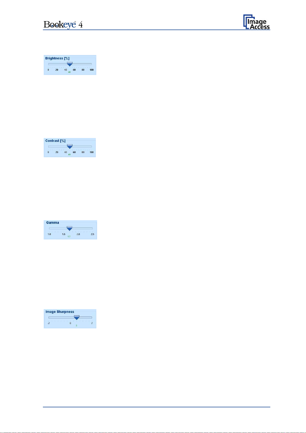
B.3.3 Brightness
Picture 26: Brightness slider
The Brightness slider defines the resulting brightness in the image. Lower brightness
values result in darker images, higher values result in brighter images.
Values close to 0% or to 100% may result in unwanted artifacts.
Move the slider indicator to the desired position to set the value.
B.3.4 Contrast
Picture 27: Contrast slider
The Contrast slider defines the contrast in the image. Lower contrast values result in
“smoother” images, higher values show more details and the images become “crisper”.
Values close to 0% or to 100% may result in unwanted artifacts.
Move the slider indicator to the desired position to set the value.
B.3.5 Gamma
Picture 28: Gamma slider
The Gamma slider defines the gamma correction directly inside the camera electronics. A
value of 1.7 is a good approximation for most documents.
Higher gamma values show more details in dark areas and compress bright areas of the
image.
Move the slider indicator to the desired position to set the value.
B.3.6 Image Sharpness
Picture 29: Image Sharpness
The Image Sharpness slider invokes an advanced automatic sharpening algorithm which
sharpens the image before any other operation is performed.
The value “zero” disables the function. Very high values may produce artifacts depending
on the type of document.
Move the slider indicator to the desired position to set the value.
Operation Manual Page 31
Page 32

B.3.7 Image Rotation
Picture 30: Image Rotation
The value selected from the list defines the rotation of the image in a clockwise direction.
The image will be rotated directly after scanning and before display
B.3.8 Mirror
Picture 31: Mirror
This control mirrors the image along the selected mirror axis.
Using this setting can be helpful if scanning transparencies from the back.
B.3.9 Invert
Picture 32: Invert
This control is only available with the color modes Binary and Photo.
B.3.10 Despeckle
Picture 33: Despeckle
(Only available in Binary color mode)
Available modes are 4x4p and Off.
Page 32 Operation Manual
Page 33

(1)
B.4 Touch Panel – Viewer Control
The Viewer Control screen allows the operator to control and modify the image on the
TFT flat screen.
Picture 34: Viewer Control screen
The rectangle (1) represents for the TFT flat screen.
If the displayed image overlaps the dimension of the TFT flat screen, it can be moved by
touching the arrow buttons on the upper and lower, left and right margin of the rectangle.
Rotates the image on
Every touch on the button rotates the image by an angle of 90 degrees.
Adapts the complete ima
Scales the
The result depends on the scaling factor of the graphic interface.
Displays the image on
depending on the resolution selected for scanning.
image on the screen to the real size of the source document.
the TFT flat screen in clockwise direction.
ge, matching the size of the TFT flat screen.
the screen with its genuine dimensions (100%),
Operation Manual Page 33
Page 34

B.5 Touch Panel – Send to
After the scanner has started, this screen is displayed on the touch panel by default. It
allows the operator to select the output option for the scanned images.
Picture 35: "Send to" screen
B.5.1 USB Options
Two USB sticks can be connected to the Bookeye 4 scanner at the connectors on the
front.
After touching USB Options, the content of the USB stick will be displayed. While the
directory of the stick is displayed, the LED indicator of the respective connector is
continuously illuminated.
Touch Ok or Cancel to stop displaying the directory of the USB stick.
When data is transferred between the USB stick and the scanner the LED indicator blinks.
Note: When the blue indicator LED stops blinking, data transfer may still be in
progress. Before unplugging the USB stick, wait a few seconds to avoid loss of
data.
Page 34 Operation Manual
Page 35

3
B.5.2 Mail Options
Touch Mail Options to switch to the screen showing the preset email configurations.
Three preset configurations can be stored and activated with the buttons Mail 1 to Mail 3.
Picture 36: Parameters of Mail Options
To change an entry, touch the respective line.
The screen changes to an alphanumeric keyboard.
1
2
Picture 37: Alphanumeric keyboard
1: Use the arrow keys to position the cursor in the line.
2: Use this key to delete characters.
3: Use this button to switch from alphanumeric keyboard to numeric keyboard.
Touch the Ok button to confirm the new entry.
Touch the Cancel button to discard the new or changed value.
Operation Manual Page 35
Page 36

B.5.3 FTP Options
Touch FTP Options to switch to the screen with the preset FTP server configurations.
Three preset FTP servers can be stored and activated with the buttons FTP 1 to FTP 3.
Picture 38: Parameters of FTP Options
From the touch panel, only the entry for Name can be changed.
All other parameters must be changed from the Scan2Net user interface.
For detailed information about changing the parameters see chapter C.3.5.
Page 36 Operation Manual
Page 37

B.5.4 Copy Options
Touch Copy Options to switch to the screen with the preset copy option configurations.
Three preset options can be stored and activated with the buttons Copy1 to Copy3.
Picture 39: Parameters of Copy Options
Currently, the parameters can only be changed from the Scan2Net user interface.
For detailed information about changing the parameters see chapter C.3.5.
Operation Manual Page 37
Page 38

B.6 Setup and Adjustments
The Bookeye 4 allows some adjustments to be made directly via the touch screen, e.g.
auto focus setting and White Balance calibration.
Furthermore, the IP address can be configured and other user settings can be defined.
To enter the setup menu, touch the touch panel at the date and time section ten times
successively.
The screen will change and show the first screen of the setup menus.
Touch here 10x
Picture 40: Setup menu start screen
B.6.1 White Balance
The first menu item of the setup menus is the White Balance screen.
Whenever it is necessary to perform a White Balance calibration, the touch panel shows
how to position the reference target and the book cradles for optimal calibration.
For the White Balance calibration, close the book cradles and place the reference target
as shown.
Touch the Calibrate button.
The calibration sequence will be executed. It takes approximately 40 seconds.
At the end of the calibration sequence, the results will be displayed on the touch panel.
Page 38 Operation Manual
Page 39

B.6.2 IP Address
Picture 41: IP Address mask
To change or define the numeric values, touch the number in the respective line of IP
address, gateway or netmask.
Touch the line at the desired position to move the “cursor”.
To delete a digit, place the cursor at the right side of the digit and press the “<=” button. It
will always be deleted from right to left.
Use the numeric keypad in order to enter digits.
Set network settings saves the new or modified values when pressed.
Reset network settings sets all network parameters to default value when pressed.
Operation Manual Page 39
Page 40

B.6.3 Time and Date
Picture 42: Time and date
To change time or date value, touch the value in the respective line.
Touch the line at the desired position to move the “cursor”.
To delete a digit, place the cursor at the right side of the digit and press the “<=” button. It
will always be deleted from right to left.
Use the numeric keypad in order to enter digits.
Store time and date saves the modified values when pressed.
Reset time and date sets the values to default values when pressed.
Page 40 Operation Manual
Page 41

B.6.4 User Settings
Picture 43: User Settings menu
The User Settings menu allows defining the touch panel menu parameters.
Language selector: The touch panel menu language can be selected by touching the
selection arrow. A list opens, showing the available languages.
Touching the name of the desired language completes the
selection.
Please note: The language of the setup menu always remains in
English.
Default: Sets all settings of the scanner to default values.
Motor init: Only to be used by trained technicians for service purposes.
Easy: Reduces the available menu items in the touch panel to the
minimum required functions.
Custom Mode: Allows definition of the available menu items through a special
technician’s application.
Expert Mode: Shows all available menu items in the touch panel menus.
Operation Manual Page 41
Page 42
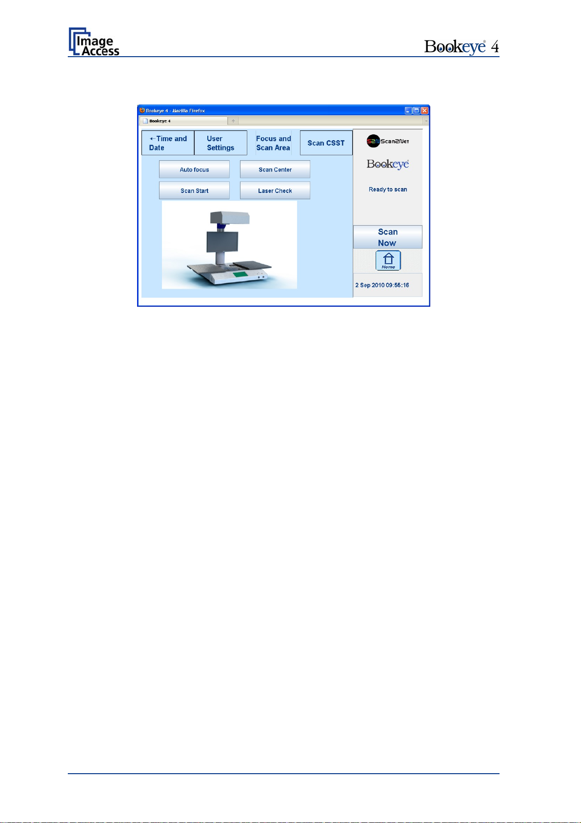
B.6.5 Focus and Scan Area
Picture 44: Focus and Scan Area menu
The Focus and Scan Area menu contains four buttons for measurement purposes.
When touching one of the four buttons, the picture on the touch panel changes. It shows –
depending on the function selected – how the book cradles and the reference target must
be positioned.
Auto focus: The book cradles must be opened to make the center foil on the
device body visible.
Touching the Next button starts the measurement. The lamps light
up and measurement will take approximately 20 seconds. Finally,
the touch panel displays the results.
Scan Start: The book cradles must be opened to make the center foil on the
device body visible.
Touching the Next button starts the measurement. The lamps light
up and measurement will take approximately 20 seconds. Finally,
the touch panel displays the results.
Scan Center: The book cradles must be closed and free of any documents.
Touching the Next button starts the measurement. The lamps light
up and measurement will take approximately 20 seconds. Finally,
the touch panel displays the results.
Laser Check: The book cradles must be closed. The White Reference target must
be placed on the book cradles as shown in the picture.
Touching the Next button starts the measurement. The laser will be
switched off and on during the measurement. Finally, the touch
panel displays the results.
Touching Back returns to the Focus and Scan Area menu.
Page 42 Operation Manual
Page 43

B.6.6 Scan CSTT
Picture 45: Scan CSTT screen
The picture on the touch panel changes and shows how the CSTT test targets must be
placed on the book cradles.
Touching the Scan CSTT button starts the measurement. The test targets will be
scanned.
Please note: This function has not been finalized yet. Additional information will follow.
Operation Manual Page 43
Page 44

C Software Operation
Essentially, the scanner is a web server and comes with its own HTML based user
interface. To access a Scan2Net scanner, any standard web browser can be used.
A basic requirement before working with the integrated user interface is to configure the
browser as follows:
Force the browser to reload the page content every time directly from the scanner and
not to load from the cache memory.
Enter the scanner’s IP address in the exception list.
C.1 The Integrated User Interface
Start your browser.
Enter the IP address of the scanner. The default IP address of the scanner: 192.168.1.50
The following start screen of the integrated user interface will be displayed.
Picture 46: User interface start screen
Launch Scan Application switches to the main screen. Detailed information will be found
starting in chapter C.2.
Information gives a short summary of the device parameters. Information will be found
in chapter C.4.
Page 44 Operation Manual
Page 45
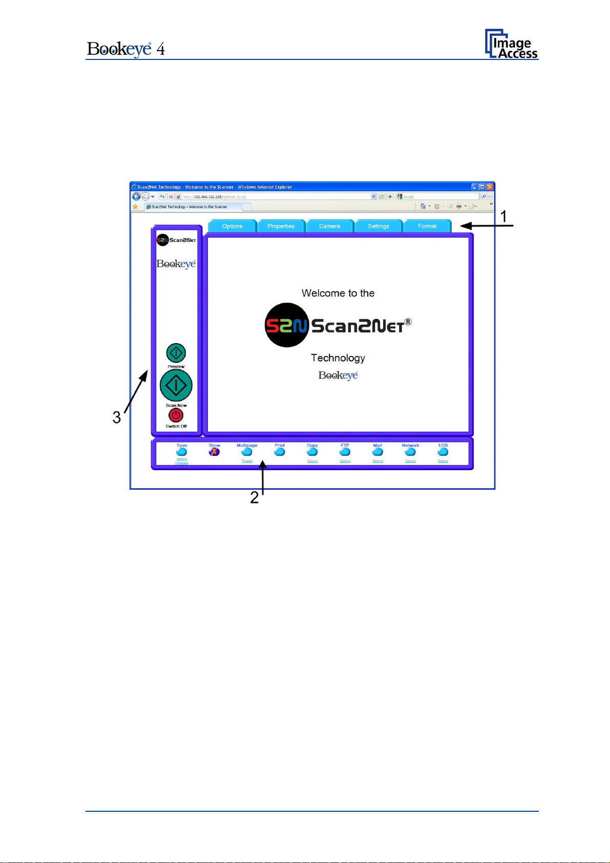
C.2 The Main Screen
After launching the scan application, the main screen of the integrated user interface will
open. The main screen is structured in three parts. Switching between the sections is
done with a mouse click.
Picture 47: Main screen
1: The menu bar of the large frame on the upper right part has five menu items:
Options
Properties
Camera
Settings
Format
Click at a menu item to select and set parameters of the scanner.
Operation Manual Page 45
Page 46
2: The control buttons in the lower part of the screen control the output modes.
When selecting Save the scanned image will not be displayed. Instead of the
displayed image, a box opens in which the desired directory can be set.
By default, the output mode Show is selected. After clicking the button Preview or the
button Scan Now, a window opens and shows the image.
Selecting Multipage allows the operator to create a multipage image. The scan result
will not be displayed. Clicking on Finalize
opens an additional window and shows the
images.
Selecting Print will display the scanned image in a second window and direct the
scanned image to locally available printers.
Selecting Copy prints directly to a previously installed network printer.
Selecting FTP scans directly to a FTP server.
Selecting Mail sends the scanned image directly to a previously defined e-mail
address.
Selecting Network uploads the scanned image directly to a previously defined
workstation in the network.
Selecting USB stores the scanned image on a USB stick. USB sticks can be
connected to the scanner at the two connectors at the front side.
3: The frame on the left side shows the buttons for preview scan (Preview) and main
scan (Scan Now).
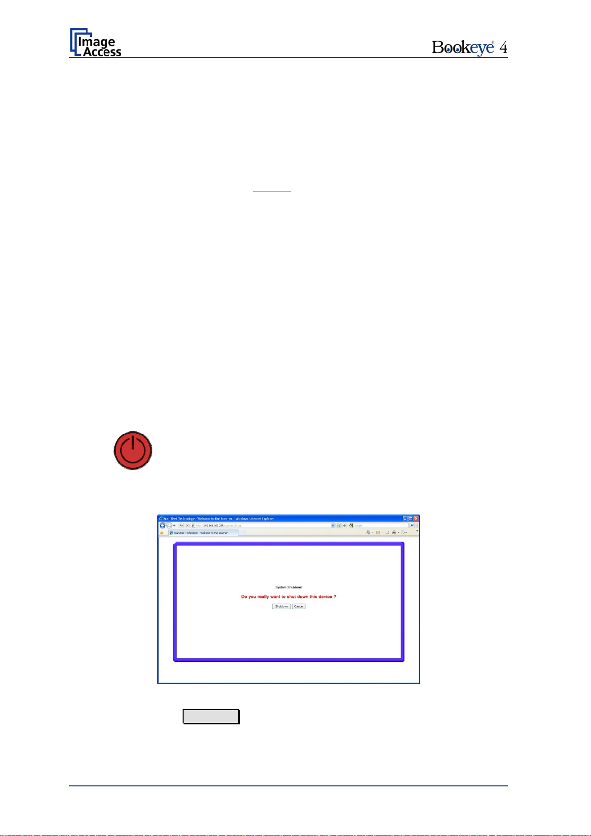
Pressing this button switches the scanner off.
If the red button is pressed, the following window will appear.
Picture 48: Shutdown confirmation
Click on the button Shutdown and the scanner switches off.
Page 46 Operation Manual
Page 47
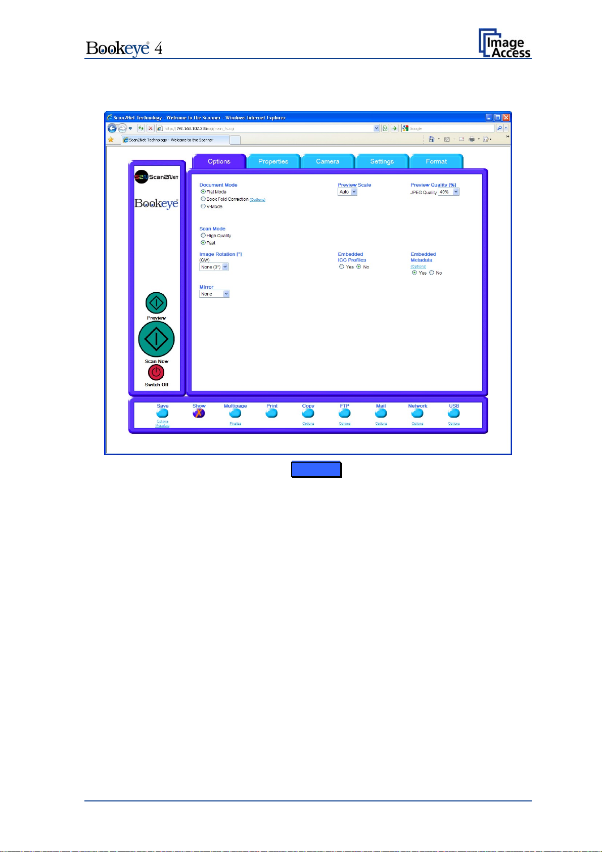
C.2.1 The Options Screen
Picture 49: Options screen
Document Mode
The Document Mode allows the user to select between different types of documents:
In Flat Mode, the document is treated as flat, i.e. with a fixed focus setting, regardless
of the actual shape of the document. This mode avoids out of focus problems when
scanning three dimensional objects that cannot be described as folders or books.
In the Book Fold Correction mode, the focus follows the surface of a book while the
document is scanned. All geometric distortions are compensated. It is essential that the
book be aligned straight to the laser line for optimal results. More details on the book
fold correction can be specified in the
(Options) dialog (see chapter C.2.1.1).
The V-Mode should be used when the book cradle is opened in the “V”-position. The
focus will dynamically be set based on the “V” position of the book cradle.
Operation Manual Page 47
Page 48

Scan Mode
The Scan Mode allows the user to select between High Quality with a reduced scanning
speed, or Fast with normal scanning speed.
Image Rotation
Image Rotation can be a degree of rotation of either 90°, 180°, 270° or none. The angle
is defined in the clockwise direction.
Mirror
The Mirror setting allows the user to select between mirroring the scanned image along
the Horizontal axis or along the Vertical axis. Selecting None disables this function.
Preview Scale
The Preview Scale value sets the size of the preview image. If set to Auto the function
will perform a best fit before the image is displayed on the screen.
Preview Quality [%]
The Preview Quality [%] sets the JPEG quality of the preview image.
Embedded ICC
The Embedded ICC switch is either Yes or No.
Embedded Metadata
The Embedded Metadata switch is either Yes or No. More details can be specified in the
(Options) dialog (see chapter C.2.1.2).
Page 48 Operation Manual
Page 49

C.2.1.1 Book Fold Options
Clicking on (Options) opens an additional window
for setting the book fold parameters.
Picture 50: Book Fold Option screen
It allows set
ting the value for the margins, the left
and the right center position as well as the
threshold value.
The unit of measurement is “mil”. This unit of
measurement is defined as 1000 mil = 1 inch.
The Surface Propertie s slider allows the user to
specify corrections for different surfaces, from
matte to glossy.
The Retouch Bookfold switch is either auto,
manual or off. If auto is selected, the width of the
book fold area will be detected automatically and
filled. If manual is selected the sliders for
Left Center Position and Right Center Position
define the width of the filled area.
The Retouch Pattern switch is either auto, black
or white. If auto is selected the pattern matches
with the pattern in the book fold area, otherwise it
is black or white.
Operation Manual Page 49
Page 50

C.2.1.2 Embedded Meta Data
This function is used in conjunction with the file
formats JPEG, TIFF or PDF.
It enables the operator to include a set of
XMP/RDF compliant document metadata in the
file header.
Select Yes or No. Go to (Options) to define a
set of XMP/RDF compliant metadata. The
configuration window will pop up.
Picture 51: Metadata screen
Metadata Description
Author The name or organization creating the document or the
copyright owner of the document.
Title A short title for the scanned document.
Subject Abstract of the document.
Copyright Marker Select if the scanned document is copyright protected.
Copyright Information The copyright message can be entered here. This
message will be only embedded in the scanned document
if the copyright marker is set to “yes”.
URL of extended
Copyright Information
Keywords
(comma separated list)
An external URL which shows a detailed copyright
message.
A list of comma separated keywords which describe the
content of the document.
Note: Each change to an entry field is transferred to the scanner immediately.
Page 50 Operation Manual
Page 51

C.2.2 The Properties Screen
Picture 52: Properties screen
Color Mode
The Color Mode allows the user to select one of the available color modes. The color
modes are:
24bit Color, 8bit Color, Grayscale, Binary or Photo.
To select a color mode first click on the selection
arrow, then select a mode from the list.
Operation Manual Page 51
Page 52

File Format
File Format defines the file format used to store a scanned document.
Note: There are some interdependencies between Color Mode and File Format. It is
not possible to combine all color modes with all file formats. For example, an
image scanned in “24bit Color” cannot be stored in TIFF file format with
TIGG G4 compression.
Depending upon the selected file format, the control beside it can vary:
Example:
Color Mode 8bit Color, File Format TIFF
TIFF Compression is d
isplayed
additionally.
Picture 53: 8bit Color
JPEG Quality [%]
The JPEG Quality [%] control determines the compromise between quality and
compression rate. A higher quality factor produces larger files. The default setting of 75 is
a good compromise for most documents.
Page 52 Operation Manual
Page 53
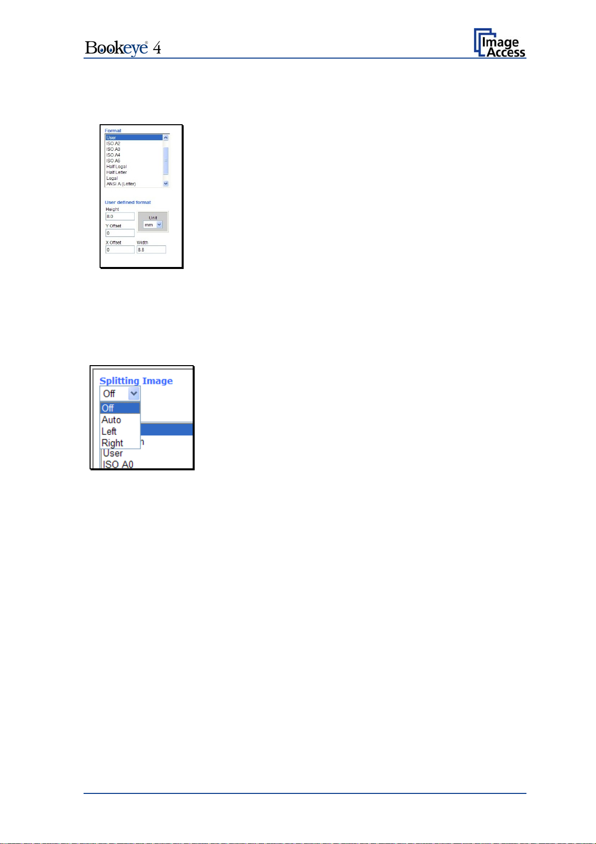
Format
The Format list offers various standard paper formats.
With Auto
the scanner scans the complete document area,
removes the black border around the document and crops it to
its real size and displays the image.
If Maximum is selected,
the size of the scanned area depends
on the scanner specification.
If User is selected the User defined format control opens. It
allows setting the values for Height and Width of the area to be
scanned. It also allows defining the position of the area to be
scanned. X Offset and Y Offset set the position of the scan
area.
Picture 54: Format list
Splitting Image
The Splitting Image function allows the operator to split the image of the scanned
document.
No page splitting.
Off:
Auto: The first image is taken from the side which is defined in
the setup menu as start page. Click on Preview or Scan
now again to get the other half.
Picture 55: Splitting
Left: The image is taken from the left half of the specified area.
Right: The image is taken from the right half of the specified
area.
Operation Manual Page 53
Page 54

Picture 56: Auto Density/Additional Margin
Auto Density
The Auto Density (Binary) parameter defines the scanner’s sensitivity for the automatic
format detection. Default value: 70
When scanning dark documents, the value should be reduced in small steps until the
desired result is achieved.
Note: The higher the numeric value, the more contrast there must be between
background and scanned document.
The default value is marked with a green triangle.
Additional Margin [mil]
An Additional Margin [mil] can be added to or taken away from the image.
The margin is defined in mil (1/1000 inch). The desired value can be entered as a
numeric value or by clicking on the slider and moving it to the desired value.
When a numeric value is entered, confirm the input with the ENTER key or the TAB key
on the PC keyboard.
The default value is marked with a green triangle.
Use Deskew / Maximum Deskew [°]
The Use Deskew control activates the automatic deskew function.
Picture 57: Set deskew angle
Selecting Yes displays a slider which allows setting the maximum corrected angle.
The desired value can be entered as a numeric value or by clicking on the slider and
moving it to the desired value.
If a numeric value us entered, confirm the input with the ENTER key or the TAB key on
the PC keyboard.
The default value is marked with a green triangle.
Page 54 Operation Manual
Page 55

C.2.3 The Camera Screen
Picture 58: Camera screen
Resolution [DPI]
The resolution can be selected from a drop down list. Click the selection arrow to find the
desired resolution.
The values from the drop down list can be manually overridden. Enter the desired
resolution in the field left from the drop down list field. The value can be varied in steps of
1 dpi. To send the new value to the scanner, click on another menu item or press the
“Tab” key or the “Enter” key on your PC keyboard.
The drop down field then shows user defined.
Operation Manual Page 55
Page 56

Brightness
The Brightness slider defines the brightness of the resulting image. Lower brightness
values make the image darker.
Contrast
The Contrast slider defines the contrast of the resulting image. Higher contrast values
show more details.
Note: Use the contrast slider carefully in the automatic threshold mode because if it is
set to an extreme value, unexpected image artifacts occur.
Image Sharpness
The Image Sharpness slider invokes an advanced algorithm which sharpens the image
according to the local content of a given area.
Exposure
The Exposure control sets the threshold value for the Black Cut function or for the Auto
exposure function.
When Black Cut or Auto is selected an additional slider is displayed.
Fixed
Function disabled.
Black Cut
Value range from 0 (zero) to 100.
Sets the threshold for black. All pixel values found in the
image below the selected value are set to black.
Result: The image contrast is improved.
Auto
Value range from 0 (zero) to 100.
Sets the threshold for black and activates the automatic
exposure control.
This function searches the image for the highest and the
lowest pixel values. The highest pixel value is defined as
“white”. If the lowest pixel value is higher than the
threshold, it is defined as “black”. Otherwise all values
below the threshold are defined as “black”.
Result: Automatic contrast control and the image contrast
are improved.
Page 56 Operation Manual
Page 57
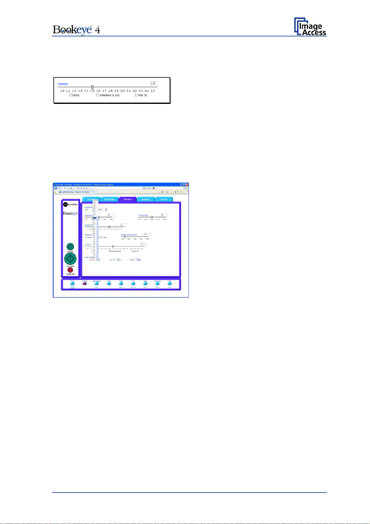
Gamma
The Gamma slider performs gamma correction directly inside the camera electronics.
Picture 59: Gamma slider
Three typical settings (sRGB, Windows & SGI and Mac OS) are available via the check
boxes directly below the slider.
Color Gain
The Color Gain drop down list changes the gain on a specific channel. This function is
used to eliminate any color shift or tints from the background.
Picture 60: Color gain drop down list
Operation Manual Page 57
Page 58
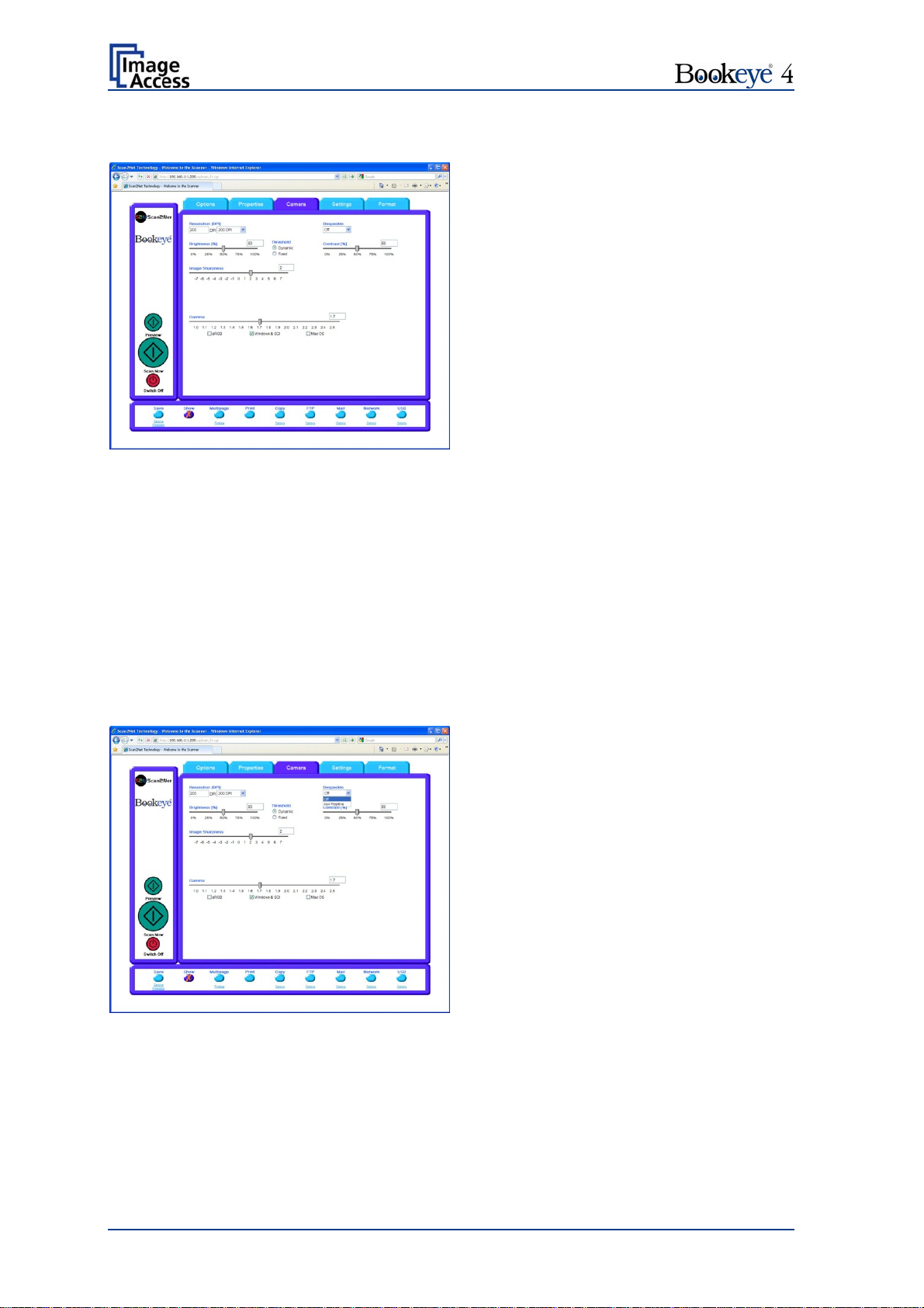
C.2.3.1 Threshold Dynamic / Threshold Fixed
Picture 61: Threshold method selector
If the color mode Binary is selected, an additional button allows to select between
Dynamic and Fixed threshold.
Dynamic The contrast level in the image varies depending on the content of the
document. This can help to improve fine details in the image.
Note: In this mode, set the value of the contrast slider carefully because
unexpected image artifacts can occur if it is set to the extreme values.
Fixed The contrast level is fixed to a specific value.
C.2.3.2 Despeckle
Picture 62: Despeckle function
The Despeckle function is only available in the color mode Binary.
This function removes isolated speckles in the image. Its use is recommended if old
documents on crumpled paper or vellum are scanned.
Page 58 Operation Manual
Page 59

C.2.4 The Settings Screen
Picture 63: Settings screen
Language Selector Sets the language of the user interface. Available languages are:
English (english)
German (deutsch)
French (francais)
Polish (polski)
Russian (Cyrillic script).
Chinese (Chinese symbols)
Note: After selecting the language the user interface changes
immediately to the selected language.
Note: If Russian or Chinese is selected, all text is displayed in
the corresponding script or symbols.
Operation Manual Page 59
Page 60
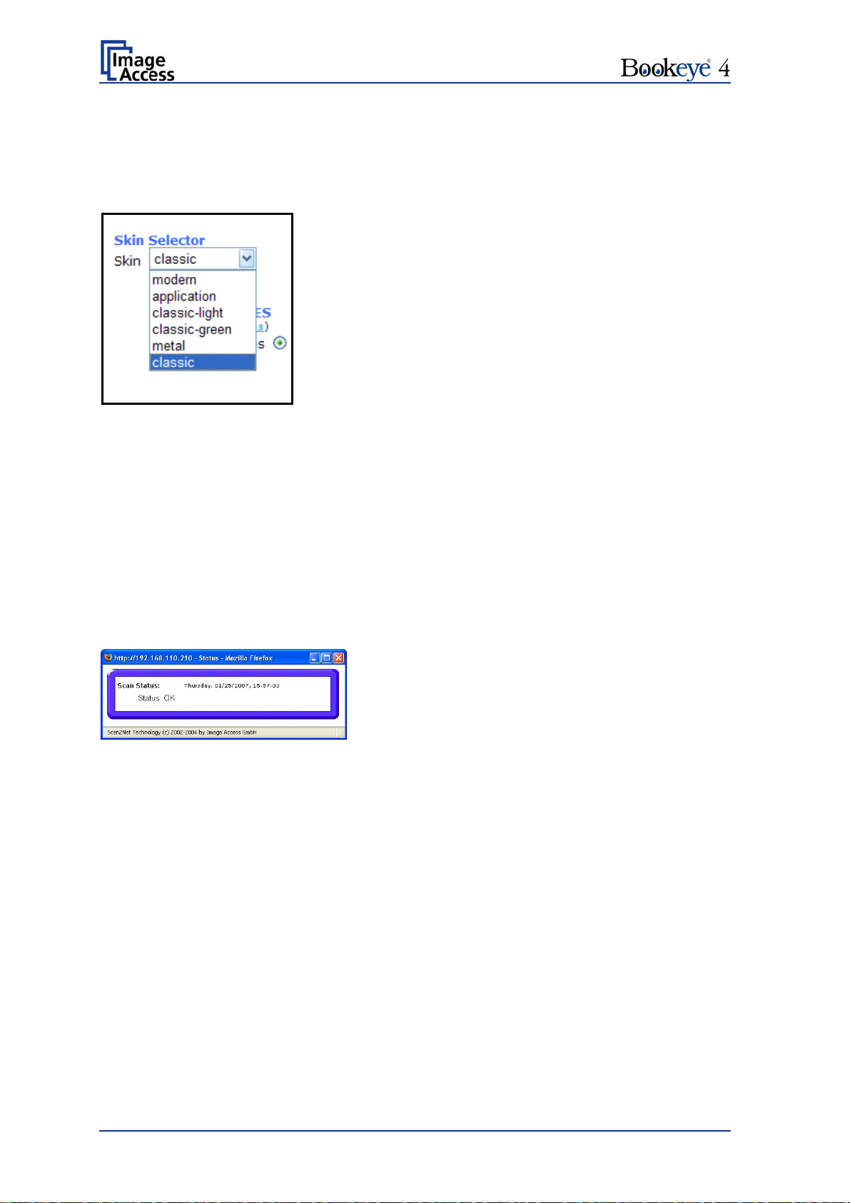
Skin Selector
This selector allows the operator to choose between different graphic presentations
(skins) for the user interface. The skins differ in colors, in the graphic elements used for
the buttons and in the controls.
The cutout on the left shows the currently available
skins. Additional skins can be designed and integrated
by the user.
Picture 64: Available skins
Tool Tips
If activated, the user will be informed with a brief text message about the available
functions in each screen. With the drop down list, the delay time can be defined.
No Tool Tips switches this function off.
Show Status Window
If set to Yes, a small window opens where scan status information is displayed.
Picture 65: Scan status window
Page 60 Operation Manual
Page 61
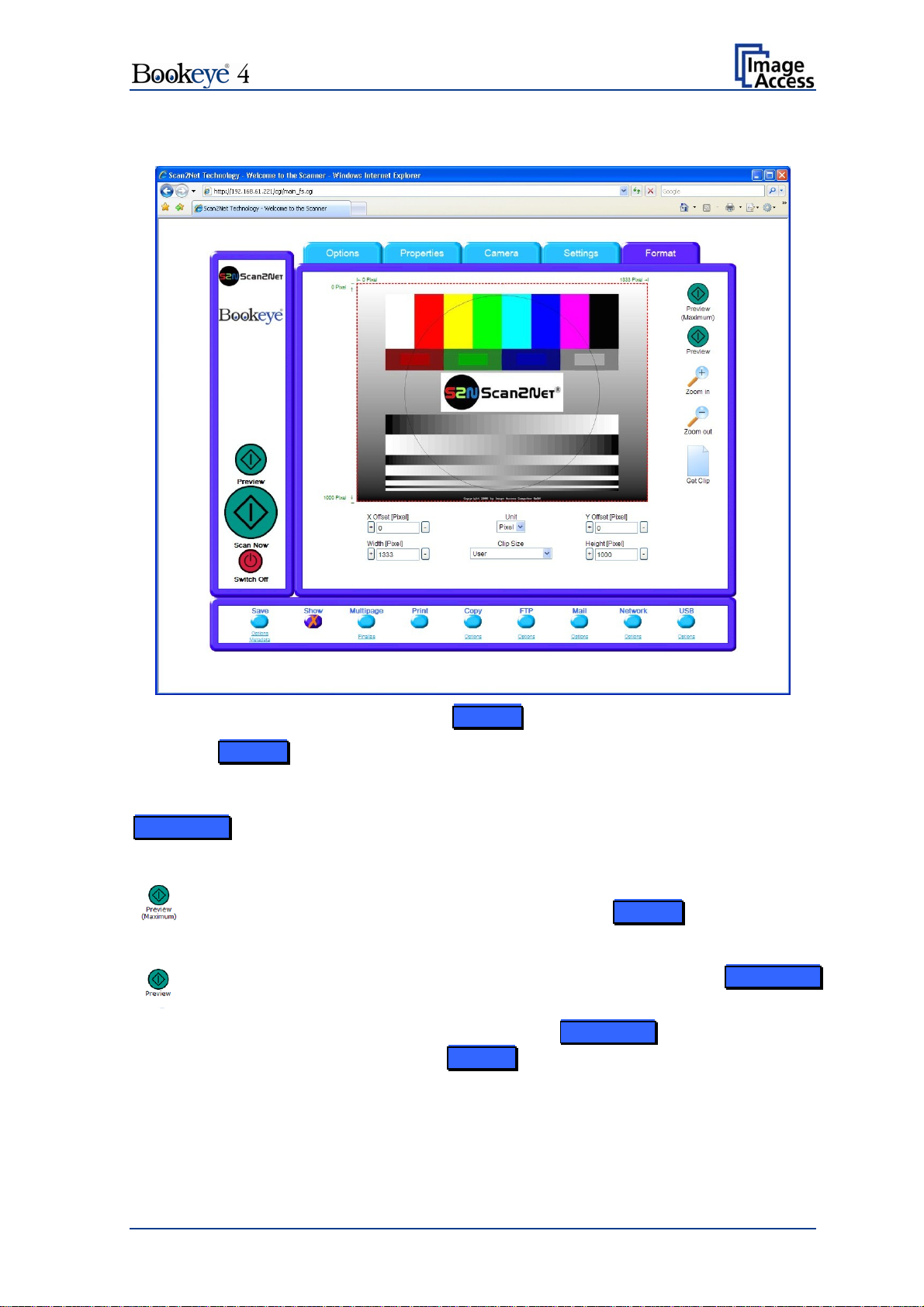
C.2.5 The Format Screen
Picture 66: Format screen
When the Format screen is selected, the test image shown in the above picture is
displayed.
The dimension of the image and the color mode depends on the settings made in the
Properties screen.
The Preview (Maximum) button allows to re
The image will be displayed in the preview area of the Format screen.
scans the complete document area.
The Preview button rescans the document area which is set in the Properties
screen.
For a new preview scan, first change to the Properties screen, set the new
format, and finally return to the Format screen. Click on the Preview button to
display the new image.
Operation Manual Page 61
Page 62
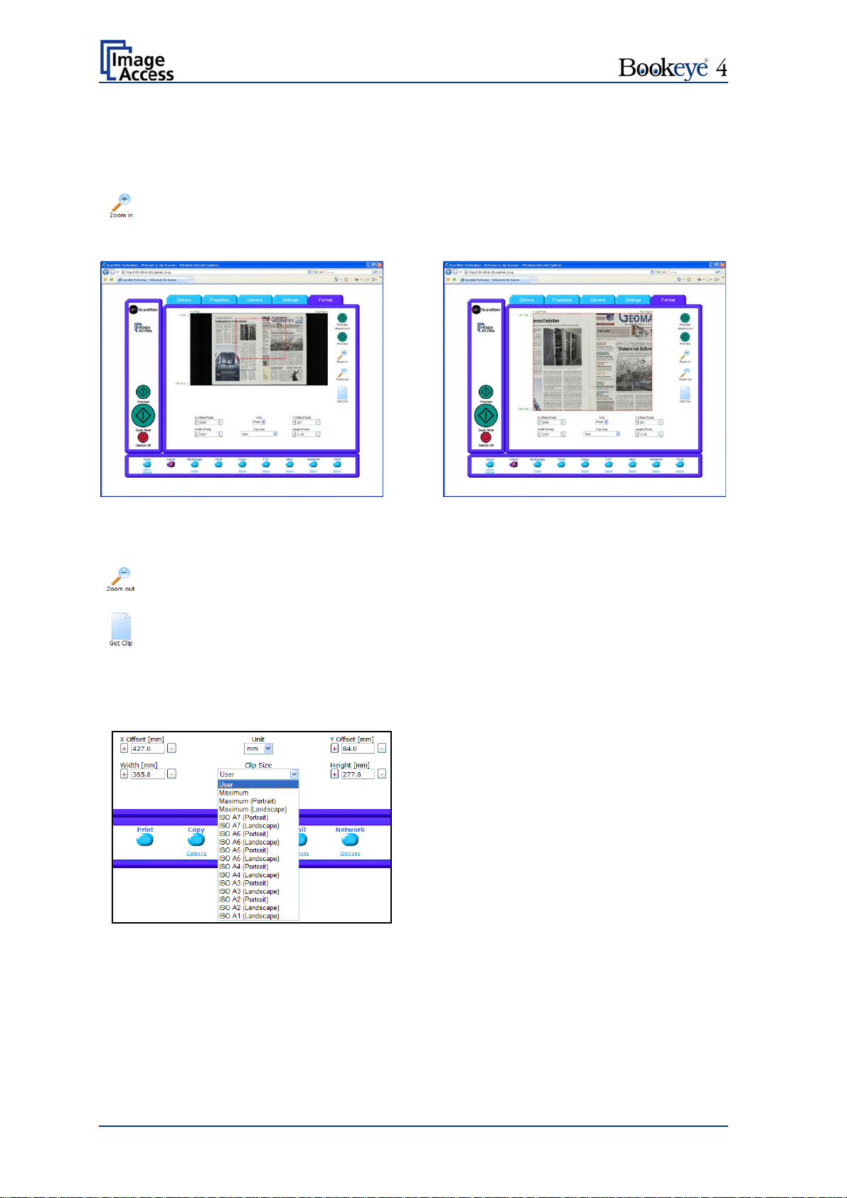
To select a specific area of the image, click with the mouse in the preview area and drag a
rectangle. Dragging with the mouse button clicked and pressed, the rectangle starts in the
upper left corner and ends in the lower right corner.
Click the Zoom in button to display the selected area of the image in detail.
Picture 67: Rectangle dragged with mouse
Click the Zoom out button to return to the previous dimension of the image.
Click the Get Clip button to get the selected area of the image in full resolution
in a separate window.
X Offset / Y Offset defines the position of
the rectangle.
Picture 69: List of available clip size formats
Picture 68: "Zoom in" result
Unit allows the user t
o select from a list
the unit of measurement for the
specification of the rectangle.
Width / Height allow the user to set the
dimension of the rectangle for the specific
area.
Clip Size offers a list of formats for the
specific area. The content of the list
depends on the size of the preview scan
area. That means, the smaller the preview
scan area, the shorter the list of available
formats.
Page 62 Operation Manual
Page 63
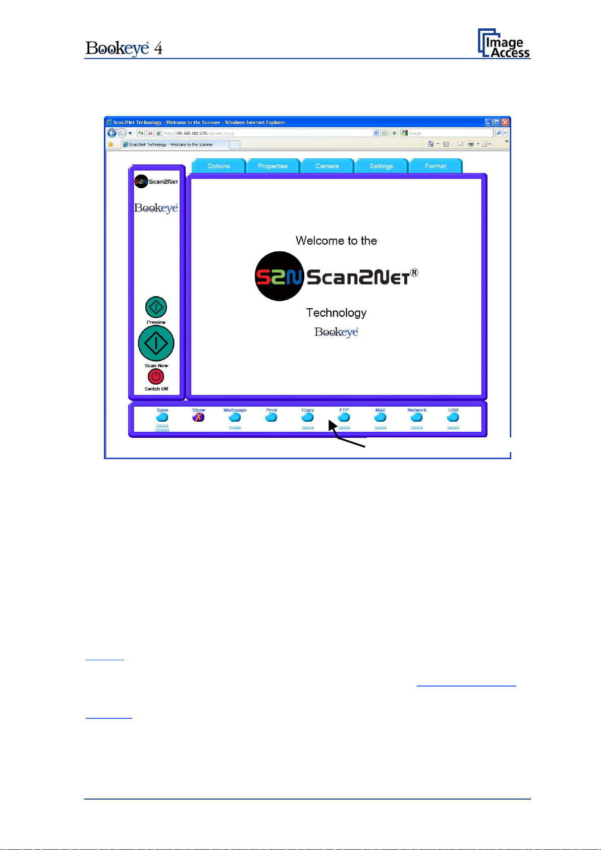
C.3 Output Options
Select output option here
Picture 70: Output options
Nine output options are available on a Bookeye 4 scanner. Each option is selectable at
the bottom part of the main window.
C.3.1 Output Option Save
Select the output mode by clicking with the mouse on the button Save.
When the output option Save is selected a preview window will not open.
This output option scans to a local or to a network disk drive. After the scan is performed,
a window opens and the default file name is shown. This window allows to select the
directory where the image should be stored and to change the file name.
Options
Metadata
Click on this link to define the file name. An additional window will open.
Enter the desired file name. When defining the file name, variables can be
used. To learn more about the variables click on Wildcard characters
the window Image Output: File Name.
Click on this link to change the metadata stored with the image. An
additional window will open. Enter the metadata here.
in
Operation Manual Page 63
Page 64

C.3.2 Output Option Show
In most cases, the button Show is activated.
Picture 71: Output Option Show
A scan will open a new browser window and the image is displayed the screen.
The output options described in this chapter are accessible via the above menu but are
also present in the upper part of each scanned image.
Picture 72: Output Options in Scan Window
Their functionality is identical, therefore only the output option screen is described here.
Page 64 Operation Manual
Page 65

C.3.3 Output Option Multipage
Picture 73: Output Option Multipage
Selecting the output option Multipage allows saving scanned images in one multipage
image.
Note: When the output option Multipage is selected, a preview window will not open.
Available output formats for the multipage image are TIFF or PDF. The format depends on
the selected file format which is defined in Properties File Format (see chapter
C.2.2)
Selected file format Multipage format
JPEG TIFF
PNM TIFF
TIFF, JPEG compression TIFF
TIFF, no compression TIFF
PDF, JPEG compression PDF
PDF, no compression PDF
Operation Manual Page 65
Page 66

While the scan sequence is running, a status window shows the current status. At the end
of the scan sequence Buffering Image is displayed.
To view the scanned images and to select the images for the multipage image, click on
the link Finalize.
A pop-up window opens and shows the
scanned images
since Multipage has been
selected.
If the pop-up window is already open, it can be
refreshed by clicking the Reload Window
button or by clicking at Finalize in the main
window.
The content of the pop-up window is not
refreshed a
utomatically.
By clicking the checkbox below each image,
the user can select or unselect the images for
the multipage image.
Picture 74: Pop-up window to select
images for multipage image
The buttons Finalize (xxx) transfer the
multipage image to the corresponding target.
Empty Buffers deletes all images in the
buffer.
Reload Window refreshes the content of the
pop-up window.
Close Window closes the pop-up window.
Page 66 Operation Manual
Page 67

C.3.4 Output Option Print
This output option prints the image at a locally configured printer.
Picture 75: Output Option Print
After the scan is executed, the standard printer interface opens. The user can select any
of the available printers.
Picture 76: Available List of Printers for Option Print
Operation Manual Page 67
Page 68

C.3.5 Output Option Copy
This output option prints directly to a previously installed network printer. The Option key
is used to configure the remotely connected printer.
Picture 77
: Output Option Copy
C.3.5.1 Remote Printer
Parameter Description
Printer Preset Choose a printer configuration out of five possible set of
you can change
Address
(with IP Networking only)
Port (9100)
(with IP Networking only)
Connection Timeout
(with IP Networking only)
Port (139)
(with SMB Printer Queue only)
(with SMB Printer Queue only)
parameters. If you click on Change Name
the name of this set.
Choose between IP Networking and SMB Printer Queue. Connection Type
Enter the IP address of the printer.
Enter the IP port of the remote printer. Default is port 9100.
Choose the timeout for connecting to the remote printer
before the connection is aborted.
Enter the IP port of the remote printer. Default is port 139.
Select Yes or No Server Authentication
Note: Each change of an entry field is transferred to the scanner immediately.
Page 68 Operation Manual
Page 69

Remote Printer, continued
Parameter Description
Login
(with SMB Printer Queue only)
Enter the login for the printer if Server Authentication is set
to Yes.
Password Enter the password for the printer if Server Authentication
is set to Yes.
SMB Path
(with SMB Printer Queue only)
Enter the path of the directory where the printer is
established.
Data Format Choose the data format of the remote printer. Selectable
data formats are Postscript, Postscript with framing HP/PJL
communication and HP DesignJet (HP/RTL) compliant
printers. Changing the data format will change some of the
options in this configuration window.
Data Compression
(with HP printers only)
Select the data compression of the data to be sent to the
printer.
Resolution Select the printing resolution. If an exact 1:1 copy of the
scanned document is required, the scanning resolution and
printing resolution must match.
Choose the paper format for the output. Paper Format
(not with HP Design Jet)
Duplex Print Switch on/off printing on both sides of a sheet (duplex).
Paper Feed Select the paper feed method for the remote printer. The
menu may contain manual paper feed, various paper trays
and paper rolls.
Copies Number of copies of each print
Operation Manual Page 69
Page 70

C.3.5.2 Printing Enhancement
Parameter Description
Quality Level
(with DesignJet only)
ICC Profile
(not with all printer types)
Toggle the printing quality from draft to high quality.
Only available with HP/RTL compliant remote printers.
Select the profile used for printing. Administrators can
upload a set of printer ICC profiles in the Poweruser setup.
Only available with HP/RTL compliant remote printers.
Color Matching
(not with all printer types)
Select the color rendering method for the remote printer.
Best Fit: The printer uses the nearest matching colors of
its own color space.
Printer Color Range: The printer uses the full range of its
color space despite of the color definition of the scanned
document.
Only available in conjunction with HP/PJL communication
framework.
Edge Antialiasing
(not with all printer types)
Switch on/off printer featured edge anti-aliasing.
Only available in conjunction with HP/PJL communication
framework.
Brightness Modify the brightness level of the print.
Only available with HP/RTL compliant remote printers.
Contrast Modify the contrast level of the print.
Only available with HP/RTL compliant remote printers.
Gamma Modify the printer gamma.
Only available with HP/RTL compliant remote printers.
Note: Each change to an entry field is transferred to the scanner immediately.
Page 70 Operation Manual
Page 71

C.3.6 Output Option FTP Upload
The scanner scans directly to an FTP server.
Picture 78: Output Option FTP Upload
Go to Options to configure the FTP interface. A configuration window will pop up.
C.3.6.1 FTP Server
Parameter Description
Preset Choose a preconfigured set of parameters out of five possible
sets of parameters. If you click on Change Name
change the name of this set.
Address Enter the IP address of the remote FTP server.
Port (21) Enter the IP port of the remote FTP server.
Default is port 21.
Server Authentication Select the authentication method.
Login Enter the login name.
Password Enter the password for the login at the remote FTP server. The
password is stored using encryption.
Upload Path Enter the upload path on the remote FTP server, starting with /
(root). Click on the icon, to browse the directory structure of the
remote FTP server. Note: You must have a valid login for
browsing the directory structure.
you can
Operation Manual Page 71
Page 72

FTP Server, continued
Parameter Description
File name Enter the file name prefix. A time stamp will be added to this
prefix to form the complete file name.
Use a FTP Proxy? Switch on/off the use of an FTP proxy for connecting to a remote
FTP server outside the local network.
FTP Proxy Address Specify the IP address of the FTP proxy.
Port Specify the IP port of the FTP proxy.
Configuration Test:
Click on this link to test the settings. A separate window will open
and shows the test results.
Note: Each change to an entry field is transferred to the scanner immediately.
Page 72 Operation Manual
Page 73
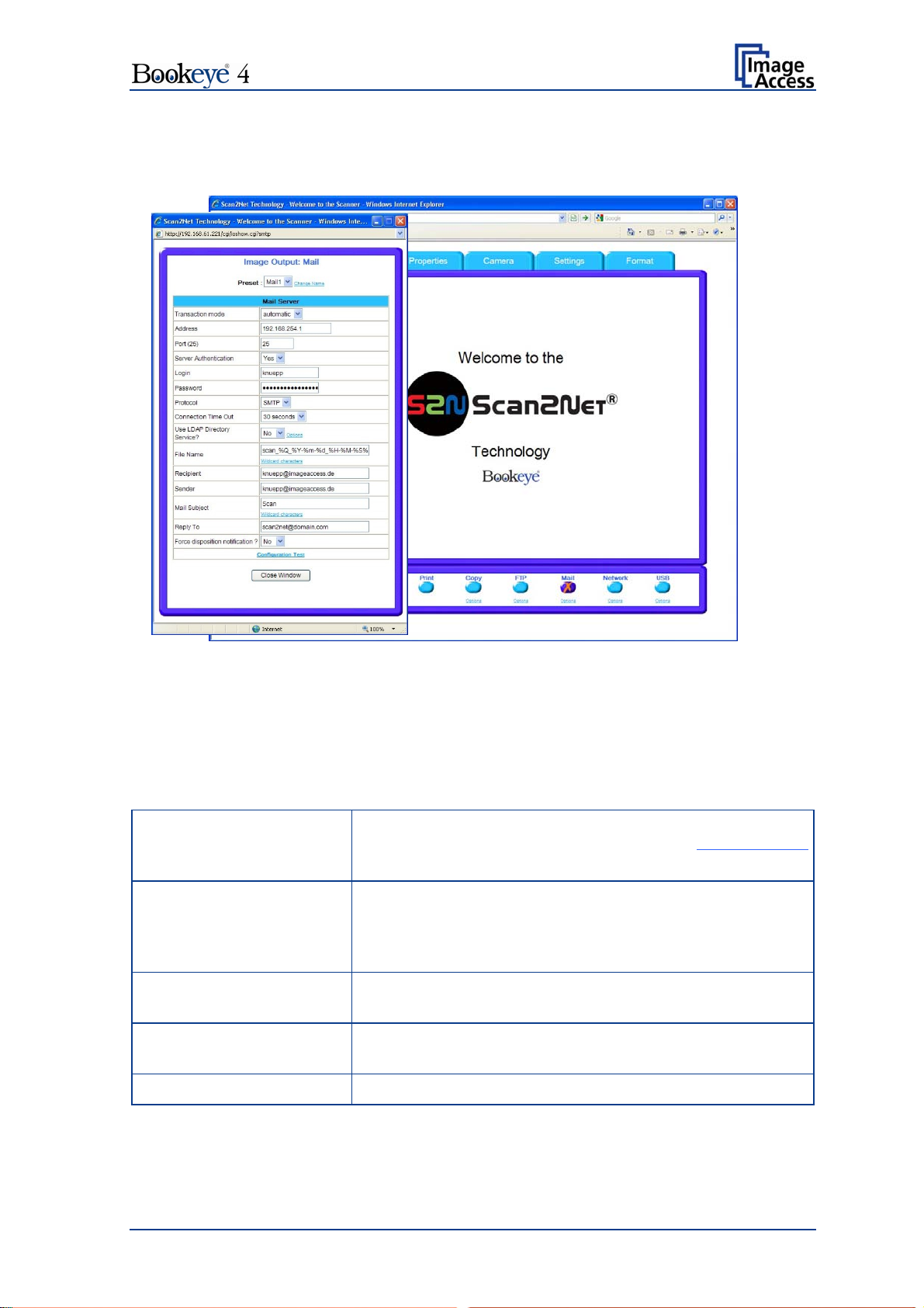
C.3.7 Output Option Mail
The scanner can send each scan directly via e-mail.
Picture 79: Output Option Mail
Go to Options to configure the mail interface. The above configuration window will pop
up.
C.3.7.1 Mail Server
Parameter Description
Preset Choose a preconfigured set of parameters out of five
possible sets of parameters. If you click on Change Name
you can change the name of this set.
Transaction mode Decide if all scanned documents will be sent to the same
recipient (automatic batch mode) or if the scanner should
ask after every scan (interactive). Select the appropriate
transaction mode.
Address Enter the IP address of the outgoing mail (SMTP/LMTP)
server.
Port (25) Enter the IP Port of the outgoing mail server.
Default: Port 25.
Server Authentication Set to YES if the mail server requires an authentication.
Operation Manual Page 73
Page 74

Mail Server, continued
Paramater Description
Login Enter the user name for authentication at the outgoing mail
server.
Password Enter the password for authentication at the outgoing mail
server. The password is stored using encryption.
Protocol Choose the connection protocol. SMTP is the most
common protocol.
Connection Time Out Choose the timeout for connecting to the outgoing mail
server before the connection is aborted.
Use LDAP Directory
Service?
LDAP directory service can be used to send the mails. To
configure the parameters click on the link Options
.
File Name Enter the file name. Variables can be used to complete the
file name. To learn more about the variables, click on the
link Wildcard characters
.
Recipient Type in the recipient of the e-mail.
Format: fully qualified e-mail address.
Sender Type in the sender of the e-mail.
Format: fully qualified e-mail address.
Mail Subject Type in the e-mail subject. (Optional)
Variables can be added to the mail subject. To learn more
about the variables, click on the link Wildcard characters
.
Reply To Type in a reply address for answers. (Optional)
Format: fully qualified e-mail address.
Force disposition
notification?
Request a notification when the recipient has opened the
mail.
Note: This feature is not supported by all mail servers or
clients.
Configuration Test
: Click on this link to test the settings. A separate window will open
and shows the test results.
Note: Each change to an entry field is transferred to the scanner immediately.
Page 74 Operation Manual
Page 75

C.3.8 Output Option Network
SMB is a network protocol which is used by Microsoft Windows-based networks.
If the output option Network is selected, the scans will be stored directly in a network
directory.
Picture 80: Output Option Network
Go to Option to configure the SMB Upload interface. A configuration window will pop up.
Operation Manual Page 75
Page 76

C.3.8.1 SMB Configuration
Parameter Description
Preset Choose a pre configured set of parameters out of five
possible sets of parameters. If you click on Change Name
you can change the name of this set.
Port (139) Enter the IP port for the SMB network communication.
Default is port 139.
Server Authentication Select the authentication method.
Login Enter the user name on the Windows workstation/file server
which you want to connect to.
Password Enter the password associated with the user name for the
login at the Windows workstation/file server which you want
to connect to. The password is stored using encryption.
SMB Path Enter the upload path on the Windows workstation. Start with
a backslash (/) for the root directory. Click the icon to browse
the workstation/server list and the directory structure of the
Windows workstation/file server.
Note: You must have a valid login for browsing the directory
structure.
File Name Enter the file name. A time stamp will be added to this prefix
to form the complete file name.
Configuration Test
: Click on this link to test the settings. A separate window will open
and shows the test results.
Note: Each change to an entry field is transferred to the scanner immediately.
Page 76 Operation Manual
Page 77
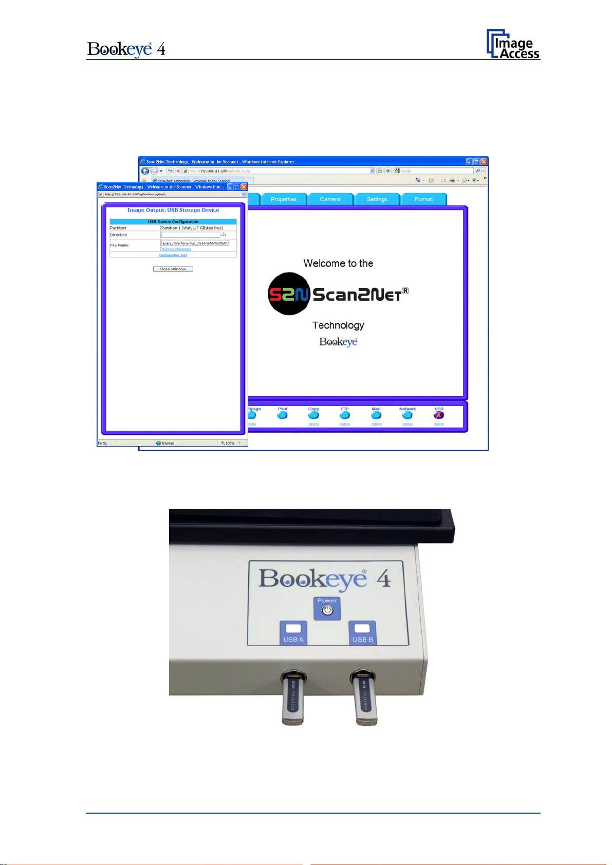
C.3.9 Output Option USB
Universal Serial Bus (USB) is a serial bus standard for interface devices, e.g. storage
devices. The output option USB enables direct scanning to a USB Standard-A flash
memory data storage device.
Picture 81: Output Option USB
On the front of the Bookeye 4 scanner, two USB connectors can be found, where suitable
storage media can be inserted.
Picture 82: USB sticks inserted at front of Bookeye 4
Operation Manual Page 77
Page 78

C.3.9.1 USB Storage Device
Go to Options to configure the USB interface. A configuration window will pop up.
Parameter Description
Partition Shows the status and available memory of the actual
mounted partition on the connected USB flash device.
Directory Allows the user to choose a subdirectory on the connected
USB drive for storing the scans.
File name Shows the current setting of wildcard characters for the
automated naming scheme of each produced image file.
Wildcard characters Offer the complete list of the available wild cards.
Configuration Test
: Click on this link to test the settings. A separate window will open
and shows the test results.
Note: Each change to an entry field is transferred to the scanner immediately.
Page 78 Operation Manual
Page 79
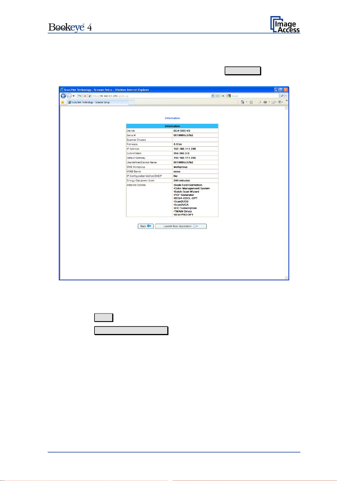
C.4 Information
The start screen (Picture 46) shows three buttons. The button Information gives a short
summary of the device parameters.
Picture 83: Information
The screen is helpful if technical support is necessary. It shows e.g. the exact device type,
the installed firmware version as well as currently installed options.
Click the button Back to return to the start screen.
Click the button Launch Scan Application to switch to the main screen (Picture 47).
Operation Manual Page 79
Page 80

D Technical Data
D.1 Scanner Specifications
Scan Area
Maximum Scan Area [mm] 620 x 460 mm
Resolution 150 – 600 dpi
Luminosity
Scanning Max. 1800 LUX
Stand-by, idle 0 LUX (lamps off)
Lamps:
High Power White LED IR and UV radiation free
Lifetime 50000 hours operating time
D.2 Ambient Conditions
Operating Temperature +5 to +40° Celsius
Storage Temperature 0 to +60° Celsius
Relative Humidity 20 to 80% (non-condensing)
Ambient luminance ≥ 300 Lux
Noise Level < 50 dB(A) (Operating)
< 30 dB(A) (Stand-by)
Page 80 Operation Manual
Page 81

D.3 Electrical Specifications
External Power Supply
Voltage 90 – 264 V AC
Frequency 47 – 63 Hz
Inrush current 120 A max / 264 V AC
Efficiency 85 %
Idle consumption ≤ 0.5 W
Operating temperature 0 … +65 °C
Operating humidity 10 …93 % RH, non-condensing
ECO standard CEC level IV
Scanner
Voltage 24 V DC
Current Max. 5 A
Power Consumption
Standby 4,5
Ready to scan, monitor on 75,0 W
Scan @ 400 dpi, format “Max”, monitor on 135,0 W
White Balance calibration, monitor on 180,0 W
Power off, monitor on 0,5 W
W
Operation Manual Page 81
Page 82

D.4 Dimensions and Weight
Scanner outer dimensions , book cradle closed 825 x 670 x 640 mm (H x W x D)
32.5 x 26.4 x 25.2 inch
Scanner outer dimensions , book cradle opened 825 x 740 x 640 mm (H x W x D)
32.5 x 29.2 x 25.2 inch
Total weight of scanner, ready to use Approx. 34 kg / 75 lbs
Dimensions Transport Box
Weight Transport Box: 40 kg / 88 lbs
Total shipping weight 74 kg / 162.8 lbs
1005 x 805 x 815 mm (H x W x D)
39.6 x 31.7 x 32.1 inch
Page 82 Operation Manual
 Loading...